KR100627706B1 - Data processing apparatus, image processing apparatus, camera, and data processing method - Google Patents
Data processing apparatus, image processing apparatus, camera, and data processing methodDownload PDFInfo
- Publication number
- KR100627706B1 KR100627706B1KR1020040045714AKR20040045714AKR100627706B1KR 100627706 B1KR100627706 B1KR 100627706B1KR 1020040045714 AKR1020040045714 AKR 1020040045714AKR 20040045714 AKR20040045714 AKR 20040045714AKR 100627706 B1KR100627706 B1KR 100627706B1
- Authority
- KR
- South Korea
- Prior art keywords
- interpolation
- pattern
- pixel
- pixels
- interpolated
- Prior art date
- Legal status (The legal status is an assumption and is not a legal conclusion. Google has not performed a legal analysis and makes no representation as to the accuracy of the status listed.)
- Expired - Fee Related
Links
Images


Classifications
- G—PHYSICS
- G06—COMPUTING OR CALCULATING; COUNTING
- G06T—IMAGE DATA PROCESSING OR GENERATION, IN GENERAL
- G06T3/00—Geometric image transformations in the plane of the image
- G06T3/40—Scaling of whole images or parts thereof, e.g. expanding or contracting
- G06T3/4007—Scaling of whole images or parts thereof, e.g. expanding or contracting based on interpolation, e.g. bilinear interpolation
- H—ELECTRICITY
- H04—ELECTRIC COMMUNICATION TECHNIQUE
- H04N—PICTORIAL COMMUNICATION, e.g. TELEVISION
- H04N23/00—Cameras or camera modules comprising electronic image sensors; Control thereof
- H04N23/10—Cameras or camera modules comprising electronic image sensors; Control thereof for generating image signals from different wavelengths
- G—PHYSICS
- G06—COMPUTING OR CALCULATING; COUNTING
- G06T—IMAGE DATA PROCESSING OR GENERATION, IN GENERAL
- G06T3/00—Geometric image transformations in the plane of the image
- G06T3/40—Scaling of whole images or parts thereof, e.g. expanding or contracting
- G06T3/4015—Image demosaicing, e.g. colour filter arrays [CFA] or Bayer patterns
- H—ELECTRICITY
- H04—ELECTRIC COMMUNICATION TECHNIQUE
- H04N—PICTORIAL COMMUNICATION, e.g. TELEVISION
- H04N23/00—Cameras or camera modules comprising electronic image sensors; Control thereof
- H04N23/80—Camera processing pipelines; Components thereof
- H04N23/84—Camera processing pipelines; Components thereof for processing colour signals
- H04N23/843—Demosaicing, e.g. interpolating colour pixel values
- H—ELECTRICITY
- H04—ELECTRIC COMMUNICATION TECHNIQUE
- H04N—PICTORIAL COMMUNICATION, e.g. TELEVISION
- H04N25/00—Circuitry of solid-state image sensors [SSIS]; Control thereof
- H04N25/10—Circuitry of solid-state image sensors [SSIS]; Control thereof for transforming different wavelengths into image signals
- H04N25/11—Arrangement of colour filter arrays [CFA]; Filter mosaics
- H04N25/13—Arrangement of colour filter arrays [CFA]; Filter mosaics characterised by the spectral characteristics of the filter elements
- H04N25/134—Arrangement of colour filter arrays [CFA]; Filter mosaics characterised by the spectral characteristics of the filter elements based on three different wavelength filter elements
Landscapes
- Engineering & Computer Science (AREA)
- Physics & Mathematics (AREA)
- Multimedia (AREA)
- Signal Processing (AREA)
- General Physics & Mathematics (AREA)
- Theoretical Computer Science (AREA)
- Spectroscopy & Molecular Physics (AREA)
- Color Television Image Signal Generators (AREA)
- Image Processing (AREA)
Abstract
Translated fromKoreanDescription
Translated fromKorean도 1은 본 발명의 실시예에 따른 카메라의 구성을 나타내는 블록도이다.1 is a block diagram showing the configuration of a camera according to an embodiment of the present invention.
도 2는 도 1의 보간부에 의해 행해지는 보간 절차를 설명하는 플로우챠트이다.FIG. 2 is a flowchart for explaining an interpolation procedure performed by the interpolation section of FIG. 1.
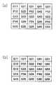
도 3(a) 및 (b)는 도 1의 라인 메모리에 기억된 화상신호를 나타내는 화상도이며, 여기서 P와 Q는 각각 R 화소 또는 B 화소, 또는 B 화소 또는 R 화소를 가리킨다.3A and 3B are image diagrams showing image signals stored in the line memory of Fig. 1, wherein P and Q indicate R pixels or B pixels, or B pixels or R pixels, respectively.
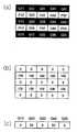
도 4(a) 내지 (h)는 G 화소에 관한 예시적인 보간 패턴을 나타내는 도면이며, 여기서 P와 Q는 각각 R 화소 또는 B 화소, 또는 B 화소 또는 R 화소를 가리킨다.4 (a) to (h) are diagrams showing exemplary interpolation patterns for G pixels, where P and Q indicate R pixels or B pixels, or B pixels or R pixels, respectively.
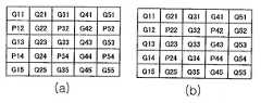
도 5(a) 내지 (d)는 본 발명에 따른 보간에 대해 보간 패턴을 판정하는 방법을 설명하는 도면이며, 여기서 P와 Q는 각각 R 화소 또는 B 화소, 또는 B 화소 또는 R 화소를 가리킨다.5A to 5D are diagrams for explaining a method of determining an interpolation pattern for interpolation according to the present invention, wherein P and Q indicate R pixels or B pixels, or B pixels or R pixels, respectively.
도 6(a) 내지 (h)는 P 화소에 관한 예시적인 보간 패턴을 나타내는 도면이며, 여기서 P와 Q는 각각 R 화소 또는 B 화소, 또는 B 화소 또는 R 화소를 가리킨다.6 (a) to (h) are diagrams showing exemplary interpolation patterns for P pixels, where P and Q indicate R pixels or B pixels, or B pixels or R pixels, respectively.
도 7(a) 내지 (h)는 본 발명에 따른 화상처리로서 에지강조처리를 설명하는 도면이며, 여기서 P와 Q는 각각 R 화소 또는 B 화소, 또는 B 화소 또는 R 화소를 가리킨다.7A to 7H are diagrams for explaining edge emphasis processing as image processing according to the present invention, wherein P and Q indicate R pixels or B pixels, or B pixels or R pixels, respectively.
도 8은 컬러필터에 있어서 색에 대한 종래의 바이어 어레이 배열을 나타내는 도면이다.8 is a diagram illustrating a conventional via array arrangement for colors in a color filter.
도 9(a) 및 (b)는 종래의 보간 기술을 설명하는 도면이며, 여기서 P와 Q는 각각 R 화소 또는 B 화소, 또는 B 화소 또는 R 화소를 가리킨다.9 (a) and 9 (b) are diagrams illustrating a conventional interpolation technique, where P and Q indicate R pixels or B pixels, or B pixels or R pixels, respectively.
도 10(a) 내지 (e)는 종래의 보간 기술의 문제점을 설명하는 도면이며, 여기서 P와 Q는 각각 R 화소 또는 B 화소, 또는 B 화소 또는 R 화소를 가리킨다.10 (a) to 10 (e) illustrate the problems of the conventional interpolation technique, where P and Q indicate R pixels or B pixels, or B pixels or R pixels, respectively.
도 11(a) 내지 (c)는 종래의 보간 기술의 다른 문제점을 설명하는 도면이며, 여기서 P와 Q는 각각 R 화소 또는 B 화소, 또는 B 화소 또는 R 화소를 가리킨다.11 (a) to 11 (c) illustrate another problem of the conventional interpolation technique, where P and Q indicate R pixels or B pixels, or B pixels or R pixels, respectively.
(도면의 주요 부분에 대한 부호의 설명)(Explanation of symbols for the main parts of the drawing)
1: 고체촬상소자1: solid state imaging device
2: CDS2: CDS
3: AGC3: AGC
4: A/D 변환회로4: A / D conversion circuit
5: DSP5: DSP
6: TG6: TG
7: 라인 메모리7: line memory
8: 보간부8: interpolator
9: 보간 패턴 기억 메모리9: Interpolation pattern memory
10: 화상신호처리부10: image signal processing unit
11: I/F부11: I / F part
12: 데이터처리장치12: data processing device
100: 카메라100: camera
본 발명은 누락된 색신호를 각 화소의 화상신호로 보간하는 데이터처리장치(예컨대, 카메라 신호처리장치 등)에 관한 것으로, 고체촬상소자를 갖는 카메라(예컨대, 비디오 카메라, 디지털 카메라 등)에 사용된다. 또한, 이 데이터처리장치를 사용하는 데이터처리방법, 상기 데이터처리방법을 사용하는 화상처리장치, 및 이 화상처리장치와 고체촬상소자를 사용하는 카메라(예컨대, 비디오 카메라, 디지털 카메라, 카메라를 갖는 이동전화 등)에 관한 것이다.BACKGROUND OF THE
종래의 카메라(예컨대, 비디오 카메라, 디지털 카메라 등, 그리고 이하, 카메라로 칭함)에 있어서, 하나의 고체촬상소자가 사용되고, 컬러필터는 상기 고체촬상소자의 화소 상에 이산적으로 배치된다.In a conventional camera (e.g., a video camera, a digital camera, etc., and hereinafter referred to as a camera), one solid state image pickup device is used, and the color filter is disposed discretely on the pixels of the solid state image pickup device.
각 컬러필터는 3색(3원색), 예컨대, 레드(R), 그린(G) 및 블루(B) 중 하나를 갖는다. R, G 및 B 필터 중 하나는 각 화소 상에 배치된다. 화소에 제공된 컬러필터의 색 이외의 색(색신호)은 연산에 의해 얻어질 수 있다. 이 경우에 있어서, 공 간적으로 연속적인 데이터(여기서, 2차원)는 마치 3개의 컬러필터가 연속적으로 제공된 것과 같이 얻어질 수 있다. 공간적으로 연속적인 데이터를 얻기 위한 이러한 연산은 보간이라 칭하여진다.Each color filter has one of three colors (three primary colors), for example, red (R), green (G), and blue (B). One of the R, G, and B filters is disposed on each pixel. Colors (color signals) other than the colors of the color filters provided to the pixels can be obtained by calculation. In this case, spatially continuous data (here two-dimensional) can be obtained as if three color filters were continuously provided. This operation to obtain spatially continuous data is called interpolation.
이하, 보간이 상세하게 설명된다.Interpolation is described in detail below.
도 8은 종래의 컬러필터에 있어서의 색 배열을 나타내는 도면이다.8 is a diagram illustrating a color arrangement in a conventional color filter.
일반적으로, 컬러필터 플레이트에 있어서, G 컬러필터는 체크보드(checkboard) 패턴으로 배열되지만, R 및 B 컬러필터 양자는 R 또는 B 컬러필터가 다른 라인 상에 배열되는 체크보드 패턴(checkerboard pattern)으로 또한 배열된다. 이 배열은 바이어 어레이(Bayer array)라 칭하여진다.Generally, in a color filter plate, the G color filters are arranged in a checkboard pattern, while both the R and B color filters are arranged in a checkerboard pattern in which the R or B color filters are arranged on different lines. Also arranged. This array is called a Bayer array.
고체촬상소자가 바이어 어레이를 갖는 컬러필터 플레이트를 통해 화상신호를 디지털화한다면, 각 화소는 하나의 색만을 표시하는 화상신호를 제공한다. 따라서, 화소에 제공되지 않는 색 데이터는, 각 화소에 대한 완전 컬러 화상신호(R, G 및 B 컬러 모두를 포함함)를 얻기 위해 누락된 색을 갖는 다른 화소의 화상신호에 기초하여 보간될 필요가 있다.If the solid state image pickup device digitizes an image signal through a color filter plate having a via array, each pixel provides an image signal displaying only one color. Thus, color data not provided to a pixel needs to be interpolated based on the image signal of another pixel having a missing color in order to obtain a full color image signal (including both R, G and B colors) for each pixel. There is.
이 경우에 있어서, G 화소와, R 및 B 화소는 개별 방법에 의해 보간될다.In this case, the G pixels and the R and B pixels are interpolated by separate methods.
도 9(a) 및 (b)는 종래의 보간 기술을 설명하는 도면이다. 이들 도면에 있어서, G 필터가 제공된 화소는 G로 표시된다. R 및 B 필터가 보간될 화소 상에 배열되기 때문에, R 및 B 필터가 제공된 화소는 각각 P 및 Q로 표시된다.9 (a) and 9 (b) are diagrams illustrating a conventional interpolation technique. In these figures, pixels provided with the G filter are denoted by G. Since the R and B filters are arranged on the pixels to be interpolated, the pixels provided with the R and B filters are denoted by P and Q, respectively.
도 9(a)에 도시된 바와 같이, 예컨대, G33은 보간될 화소로 간주된다. 화소의 R 및 B(P 및 Q) 데이터는 보간에 의해 구해질 필요가 있다. G 화소에 근접하는 것은 R 화소와 B 화소이다.As shown in Fig. 9A, for example, G33 is regarded as a pixel to be interpolated. R and B (P and Q) data of the pixel need to be obtained by interpolation. Proximity to the G pixel is the R pixel and the B pixel.
G33의 보간에 의해 구해진 P 및 Q는 P33 및 Q33으로 표시된다. 특히, P33 및 Q33은 하기의 공식에 의해 G33에 근접하는 P 데이터와 Q 데이터를 기초로 하여 계산된다:P and Q obtained by interpolation of G33 are represented by P33 and Q33. In particular, P33 and Q33 are calculated based on P data and Q data proximate to G33 by the following formula:
G33=G33G33 = G33
P33=(P32+P34)/2P33 = (P32 + P34) / 2
Q33=(Q23+Q43)/2.Q33 = (Q23 + Q43) / 2.
다음, 도 9(b)에 도시된 바와 같이, Q33은 보간될 화소로 간주된다. 화소의 G 및 P 데이터는 보간에 의해 구해진다. Q 화소에 근접하는 것은 G 화소와 P 화소이다.Next, as shown in Fig. 9B, Q33 is regarded as a pixel to be interpolated. G and P data of the pixel are obtained by interpolation. Proximities to the Q pixels are G pixels and P pixels.
Q33의 보간에 의해 구해진 G 및 P는 G33 및 P33으로 표시된다. 특히, G33 및 P33은 각각 하기의 공식에 의해 Q33에 근접하는 G 데이터와 P 데이터를 기초로 하여 계산된다:G and P obtained by interpolation of Q33 are represented by G33 and P33. In particular, G33 and P33 are respectively calculated based on the G data and P data proximate to Q33 by the following formula:
G33=(G23+G32+G34+G43)/4G33 = (G23 + G32 + G34 + G43) / 4
P33=(P22+P24+P42+P44)/4P33 = (P22 + P24 + P42 + P44) / 4
Q33=Q33Q33 = Q33
그러나, 상기 언급된 일반적인 보간 기술은, 아래에서 설명되는 바와 같이, 화상 왜곡과 에지부에서의 해상도 저하를 야기한다.However, the general interpolation technique mentioned above causes image distortion and resolution degradation at the edge portions, as described below.
이하, 이 문제점은 도 10(a)를 참조하여 설명되고, 여기서 수직 줄무늬 패턴이 촬상된다.This problem is hereinafter described with reference to Fig. 10A, where a vertical stripe pattern is imaged.
도 10(a)에 있어서, G11에서 G15로 형성된 라인은 전형적으로 화이트로 디스플레이되는 고해상도 라인이다. Q21에서 Q25로 형성된 라인은 전형적으로 블랙으로 디스플레이되는 저해상도 라인이다.In Figure 10 (a), the lines formed from G11 to G15 are high resolution lines that are typically displayed in white. Lines formed from Q21 to Q25 are typically low resolution lines displayed in black.
도 10(b)는 도 10(a)의 수직 줄무늬 패턴에서의 각 화소의 화상신호값을 나타내는 도면이며, 여기서 각 화이트 화소는 100값을 갖지만, 각 블랙 화소는 0값을 갖는다.Fig. 10 (b) shows the image signal value of each pixel in the vertical stripe pattern of Fig. 10 (a), where each white pixel has a value of 100, but each black pixel has a value of zero.
현재 G33은 보간될 화소로 간주된다. 보간은 상기에 언급된 공식에 따라 행해진다. 결과로서,Currently G33 is regarded as the pixel to be interpolated. Interpolation is done according to the formula mentioned above. As a result,
G33=100,G33 = 100,
P33=(P32+P34)/2=100, 및P33 = (P32 + P34) / 2 = 100, and
Q33=(Q23+Q43)/2=0.Q33 = (Q23 + Q43) / 2 = 0.
마찬가지로, 다른 모든 화소도 상기에 언급된 공식에 따라 보간될다. 그 결과는 도 10(c) 내지 도 10(e)에 표시된다. 도 10(c)는 보간 후 G의 값을 나타낸다. 도 10(d)는 보간 후 P의 값을 나타낸다. 도 10(e)는 보간 후 Q의 값을 나타낸다.Likewise, all other pixels can be interpolated according to the above mentioned formula. The result is shown in Figs. 10 (c) to 10 (e). 10 (c) shows the value of G after interpolation. 10 (d) shows the value of P after interpolation. 10 (e) shows the value of Q after interpolation.
도 10(c)에 도시된 바와 같이, G의 보간될 데이터는 수직 줄무늬 패턴을 나타내지 않기 때문에, 화상은 왜곡된다. 도 10(e)에 도시된 바와 같이, Q의 보간될 데이터는 수직 줄무늬 패턴을 나타내지 않으며, 여기서 줄무늬는 사라진다. 즉, 화상은 왜곡된다.As shown in Fig. 10 (c), since the data to be interpolated of G do not exhibit a vertical stripe pattern, the image is distorted. As shown in Fig. 10E, the data to be interpolated of Q does not exhibit a vertical stripe pattern, where the stripe disappears. In other words, the image is distorted.
예컨대, 일본국 특허공개 평7-59098호 공보에서는 보간에 의해 야기된 이러한 화상의 왜곡 문제점을 해결하고자 하는 시도가 진행되었다. 이 특허문헌에 있어 서, 화소의 그레이 레벨은 수평 또는 수직으로 근접하는 화소 사이의 차분(difference)을 기초로 하여 구해진다. 그레이 레벨은 기설정된 문턱치와 비교된다. 비교 결과에 기초하여, 보간은 행해진다.For example, Japanese Patent Laid-Open No. 7-59098 has attempted to solve such a distortion problem of an image caused by interpolation. In this patent document, the gray level of a pixel is obtained based on the difference between pixels that are horizontally or vertically adjacent. The gray level is compared with a preset threshold. Based on the comparison result, interpolation is performed.
이하, 상기 언급된 특허문헌에 개시된 보간 기술은 도 11(a)를 참조하여 설명되며, 여기서 수평 줄무늬 패턴이 촬상된다.Hereinafter, the interpolation technique disclosed in the above-mentioned patent document is described with reference to Fig. 11 (a), where a horizontal stripe pattern is imaged.
도 11(a)에 있어서, G11 내지 G51, G13 내지 G53, 및 G15 내지 G55로 각각 형성된 라인은 각각 저해상도를 가지며, 전형적으로 블랙으로 디스플레이된다. P12 내지 P52 및 P14 내지 P54로 각각 형성된 라인은 각각 고해상도를 가지며, 전형적으로 화이트로 디스플레이된다.In Fig. 11 (a), lines each formed of G11 to G51, G13 to G53, and G15 to G55 each have a low resolution and are typically displayed in black. Lines formed from P12 to P52 and P14 to P54, respectively, have high resolution and are typically displayed in white.
도 11(b)는 도 11(a)의 수평 줄무늬 패턴의 각 화소의 화상신호값을 나타내며, 여기서 각 화이트 화소는 100값을 갖지만, 각 블랙 화소는 0값을 갖는다.Fig. 11 (b) shows the image signal value of each pixel of the horizontal stripe pattern of Fig. 11 (a), where each white pixel has a value of 100, but each black pixel has a value of zero.
상기 언급된 특허문헌에 따르면, 도 11(a)의 화소 Q23이 보간될 화소로 간주되면, 색 데이터 G23 및 P23은 다음에 의해 계산된다:According to the above-mentioned patent document, if pixel Q23 in Fig. 11A is regarded as a pixel to be interpolated, color data G23 and P23 are calculated by:
Q23=Q23Q23 = Q23
P23=0.25×[P14-Adap(G14)+P12-Adap(G12)P23 = 0.25 × [P14-Adap (G14) + P12-Adap (G12)
+P32-Adap(G32)+P34-Adap(G34)] + P32-Adap (G32) + P34-Adap (G34)]
+Adap(G23) + Adap (G23)
G23=Adap(G23)G23 = Adap (G23)
ㆍㆍㆍ (1)(1)
공식(1)에서의 Adap는 상기 언급된 특허문헌에 따른 공식(2)에 의해 계산되 고, 상기 공식(2)는 조건부 분기를 포함한다. 하기의 공식(2)은 도 11(a)의 화소(G23)에 대응한다. 공식(2)에 있어서, 'Threshold'은 기설정된 문턱치를 나타내고, 'Gdiff-hor'은 수평방향의 휘도값의 차분을 나타내고, 'Gdiff-ver'은 수직방향의 휘도값의 차분을 나타낸다.Adap in formula (1) is calculated by formula (2) according to the above-mentioned patent document, which formula (2) includes a conditional branch. The following formula (2) corresponds to the pixel G23 of Fig. 11A. In formula (2), 'Threshold' represents a predetermined threshold, 'Gdiff-hor' represents a difference in luminance in the horizontal direction, and 'Gdiff-ver' represents a difference in luminance in the vertical direction.
For Gdiff-hor=|G13-G33|For Gdiff-hor = | G13-G33 |
Gdiff-ver=|G22-G24| Gdiff-ver = | G22-G24 |
Threshold=Predetermined value Threshold = Predetermined value
If (Gdiff-hor<Threshold) and (Gdiff-ver<Threshold)If (Gdiff-hor <Threshold) and (Gdiff-ver <Threshold)
or (Gdiff-hor>Threshold) and (Gdiff-ver>Threshold)이면or (Gdiff-hor> Threshold) and (Gdiff-ver> Threshold)
then |Adap(G23)=(G13+G33+G22+G24)/4| then | Adap (G23) = (G13 + G33 + G22 + G24) / 4 |
If (Gdiff-hor<Threshold) and (Gdiff-ver>Threshold)If (Gdiff-hor <Threshold) and (Gdiff-ver> Threshold)
then |Adap(G23)=(G13+G33)/2| then | Adap (G23) = (G13 + G33) / 2 |
If (Gdiff-hor>Threshold) and (Gdiff-ver<Threshold)If (Gdiff-hor> Threshold) and (Gdiff-ver <Threshold)
then |Adap(G23)=(G22+G24)/2| then | Adap (G23) = (G22 + G24) / 2 |
ㆍㆍㆍ (2)(2)
그러나, 상기 언급된 특허문헌에 개시된 보간 기술에 의해 어떤 화상은 왜곡될 수 있다.However, some images may be distorted by the interpolation technique disclosed in the above-mentioned patent document.
예컨대, G23은 공식(1) 및 (2)에 따라 도 11(b)의 데이터 값에 기초하여 계산된다. 결과로서,For example, G23 is calculated based on the data values in FIG. 11 (b) according to formulas (1) and (2). As a result,
Gdiff-hor=Gdiff-ver=0.Gdiff-hor = Gdiff-ver = 0.
그리고, 문턱치의 값과 무관하게도,And, regardless of the value of the threshold,
G23=Adap(G23)=|G13+G33+G22+G24|/4=50.G23 = Adap (G23) = | G13 + G33 + G22 + G24 | / 4 = 50.
G43도 동일하게 계산되어 50이 된다.G43 is equally calculated to be 50.
상기 언급된 특허문헌에 따르면, G13, G33 및 G53은 모두 각 화소의 데이터에 기초하여 계산되어 0으로 된다.According to the above-mentioned patent document, G13, G33 and G53 are all calculated based on the data of each pixel, and become zero.
G13 내지 G53의 결과 데이터는 도 11(c)에 표시된다.The result data of G13 to G53 is shown in Fig. 11C.
도 11(c)에 있어서, 보간은 위화이트신호(false white signal)[도 11(a)에서는 블랙]를 야기하므로, 휘도에서의 차분은 수평 라인에서 발생한다. 결과 패턴은 교대로 블랙 및 화이트 또는 강약의 휘도를 나타내며, 이는 지퍼 노이즈(zipper noise)로 칭하여진다. 즉, 화상이 왜곡된다.In Fig. 11 (c), since interpolation causes a false white signal (black in Fig. 11 (a)), a difference in luminance occurs in the horizontal line. The resulting pattern alternately exhibits black and white or weak luminance, which is referred to as zipper noise. That is, the image is distorted.
또한, 상기 언급된 특허문헌의 보간 기술에 있어서, 수직 및 수평방향으로의 휘도값의 차분은 기설정된 문턱치와 비교된다. 화상신호가 노이즈 등으로부터 자유로운 경우에 이 기술은 효과적이다. 그러나, 수평 및 수직방향으로의 휘도값의 차가 노이즈 등으로 인해 문턱치 근처에서 변동하는 경우에, 시계열적으로 보간 계산이 변함으로써 데이터가 변한다. 예컨대, 보간될 화소는 시계열적으로 점멸하기 쉽다.In addition, in the interpolation technique of the above-mentioned patent document, the difference of luminance values in the vertical and horizontal directions is compared with a predetermined threshold. This technique is effective when the image signal is free from noise and the like. However, when the difference in luminance values in the horizontal and vertical directions fluctuates near the threshold due to noise or the like, the data is changed by changing the interpolation calculation in time series. For example, pixels to be interpolated tend to flash in time series.
본 발명의 일실시형태에 따르면, 데이터처리장치는 복수종류의 컬러필터가 화소 상에 이산적으로 제공되고, 보간될 화소 및 그 주변 화소가 화상신호를 갖는 고체촬상소자로부터 획득한 상기 화상신호를 처리하기 위해 제공된다. 상기 장치는 상기 보간될 화소 및 그 주변 화소의 화상신호 중 적어도 상기 주변 화소의 화상신호를 이용한 보간에 의해 각 화소의 상기 화상신호에서 누락된 색신호를 생성시키는 보간부를 구비한다. 상기 보간부는, 상기 보간될 화소 및 그 주변 화소의 화상신호의 균일성 및 구배성에 따라, 상기 보간될 화소 및 그 주변 화소의 데이터 값의 패턴과 유사한 보간 패턴을 획득하고, 상기 보간 패턴에 따라 보간을 행한다.According to an embodiment of the present invention, a data processing apparatus is provided with a plurality of color filters discretely provided on a pixel, and the pixel to be interpolated and its surrounding pixels obtain the image signal obtained from a solid state image pickup device having an image signal. Provided for processing. The apparatus includes an interpolation section that generates color signals missing from the image signal of each pixel by interpolation using at least the image signal of the peripheral pixel among the image signals of the pixel to be interpolated and its surrounding pixels. The interpolation unit obtains an interpolation pattern similar to a pattern of data values of the pixel to be interpolated and the neighboring pixel, according to the uniformity and the gradient of the image signal of the pixel to be interpolated and the neighboring pixel, and interpolates according to the interpolation pattern. Is done.
본 발명의 일실시예에 있어서, 데이터처리장치는 상기 화상신호의 균일성 및 구배성을 나타내는 복수의 보간 패턴을 기억하는 보간 패턴 기억부를 더 구비한다. 상기 보간부는, 상기 보간될 화소 및 그 주변 화소의 화상신호의 균일성 및 구배성에 따라 상기 보간 패턴 기억부에서의 복수의 보간 패턴으로부터 상기 보간될 화소 및 그 주변 화소의 데이터 값의 패턴과 유사한 상기 보간 패턴을 선택하고, 상기 선택된 보간 패턴에 따라 보간을 행한다.In one embodiment of the present invention, the data processing apparatus further includes an interpolation pattern storage section for storing a plurality of interpolation patterns indicating uniformity and gradient of the image signal. The interpolation unit is similar to the pattern of data values of the pixel to be interpolated and its peripheral pixels from a plurality of interpolation patterns in the interpolation pattern storage unit according to the uniformity and gradient of the image signal of the pixel to be interpolated and its peripheral pixels. An interpolation pattern is selected and interpolation is performed according to the selected interpolation pattern.
본 발명의 일실시예에 있어서, 상기 보간 패턴 기억부에 기억된 복수의 보간 패턴 각각에 식별정보가 주어지고, 상기 보간부는 상기 보간 패턴 기억부에 상기 선택된 보간 패턴의 식별정보는 기억시킨다.In one embodiment of the present invention, identification information is given to each of the plurality of interpolation patterns stored in the interpolation pattern storage unit, and the interpolation unit stores the identification information of the selected interpolation pattern in the interpolation pattern storage unit.
본 발명의 일실시예에 있어서, 상기 보간부는, 각각의 상기 하나 이상의 보간 패턴과 상기 보간될 화소 및 그 주변 화소의 데이터 값의 패턴 사이의 유사성을 표시하는 방향성 데이터를 계산하고, 상기 방향성 데이터가 최소인 보간 패턴을 선택한다.In one embodiment of the present invention, the interpolation unit calculates directional data indicating a similarity between each of the one or more interpolation patterns and a pattern of data values of the pixel to be interpolated and its surrounding pixels, and the directional data Select the minimum interpolation pattern.
본 발명의 일실시예에 있어서, 상기 보간부는, 상기 보간될 화소가 휘도에 주로 기여하는 화소인지 또는 휘도에 주로 기여하지 않는 화소인지의 여부에 기초 하여 상기 하나 이상의 보간 패턴 중 하나를 선택하고, 상기 선택된 보간 패턴에 따라 보간을 행한다.In one embodiment of the present invention, the interpolation unit selects one of the one or more interpolation patterns based on whether the pixel to be interpolated is a pixel mainly contributing to luminance or a pixel not contributing mainly to luminance. Interpolation is performed according to the selected interpolation pattern.
본 발명의 일실시예에 있어서, 상기 보간 패턴 기억부에 기억된 복수의 보간 패턴 중 하나 이상이 상기 보간될 화소가 휘도에 주로 기여하는 화소인 경우에 사용되고, 상기 보간 패턴 기억부에 기억된 복수의 보간 패턴 중 하나 이상이 상기 보간될 화소가 휘도에 주로 기여하지 않는 화소인 경우에 사용된다.In one embodiment of the present invention, one or more of the plurality of interpolation patterns stored in the interpolation pattern storage unit are used when the pixel to be interpolated is a pixel mainly contributing to luminance, and the plurality of interpolation patterns stored in the interpolation pattern storage unit One or more of the interpolation patterns of are used when the pixel to be interpolated is a pixel that does not mainly contribute to luminance.
본 발명의 일실시예에 있어서, 상기 보간 패턴 기억부는, 상기 복수의 보간 패턴으로서, 기설정된 값을 갖는 화소가 수평으로 배열된 패턴; 기설정된 값을 갖는 화소가 수직으로 배열된 패턴; 기설정된 값을 갖는 화소가 우상방향으로 경사져 배열된 패턴; 기설정된 값을 갖는 화소가 우하방향으로 경사져 배열된 패턴; 기설정된 값을 갖는 화소가 좌상각부에 모여 배열된 패턴; 기설정된 값을 갖는 화소가 우상각부에 모여 배열된 패턴; 기설정된 값을 갖는 화소가 좌하각부에 모여 배열된 패턴; 및 기설정된 값을 갖는 화소가 우하각부에 모여 배열된 패턴을 기억한다.In one embodiment of the present invention, the interpolation pattern storage unit may include: a plurality of interpolation patterns, each of which includes a pattern in which pixels having a predetermined value are arranged horizontally; A pattern in which pixels having a predetermined value are arranged vertically; A pattern in which pixels having a predetermined value are inclined in an upper right direction and arranged; A pattern in which pixels having a predetermined value are inclined in a right downward direction; A pattern in which pixels having a predetermined value are collected and arranged at the upper left corner portion; A pattern in which pixels having a predetermined value are gathered and arranged in the upper right corner portion; A pattern in which pixels having a predetermined value are collected and arranged in a lower left corner portion; And a pattern in which pixels having predetermined values are gathered and arranged in the lower right corner portion.
본 발명의 일실시예에 있어서, 상기 보간부는, 상기 보간 패턴 기억부에 기억된 복수의 보간 패턴 중 어느 것도 상기 보간될 화소 및 그 주변 화소의 화상신호의 데이터 값의 패턴과 유사하지 않는 경우 기설정된 공식에 기초하여 보간을 행한다.In one embodiment of the present invention, the interpolation unit is configured when none of the plurality of interpolation patterns stored in the interpolation pattern storage unit is similar to the pattern of the data values of the image signals of the pixel to be interpolated and its surrounding pixels. Interpolation is performed based on the set formula.
본 발명의 일실시예에 있어서, 상기 보간 패턴 기억부에 기억된 복수의 보간 패턴 중 2개 이상이 상기 보간될 화소 및 그 주변 화소의 화상신호의 데이터 값의 패턴과 유사한 경우, 상기 보간부는 상기 하나 이상의 주변 화소에 대해 선택된 보 간 패턴에 따라 상기 2개 이상의 보간 패턴 중 하나를 선택한다.In one embodiment of the present invention, if two or more of the plurality of interpolation patterns stored in the interpolation pattern storage unit are similar to the pattern of data values of the image signal of the pixel to be interpolated and its neighboring pixels, One of the two or more interpolation patterns is selected according to the interpolation pattern selected for one or more peripheral pixels.
본 발명의 일실시예에 있어서, 상기 보간부는 상기 획득된 보간 패턴에 대응하는 공식에 기초하여 보간을 행한다.In one embodiment of the present invention, the interpolation unit performs interpolation based on a formula corresponding to the obtained interpolation pattern.
본 발명의 다른 일측에 따르면, 상기 언급된 데이터처리장치; 및 상기 데이터처리장치에 의해 획득된 상기 보간 패턴에 따라 화상처리를 행하는 화상처리부를 구비하는 화상처리장치가 제공된다.According to another aspect of the invention, the above-mentioned data processing apparatus; And an image processing unit which performs image processing in accordance with the interpolation pattern obtained by the data processing apparatus.
본 발명의 다른 일측에 따르면, 상기 언급된 화상처리장치를 구비하는 카메라가 제공된다. 상기 카메라는 고체촬상소자로부터 화상신호를 수신하고 보간과 화상처리를 행하여 상기 카메라용 화상 데이터를 획득한다.According to the other side of this invention, the camera provided with the above-mentioned image processing apparatus is provided. The camera receives image signals from a solid state image pickup device and performs interpolation and image processing to obtain image data for the camera.
본 발명의 다른 일실시형태에 따르면, 데이터처리방법은 복수종류의 컬러필터가 화소 상에 이산적으로 제공되고, 보간될 화소 및 그 주변 화소가 화상신호를 갖는 고체촬상소자로부터 획득한 상기 화상신호를 처리하기 위해 제공된다. 상기 방법은 상기 보간될 화소 및 그 주변 화소의 화상신호의 균일성 및 구배성에 따라, 상기 보간될 화소 및 그 주변 화소의 데이터 값의 패턴과 유사한 보간 패턴을 획득하는 스텝; 및 상기 보간 패턴에 따라 보간을 행하여 상기 보간될 화소의 화상신호에서 누락된 색신호를 생성시키는 스텝을 구비한다.According to another embodiment of the present invention, in the data processing method, a plurality of kinds of color filters are provided discretely on a pixel, and the image signal obtained from the solid-state image pickup device in which the pixel to be interpolated and its surrounding pixels have an image signal Is provided to handle it. The method includes the steps of: obtaining an interpolation pattern similar to a pattern of data values of the pixel to be interpolated and its neighboring pixels, according to the uniformity and gradient of the image signal of the pixel to be interpolated and its surrounding pixels; And generating a color signal missing from the image signal of the pixel to be interpolated by interpolating according to the interpolation pattern.
본 발명의 작용은 다음과 같이 설명된다.The operation of the present invention is described as follows.
RGB(3원색) 필터와 같은 복수종류의 컬러필터는 고체촬상소자에서 이산적으로 배열(예컨대, 바이어 어레이)된다. 디지털화된 화상신호(화소신호)는 이러한 소자에서 얻어진다. 본 발명에 따르면, 모든 컬러필터가 각 화소에 연속적으로 배열 된 것과 마찬가지로, 누락된 색에 대응하는 필터가 제공되지 않은 화소에서 누락된 색 데이터(신호)는 보간에 의해 구해질 수 있다. 예컨대, 고체촬상소자가 1000화소를 갖는 경우, 각 화소는 R, G 및 B 중 어느 하나에 대응하는 화상신호의 데이터를 갖는다. 보간의 결과로서, 1000개의 데이터(신호)가 R, G 및 B 각각에 대해 구해져서, 3000개의 색신호가 구해진다. 따라서, 데이터의 공간적(여기서, 2차원) 연속성이 실현될 수 있다.A plurality of types of color filters such as RGB (three primary colors) filters are arranged discretely (e.g., via array) in the solid state image pickup device. Digitized image signals (pixel signals) are obtained from these elements. According to the present invention, the color data (signal) missing in a pixel in which no filter corresponding to the missing color is provided can be obtained by interpolation, just as all color filters are arranged in succession in each pixel. For example, when the solid state image pickup device has 1000 pixels, each pixel has data of an image signal corresponding to any one of R, G, and B. As a result of interpolation, 1000 data (signals) are obtained for each of R, G, and B, and 3000 color signals are obtained. Thus, spatial (here two-dimensional) continuity of data can be realized.
본 발명에 따르면, 보간은 다음과 같이 행해진다. 보간될 화소와 그 주변 화소의 화상신호의 데이터 값의 패턴과 유사한 보간 패턴은 화상신호의 균일성과 구배성에 기초하여 구해진다. 보간은 상기 구해진 보간 패턴에 따라 행해진다. 따라서, 보간은 화상신호의 균일성과 구배성을 고려하면서 행해진다. 종래의 보간 기술에서 달리 발생하는 화상 왜곡을 방지하는 것이 가능하다. 부가적으로, 문턱치가 보간에 사용되는 일본국 공개특허 평7-59098호 공보에 기재된 바와 같이, 노이즈의 영향으로 인해 보간 계산에서 변화가 발생한다. 이러한 문제점은 본 발명의 의해 해결될 수 있다.According to the present invention, interpolation is performed as follows. An interpolation pattern similar to the pattern of the data values of the image signal of the pixel to be interpolated and its surrounding pixels is obtained based on the uniformity and gradient of the image signal. Interpolation is performed according to the obtained interpolation pattern. Therefore, interpolation is performed while taking into account the uniformity and gradient of the image signal. It is possible to prevent image distortion that occurs otherwise in conventional interpolation techniques. Additionally, as described in JP-A-7-59098, where thresholds are used for interpolation, a change occurs in the interpolation calculation due to the influence of noise. This problem can be solved by the present invention.
보간 패턴은 화상신호의 균일성과 구배성을 고려하여 제공된다. 예컨대, 보간 패턴 기억부는 기설정된 값을 갖는 화소가 수평으로 배열된 패턴; 기설정된 값을 갖는 화소가 수직으로 배열된 패턴; 기설정된 값을 갖는 화소가 우상방향으로 경사져 배열된 패턴; 기설정된 값을 갖는 화소가 우하방향으로 경사져 배열된 패턴; 기설정된 값을 갖는 화소가 좌상각부에 모여 배열된 패턴; 기설정된 값을 갖는 화소가 우상각부에 모여 배열된 패턴; 기설정된 값을 갖는 화소가 좌하각부에 모여 배열된 패턴; 및 기설정된 값을 갖는 화소가 우하각부에 모여 배열된 패턴을 기억한다. 각 보간 패턴에 대해, 보간 패턴의 유사성을 나타내는 방향성 데이터가 계산된다. 최소의 방향성 데이터 값을 갖는 보간 패턴이 선택될 수 있다.The interpolation pattern is provided in consideration of the uniformity and gradient of the image signal. For example, the interpolation pattern storage unit includes a pattern in which pixels having a predetermined value are arranged horizontally; A pattern in which pixels having a predetermined value are arranged vertically; A pattern in which pixels having a predetermined value are inclined in an upper right direction and arranged; A pattern in which pixels having a predetermined value are inclined in a right downward direction; A pattern in which pixels having a predetermined value are collected and arranged at the upper left corner portion; A pattern in which pixels having a predetermined value are gathered and arranged in the upper right corner portion; A pattern in which pixels having a predetermined value are collected and arranged in a lower left corner portion; And a pattern in which pixels having predetermined values are gathered and arranged in the lower right corner portion. For each interpolation pattern, directional data indicating the similarity of the interpolation patterns is calculated. An interpolation pattern with a minimum directional data value can be selected.
화소가 보간 패턴으로 배치된다면, 보간될 화소와 그 주변 화소의 화상신호, 또는 그 주변 화소의 화상신호를 이용하여, 보간 패턴에 대응하는 공식에 따라 보간이 행해진다. 이 처리는 모든 화소에 대해 연속적으로 행해진다.If the pixels are arranged in an interpolation pattern, interpolation is performed according to a formula corresponding to the interpolation pattern, using the image signal of the pixel to be interpolated and its surrounding pixels, or the image signal of the peripheral pixels thereof. This process is performed continuously for all the pixels.
보간될 화소와 그 주변 화소의 화상신호의 데이터 값의 패턴과 유사한 보간 패턴이 보간 패턴 기억부에 기억되어 있지 않은 경우, 기설정된 공식은 보간을 행하기 위해 사용된다. 이에 따라, 최적의 보간 패턴이 균일성과 구배성에 기초하여 구해지지 않는 경우에도, 더욱 정확한 보간이 행해질 수 있다.If no interpolation pattern similar to the pattern of the data value of the image signal of the pixel to be interpolated and its surrounding pixels is stored in the interpolation pattern storage section, the preset formula is used to interpolate. Thus, even when the optimal interpolation pattern is not obtained based on uniformity and gradient, more accurate interpolation can be performed.
보간될 화소와 그 주변 화소의 화상신호의 데이터 값의 패턴과 유사한 2이상의 보간 패턴이 보간 패턴 기억부에 기억되어 있는 경우, 주변 화소에 대해 선택된 보간 패턴에 따라, 2이상의 보간 패턴 중 하나가 선택될 수 있다. 주변 화소의 보간 패턴을 고려함으로써, 노이즈 등의 영향으로 인해 화상신호 데이터가 시계열적으로 변화하여도, 보간에 의해 계산된 화상신호의 변동을 방지하는 것이 가능하다.When two or more interpolation patterns similar to the pattern of data values of the image signal of the pixel to be interpolated and its surrounding pixels are stored in the interpolation pattern storage unit, one of two or more interpolation patterns is selected according to the interpolation pattern selected for the peripheral pixels. Can be. By considering the interpolation pattern of the peripheral pixels, even if the image signal data changes in time series due to the influence of noise or the like, it is possible to prevent the fluctuation of the image signal calculated by interpolation.
화상의 에지부에서 휘도의 변화가 클지라도, 이 부분에서 색의 변화는 비교적 적다. 휘도에 주로 기여하는, G 화소와 같은 화소는 에지부에서 크게 변하지만, 휘도에 주로 기여하지 않는, R 및 B 화소와 같은 화소는 적게 변한다. 따라서, 상기 언급된 경우의 각각에 대해 분리하여 보간을 행함으로써, 최적의 보간이 행해질 수 있다.Although the change in luminance at the edge portion of the image is large, the change in color in this portion is relatively small. Pixels such as G pixels, which mainly contribute to luminance, change greatly at the edge portion, while pixels such as R and B pixels, which do not mainly contribute to luminance, change less. Thus, by performing interpolation separately for each of the above-mentioned cases, optimal interpolation can be performed.
또한, 보간 후, 에지강조처리, 위색(僞色)억압처리 등 디지털 화상신호처리는 보간될 화소와 그 주변 화소의 영상신호의 균일성과 구배성에 따라 구해진 보간 패턴에 기초하여 행해질 수 있다. 따라서, 만족스러운 화상신호가 생성될 수 있다.Further, after interpolation, digital image signal processing such as edge emphasis processing and false color suppression processing may be performed based on the interpolation pattern obtained according to the uniformity and gradient of the video signal of the pixel to be interpolated and its surrounding pixels. Thus, a satisfactory image signal can be generated.
따라서, 여기에서 설명된 발명은, 복수종류의 컬러필터가 화소상에 이산적으로 제공된 고체촬상소자로부터 보간하여 디지털화된 화상신호가 구해지는 경우 노이즈의 영향을 받지 않고 화상 왜곡이 방지될 수 있는 데이터처리장치(예컨대, 카메라 신호처리장치 등); 상기 데이터처리장치를 사용한 데이터처리방법; 상기 데이터처리방법을 사용한 화상처리장치; 및 상기 화상처리장치를 사용한 카메라를 제공할 수 있는 이점이 있다.Accordingly, the invention described herein provides data that can be prevented from image distortion without being affected by noise when a digitized image signal is obtained by interpolating a plurality of types of color filters interpolated from a solid-state image pickup device provided discretely on a pixel. Processing apparatus (eg, camera signal processing apparatus, etc.); A data processing method using the data processing apparatus; An image processing apparatus using the data processing method; And there is an advantage that can provide a camera using the image processing apparatus.
본 발명의 이러한 그리고 다른 장점은 수반된 도면을 참조하여 하기의 상세한 설명을 숙지함으로써 당업자에게 명백하게 될 것이다.These and other advantages of the present invention will become apparent to those skilled in the art upon reading the following detailed description with reference to the accompanying drawings.
이하, 본 발명은 첨부된 도면을 참조하여 예시적인 실시예에 의해 설명된다. 특히, 본 발명의 데이터처리장치를 구비한 화상처리장치를 포함하는 카메라(카메라 시스템)는 하기에 설명된다.The invention is now described by way of example embodiments with reference to the attached drawings. In particular, a camera (camera system) including an image processing apparatus provided with the data processing apparatus of the present invention is described below.
도 1은 본 발명의 실시예에 따른 카메라의 구성을 나타내는 블록도이다. 도 1에 있어서, 실선 화살표는 화상신호의 흐름을 나타내고, 점선 화살표는 제어신호의 흐름을 나타낸다.1 is a block diagram showing the configuration of a camera according to an embodiment of the present invention. In Fig. 1, the solid line arrow indicates the flow of the image signal, and the dotted line arrow indicates the flow of the control signal.
도 1에 있어서, 카메라(100)는 고체촬상소자(1), CDS(correlation double sampling circuit)(2), AGC(automated gain control circuit)(3), A/D(analog/digital) 변환회로(4), 카메라 신호처리장치 등과 같은 화상처리장치인 DSP(digital signal processor)(5), 및 TG(timing signal generation circuit)(6)를 구비한다.1, the
고체촬상소자(1)는 광전변환을 행하는 포토다이오드를 구비한다. 도 8에 도시된 바와 같이, R, G 및 B(3원색) 컬러필터는 바이어 어레이로 불리는 방식으로 포토다이오드상에 이산적으로 배열된다. 포토다이오드에 입사된 광신호는 광전변환되어 전기신호로 된다.The solid state
CDS(2)와 AGC(3)는 고체촬상소자(1)에 의해 출력된 신호에 대해 상관이경 샘플링과 자동이득제어처리를 각각 행한다.The CDS (2) and AGC (3) perform correlation diameter sampling and automatic gain control processing on the signal output by the solid state image pickup device (1), respectively.
A/D 변환회로(4)는 아날로그 화상신호를 디지털 화상신호로 변환시킨다.The A /
DSP(5)는 A/D 변환회로(4)에 의해 출력된 디지털 신호에 대해 화상처리(하기에 상세히 설명됨)를 행한다.The
TG(6)는 상기 언급된 전기신호를 전송하기 위한 타이밍신호를 생성/구동하는 회로이다.The TG 6 is a circuit which generates / drives a timing signal for transmitting the above-mentioned electrical signal.
DSP(5)는 5 라인에 대한 라인 메모리(7), 보간부(8), 보간 패턴 기억 메모리(9), 화상신호처리부(10), 및 I/F부(11)를 구비한다. 라인 메모리(7), 보간부(8), 및 보간 패턴 기억 메모리(9)는 데이터처리장치(12)를 구성한다.The
라인 메모리(7)는 DSP(5)에 입력된 화상신호의 5 라인에 대한 데이터를 유지하고, 보간부(8)로 데이터를 연속적으로 공급한다.The line memory 7 holds data for five lines of the image signal input to the
보간부(8)는 라인 메모리(7)로부터 입력된 화상신호를 기초로 하여 보간될 화소와 관련하여 보간을 행한다. 보간 패턴 기억 메모리(9)에 기억된 보간 패턴은 선택적으로 이용된다. 보간처리는 보간될 화소와 그 주변 화소의 화상신호의 균일성과 구배성에 따른다. 보간 후 야기된 화상신호는 화상신호처리부(10)로 전송된다.The interpolation section 8 interpolates in relation to the pixels to be interpolated based on the image signal input from the line memory 7. The interpolation pattern stored in the interpolation
보간 패턴 기억 메모리(9)는 미리 복수의 보간 패턴을 기억한다. 보간부(8)가 보간을 행하는 경우, 보간 패턴 기억 메모리(9)에 의해 선택된 보간 패턴 번호는 보간 패턴을 식별하는 정보로서 보간 패턴 기억 메모리(9)에 기억된다.The
화상처리부(10)는 화상신호를 처리하는 주지의 블록이다. 여기서 그 상세한 설명은 누락된다. 일반적으로, 화상신호처리부(10)는 고체촬상소자(1)의 노출을 조정하는 자동노출제어처리, 화상신호의 화이트 레벨을 조정하는 자동화이트밸런스제어처리, 에지신호를 강조하는 에지강조처리, 에지부에서 발생된 위색(false color)을 제거하는 위색억압처리 등과 같은 다양한 화상처리를 행한다.The
I/F부(11)는 화상신호처리부(10)에 의해 처리된 화상신호를 수신하고, 외부회로와 동기하여 화상신호를 전송한다.The I /
이하, 보간부(8)에 의해 행해진 보간은 도 2에 도시된 플로우챠트와 도 3a와 도 3(b) 내지 도6을 참조하여 설명된다.The interpolation performed by the interpolation section 8 will now be described with reference to the flowchart shown in FIG. 2 and FIGS. 3A and 3B to 6.
도 3(a) 및 도 3(b)는 라인 메모리(7)에 기억된 화상신호로부터 추출된 5×5 화소(수평 및 수직방향의 각각에 있어서의 5 화소)를 갖는 화상을 나타내는 도면이며, 보간될 화소는 화상의 중심인 G33에 배치된다. 도 3(a)는 보간될 화소상에 배치된 필터의 색이 G인 화상을 나타낸다. 도 3(b)는 보간될 화소상에 배치된 필터의 색이 R 또는 B인 화상을 나타낸다. 바이어 어레이에 있어서, R 또는 B 필터는 보간될 화소상에 배치되기 때문에, R 및 B 필터는 도 3(b)에서의 P 및 Q로 표시됨에 주목하자.3 (a) and 3 (b) are diagrams showing an image having 5x5 pixels (5 pixels in each of the horizontal and vertical directions) extracted from the image signal stored in the line memory 7, The pixel to be interpolated is disposed at G33 which is the center of the image. FIG. 3A shows an image in which the color of the filter disposed on the pixel to be interpolated is G. FIG. FIG. 3B shows an image in which the color of the filter disposed on the pixel to be interpolated is R or B. FIG. Note that in the via array, the R or B filter is disposed on the pixel to be interpolated, so that the R and B filters are denoted by P and Q in Fig. 3 (b).
화상의 에지부에서 휘도의 변화가 클지라도, 이 부분에서 색의 변화는 비교적 적다는 것은 알려진 사실이다. 예컨대, 휘도에 주로 기여하는 G 화소의 화상신호는 에지부에서 크게 변하지만, 휘도가 아니라 색성분에 주로 기여하는 R 및 B 화소의 화상신호는 적게 변한다.Although the change in luminance at the edge portion of the image is large, it is known that the change in color in this portion is relatively small. For example, the image signal of the G pixel which mainly contributes to the luminance changes greatly at the edge portion, but the image signal of the R and B pixels that mainly contribute to the color components rather than the luminance changes slightly.
따라서, 도 2의 스텝(S1)에서, 보간부(8)는 G 화소, 또는 R 또는 B 화소의 각각에 대해 최적의 보간을 행한다.Therefore, in step S1 of FIG. 2, the interpolation section 8 performs optimal interpolation for each of the G pixels or R or B pixels.
우선, G 화소의 보간이 설명된다.First, interpolation of G pixels is described.
도 2의 스텝(S2)에 있어서, 스텝(S1)에서 G 화소와 관련하여 보간이 행해지는 것으로 판단된 경우, 보간될 G 화소와 그 주변 화소의 화상신호의 균일성과 구배성이 계산된다. 화상신호의 균일성과 구배성을 얻기 위해, 균일성과 구배성은 수치화할 필요가 있다. 수치화된 데이터는 방향성 데이터로 칭하여진다.In step S2 of Fig. 2, when it is determined that interpolation is performed in relation to the G pixel in step S1, the uniformity and gradient of the image signal of the G pixel to be interpolated and its surrounding pixels are calculated. In order to obtain uniformity and gradient of the image signal, it is necessary to quantify the uniformity and gradient. The digitized data is called directional data.
이 실시예에 있어서, 도 4(a) 내지 도 4(h)에 도시된 바와 같은 보간 패턴은 보간 패턴 기억 메모리(9)에 기억되고, 각각에 대해 후술하는 공식에 기초하여 방향성 데이터 Gv(x)가 계산된다. 결국, 보간 패턴의 수와 동일한 수의 방향성 데이터가 구해진다. 방향성 데이터는 그에 대응하는 보간 패턴과의 유사도를 나타낸다. 방향성 데이터의 값이 작은 경우, G 화소(보간될 화소)와 그 주변 화소의 화상신호의 데이터 값의 패턴이 보간 패턴과 유사한 것으로 판단된다.In this embodiment, the interpolation patterns as shown in Figs. 4A to 4H are stored in the interpolation
예컨대, 도 4(a)는 저휘도 화소가 우상방향으로 경사진 라인상에 배열된 보간 패턴을 나타낸다. 따라서, 도 4(a)의 보간 패턴은 균일성을 갖지 않고 좌에서 우로 상승하는 구배성을 갖는다. 화상신호의 데이터 값의 패턴이 이 보간 패턴과 유사한 경우, 화상 데이터는 우상방향으로 경사진 라인상에 존재하는 것으로 판단된다. 따라서, 보간될 화소와 그 주변 화소의 화상신호의 데이터 값의 패턴과, 보간 패턴 사이의 유사도의 수치를 나타내는 방향성 데이터 Gv(1)는, 보간될 화소인 G33와 나머지 화소 G51, G42, G24 및 G15의 값 사이의 차에 대한 평균을 계산함으로써 구해질 수 있다. 따라서, 방향성 데이터 Gv(1)는 다음과 같이 표시된다:For example, FIG. 4A shows an interpolation pattern in which low luminance pixels are arranged on a line inclined in the upper right direction. Therefore, the interpolation pattern of FIG. 4 (a) does not have uniformity but has a gradient rising from left to right. When the pattern of the data value of the image signal is similar to this interpolation pattern, it is judged that the image data exists on the line inclined in the right upper direction. Accordingly, the directional data Gv (1) representing the pattern of the data value of the image signal of the pixel to be interpolated and its neighboring pixels and the interpolation pattern has G33 which is the pixel to be interpolated and the remaining pixels G51, G42, G24 and It can be found by calculating the mean for the difference between the values of G15. Thus, the directional data Gv (1) is represented as follows:
Gv(1)=(|G33-G51|+|G33-G42|Gv (1) = (| G33-G51 | + | G33-G42 |
+|G33-G24|+|G33-G15|)/4. + | G33-G24 | + | G33-G15 |) / 4.
보간될 화소와 그 주변 화소의 화상신호가 보간 패턴과 일치하는 경우, 차 모두가 제로(zero)이다. 방향성 데이터 Gv(1)의 값이 작을수록, 보간될 화소와 그 주변 화소의 화상신호의 데이터 값의 패턴과, 도 4(a)의 보간 패턴 사이의 유사도는 더 커진다.When the image signals of the pixel to be interpolated and its surrounding pixels coincide with the interpolation pattern, all of the difference is zero. The smaller the value of the directional data Gv (1), the larger the similarity between the pattern of data values of the image signal of the pixel to be interpolated and its surrounding pixels, and the interpolation pattern of Fig. 4A.
도 4(b)는 저휘도 화소가 수평으로 배열된 보간 패턴을 나타낸다. 따라서, 도 4(b)의 보간 패턴은 균일성을 갖지 않고 그 구배성은 수평적이다. 보간될 화소와 그 주변 화소의 화상신호의 데이터 값의 패턴과, 보간 패턴 사이의 유사도의 수치를 나타내는 방향성 데이터 Gv(2)는 다음과 같이 계산된다:4B shows an interpolation pattern in which low luminance pixels are arranged horizontally. Therefore, the interpolation pattern of FIG. 4 (b) does not have uniformity and its gradient is horizontal. The directional data Gv (2) representing the pattern of the data value of the image signal of the pixel to be interpolated and its surrounding pixels and the similarity between the interpolation patterns is calculated as follows:
Gv(2)=(|G33-G13|+|G33-G53|)/2.Gv (2) = (| G33-G13 | + | G33-G53 |) / 2.
방향성 데이터 Gv(2)의 값이 작을수록, 보간될 화소와 그 주변 화소의 화상 신호의 데이터 값의 패턴과, 도 4(b)의 보간 패턴 사이의 유사도는 더 커진다.The smaller the value of the directional data Gv (2), the larger the similarity between the pattern of data values of the image signal of the pixel to be interpolated and its surrounding pixels, and the interpolation pattern of Fig. 4B.
도 4(c)는 저휘도 화소가 우하방향으로 경사진 라인상에 배열된 보간 패턴을 나타낸다. 따라서, 도 4(c)의 보간 패턴은 균일성을 갖지 않고, 좌에서 우로 하강하는 구배성을 갖는다. 보간될 화소와 그 주변 화소의 화상신호의 데이터 값의 패턴과, 보간 패턴 사이의 유사도의 수치를 나타내는 방향성 데이터 Gv(3)는 다음과 같이 계산된다:Fig. 4C shows an interpolation pattern in which low luminance pixels are arranged on a line inclined in the lower right direction. Therefore, the interpolation pattern of FIG. 4C does not have uniformity but has a gradient falling from left to right. The directional data Gv (3) representing the pattern of the data value of the image signal of the pixel to be interpolated and its surrounding pixels and the similarity between the interpolation patterns is calculated as follows:
Gv(3)=(|G33-G11|+|G33-G22|Gv (3) = (| G33-G11 | + | G33-G22 |
+|G33-G44|+|G33-G55|)/4. + | G33-G44 | + | G33-G55 |) / 4.
방향성 데이터 Gv(3)의 값이 작을수록, 보간될 화소와 그 주변 화소의 화상신호의 데이터 값의 패턴과, 도 4(c)의 보간 패턴 사이의 유사도는 더 커진다.The smaller the value of the directional data Gv (3), the larger the similarity between the pattern of data values of the image signal of the pixel to be interpolated and its surrounding pixels, and the interpolation pattern of Fig. 4C.
도 4(d)는 저휘도 화소가 수직으로 배열된 보간 패턴을 나타낸다. 따라서, 도 4(d)의 보간 패턴은 균일성을 갖지 않고 그 구배성은 수직적이다. 보간될 화소와 그 주변 화소의 화상신호의 데이터 값의 패턴과, 보간 패턴 사이의 유사도의 수치를 나타내는 방향성 데이터 Gv(4)는 다음과 같이 계산된다:4D shows an interpolation pattern in which low luminance pixels are arranged vertically. Therefore, the interpolation pattern of Fig. 4 (d) has no uniformity and its gradient is vertical. The directional data Gv (4) representing the pattern of the data value of the image signal of the pixel to be interpolated and its surrounding pixels and the similarity between the interpolation patterns is calculated as follows:
Gv(4)=(|G33-G31|+|G33-G35|)/2.Gv (4) = (| G33-G31 | + | G33-G35 |) / 2.
방향성 데이터 Gv(4)의 값이 작을수록, 보간될 화소와 그 주변 화소의 화상신호의 데이터 값의 패턴과, 도 4(d)의 보간 패턴 사이의 유사도는 더 커진다.The smaller the value of the directional data Gv (4), the larger the similarity between the pattern of data values of the image signal of the pixel to be interpolated and its surrounding pixels, and the interpolation pattern of Fig. 4D.
도 4(e)는 저휘도 화소가 패턴의 좌상부에 함께 배열된 보간 패턴을 나타낸다. 따라서, 도 4(e)의 보간 패턴은 균일성(좌상부)과 구배성(각부)을 갖는다. 보간될 화소와 그 주변 화소의 화상신호의 데이터 값의 패턴과, 보간 패턴 사이의 유 사도의 수치를 나타내는 방향성 데이터 Gv(5)는 다음과 같이 계산된다:4 (e) shows an interpolation pattern in which low luminance pixels are arranged together in the upper left portion of the pattern. Therefore, the interpolation pattern of FIG. 4E has uniformity (left upper part) and gradient (angular part). The directional data Gv (5) representing the pattern of the data value of the image signal of the pixel to be interpolated and its surrounding pixels and the similarity between the interpolation patterns is calculated as follows:
Gv(5)=(|G33-G11|+|G33-G31|Gv (5) = (| G33-G11 | + | G33-G31 |
+|G33-G22|+|G33-G13|)/4. + | G33-G22 | + | G33-G13 |) / 4.
방향성 데이터 Gv(5)의 값이 작을수록, 보간될 화소와 그 주변 화소의 화상신호의 데이터 값의 패턴과, 도 4(e)의 보간 패턴 사이의 유사도는 더 커진다.The smaller the value of the directional data Gv (5), the larger the similarity between the pattern of data values of the image signal of the pixel to be interpolated and its surrounding pixels, and the interpolation pattern of Fig. 4E.
도 4(f)는 저휘도 화소가 패턴의 우상부에 함께 배열된 보간 패턴을 나타낸다. 따라서, 도 4(f)의 보간 패턴은 균일성(우상부)과 구배성(각부)을 갖는다. 보간될 화소와 그 주변 화소의 화상신호의 데이터 값의 패턴과, 보간 패턴 사이의 유사도의 수치를 나타내는 방향성 데이터 Gv(6)는 다음과 같이 계산된다:4 (f) shows an interpolation pattern in which low luminance pixels are arranged together at the upper right portion of the pattern. Therefore, the interpolation pattern of FIG. 4 (f) has uniformity (top right) and gradient (corner). The directional data Gv 6 representing the pattern of the data value of the image signal of the pixel to be interpolated and its surrounding pixels and the similarity between the interpolation patterns is calculated as follows:
Gv(6)=(|G33-G31|+|G33-G42|Gv (6) = (| G33-G31 | + | G33-G42 |
+|G33-G51|+|G33-G53|)/4. + | G33-G51 | + | G33-G53 |) / 4.
방향성 데이터 Gv(6)의 값이 작을수록, 보간될 화소와 그 주변 화소의 화상신호의 데이터 값의 패턴과, 도 4(f)의 보간 패턴 사이의 유사도는 더 커진다.The smaller the value of the directional data Gv (6), the larger the similarity between the pattern of data values of the image signal of the pixel to be interpolated and its surrounding pixels, and the interpolation pattern of Fig. 4 (f).
도 4(g)는 저휘도 화소가 패턴의 좌하부에 함께 배열된 보간 패턴을 나타낸다. 따라서, 도 4(g)의 보간 패턴은 균일성(좌하부)과 구배성(각부)을 갖는다. 보간될 화소와 그 주변 화소의 화상신호의 데이터 값의 패턴과, 보간 패턴 사이의 유사도의 수치를 나타내는 방향성 데이터 Gv(7)는 다음과 같이 계산된다:4 (g) shows an interpolation pattern in which low luminance pixels are arranged together at the lower left of the pattern. Therefore, the interpolation pattern of Fig. 4G has uniformity (lower left) and gradient (angle). The directional data Gv (7) representing the pattern of the data value of the image signal of the pixel to be interpolated and its surrounding pixels and the similarity between the interpolation patterns is calculated as follows:
Gv(7)=(|G33-G13|+|G33-G24|Gv (7) = (| G33-G13 | + | G33-G24 |
+|G33-G15|+|G33-G35|)/4. + | G33-G15 | + | G33-G35 |) / 4.
방향성 데이터 Gv(7)의 값이 작을수록, 보간될 화소와 그 주변 화소의 화상 신호의 데이터 값의 패턴과, 도 4(g)의 보간 패턴 사이의 유사도는 더 커진다.The smaller the value of the directional data Gv (7), the larger the similarity between the pattern of data values of the image signal of the pixel to be interpolated and its surrounding pixels, and the interpolation pattern of Fig. 4G.
도 4(h)는 저휘도 화소가 패턴의 우하부에 함께 배열된 보간 패턴을 나타낸다. 따라서, 도 4(h)의 보간 패턴은 균일성(우하부)과 구배성(각부)을 갖는다. 보간될 화소와 그 주변 화소의 화상신호의 데이터 값의 패턴과, 보간 패턴 사이의 유사도의 수치를 나타내는 방향성 데이터 Gv(8)는 다음과 같이 계산된다:Fig. 4H shows an interpolation pattern in which low luminance pixels are arranged together at the bottom right of the pattern. Therefore, the interpolation pattern of FIG. 4 (h) has uniformity (lower right) and gradient (angle). The directional data Gv 8 representing the pattern of the data value of the image signal of the pixel to be interpolated and its surrounding pixels and the similarity between the interpolation patterns is calculated as follows:
Gv(8)=(|G33-G35|+|G33-G44|Gv (8) = (| G33-G35 | + | G33-G44 |
+|G33-G53|+|G33-G55|)/4. + | G33-G53 | + | G33-G55 |) / 4.
방향성 데이터 Gv(8)의 값이 작을수록, 보간될 화소와 그 주변 화소의 화상신호의 데이터 값의 패턴과, 도 4(h)의 보간 패턴 사이의 유사도는 더 커진다.The smaller the value of the directional data Gv (8), the larger the similarity between the pattern of data values of the image signal of the pixel to be interpolated and its surrounding pixels, and the interpolation pattern of Fig. 4 (h).
방향성 데이터를 계산하는 상기에 언급된 공식에 있어서, 화상신호의 2 또는 4개의 데이터가 사용된다. 어느 경우에 있어서는, 전체 G 화소의 수에 대응하는 데이터의 개수가 보간 패턴상에 존재한다.In the above-mentioned formula for calculating the directional data, two or four data of the image signal are used. In either case, the number of data corresponding to the total number of G pixels exists on the interpolation pattern.
방향성 데이터 값 Gv(1) 내지 Gv(8) 중 최소값을 갖는, 보간될 화소와 그 주변 화소의 화상신호의 데이터 값의 패턴은 보간 패턴 기억 메모리(9)에 기억된 보간 패턴과 가장 유사하다. 방향성 데이터의 ()내의 수치는 보간 패턴 번호로서 언급된다. 이 경우에 있어서, 보간 패턴은 Gn33으로서 언급된다.The pattern of the data value of the image signal of the pixel to be interpolated and its peripheral pixels having the minimum value among the directional data values Gv (1) to Gv (8) is most similar to the interpolation pattern stored in the interpolation
도 2의 스텝(S3)에 있어서, 상기 언급된 방향성 데이터 Gv(1) 내지 Gv(8)는 보간될 화소와 그 주변 화소의 화상신호에 대해 최소인 방향성 데이터 값을 갖는 보간 패턴을 구하기 위해 사용된다.In step S3 of FIG. 2, the above-mentioned directional data Gv (1) to Gv (8) are used to obtain an interpolation pattern having a directional data value that is minimum with respect to the image signal of the pixel to be interpolated and its surrounding pixels. do.
예컨대, 도 5(a)에 도시된 바와 같은 수평 줄무늬 패턴(2개 줄무늬)이 촬상 되어 도 5(b)에 도시된 바와 같은 화상신호의 데이터 값은 구해지고, Gv(1) 내지 Gv(8)는 다음과 같이 구해지며, 여기서 화소 G33은 보간될 화소이다:For example, a horizontal stripe pattern (two stripes) as shown in Fig. 5A is imaged, and the data value of the image signal as shown in Fig. 5B is obtained, and Gv (1) to Gv (8) are obtained. ) Is obtained as follows, where pixel G33 is the pixel to be interpolated:
Gv(1)=(100+100+100+0)/4=75Gv (1) = (100 + 100 + 100 + 0) / 4 = 75
Gv(2)=(0+0)/2=0Gv (2) = (0 + 0) / 2 = 0
Gv(3)=(100+100+100+0)/4=75Gv (3) = (100 + 100 + 100 + 0) / 4 = 75
Gv(4)=(100+0)/2=50Gv (4) = (100 + 0) / 2 = 50
Gv(5)=(100+100+100+0)/4=75Gv (5) = (100 + 100 + 100 + 0) / 4 = 75
Gv(6)=(100+100+100+0)/4=75Gv (6) = (100 + 100 + 100 + 0) / 4 = 75
Gv(7)=(100+0+0+0)/4=25Gv (7) = (100 + 0 + 0 + 0) / 4 = 25
Gv(8)=(100+0+0+0)/4=25Gv (8) = (100 + 0 + 0 + 0) / 4 = 25
이 경우에 있어서, 최소값을 갖는 방향성 데이터는, 보간 패턴 방향성 데이터 중 유일하게 최소인 Gv(2)이다.In this case, the directional data having the minimum value is Gv (2) which is the only minimum among the interpolation pattern directional data.
다음, 도 2의 스텝(S4)에 있어서, 하나의 보간 패턴만이 최소인 방향성 데이터 값을 제공하는지의 여부가 판단된다. 하나의 보간 패턴만이 있는 경우(Yes), 스텝(S5)으로 처리가 진행된다. 두개 이상의 보간 패턴이 있는 경우(No), 스텝(S6)으로 처리가 진행된다.Next, in step S4 of Fig. 2, it is determined whether only one interpolation pattern provides the minimum directional data value. If there is only one interpolation pattern (Yes), the process proceeds to step S5. If there are two or more interpolation patterns (No), the process proceeds to step S6.
스텝(S5)에 있어서, 예컨대, 최소값이 Gv(2)인 경우, 보간될 화소와 그 주변 화소의 화상신호의 데이터 값의 패턴이 도 4(b)에 도시된 보간 패턴과 유사하다는 것이 확인될 수 있다. 이 경우에 있어서, 보간부(8)는 보간될 화소에 대한 보간 패턴(Gn33=2)을 보간 패턴 기억 메모리(9)에 기억시킨다.In step S5, for example, when the minimum value is Gv (2), it is confirmed that the pattern of the data value of the image signal of the pixel to be interpolated and its surrounding pixels is similar to the interpolation pattern shown in Fig. 4B. Can be. In this case, the interpolation section 8 stores the interpolation pattern Gn33 = 2 for the pixels to be interpolated in the interpolation
스텝(S7)에 있어서, 보간부(8)는 각 보간 패턴에 대응하는 보간을 행한다. 보간에 의해 구해진 색 데이터는 Go, Po 또는 Qo로 지정된다. 색 데이터의 보간 패턴에 대응하고, 보간 패턴 기억 메모리(9)에 미리 준비된 보간 공식에 의해 색 데이터는 계산될 수 있다.In step S7, the interpolation part 8 performs interpolation corresponding to each interpolation pattern. The color data obtained by interpolation is designated Go, Po or Qo. Corresponding to the interpolation pattern of the color data, the color data can be calculated by an interpolation formula prepared in advance in the interpolation
이하, Gv(1) 내지 Gv(8)에 대응하는 보간 패턴의 각각에 적합한 예시적인 보간 공식이 설명된다.Hereinafter, an exemplary interpolation formula suitable for each of the interpolation patterns corresponding to Gv (1) to Gv (8) is described.
보간 패턴 번호 1:[Gv(1)가 최소]Interpolation pattern number 1: [Gv (1) is minimum]
Go=(G15+G24×2+G33×2+G42×2+G51)/8Go = (G15 + G24 × 2 + G33 × 2 + G42 × 2 + G51) / 8
Po=(P14+P34+P32+P52)/4Po = (P14 + P34 + P32 + P52) / 4
Qo=(Q23+Q25+Q43+Q41)/4Qo = (Q23 + Q25 + Q43 + Q41) / 4
보간 패턴 번호 2:[Gv(2)가 최소]Interpolation pattern number 2: [Gv (2) is minimum]
Go=(G13+G33×2+G53)/4Go = (G13 + G33 × 2 + G53) / 4
Po=(P12+P14+P32×2+P34×2+P52+P54)/8Po = (P12 + P14 + P32 × 2 + P34 × 2 + P52 + P54) / 8
Qo=(Q23+Q43)/2Qo = (Q23 + Q43) / 2
보간 패턴 번호 3:[Gv(3)가 최소]Interpolation pattern number 3: [Gv (3) is minimum]
Go=(G11+G22×2+G33×2+G44×2+G55)/8Go = (G11 + G22 × 2 + G33 × 2 + G44 × 2 + G55) / 8
Po=(P12+P34+P32+P54)/4Po = (P12 + P34 + P32 + P54) / 4
Qo=(Q21+Q23+Q43+Q45)/4Qo = (Q21 + Q23 + Q43 + Q45) / 4
보간 패턴 번호 4:[Gv(4)가 최소]Interpolation pattern number 4: [Gv (4) is minimum]
Go=(G31+G33×2+G35)/4Go = (G31 + G33 × 2 + G35) / 4
Po=(P32+P34)/2Po = (P32 + P34) / 2
Qo=(Q21+Q41+Q23×2+Q43×2+Q25+Q45)/8Qo = (Q21 + Q41 + Q23 × 2 + Q43 × 2 + Q25 + Q45) / 8
보간 패턴 번호 5:[Gv(5)가 최소]Interpolation pattern number 5: [Gv (5) is minimum]
Go=(G11+G13+G22+G31+G33×4)/8Go = (G11 + G13 + G22 + G31 + G33 × 4) / 8
Po=(P12+P32)/2Po = (P12 + P32) / 2
Qo=(Q21+Q23)/2Qo = (Q21 + Q23) / 2
보간 패턴 번호 6:[Gv(6)가 최소]Interpolation pattern number 6: [Gv (6) is minimum]
Go=(G31+G42+G53+G51+G33×4)/8Go = (G31 + G42 + G53 + G51 + G33 × 4) / 8
Po=(P32+P52)/2Po = (P32 + P52) / 2
Qo=(Q41+Q43)/2Qo = (Q41 + Q43) / 2
보간 패턴 번호 7:[Gv(7)가 최소]Interpolation pattern number 7: [Gv (7) is minimum]
Go=(G13+G15+G24+G35+G33×4)/8Go = (G13 + G15 + G24 + G35 + G33 × 4) / 8
Po=(P14+P34)/2Po = (P14 + P34) / 2
Qo=(Q23+Q25)/2Qo = (Q23 + Q25) / 2
보간 패턴 번호 8:[Gv(8)가 최소]Interpolation pattern number 8: [Gv (8) is minimum]
Go=(G35+G44+G53+G55+G33×4)/8Go = (G35 + G44 + G53 + G55 + G33 × 4) / 8
Po=(P34+P54)/2Po = (P34 + P54) / 2
Qo=(Q43+Q45)/2Qo = (Q43 + Q45) / 2
보간을 행하기 위해 상기 언급된 공식을 사용함으로써, 색 데이터는 계산될 수 있다.By using the above-mentioned formula to perform interpolation, color data can be calculated.
상기 언급된 보간 공식에 있어서, Go, Po 및 Qo를 구할 수 있도록 화상신호의 평균이 계산된다. 이 경우에 있어서, 평균화될 화소의 수는 2의 제곱이다. 이는 2의 제곱이 사용된다면, 연산이 비트 시프트 동작에 의해 용이해질 수 있기 때문에, 계산기(하드웨어)가 용이하게 구성될 수 있고 계산속도도 증가될 수 있다. 데이터 값의 수가 2의 제곱인 것을 평균함은, 보통의 평균보다 특정 화소에 가중치를 두어 행해진다. 이는 보다 정확한 데이터가 보간될 화소 근처에 있는 화소로부터의 데이터를 사용함으로써 구해질 수 있기 때문이다.In the above interpolation formula, the average of the image signals is calculated so that Go, Po, and Qo can be obtained. In this case, the number of pixels to be averaged is two squares. This is because a calculator (hardware) can be easily configured and the calculation speed can be increased because a square of 2 can be used if the operation can be facilitated by a bit shift operation. Averaging that the number of data values is a power of two is performed by weighting a specific pixel rather than a normal average. This is because more accurate data can be obtained by using data from a pixel near the pixel to be interpolated.
이하, 도 2의 스텝(S4)이 설명된다. 언제나 하나의 보간 패턴만이 최소인 방향성 데이터 값을 갖는 것은 아니다. 예컨대, 도 5(a)에 도시된 바와 같이 수평 줄무늬 패턴이 촬상되는 경우, 화상신호의 데이터 값은 도 5(b)에 도시된 바와 같이 구해진다. 이 경우에 있어서, 도 5(c)에 도시된 바와 같이, G31이 노이즈 등과 같은 영향으로 인해 "0"이 된다면, Gv(1) 내지 Gv(8)는 다음과 같이 계산된다:Hereinafter, step S4 of FIG. 2 is described. Not only one interpolation pattern always has the minimum directional data value. For example, when the horizontal stripe pattern is imaged as shown in Fig. 5A, the data value of the image signal is obtained as shown in Fig. 5B. In this case, as shown in Fig. 5C, if G31 becomes " 0 " due to an influence such as noise or the like, Gv (1) to Gv (8) are calculated as follows:
Gv(1)=(100+100+100+0)/4=75Gv (1) = (100 + 100 + 100 + 0) / 4 = 75
Gv(2)=(0+0)/2=0Gv (2) = (0 + 0) / 2 = 0
Gv(3)=(100+100+100+0)/4=75Gv (3) = (100 + 100 + 100 + 0) / 4 = 75
Gv(4)=(0+0)/2=0Gv (4) = (0 + 0) / 2 = 0
Gv(5)=(100+100+100+0)/4=75Gv (5) = (100 + 100 + 100 + 0) / 4 = 75
Gv(6)=(100+100+100+0)/4=75Gv (6) = (100 + 100 + 100 + 0) / 4 = 75
Gv(7)=(100+0+0+0)/4=25Gv (7) = (100 + 0 + 0 + 0) / 4 = 25
Gv(8)=(100+0+0+0)/4=25.Gv (8) = (100 + 0 + 0 + 0) / 4 = 25.
상기 언급된 계산 결과에 따라, Gv(2)와 Gv(4)가 최소인 방향성 데이터 값이다.According to the calculation result mentioned above, Gv (2) and Gv (4) are minimum directional data values.
따라서, 상기 언급된 계산 결과에서 보여지는 바와 같이, 2개 이상의 보간 패턴은 최소인 방향성 데이터 값을 갖는 보간 패턴과 보간 패턴 번호를 구하는 방법으로 구하기 쉽다. 최적의 보간 공식에서 어느 보간 패턴이 사용되는지를 판단하는 것은 불가능하다.Therefore, as shown in the calculation results mentioned above, two or more interpolation patterns are easy to obtain by a method of obtaining an interpolation pattern and interpolation pattern number having a minimum directional data value. It is not possible to determine which interpolation pattern is used in the optimal interpolation formula.
이 실시예에 있어서, 도 2의 스텝(S6)에서, 2개 이상의 보간 패턴이 최소인 방향성 데이터 값을 갖는 경우, 이미 최적의 보간 패턴이 판정된 주변 화소의 보간 패턴의 상관이 고려된다. 이는, 화상에 있어서, 보간될 화소의 화상신호의 데이터 값이 그 주변 화소의 화상신호의 데이터 값과의 상관이 높기 때문이다.In this embodiment, in step S6 of Fig. 2, when two or more interpolation patterns have a minimum directional data value, the correlation of the interpolation patterns of the peripheral pixels in which the optimal interpolation pattern has already been determined is considered. This is because in the image, the data value of the image signal of the pixel to be interpolated has a high correlation with the data value of the image signal of the peripheral pixel.
도 5(c)에 있어서, 보간은 상방향의 좌 화소로부터 우 화소로 행해지고 난 후 하방향으로 순차 행해지며, 즉, Q01, G11, ㆍㆍㆍ, Q41, G51, G02, P12, ㆍㆍㆍ, Q45, G55.In Fig. 5 (c), interpolation is performed sequentially from the left pixel to the right pixel and then sequentially downward, i.e., Q01, G11, ..., Q41, G51, G02, P12, ... , Q45, G55.
보간될 현재의 화소가 G33으로 간주된다. 보간이 상기 언급된 순서로 행해지는 경우, 화소 G13, G22, 및 G31은 이미 보간되었다. 그 보간 패턴 번호는 보간 패턴 기억 메모리(9)에 기억된다.The current pixel to be interpolated is considered G33. When interpolation is performed in the above-mentioned order, pixels G13, G22, and G31 have already been interpolated. The interpolation pattern number is stored in the interpolation
도 5(c)의 화소 G13, G22, 및 G31은 각각 기억된 보간 패턴 번호 Gn13, Gn22, 및 Gn31을 갖는 것으로 한다. 이 경우에 있어서, 도 5(a)의 2개의 줄무늬를 갖는 수평 줄무늬 패턴이 촬상되기 때문에, 명백하게도 Gn13 및 Gn22=2와 Gn31=4이다. 따라서, Gv(2)는 주변 화소의 보간 패턴과 상관에 있다. 특히, 최소값을 갖는 보간 패턴 중 하나가 주변 G 화소의 보간 패턴이라면, 보간 패턴은 주변 G 화소의 보간 패턴 중 하나이다. 이 경우에 있어서, 스텝(S7)에 있어서, '패턴에 대응하는 보간'이 행해진다. 특히, 최적의 보간 패턴 번호 G33은 2로 판단되고, Gv(2)의 보간 패턴에 적합한 보간 공식은 보간을 행하기 위해 사용된다.The pixels G13, G22, and G31 in Fig. 5C have interpolation pattern numbers Gn13, Gn22, and Gn31 stored, respectively. In this case, since the horizontal stripe pattern having two stripes in Fig. 5A is imaged, it is obvious that Gn13 and Gn22 = 2 and Gn31 = 4. Thus,
결과로서, 노이즈의 영향이 도 5(b)의 데이터를 도 5(c)의 데이터로 변화시키는 경우에도, 화소 G33의 보간은 노이즈로부터의 영향이 없이 정확한 색 데이터를 계산하도록 행해질 수 있다.As a result, even when the influence of noise changes the data of FIG. 5 (b) to the data of FIG. 5 (c), interpolation of the pixel G33 can be done to calculate accurate color data without influence from noise.
그러나, 도 5(d)에 도시된 화상의 경우에 있어서, 방향성 데이터 Gv(1) 내지 Gv(8) 모두는 동일한 값을 가지며, 주변 화소의 보간 패턴과 상관이 없다. 이 경우에 있어서, 스텝(S6)에서, 최소값을 갖는 보간 패턴을 판정하는 것이 불가능하다는 것이 판단된다. 즉, '최소인 보간 패턴=주변 화소 G 화소의 보간 패턴'이 아니라면, '보간 패턴=판정 불가능'으로 판단된다. '판정 불가능'으로 판단되는 경우, '패턴에 대응하는 보간'은 스텝(S7)에서 행해진다. 특히, '판정 불가능'의 경우에 대응하도록 미리 보간 패턴 기억 메모리(9)에 제공된 보간 공식은 보간을 행하기 위해 사용된다.However, in the case of the image shown in Fig. 5D, all of the directional data Gv (1) to Gv (8) have the same value and are irrelevant to the interpolation pattern of the peripheral pixels. In this case, it is determined in step S6 that it is impossible to determine the interpolation pattern having the minimum value. That is, if it is not "minimum interpolation pattern = interpolation pattern of the surrounding pixel G pixel", it is determined as "interpolation pattern = determination impossible". If it is judged as 'undeterminable', 'interpolation corresponding to the pattern' is performed in step S7. In particular, the interpolation formula provided in the interpolation
이하, '판정 불가능'의 경우에 대한 예시적인 보간 공식이 설명된다.Hereinafter, an exemplary interpolation formula for the case of 'undeterminable' is described.
'판정 불가능':'Undeterminable':
Go=(G22+G24+G42+G44+G33×4)/8Go = (G22 + G24 + G42 + G44 + G33 × 4) / 8
Po=(P32+P34)/2Po = (P32 + P34) / 2
Qo=(Q23+Q43)/2Qo = (Q23 + Q43) / 2
이렇게 구해진 보간 패턴 번호 또는 '판정 불가능'을 표시하는 번호는 보간 패턴 기억 메모리(9)에 Gn33으로서 기억되고, 주변 화소가 보간될 경우 보간 패턴의 상관을 검증하기 위해 사용된다.The interpolation pattern number thus obtained or a number indicating 'non-judgement' is stored in the interpolation
스텝(S1) 내지 스텝(S7)에 의해, 최적의 보간이 휘도에 주로 기여하는 화상신호인 G 신호에 대해 실현될 수 있다.By steps S1 to S7, an optimum interpolation can be realized for the G signal which is an image signal mainly contributing to the luminance.
다음, R 화소 및 B 화소의 보간이 설명된다.Next, interpolation of the R pixel and the B pixel is described.
R 화소가 보간될 화소인 경우의 B 화소의 배열은 B 화소가 보간될 화소인 경우의 R 화소의 배열과 동일하다는 점에 주목하자. 따라서, 이하, 보간될 화소는 P로 표시되지만, G 화소를 제외한 다른 화소는 Q로 표시된다.Note that the arrangement of the B pixels when the R pixel is the pixel to be interpolated is the same as the arrangement of the R pixels when the B pixel is the pixel to be interpolated. Therefore, below, the pixel to be interpolated is denoted by P, while other pixels except the G pixel are denoted by Q.
P 화소 및 Q 화소에 적합한 보간 패턴을 구하기 위해, 주변 G 화소와 관련하여 구해진 보간 패턴의 상관은 도 2의 스텝(S8)에서 검증된다.In order to obtain an interpolation pattern suitable for the P pixel and the Q pixel, the correlation of the interpolation pattern obtained with respect to the surrounding G pixels is verified in step S8 of FIG.
전형적으로, 해상도는 에지부에서 변한다. 특히 휘도(블랙과 화이트)가 크게 변하지만, 색 신호에서의 변화는 실질적으로 중요하지 않다. 따라서, 에지부에서, 휘도에 기여하는 G 화소 데이터만이 처리된다. R 또는 B 화소가 보간될다면, 다른 경우에 블랙인 부분이 색신호를 갖게 된다. 따라서, R 화소와 B 화소(P 화소와 Q 화소)가 보간될 경우, G 화소의 보간 패턴과 그 주변 화소의 보간 패턴의 상관을 보간할 필요가 있다.Typically, the resolution varies at the edges. In particular, although the luminance (black and white) changes greatly, the change in color signal is practically insignificant. Thus, at the edge portion, only G pixel data that contributes to luminance is processed. If the R or B pixel is interpolated, the black part in other cases has a color signal. Therefore, when R pixel and B pixel (P pixel and Q pixel) are interpolated, it is necessary to interpolate the correlation between the interpolation pattern of G pixel and the interpolation pattern of the surrounding pixel.
이 실시예에 있어서, 도 2의 스텝(S8)에 있어서, 보간될 P 화소의 주변에 있는 G 화소의 보간 패턴 번호가 동일한 경우, 주변 G 화소의 보간 패턴에 대응하는 번호가 보간될 P 화소에 대한 최적의 보간 패턴으로서 사용된다.In this embodiment, in step S8 of Fig. 2, when the interpolation pattern numbers of the G pixels around the P pixel to be interpolated are the same, the number corresponding to the interpolation pattern of the peripheral G pixels is assigned to the P pixel to be interpolated. It is used as the optimal interpolation pattern for.
스텝(S8)에 있어서, 주변 G 화소의 보간 패턴 번호가 동일한 경우, 주변 G 화소의 보간 패턴은 스텝(S14)에서 보간될 P 화소의 보간 패턴으로서 선택된다. 예컨대, 보간될 P 화소의 보간 패턴 번호는 Pn33으로 한다. 보간이 상바향의 좌 화소로부터 우 화소로 행해진 후 하방향으로 순차 행해지는 경우, Gn32와 Gn23은 주변 G 화소의 보간 패턴 번호로서 사용된다. 스텝(S8)에 있어서, Gn23=Gn32이면, 보간 패턴 번호 Pn33은 도 2의 스텝(S14)에서의 Gn23과 동일하게 설정된다.In step S8, when the interpolation pattern numbers of the peripheral G pixels are the same, the interpolation pattern of the peripheral G pixels is selected as the interpolation pattern of the P pixels to be interpolated in step S14. For example, the interpolation pattern number of the P pixel to be interpolated is Pn33. When interpolation is performed from the upper left pixel to the right pixel and then sequentially performed in the downward direction, Gn32 and Gn23 are used as interpolation pattern numbers of the surrounding G pixels. In step S8, if Gn23 = Gn32, interpolation pattern number Pn33 is set similarly to Gn23 in step S14 of FIG.
다음, 도 2의 스텝(S8)에 있어서, 보간될 P 화소의 주변에 있는 G 화소의 보간 패턴 번호가 다른 경우(No), 수치화된 방향성 데이터가 계산되어 보간될 P 화소와 그 주변 화소의 화상신호의 균일성과 구배성을 구하게 된다.Next, in step S8 of Fig. 2, when the interpolation pattern number of the G pixel around the P pixel to be interpolated is different (No), the digitized directional data is calculated and the image of the P pixel to be interpolated and its surrounding pixels. The uniformity and gradient of the signal are found.
이 실시예에 있어서, 도 6(a) 내지 도 6(h)에 도시된 바와 같이 보간 패턴이 보간 패턴 기억 메모리(9)에 제공된다. 각 보간 패턴에 대해, 후술하는 공식에 의해 방향성 데이터 Pv(x)가 계산된다.In this embodiment, as shown in Figs. 6A to 6H, an interpolation pattern is provided to the interpolation
결과로서, 보간 패턴과 동일한 수치를 갖는 방향성 데이터 값이 계산된다. 이들 방향성 데이터 값 각각은 그들 각각의 보간 패턴과의 유사도를 나타낸다. 방향성 데이터의 수치가 작은 경우, 보간될 G 화소와 그 주변 화소의 화상신호의 데이터 값의 패턴이 보간 패턴과 유사한 것으로 판단된다. P 화소의 보간에 있어서, 그 주변 G 화소와의 상관이 고려된다. 따라서, G 화소에 대해 제공된 보간 패턴과 유사한 패턴은 보간 패턴으로서 제공되고, 보간 패턴 번호는 동일하게 설정된다.As a result, directional data values having the same numerical value as the interpolation pattern are calculated. Each of these directional data values represents a similarity with their respective interpolation pattern. When the numerical value of the directional data is small, it is determined that the pattern of the data value of the image signal of the G pixel to be interpolated and its surrounding pixels is similar to the interpolation pattern. In interpolation of P pixels, correlation with the surrounding G pixels is considered. Thus, a pattern similar to the interpolation pattern provided for the G pixel is provided as an interpolation pattern, and the interpolation pattern numbers are set identically.
예컨대, 도 4(a)와 동일하게, 도 6(a)는 저휘도 화소가 우상방향으로 경사진 라인상에 배열된 보간 패턴을 나타낸다. 따라서, 도 6(a)의 보간 패턴은 균일성을 갖지 않고, 좌로부터 우로 상승하는 구배성을 갖는다. 화상신호의 데이터 값의 패턴이 이 보간 패턴과 유사한 경우, 화상 데이터는 우상방향으로 경사진 라인상에 존재하는 것으로 판단된다. 따라서, 보간될 화소와 그 주변 화소의 화상신호의 데이터 값의 패턴과, 보간 패턴 사이의 유사도 수치를 나타내는 방향성 데이터 Pv(1)는 보간될 화소인 P33과, 나머지 화소 P51 및 P15의 값 사이의 차분의 평균을 계산함으로써 구해질 수 있다. 따라서, 방향성 데이터 Pv(1)는 다음과 같이 표시된다:For example, similarly to Fig. 4A, Fig. 6A shows an interpolation pattern in which low luminance pixels are arranged on a line inclined in the upper right direction. Therefore, the interpolation pattern of FIG. 6 (a) has no uniformity and has a gradient rising from the left to the right. When the pattern of the data value of the image signal is similar to this interpolation pattern, it is judged that the image data exists on the line inclined in the right upper direction. Accordingly, the directional data Pv (1) representing the similarity value between the pattern of the data value of the pixel to be interpolated and its neighboring pixel and the interpolation pattern is divided between P33 which is the pixel to be interpolated and the values of the remaining pixels P51 and P15. Can be obtained by calculating the mean of the difference. Thus, the directional data Pv (1) is represented as follows:
Pv(1)=(|P33-P51|+|P33-P15|)/2.Pv (1) = (| P33-P51 | + | P33-P15 |) / 2.
보간될 화소와 그 주변 화소의 화상신호가 보간 패턴과 일치하는 경우, 모든 차분은 제로이다. 방향성 데이터 Pv(1)의 값이 작을수록, 보간될 화소와 그 주변 화소의 화상신호의 데이터 값의 패턴과, 도 6(a)의 보간 패턴 사이의 유사도는 더 커진다.When the image signal of the pixel to be interpolated and its surrounding pixels coincides with the interpolation pattern, all the differences are zero. The smaller the value of the directional data Pv (1), the larger the similarity between the pattern of data values of the image signal of the pixel to be interpolated and its surrounding pixels, and the interpolation pattern of Fig. 6A.
도 4(b)와 동일하게도, 도 6(b)는 저휘도 화소가 수평으로 배열된 보간 패턴을 나타낸다. 따라서, 도 6(b)의 보간 패턴은 균일성을 갖지 않고 그 구배성은 수평적이다. 보간될 화소와 그 주변 화소의 화상신호의 데이터 값의 패턴과, 보간 패턴 사이의 유사도의 수치를 나타내는 방향성 데이터 Pv(2)는 다음과 같이 계산된다:Similarly to Fig. 4 (b), Fig. 6 (b) shows an interpolation pattern in which low luminance pixels are arranged horizontally. Therefore, the interpolation pattern of Fig. 6 (b) has no uniformity and its gradient is horizontal. The directional data Pv (2) representing the pattern of the data value of the image signal of the pixel to be interpolated and its surrounding pixels and the similarity between the interpolation patterns is calculated as follows:
Pv(2)=(|P33-P13|+|P33-P53|)/2.Pv (2) = (| P33-P13 | + | P33-P53 |) / 2.
방향성 데이터 Pv(2)의 값이 작을수록, 보간될 화소와 그 주변 화소의 화상신호의 데이터 값의 패턴과, 도 6(b)의 보간 패턴 사이의 유사도는 더 커진다.The smaller the value of the directional data Pv (2), the larger the similarity between the pattern of data values of the image signal of the pixel to be interpolated and its surrounding pixels, and the interpolation pattern of Fig. 6B.
도 4(c)와 동일하게도, 도 6(c)는 저휘도 화소가 우하방향으로 경사진 라인 상에 배열된 보간 패턴을 나타낸다. 따라서, 도 6(c)의 보간 패턴은 균일성을 갖지 않고 좌에서 우로 하강하는 구배성을 갖는다. 보간될 화소와 그 주변 화소의 화상신호의 데이터 값의 패턴과, 보간 패턴 사이의 유사도의 수치를 나타내는 방향성 데이터 Pv(3)는 다음과 같이 계산된다:Similarly to Fig. 4 (c), Fig. 6 (c) shows an interpolation pattern in which low luminance pixels are arranged on a line inclined in the lower right direction. Therefore, the interpolation pattern of FIG. 6 (c) does not have uniformity but has a gradient falling from left to right. The directional data Pv (3) representing the pattern of the data value of the image signal of the pixel to be interpolated and its surrounding pixels and the similarity between the interpolation patterns is calculated as follows:
Pv(3)=(|P33-P11|+|P33-P55|)/2.Pv (3) = (| P33-P11 | + | P33-P55 |) / 2.
방향성 데이터 Pv(3)의 값이 작을수록, 보간될 화소와 그 주변 화소의 화상신호의 데이터 값의 패턴과, 도 6(c)의 보간 패턴 사이의 유사도는 더 커진다.The smaller the value of the directional data Pv (3), the larger the similarity between the pattern of data values of the image signal of the pixel to be interpolated and its surrounding pixels, and the interpolation pattern of Fig. 6C.
도 4(d)와 동일하게도, 도 6(d)는 저휘도 화소가 수직으로 배열된 보간 패턴을 나타낸다. 따라서, 도 6(d)의 보간 패턴은 균일성을 갖지 않고 그 구배성은 수직적이다. 보간될 화소와 그 주변 화소의 화상신호의 데이터 값의 패턴과, 보간 패턴 사이의 유사도의 수치를 나타내는 방향성 데이터 Pv(4)는 다음과 같이 계산된다:Similarly to Fig. 4 (d), Fig. 6 (d) shows an interpolation pattern in which low luminance pixels are arranged vertically. Therefore, the interpolation pattern of Fig. 6 (d) has no uniformity and its gradient is vertical. The directional data Pv (4) representing the pattern of the data value of the image signal of the pixel to be interpolated and its surrounding pixels and the similarity between the interpolation patterns is calculated as follows:
Pv(4)=(|P33-P31|+|P33-P35|)/2.Pv (4) = (| P33-P31 | + | P33-P35 |) / 2.
방향성 데이터 Pv(4)의 값이 작을수록, 보간될 화소와 그 주변 화소의 화상신호의 데이터 값의 패턴과, 도 6(d)의 보간 패턴 사이의 유사도는 더 커진다.The smaller the value of the directional data Pv (4), the larger the similarity between the pattern of data values of the image signal of the pixel to be interpolated and its surrounding pixels, and the interpolation pattern of Fig. 6D.
도 4(e)와 동일하게도, 도 6(e)는 저휘도 화소가 패턴의 좌상부에 함께 배열된 보간 패턴을 나타낸다. 따라서, 도 6(e)의 보간 패턴은 균일성(좌상부)과 구배성(각부)을 갖는다. 보간될 화소와 그 주변 화소의 화상신호의 데이터 값의 패턴과, 보간 패턴 사이의 유사도의 수치를 나타내는 방향성 데이터 Pv(5)는 다음과 같이 계산된다:Similarly to Fig. 4E, Fig. 6E shows an interpolation pattern in which low luminance pixels are arranged together in the upper left portion of the pattern. Therefore, the interpolation pattern of FIG. 6 (e) has uniformity (left upper part) and gradient (angular part). The directional data Pv (5) representing the pattern of the data value of the image signal of the pixel to be interpolated and its surrounding pixels and the similarity between the interpolation patterns is calculated as follows:
Pv(5)=(|P33-P11|+|P33-P31|+|P33-P13|)/3.Pv (5) = (| P33-P11 | + | P33-P31 | + | P33-P13 |) / 3.
방향성 데이터 Pv(5)의 값이 작을수록, 보간될 화소와 그 주변 화소의 화상신호의 데이터 값의 패턴과, 도 6(e)의 보간 패턴 사이의 유사도는 더 커진다.The smaller the value of the directional data Pv (5), the larger the similarity between the pattern of data values of the image signal of the pixel to be interpolated and its surrounding pixels, and the interpolation pattern of Fig. 6E.
도 4(f)와 동일하게도, 도 6(f)는 저휘도 화소가 패턴의 우상부에 함께 배열된 보간 패턴을 나타낸다. 따라서, 도 6(f)의 보간 패턴은 균일성(우상부)과 구배성(각부)을 갖는다. 보간될 화소와 그 주변 화소의 화상신호의 데이터 값의 패턴과, 보간 패턴 사이의 유사도의 수치를 나타내는 방향성 데이터 Pv(6)는 다음과 같이 계산된다:Similarly to Fig. 4 (f), Fig. 6 (f) shows an interpolation pattern in which low luminance pixels are arranged together at the upper right portion of the pattern. Therefore, the interpolation pattern of FIG. 6 (f) has uniformity (top right) and gradient (corner). The directional data Pv (6) representing the pattern of the data value of the image signal of the pixel to be interpolated and its surrounding pixels and the similarity between the interpolation patterns is calculated as follows:
Pv(6)=(|P33-P31|+|P33-P51|+|P33-P53|)/3.Pv (6) = (| P33-P31 | + | P33-P51 | + | P33-P53 |) / 3.
방향성 데이터 Pv(6)의 값이 작을수록, 보간될 화소와 그 주변 화소의 화상신호의 데이터 값의 패턴과, 도 6(f)의 보간 패턴 사이의 유사도는 더 커진다.The smaller the value of the directional data Pv (6), the larger the similarity between the pattern of data values of the image signal of the pixel to be interpolated and its surrounding pixels, and the interpolation pattern of Fig. 6 (f).
도 4(g)와 동일하게도, 도 6(g)는 저휘도 화소가 패턴의 좌하부에 함께 배열된 보간 패턴을 나타낸다. 따라서, 도 6(g)의 보간 패턴은 균일성(좌하부)과 구배성(각부)을 갖는다. 보간될 화소와 그 주변 화소의 화상신호의 데이터 값의 패턴과, 보간 패턴 사이의 유사도의 수치를 나타내는 방향성 데이터 Pv(7)는 다음과 같이 계산된다:Similarly to Fig. 4 (g), Fig. 6 (g) shows an interpolation pattern in which low luminance pixels are arranged together at the lower left of the pattern. Therefore, the interpolation pattern of FIG. 6 (g) has uniformity (lower left) and gradient (angle). The directional data Pv (7) representing the pattern of the data value of the image signal of the pixel to be interpolated and its surrounding pixels and the similarity between the interpolation patterns is calculated as follows:
Pv(7)=(|P33-P13|+|P33-P15|+|P33-P35|)/3.Pv (7) = (| P33-P13 | + | P33-P15 | + | P33-P35 |) / 3.
방향성 데이터 Pv(7)의 값이 작을수록, 보간될 화소와 그 주변 화소의 화상신호의 데이터 값의 패턴과, 도 6(g)의 보간 패턴 사이의 유사도는 더 커진다.The smaller the value of the directional data Pv (7), the larger the similarity between the pattern of data values of the image signal of the pixel to be interpolated and its surrounding pixels, and the interpolation pattern of Fig. 6G.
도 4(h)와 동일하게도, 도 6(h)는 저휘도 화소가 패턴의 우하부에 함께 배열 된 보간 패턴을 나타낸다. 따라서, 도 6(h)의 보간 패턴은 균일성(우하부)과 구배성(각부)을 갖는다. 보간될 화소와 그 주변 화소의 화상신호의 데이터 값의 패턴과, 보간 패턴 사이의 유사도의 수치를 나타내는 방향성 데이터 Pv(8)는 다음과 같이 계산된다:Similarly to Fig. 4 (h), Fig. 6 (h) shows an interpolation pattern in which low luminance pixels are arranged together at the bottom right of the pattern. Therefore, the interpolation pattern of FIG. 6 (h) has uniformity (lower right) and gradient (angle). The directional data Pv (8) representing the pattern of the data value of the image signal of the pixel to be interpolated and its surrounding pixels and the similarity between the interpolation patterns is calculated as follows:
Pv(8)=(|P33-P35|+|P33-P53|+|P33-P55|)/3.Pv (8) = (| P33-P35 | + | P33-P53 | + | P33-P55 |) / 3.
방향성 데이터 Pv(8)의 값이 작을수록, 보간될 화소와 그 주변 화소의 화상신호의 데이터 값의 패턴과, 도 6(h)의 보간 패턴 사이의 유사도는 더 커진다.The smaller the value of the directional data Pv (8), the larger the similarity between the pattern of data values of the image signal of the pixel to be interpolated and its surrounding pixels, and the interpolation pattern of Fig. 6 (h).
방향성 데이터를 계산하는 상기에 언급된 공식에 있어서, 화상신호의 2 또는 3개의 데이터가 사용된다. 어느 경우에 있어서도, 전체 P 화소의 수에 대응하는 데이터의 개수가 보간 패턴상에 존재한다.In the above-mentioned formula for calculating the directional data, two or three data of the image signal are used. In either case, the number of data corresponding to the total number of P pixels exists on the interpolation pattern.
방향성 데이터 값 Pv(1) 내지 Pv(8) 중 최소값을 갖는, 보간될 화소와 그 주변 화소의 화상신호의 데이터 값의 패턴은 보간 패턴 기억 메모리(9)에 기억된 보간 패턴과 가장 유사하다. 방향성 데이터의 ()내의 수치는 보간 패턴 번호로서 언급된다. 이 경우에 있어서, 보간 패턴은 Pn33으로서 언급된다.The pattern of the data value of the image signal of the pixel to be interpolated and its peripheral pixels having the minimum value among the directional data values Pv (1) to Pv (8) is most similar to the interpolation pattern stored in the interpolation
도 2의 스텝(S10)에 있어서, 상기 언급된 방향성 데이터 Pv(1) 내지 Pv(8)는 보간될 화소와 그 주변 화소의 화상신호에 대한 최소인 방향성 데이터 값을 갖는 보간 패턴을 구하기 위해 사용된다.In step S10 of FIG. 2, the aforementioned directional data Pv (1) to Pv (8) are used to obtain an interpolation pattern having a directional data value which is the minimum for the image signal of the pixel to be interpolated and its surrounding pixels. do.
다음, 도 2의 스텝(S11)에 있어서, 하나의 보간 패턴만이 최소인 방향성 데이터 값을 제공하는지의 여부가 판단된다. 하나의 보간 패턴만이 있는 경우(Yes), 스텝(S12)으로 처리가 진행된다. 두개 이상의 보간 패턴이 있는 경우(No), 스텝(S13)으로 처리가 진행된다.Next, in step S11 of Fig. 2, it is determined whether or not only one interpolation pattern provides the minimum directional data value. If there is only one interpolation pattern (Yes), the process proceeds to step S12. If there are two or more interpolation patterns (No), the process proceeds to step S13.
도 2의 스텝(S12)에 있어서, 스텝(S11)에서 최소값을 갖는 하나의 보간 패턴이 존재하는 것으로 판단되기 때문에, 보간 패턴 기억 메모리(9)에 보간 된 화소의 보간 패턴 번호 Pn33으로서 보간 패턴 번호가 기억된다.In step S12 of Fig. 2, since it is determined that one interpolation pattern having the minimum value exists in step S11, the interpolation pattern number as the interpolation pattern number Pn33 of the interpolated
도 2의 스텝(S12)에 있어서, 최소인 방향성 데이터 값을 갖는 2개 이상의 보간 패턴이 존재하는 경우, 이미 최적의 보간 패턴으로 판정된, 주변화소의 보간 패턴과의 상관은 스텝(S13)에서 고려된다. 지금, 보간이 상방향의 좌 화소로부터 우 화소로 행해진 후 하방향으로 순차 행해지는 것으로 한다. 또한, 보간될 현재의 화소가 P33인 것으로 한다. 또한, 화소 G23과 G32가 이미 보간되었고 그들 각각의 보간 패턴 번호 Gn23과 Gn32(식별정보)는 보간 패턴 기억 메모리(9)에 기억되는 것으로 한다. 보간 패턴 번호 Gn23과 Gn32가 최소인 방향성 데이터 값 Pv(x)를 갖는 2개 이상의 보간 패턴 중 하나와 일치하는 경우, 보간 패턴 기억 메모리(9)에 Pn33으로서 보간 패턴 번호가 기억된다. P와 Q 화소 대신에 G 화소가 고려되는 이유는 G 화소가 P와 Q 화소보다 패턴 검출에 더 적합하기 때문이다.In step S12 of Fig. 2, when there are two or more interpolation patterns having the minimum directional data values, the correlation with the interpolation patterns of the peripheral pixels, which has already been determined to be the optimal interpolation pattern, is determined in step S13. Is considered. Now, it is assumed that interpolation is performed from the left pixel in the upward direction to the right pixel, and then sequentially performed in the downward direction. It is also assumed that the current pixel to be interpolated is P33. It is also assumed that the pixels G23 and G32 have already been interpolated and their interpolation pattern numbers Gn23 and Gn32 (identification information) are stored in the interpolation
최소인 방향성 데이터 값을 갖는 2개 이상의 보간 패턴 중 어느 것도 주변 화소의 임의의 보간 패턴과 일치하지 않는 경우, 스텝(S13)에서 보간 패턴을 판정하는 것이 불가능한 것으로 판단된다. 이 경우에 있어서, 보간은, 이미 보간 패턴 기억 메모리(9)에 기억되고 '판정 불가능'에 대응하는 보간 공식을 사용하여 행해진다.If none of the two or more interpolation patterns having the minimum directional data values match any of the interpolation patterns of the peripheral pixels, it is determined that it is impossible to determine the interpolation pattern in step S13. In this case, interpolation is performed using an interpolation formula already stored in the interpolation
도 2의 스텝(S15)에 있어서, 각 보간 패턴에 대응하는 보간이 행해진다. 보 간에 의해 구해진 색 데이터는 Go, Po 또는 Qo로 표시된다. 색 데이터의 보간 패턴에 대응하고 보간 패턴 기억 메모리(9)에 미리 제공된 보간 공식에 의해 색 데이터는 계산될 수 있다.In step S15 of FIG. 2, interpolation corresponding to each interpolation pattern is performed. Color data obtained by interpolation is represented by Go, Po or Qo. Color data can be calculated by an interpolation formula corresponding to the interpolation pattern of the color data and provided in advance in the interpolation
이하, Pv(1) 내지 Pv(8)에 대응하는 각각의 보간 패턴에 적합한 예시적인 보간 공식이 설명된다.Hereinafter, an exemplary interpolation formula suitable for each interpolation pattern corresponding to Pv (1) to Pv (8) is described.
보간 패턴 번호 1:[Pv(1)가 최소]Interpolation pattern number 1: [Pv (1) is minimum]
Go=(G14+G25+G23×2+G34×2+G32×2+G43×2+G41+G52)/12Go = (G14 + G25 + G23 × 2 + G34 × 2 + G32 × 2 + G43 × 2 + G41 + G52) / 12
Po=(P15+P33×2+P51)/4Po = (P15 + P33 × 2 + P51) / 4
Qo=(Q42+Q24)/2Qo = (Q42 + Q24) / 2
보간 패턴 번호 2:[Pv(2)가 최소]Interpolation pattern number 2: [Pv (2) is minimum]
Go=(G23+G43)/2Go = (G23 + G43) / 2
Po=(P13+P33×2+P53)/4Po = (P13 + P33 × 2 + P53) / 4
Qo=(Q22+Q24+Q42+Q44)/4Qo = (Q22 + Q24 + Q42 + Q44) / 4
보간 패턴 번호 3:[Pv(3)가 최소]Interpolation pattern number 3: [Pv (3) is minimum]
Go=(G12+G21+G23×2+G32×2+G34×2+G43×2+G45+G54)/12Go = (G12 + G21 + G23 × 2 + G32 × 2 + G34 × 2 + G43 × 2 + G45 + G54) / 12
Po=(P11+P33×2+P55)/4Po = (P11 + P33 × 2 + P55) / 4
Qo=(Q22+Q44)/2Qo = (Q22 + Q44) / 2
보간 패턴 번호 4:[Pv(4)가 최소]Interpolation pattern number 4: [Pv (4) is minimum]
Go=(G32+G34)/2Go = (G32 + G34) / 2
Po=(P31+P33×2+P35)/4Po = (P31 + P33 × 2 + P35) / 4
Qo=(Q22+Q24+Q42+Q44)/4Qo = (Q22 + Q24 + Q42 + Q44) / 4
보간 패턴 번호 5:[Pv(5)가 최소]Interpolation pattern number 5: [Pv (5) is minimum]
Go=(G12+G21+G23×2+G32×2)/6Go = (G12 + G21 + G23 × 2 + G32 × 2) / 6
Po=(P11+P13+P31+P33×3)/6Po = (P11 + P13 + P31 + P33 × 3) / 6
Qo=Q22Qo = Q22
보간 패턴 번호 6:[Pv(6)가 최소]Interpolation pattern number 6: [Pv (6) is minimum]
Go=(G41+G52+G32×2+G43×2)/6Go = (G41 + G52 + G32 × 2 + G43 × 2) / 6
Po=(P31+P51+P53+P33×3)/6Po = (P31 + P51 + P53 + P33 × 3) / 6
Qo=Q42Qo = Q42
보간 패턴 번호 7:[Pv(7)가 최소]Interpolation pattern number 7: [Pv (7) is minimum]
Go=(G14+G25+G23×2+G34×2)/6Go = (G14 + G25 + G23 × 2 + G34 × 2) / 6
Po=(P15+P35+P13+P33×3)/6Po = (P15 + P35 + P13 + P33 × 3) / 6
Qo=Q24Qo = Q24
보간 패턴 번호 8:[Pv(8)가 최소]Interpolation pattern number 8: [Pv (8) is minimum]
Go=(G54+G45+G34×2+G43×2)/6Go = (G54 + G45 + G34 × 2 + G43 × 2) / 6
Po=(P55+P35+P53+P33×3)/6Po = (P55 + P35 + P53 + P33 × 3) / 6
Qo=Q44Qo = Q44
'판정 불가능'의 경우:For 'Undecidable':
Go=(G23+G32+G34+G43)/4Go = (G23 + G32 + G34 + G43) / 4
Po=P33Po = P33
Qo=(Q22+Q24+Q42+Q44)/4Qo = (Q22 + Q24 + Q42 + Q44) / 4
보간을 행하기 위해 상기 언급된 공식을 이용함으로써, 색 데이터는 계산될 수 있다.By using the above-mentioned formula to perform interpolation, color data can be calculated.
상기 언급된 바와 같이, 최적의 보간은, 휘도에 주로 기여하는 화상신호인 G 화소와, 휘도에 주로 기여하지 않는 화상신호인 R 및 B 신호에 대해 실현될 수 있다.As mentioned above, optimal interpolation can be realized for G pixels, which are image signals that mainly contribute to luminance, and R and B signals, which are image signals that do not mainly contribute to luminance.
이렇게 구해진 보간 패턴 번호 또는 '판정 불가능'을 표시하는 번호는 보간 패턴 기억 메모리(9)에 기억된다. 보간 후, 디지털 화상신호가 화상신호처리부(10)에 의해 처리된 경우, 각각의 보간 패턴에 따라 신호를 처리함으로써 신호처리가 행해질 수 있다.The interpolation pattern number thus obtained or a number indicating 'non-judgement' is stored in the interpolation
이하, 예시적인 화상신호처리가 간략하게 설명되며, 여기서 보간 패턴 기억 메모리(9)에 기억된 보간 패턴 번호가 도 7(a)에 도시된 바와 같이 화상 패턴과 관려된 에지강조처리를 행하기 위해 사용된다.Hereinafter, exemplary image signal processing will be briefly described, in which interpolation pattern numbers stored in interpolation
도 7(b)는 도 7(a)에 도시된 화상의 화상신호의 값을 나타내는 도면이고, 여기서 화이트부는 각각 100의 값을 갖지만 블랙부는 각각 4의 값을 갖는다. 예시적인 에지강조처리에 있어서, 화상신호는 도 7(c)에 도시된 바와 같이 소위 라플라시안 필터를 통과한 후, 원신호에 결과값이 더해진다.Fig. 7 (b) is a diagram showing the value of the image signal of the image shown in Fig. 7 (a), wherein the white portions each have a value of 100, while the black portions each have a value of four. In the exemplary edge emphasis process, the image signal passes through a so-called Laplacian filter as shown in Fig. 7C, and then the resultant value is added to the original signal.
도 7(d)는 에지강조처리의 결과를 나타내는 도면이다. 특히, 도 7(b)의 화상(데이터)은 도 7(c)의 필터를 통과한다. 각 결과값은 1/8에 의해 곱해져서 원화상에 더해진다.Fig. 7 (d) is a diagram showing the result of edge emphasis processing. In particular, the image (data) of FIG. 7B passes through the filter of FIG. 7C. Each result is multiplied by 1/8 and added to the original image.
도 7(e)는 도 7(d)에 수평으로 배열된 화소 G13, Q13, G33, Q43, 및 G53의 수치를 나타내는 그래프이다. 도 7(f)는 도 7(d)에서 좌상부로부터 경사져 배열된 화소 G11, G22, G33, G44, 및 G55의 수치를 나타내는 그래프이다.FIG. 7E is a graph showing numerical values of pixels G13, Q13, G33, Q43, and G53 arranged horizontally in FIG. 7D. FIG. 7 (f) is a graph showing numerical values of pixels G11, G22, G33, G44, and G55 arranged inclined from the upper left part in FIG. 7 (d).
도 7(e)에 따르면, 신호의 에지는 상기 언급된 방법에 의해 강조된다. 그러나, 도 7(f)에 따르면, 화소 G33의 신호는 마이너스측이 더 강조되는 반면에, 화소 G22의 신호는 강조되지 않는다.According to Fig. 7 (e), the edge of the signal is emphasized by the above-mentioned method. However, according to Fig. 7 (f), the signal of the pixel G33 is further emphasized while the signal of the pixel G22 is not emphasized.
이 실시예에 있어서, 각 화소의 보간 패턴 번호는 보간 패턴 기억 메모리(9)에 기억된다. 예컨대, 도 7(a)의 화상의 경우에 있어서, 도 4(a)에 도시된 바와 같이 보간 패턴 번호는 보간 패턴 기억 메모리(9)에 기억된다.In this embodiment, the interpolation pattern number of each pixel is stored in the interpolation
도 4(a)의 보간 패턴에 대응하는 필터로서, 도 7(g)에 도시된 필터가 사용된다. 화소 G22의 데이터는 도 7(g)의 필터를 통과한다. 각 결과값은 1/4에 의해 곱해지고, 원화상에 더해진다. 따라서, 에지강조처리가 행해진다. 결과 수치는 도 7(h)에 도시된다. 도 7(h)로부터 명백하게 알 수 있는 바와 같이, 에지강조처리는 보간 패턴을 이용하여 행해진다. 마찬가지로, 보간 패턴에 대응하는 필터는, 위색처리 등과 같은, 보간 패턴에 대응하는 다른 디지털신호처리에 대해 사용될 수 있다.As the filter corresponding to the interpolation pattern of Fig. 4A, the filter shown in Fig. 7G is used. Data of the pixel G22 passes through the filter of Fig. 7G. Each result is multiplied by a quarter and added to the original image. Thus, edge emphasis processing is performed. The resulting value is shown in Figure 7 (h). As can be clearly seen from Fig. 7 (h), edge emphasis processing is performed using an interpolation pattern. Similarly, a filter corresponding to the interpolation pattern may be used for other digital signal processing corresponding to the interpolation pattern, such as false color processing.
이 실시예에 따르면, 복수의 보간 패턴은 보간 패턴 기억 메모리(9)에 제공된다. 보간부(8)는, 보간될 화소와 그 주변 화소의 화상신호의 균일성과 구배성에 따라, 보간될 화소와 그 주변 화소의 화상신호의 데이터 값의 패턴과 유사한 보간 패턴을 취득한다. 보간될 화소가 취득된 보간 패턴에 위치한다면, 보간 패턴에 대 응하는 공식은 보간을 행하기 위해 사용된다. 결과로서, 화상신호의 균일성과 구배성을 고려하여 보간이 행해진다. 따라서, 노이즈의 영향에 관계없이 종래의 보간 기술에서 발생하는 화상 왜곡을 방지하는 것이 가능하다.According to this embodiment, a plurality of interpolation patterns are provided in the interpolation
이 실시예에 있어서, 8개의 보간 패턴('판정 불가능'을 포함하면 9개)이 사용된다. 그러나, 예컨대, 보간 패턴 기억 메모리(9)의 회로 사이즈를 줄이기 위해서 패턴의 수를 변화시키는 것이 가능하다. 예컨대, 본 발명자는 실험을 행하였다. 결과로서, 상기 언급된 8개의 보간 패턴 중, 도 4(a) 및 도 6(a)의 수평 패턴, 도 4(b) 및 도 6(b)의 수직 패턴, 도 4(c) 및 도 6(c)의 우하방경사 패턴, 및 도 4(d) 및 도 6(d)의 우상방경사 패턴이 대부분의 경우(약 90%)에 사용된다. 비용대 성능이라는 관점에서는, 단지 이들 4개의 보간 패턴이 화상신호의 균일성과 구배성을 나타내기 위해 사용될 수 있다. 예컨대, 바코드 판독기와 같은 1차원 화상을 사용하는 시스템에 있어서, 도 4(d) 및 도 6(d)의 보간 패턴만이 사용될 수 있다. 대안으로서, 충분한 회로 사이즈 또는 연산성능을 갖는 시스템에 있어서, 라인 메모리(7)는 보간 패턴의 수를 증가시키기 위해 증가될 필요가 있다. 이 경우에 있어서, 패턴이 더욱 정밀함으로써 향상된 보간이 행해질 수 있다.In this embodiment, eight interpolation patterns (nine including 'undeterminable') are used. However, for example, in order to reduce the circuit size of the
이 실시예에 있어서, 보간은 보간 패턴에 따라 행해진다. 따라서, 간단한 공식이 사용되었다. 본 발명에 있어서, 보간될 화소와 그 주변 화소의 패턴과 유사한 보간 패턴은 화상신호의 균일성과 구배성에 따라 구해진다. 보간 패턴에 대응하는 보간이 행해진다. 각 보간 패턴에 대해, 보간을 계산하기 위한 최적의 방법이 적절하게 제공될 수 있다.In this embodiment, interpolation is performed according to an interpolation pattern. Therefore, a simple formula was used. In the present invention, an interpolation pattern similar to the pattern of the pixel to be interpolated and its surrounding pixels is obtained according to the uniformity and gradient of the image signal. Interpolation corresponding to the interpolation pattern is performed. For each interpolation pattern, an optimal method for calculating interpolation can be appropriately provided.
본 발명에 있어서, 최적의 보간 패턴은 보간될 화소와 그 주변 화소의 균일성과 구배성에 기초하여 구해진다. 그 보간 패턴과 그 주변 화소의 보간 패턴은 보간 방법을 결정하기 위해 사용된다. 따라서, 보간 패턴, 보간 패턴의 수, 보간 패턴 번호, 보간 계산방법, 보간될 화소에 대한 보간 패턴을 이용하는 방법, 주변 화소의 보간 패턴을 이용하는 방법, 및 보간 패턴을 사용한 보간 후의 디지털 화상신호처리는 본 발명의 범위내에서 적절하게 수정될 수 있다.In the present invention, the optimal interpolation pattern is obtained based on the uniformity and gradient of the pixel to be interpolated and its surrounding pixels. The interpolation pattern and the interpolation pattern of the surrounding pixels are used to determine the interpolation method. Therefore, the interpolation pattern, the number of interpolation patterns, the interpolation pattern number, the interpolation calculation method, the method of using the interpolation pattern for the pixel to be interpolated, the method of using the interpolation pattern of the surrounding pixels, and the digital image signal processing after interpolation using the interpolation pattern Modifications can be made as appropriate within the scope of the present invention.
상기 언급된 바와 같이, 본 발명에 따른 데이터처리장치는 복수종류의 컬러필터(RGB 등)가 이산적으로 배열된 고체촬상소자로부터 취득된 화상신호를 처리한다. 이 장치에 의해 보간이 행해지는 경우, 보간될 화소와 그 주변 화소의 패턴과 유사한 보간 패턴은 보간될 화소와 그 주변 화소의 화상신호의 균일성과 구배성에 따라 구해진다. 보간 패턴에 대응하는 보간이 행해진다. 따라서, 보간이 화상신호의 균일성과 구배성을 고려하여 행해지기 때문에, 종래의 보간 기술에 발생하는 화상 왜곡을 방지하는 것이 가능하다. 이 외에도, 노이즈 등과 같은, 화상 외의 신호가 존재하는 경우에도, 일본 특허공개 평7-59098에서 발생한 화상신호의 변동을 방지하는 만족할만한 에지가 나타남으로써, 해상도의 저하를 방지하는 것이 가능하다.As mentioned above, the data processing apparatus according to the present invention processes an image signal obtained from a solid-state image pickup device in which a plurality of kinds of color filters (RGB, etc.) are arranged discretely. When interpolation is performed by this apparatus, an interpolation pattern similar to the pattern of the pixel to be interpolated and its surrounding pixels is obtained according to the uniformity and gradient of the image signal of the pixel to be interpolated and its surrounding pixels. Interpolation corresponding to the interpolation pattern is performed. Therefore, since interpolation is performed in consideration of the uniformity and gradient of the image signal, it is possible to prevent image distortion occurring in the conventional interpolation technique. In addition, even when signals other than images, such as noise, are present, satisfactory edges for preventing the fluctuation of the image signal generated in Japanese Patent Laid-Open No. 7-59098 appear, whereby it is possible to prevent the degradation of the resolution.
또한, 보간 후, 에지강조처리, 위색억압처리 등과 같은 디지털 화상신호처리는 보간될 화소와 그 주변 화소의 화상신호의 균일성과 구배성에 따라 구해진 보간 패턴에 기초하여 행해질 수 있다. 따라서, 만족스러운 화상신호가 생성될 수 있다.Further, after interpolation, digital image signal processing such as edge emphasis processing, false color suppression processing, or the like may be performed based on the interpolation pattern obtained according to the uniformity and gradient of the image signal of the pixel to be interpolated and its surrounding pixels. Thus, a satisfactory image signal can be generated.
본 발명의 범위와 정신내에서 다양한 다른 변경이 당업자에게 명백할 뿐만 아니라 당업자에 의해 구현될 수 있다.Various other modifications within the scope and spirit of the invention are apparent to those skilled in the art as well as may be implemented by those skilled in the art.
Claims (13)
Translated fromKoreanApplications Claiming Priority (2)
| Application Number | Priority Date | Filing Date | Title |
|---|---|---|---|
| JPJP-P-2003-00174061 | 2003-06-18 | ||
| JP2003174061AJP4104495B2 (en) | 2003-06-18 | 2003-06-18 | Data processing apparatus, image processing apparatus, and camera |
Publications (2)
| Publication Number | Publication Date |
|---|---|
| KR20040111184A KR20040111184A (en) | 2004-12-31 |
| KR100627706B1true KR100627706B1 (en) | 2006-09-25 |
Family
ID=33410966
Family Applications (1)
| Application Number | Title | Priority Date | Filing Date |
|---|---|---|---|
| KR1020040045714AExpired - Fee RelatedKR100627706B1 (en) | 2003-06-18 | 2004-06-18 | Data processing apparatus, image processing apparatus, camera, and data processing method |
Country Status (5)
| Country | Link |
|---|---|
| US (1) | US7415170B2 (en) |
| EP (1) | EP1489556A3 (en) |
| JP (1) | JP4104495B2 (en) |
| KR (1) | KR100627706B1 (en) |
| CN (1) | CN1290343C (en) |
Cited By (1)
| Publication number | Priority date | Publication date | Assignee | Title |
|---|---|---|---|---|
| US11467387B2 (en) | 2012-09-24 | 2022-10-11 | Sony Corporation | Image processing apparatus and image processing method |
Families Citing this family (15)
| Publication number | Priority date | Publication date | Assignee | Title |
|---|---|---|---|---|
| US7948604B2 (en)* | 2002-12-10 | 2011-05-24 | Nikon Corporation | Exposure apparatus and method for producing device |
| JP3899118B2 (en)* | 2004-02-19 | 2007-03-28 | オリンパス株式会社 | Imaging system, image processing program |
| US7551214B2 (en)* | 2005-12-01 | 2009-06-23 | Megachips Lsi Solutions Inc. | Pixel interpolation method |
| KR100784162B1 (en)* | 2005-12-29 | 2007-12-11 | 엠텍비젼 주식회사 | Color Interpolator Using Lattice Noise Reduction |
| JP4771539B2 (en)* | 2006-07-26 | 2011-09-14 | キヤノン株式会社 | Image processing apparatus, control method therefor, and program |
| CN100584030C (en)* | 2006-09-20 | 2010-01-20 | 晨星半导体股份有限公司 | Lost color value component reconstruction method and device |
| KR100840568B1 (en)* | 2006-11-17 | 2008-06-23 | 주식회사 대우일렉트로닉스 | Differential interpolation method and device using selective filtering |
| KR100903817B1 (en)* | 2006-11-28 | 2009-06-25 | 한양대학교 산학협력단 | The Adaptive Linear Interpolation Method using the New Distance Weights and Local Patterns and Pattern Weights |
| US7825965B2 (en)* | 2007-09-07 | 2010-11-02 | Seiko Epson Corporation | Method and apparatus for interpolating missing colors in a color filter array |
| US20090092338A1 (en)* | 2007-10-05 | 2009-04-09 | Jeffrey Matthew Achong | Method And Apparatus For Determining The Direction of Color Dependency Interpolating In Order To Generate Missing Colors In A Color Filter Array |
| US7995840B2 (en)* | 2008-03-28 | 2011-08-09 | Seiko Epson Corporation | Image processing apparatus, image processing method, and program for attaining image processing |
| KR20090120991A (en)* | 2008-05-21 | 2009-11-25 | 엘지이노텍 주식회사 | How to set the auto white balance area |
| JP5251316B2 (en)* | 2008-07-10 | 2013-07-31 | 日本電気株式会社 | Image correction apparatus, image correction method, and image correction program |
| JP5191407B2 (en)* | 2009-01-20 | 2013-05-08 | 三洋電機株式会社 | Image processing device |
| JP5640370B2 (en)* | 2009-12-18 | 2014-12-17 | ソニー株式会社 | Image processing apparatus, image processing method, and imaging apparatus |
Citations (4)
| Publication number | Priority date | Publication date | Assignee | Title |
|---|---|---|---|---|
| US5652621A (en)* | 1996-02-23 | 1997-07-29 | Eastman Kodak Company | Adaptive color plane interpolation in single sensor color electronic camera |
| JPH11103466A (en) | 1997-07-31 | 1999-04-13 | Fuji Film Microdevices Co Ltd | Picture signal processor and medium for recording program |
| JP2000102024A (en) | 1998-09-25 | 2000-04-07 | Sony Corp | Image signal processor |
| JP2001169301A (en) | 1999-12-03 | 2001-06-22 | Nikon Corp | Multi-plate imaging apparatus and recording medium for image data processing |
Family Cites Families (11)
| Publication number | Priority date | Publication date | Assignee | Title |
|---|---|---|---|---|
| JP2619354B2 (en)* | 1985-03-25 | 1997-06-11 | 株式会社日立製作所 | Solid-state imaging device |
| US5148497A (en)* | 1990-02-14 | 1992-09-15 | Massachusetts Institute Of Technology | Fractal-based image compression and interpolation |
| JP3092024B2 (en)* | 1991-12-09 | 2000-09-25 | 松下電器産業株式会社 | Image processing method |
| US5382976A (en) | 1993-06-30 | 1995-01-17 | Eastman Kodak Company | Apparatus and method for adaptively interpolating a full color image utilizing luminance gradients |
| JP3662949B2 (en) | 1993-12-29 | 2005-06-22 | 三洋電機株式会社 | Signal interpolation method |
| US5629734A (en)* | 1995-03-17 | 1997-05-13 | Eastman Kodak Company | Adaptive color plan interpolation in single sensor color electronic camera |
| JP3503372B2 (en)* | 1996-11-26 | 2004-03-02 | ミノルタ株式会社 | Pixel interpolation device and pixel interpolation method |
| US6563537B1 (en)* | 1997-07-31 | 2003-05-13 | Fuji Photo Film Co., Ltd. | Image signal interpolation |
| US6366694B1 (en)* | 1998-03-26 | 2002-04-02 | Intel Corporation | Integrated color interpolation and color space conversion algorithm from 8-bit Bayer pattern RGB color space to 24-bit CIE XYZ color space |
| JP4253095B2 (en) | 1999-12-15 | 2009-04-08 | 富士フイルム株式会社 | Image data filtering apparatus and method |
| JP2002112276A (en) | 2000-09-29 | 2002-04-12 | Toshiba Corp | Color solid-state imaging device |
- 2003
- 2003-06-18JPJP2003174061Apatent/JP4104495B2/ennot_activeExpired - Fee Related
- 2004
- 2004-06-15USUS10/869,819patent/US7415170B2/ennot_activeExpired - Fee Related
- 2004-06-17EPEP04014263Apatent/EP1489556A3/ennot_activeWithdrawn
- 2004-06-18CNCNB200410059386XApatent/CN1290343C/ennot_activeExpired - Fee Related
- 2004-06-18KRKR1020040045714Apatent/KR100627706B1/ennot_activeExpired - Fee Related
Patent Citations (4)
| Publication number | Priority date | Publication date | Assignee | Title |
|---|---|---|---|---|
| US5652621A (en)* | 1996-02-23 | 1997-07-29 | Eastman Kodak Company | Adaptive color plane interpolation in single sensor color electronic camera |
| JPH11103466A (en) | 1997-07-31 | 1999-04-13 | Fuji Film Microdevices Co Ltd | Picture signal processor and medium for recording program |
| JP2000102024A (en) | 1998-09-25 | 2000-04-07 | Sony Corp | Image signal processor |
| JP2001169301A (en) | 1999-12-03 | 2001-06-22 | Nikon Corp | Multi-plate imaging apparatus and recording medium for image data processing |
Cited By (1)
| Publication number | Priority date | Publication date | Assignee | Title |
|---|---|---|---|---|
| US11467387B2 (en) | 2012-09-24 | 2022-10-11 | Sony Corporation | Image processing apparatus and image processing method |
Also Published As
| Publication number | Publication date |
|---|---|
| JP2005012479A (en) | 2005-01-13 |
| CN1290343C (en) | 2006-12-13 |
| EP1489556A3 (en) | 2005-02-16 |
| JP4104495B2 (en) | 2008-06-18 |
| US7415170B2 (en) | 2008-08-19 |
| US20050007470A1 (en) | 2005-01-13 |
| CN1574973A (en) | 2005-02-02 |
| KR20040111184A (en) | 2004-12-31 |
| EP1489556A2 (en) | 2004-12-22 |
Similar Documents
| Publication | Publication Date | Title |
|---|---|---|
| KR100627706B1 (en) | Data processing apparatus, image processing apparatus, camera, and data processing method | |
| JP5872408B2 (en) | Color imaging apparatus and image processing method | |
| USRE47062E1 (en) | Image processing apparatus and method for generating a restoration image | |
| KR101044307B1 (en) | Image processing apparatus and method | |
| US7839437B2 (en) | Image pickup apparatus, image processing method, and computer program capable of obtaining high-quality image data by controlling imbalance among sensitivities of light-receiving devices | |
| KR100782812B1 (en) | Edge adaptive color interpolation method and apparatus | |
| EP1389771A2 (en) | Digital image system and method for combining demosaicing and bad pixel correction | |
| JP5680797B2 (en) | Imaging apparatus, image processing apparatus, and image processing method | |
| JP5040519B2 (en) | Image processing apparatus, image processing method, and program | |
| EP2690873A1 (en) | Color imaging element, imaging device, and imaging program | |
| KR20070103229A (en) | Color interpolation method and device | |
| KR20050106919A (en) | Method for edge detection of image signal | |
| US8077234B2 (en) | Image pickup device and method for processing an interpolated color signal | |
| JP3862506B2 (en) | Signal processing apparatus, signal processing method thereof, operation processing program thereof, and storage medium storing the program | |
| JP5600812B2 (en) | Imaging device | |
| US6747698B2 (en) | Image interpolating device | |
| JP4133908B2 (en) | Image processing apparatus, image processing method, image processing program, and storage medium storing image processing program | |
| JP5109911B2 (en) | Imaging apparatus and interpolation processing method | |
| JP4122082B2 (en) | Signal processing apparatus and processing method thereof | |
| KR100776379B1 (en) | Poor pixel interpolation apparatus using color difference signal and its method | |
| JP4334151B2 (en) | Image interpolation device | |
| JP5034789B2 (en) | Imaging device | |
| JP4666786B2 (en) | Image interpolation device | |
| JP4495355B2 (en) | Image interpolation device | |
| JP2002077936A (en) | Imaging method and imaging apparatus |
Legal Events
| Date | Code | Title | Description |
|---|---|---|---|
| A201 | Request for examination | ||
| PA0109 | Patent application | St.27 status event code:A-0-1-A10-A12-nap-PA0109 | |
| PA0201 | Request for examination | St.27 status event code:A-1-2-D10-D11-exm-PA0201 | |
| PG1501 | Laying open of application | St.27 status event code:A-1-1-Q10-Q12-nap-PG1501 | |
| D13-X000 | Search requested | St.27 status event code:A-1-2-D10-D13-srh-X000 | |
| D14-X000 | Search report completed | St.27 status event code:A-1-2-D10-D14-srh-X000 | |
| E902 | Notification of reason for refusal | ||
| PE0902 | Notice of grounds for rejection | St.27 status event code:A-1-2-D10-D21-exm-PE0902 | |
| PN2301 | Change of applicant | St.27 status event code:A-3-3-R10-R13-asn-PN2301 St.27 status event code:A-3-3-R10-R11-asn-PN2301 | |
| T11-X000 | Administrative time limit extension requested | St.27 status event code:U-3-3-T10-T11-oth-X000 | |
| E13-X000 | Pre-grant limitation requested | St.27 status event code:A-2-3-E10-E13-lim-X000 | |
| P11-X000 | Amendment of application requested | St.27 status event code:A-2-2-P10-P11-nap-X000 | |
| P13-X000 | Application amended | St.27 status event code:A-2-2-P10-P13-nap-X000 | |
| E701 | Decision to grant or registration of patent right | ||
| PE0701 | Decision of registration | St.27 status event code:A-1-2-D10-D22-exm-PE0701 | |
| GRNT | Written decision to grant | ||
| PR0701 | Registration of establishment | St.27 status event code:A-2-4-F10-F11-exm-PR0701 | |
| PR1002 | Payment of registration fee | St.27 status event code:A-2-2-U10-U11-oth-PR1002 Fee payment year number:1 | |
| PG1601 | Publication of registration | St.27 status event code:A-4-4-Q10-Q13-nap-PG1601 | |
| PR1001 | Payment of annual fee | St.27 status event code:A-4-4-U10-U11-oth-PR1001 Fee payment year number:4 | |
| PR1001 | Payment of annual fee | St.27 status event code:A-4-4-U10-U11-oth-PR1001 Fee payment year number:5 | |
| FPAY | Annual fee payment | Payment date:20110811 Year of fee payment:6 | |
| PR1001 | Payment of annual fee | St.27 status event code:A-4-4-U10-U11-oth-PR1001 Fee payment year number:6 | |
| FPAY | Annual fee payment | Payment date:20120821 Year of fee payment:7 | |
| PR1001 | Payment of annual fee | St.27 status event code:A-4-4-U10-U11-oth-PR1001 Fee payment year number:7 | |
| LAPS | Lapse due to unpaid annual fee | ||
| PC1903 | Unpaid annual fee | St.27 status event code:A-4-4-U10-U13-oth-PC1903 Not in force date:20130919 Payment event data comment text:Termination Category : DEFAULT_OF_REGISTRATION_FEE | |
| PC1903 | Unpaid annual fee | St.27 status event code:N-4-6-H10-H13-oth-PC1903 Ip right cessation event data comment text:Termination Category : DEFAULT_OF_REGISTRATION_FEE Not in force date:20130919 | |
| R18-X000 | Changes to party contact information recorded | St.27 status event code:A-5-5-R10-R18-oth-X000 | |
| P22-X000 | Classification modified | St.27 status event code:A-4-4-P10-P22-nap-X000 |