KR100626666B1 - Circularly Polarized Horn Antenna Using Flat Radiating Element - Google Patents
Circularly Polarized Horn Antenna Using Flat Radiating ElementDownload PDFInfo
- Publication number
- KR100626666B1 KR100626666B1KR1020030083323AKR20030083323AKR100626666B1KR 100626666 B1KR100626666 B1KR 100626666B1KR 1020030083323 AKR1020030083323 AKR 1020030083323AKR 20030083323 AKR20030083323 AKR 20030083323AKR 100626666 B1KR100626666 B1KR 100626666B1
- Authority
- KR
- South Korea
- Prior art keywords
- radiating element
- horn
- flat plate
- horn antenna
- circular polarization
- Prior art date
- Legal status (The legal status is an assumption and is not a legal conclusion. Google has not performed a legal analysis and makes no representation as to the accuracy of the status listed.)
- Expired - Fee Related
Links
Images


Classifications
- H—ELECTRICITY
- H01—ELECTRIC ELEMENTS
- H01Q—ANTENNAS, i.e. RADIO AERIALS
- H01Q13/00—Waveguide horns or mouths; Slot antennas; Leaky-waveguide antennas; Equivalent structures causing radiation along the transmission path of a guided wave
- H01Q13/02—Waveguide horns
- H—ELECTRICITY
- H01—ELECTRIC ELEMENTS
- H01Q—ANTENNAS, i.e. RADIO AERIALS
- H01Q13/00—Waveguide horns or mouths; Slot antennas; Leaky-waveguide antennas; Equivalent structures causing radiation along the transmission path of a guided wave
- H—ELECTRICITY
- H01—ELECTRIC ELEMENTS
- H01Q—ANTENNAS, i.e. RADIO AERIALS
- H01Q13/00—Waveguide horns or mouths; Slot antennas; Leaky-waveguide antennas; Equivalent structures causing radiation along the transmission path of a guided wave
- H01Q13/02—Waveguide horns
- H01Q13/0241—Waveguide horns radiating a circularly polarised wave
Landscapes
- Waveguide Aerials (AREA)
Abstract
Translated fromKoreanDescription
Translated fromKorean도 1은 일반적인 원형편파용 혼 안테나의 구조도.1 is a structural diagram of a typical circular polarization horn antenna.
도 2는 본 발명에 따른 평판형 방사소자를 이용한 원형편파용 혼 안테나의 일실시예 구조도.Figure 2 is a structure diagram of an embodiment of a circular polarized horn antenna using a flat plate radiating element according to the present invention.
도 3은 상기 도 2의 평판형 방사소자의 제 2실시예 구조도.3 is a structural diagram of a second embodiment of the planar radiating element of FIG.
도 4는 상기 도 2의 혼의 일실시예 상세 구조도.4 is a detailed structural diagram of an embodiment of the horn of FIG.
도 5는 본 발명에 따른 평판형 방사소자를 이용한 원형편파용 혼 안테나의 임피던스 정합특성을 설명하기 위한 일실시예 그래프.Figure 5 is an embodiment graph for explaining the impedance matching characteristics of the circular polarized horn antenna using a flat plate radiating element according to the present invention.
도 6은 본 발명에 따른 방사소자를 이용한 원형편파용 혼 안테나의 이득 및 원형편파에 대한 축비특성을 설명하기 위한 일실시예 그래프.Figure 6 is an embodiment graph for explaining the axial ratio characteristics for the gain and circular polarization of the circular polarization horn antenna using a radiating element according to the present invention.
* 도면의 주요 부분에 대한 부호의 설명* Explanation of symbols for the main parts of the drawings
210 : 평판형 방사소자220 : 혼210: flat plate radiating element 220: horn
310 : 평판형 방사패치320 : 기생패치310: flat type radiation patch 320: parasitic patch
410 : 도파관410 waveguide
본 발명은 평판형 방사소자를 이용한 원형편파용 혼 안테나에 관한 것으로, 더욱 상세하게는 고주파 대역에서 원형편파를 이용하는 위성통신용 안테나 시스템 등에 사용하거나 배열안테나의 단위소자로 사용하기 위한, 평판형 방사소자를 이용한 원형편파용 혼 안테나에 관한 것이다.The present invention relates to a horn antenna for circular polarization using a flat plate radiating element, and more particularly, for use in a satellite communication antenna system using circular polarization in a high frequency band or for use as a unit element of an array antenna. It relates to a circular polarized horn antenna using.
일반적으로 혼 안테나는, 도파관 형태의 안테나로서, 도파관의 한 쪽 끝에서 여진시키고 다른 쪽을 개방시켜 도파관을 전파하는 에너지가 개구면에서 공간으로 방사되는 형식의 안테나를 말하는 것이다.In general, a horn antenna is a waveguide type antenna, which refers to an antenna in which energy propagating at one end of the waveguide and opening the other to propagate the waveguide is radiated from the aperture into the space.
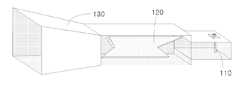
도 1은 일반적인 원형편파용 혼 안테나의 구조도이다.1 is a structural diagram of a general circular polarization horn antenna.
도 1에 도시된 바와 같이, 일반적인 원형편파용 혼 안테나는, 혼 안테나로 전력을 전달하는 급전기(110)를 포함하여, 원형편파를 발생시키는 원형편파기(120) 및 도파관 혼(130) 등의 복잡한 구조를 가지게 된다.As shown in FIG. 1, a general circular polarization horn antenna includes a
이러한 구조적인 복잡함으로 인하여, 기존의 원형편파용 혼 안테나는 각 부분의 설계와 제작상의 어려움이 따랐으며, 이러한 문제는 제작단가를 높이는 중요한 요인으로 작용하게 되는 문제점이 있다.Due to this structural complexity, the conventional circular polarization horn antenna has been difficult to design and manufacture of each part, there is a problem that this problem acts as an important factor to increase the manufacturing cost.
또한, 상술한 구조적인 문제점으로 인하여, 안테나의 물리적 크기를 증대시킴으로써, 고이득 배열안테나를 이용하는 다양한 안테나 시스템에 적용되지 못하는 제한이 있었다.In addition, due to the above-described structural problems, by increasing the physical size of the antenna, there is a limitation that can not be applied to various antenna systems using a high gain array antenna.
상기와 같은 문제점을 해결하기 위하여, 미합중국 특허 제672,707호가 개시되어 있다.In order to solve the above problems, US Patent No. 672,707 is disclosed.
상기 특허는, 선형편파를 방사하는 급전용 소형 혼과 파라볼릭 형태를 갖는 방사 혼을 유전체기판에 일체형으로 제작하여, 설치공간을 줄일 수 있도록 하였다.The patent has been made to produce a small horn for feeding linearly polarized radiation and a radiation horn having a parabolic shape integrally on the dielectric substrate, to reduce the installation space.
그러나, 상기 특허는, 직선편파가 방사되게 되므로, 원형편파의 안테나 시스템에는 적용할 수 없는 문제점이 있다.However, the patent has a problem that can not be applied to the antenna system of circular polarization because the linear polarization is radiated.
본 발명은 상기한 바와 같은 문제점을 해결하기 위하여 제안된 것으로, 평판형 방사소자를 이용하여 혼 안테나에 전력을 급전하는 급전부의 역할과 원형편파를 유발하는 원형편파기의 역할을 대체함으로써, 그 구조의 단순화 및 소형화를 이룰 수 있도록 하는, 평판형 방사소자를 이용한 원형편파용 혼 안테나를 제공하는데 그 목적이 있다.
The present invention has been proposed to solve the above problems, by replacing the role of the feeder for feeding power to the horn antenna and the role of the circular polarizer to induce circular polarization by using a flat plate radiating element, It is an object of the present invention to provide a circularly polarized horn antenna using a flat plate radiating element, which can achieve a simplified structure and a smaller size.
상기 목적을 달성하기 위한 본 발명은, 평판형 방사소자를 이용한 원형편파용 혼 안테나에 있어서, 혼으로 전력을 급전하고, 원형편파를 발생시키기 위한, 방사패치가 배치된 평판형 방사소자; 및 급전된 전력을 방사하기 위한 상기 혼을 포함하는 것을 특징으로 한다.According to an aspect of the present invention, there is provided a circular polarization horn antenna using a flat plate radiating element, the flat plate radiating element having a radiation patch arranged to feed power to a horn and generate circular polarization; And the horn for radiating the supplied electric power.
또한, 상기 본 발명은, 상기 평판형 방사소자와 상기 혼 사이에 배치되어, 상기 평판형 방사소자와 상기 혼 사이의 전기적인 정합을 이루기 위한 도파관을 더 포함하는 것을 특징으로 한다.In addition, the present invention is characterized in that it further comprises a waveguide disposed between the plate-shaped radiating element and the horn, to achieve electrical matching between the plate-shaped radiating element and the horn.
상술한 목적, 특징들 및 장점은 첨부된 도면과 관련한 다음의 상세한 설명을 통하여 보다 분명해 질 것이다. 우선 각 도면의 구성요소들에 참조 번호를 부가함에 있어서, 동일한 구성요소들에 한해서는 비록 다른 도면상에 표시되더라도 가능한 한 동일한 번호를 가지도록 하고 있음에 유의하여야 한다. 이하, 첨부된 도면을 참조하여 본 발명에 따른 바람직한 일실시예를 상세히 설명한다.The above objects, features and advantages will become more apparent from the following detailed description taken in conjunction with the accompanying drawings. First of all, in adding reference numerals to the components of each drawing, it should be noted that the same components have the same number as much as possible even if displayed on different drawings. Hereinafter, exemplary embodiments of the present invention will be described in detail with reference to the accompanying drawings.
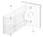
도 2는 본 발명에 따른 평판형 방사소자를 이용한 원형편파용 혼 안테나의 일실시예 구조도이다.Figure 2 is a structure diagram of an embodiment of a circular polarized horn antenna using a flat plate radiating element according to the present invention.
도 2에 도시된 바와 같이, 본 발명의 혼 안테나는, 평판형 방사소자(210) 및 혼(220)을 포함하며, 상기 혼(220)은 상기 평판형 방사소자(210)의 설명을 위하여 절단된 형태를 도시하였으나, 그 완전한 형태는 도 4를 참고하여 설명할 것이다.As shown in FIG. 2, the horn antenna of the present invention includes a planar
본 발명에 대한 보편적인 이해를 위하여, 상기 평판형 방사소자(210)로서, 모서리가 절단된 사각 마이크로스트립 원형편파용 방사패치(Corner Truncated Square Patch Radiator)를 적용하였으나, 다른 형태의 방사패치의 적용을 배재하는 것은 아니다.For the general understanding of the present invention, as the flat
상기 평판형 방사소자(210)는, 상기 혼(220)으로 전력을 급전함과 동시에, 원형편파를 발생하는 기능을 담당한다.The plate-
또한, 정사각형의 개구면을 갖는 상기 혼(220)은 상기 평판형 방사소자(210)의 그라운드와 연결되지 않는 구조를 가지며, 이로 인하여 상기 혼(220)의 내부에 상기 평판형 방사소자(210)를 삽입하고 고정해야 하는 등의 구조적인 문제에 대한 편리함을 도모할 수 있다는 부가적인 장점을 갖는다.In addition, the
도 3은 상기 도 2의 평판형 방사소자의 제 2실시예 구조도이다.3 is a structural diagram of a second embodiment of the planar radiating element of FIG. 2.
도 3에 도시된 바와 같이, 본 발명의 제 2실시예인 평판형 방사소자는, 축비대역을 확장하기 위하여, 평판형 방사패치(310)의 상단에 평판형 기생패치(320)를 배치함으로써, 이중공진을 통한 광대역 특성을 갖도록 하였다.As shown in FIG. 3, in the planar radiating element according to the second embodiment of the present invention, the planar
상기 도 2 및 상기 도 3에 예시된 평판형 방사소자의 일예 외에도, 본 발명의 혼 안테나는, 다양한 형태의 평판형 방사소자를 적용할 수 있다.In addition to the example of the planar radiating element illustrated in FIGS. 2 and 3, the horn antenna of the present invention may apply various types of planar radiating elements.
도 4는 상기 도 2의 혼의 일실시예 상세 구조도이다.4 is a detailed structural diagram of an embodiment of the horn of FIG.
도 4에 도시된 바와 같이, 본 발명의 도파관 혼은, 상기 평판형 방사소자(210)를 통하여 급전된 원형편파가 진행할 수 있도록, 정사각형의 개구면을 가지고 상기 평판형 방사소자(210)와 혼(220) 사이에서 상기 혼(220)과 일체형으로 결합된 도파관(410)을 더 포함한다.As shown in FIG. 4, the waveguide horn of the present invention has a square opening surface so that the circularly polarized wave fed through the flat plate
상기 도파관(410)은 상기 평판형 방사소자(210)와 피라미드 형태의 정사각형 개구면을 갖는 상기 혼(220) 사이의 전기적인 정합을 이루는 기능을 담당한다.The
상기 도파관(410)의 종단에는, 상기 도파관(410)을 진행하는 원형편파 전력이 자유공간으로 방사될 수 있도록 설계된 피라미드 형태의 정사각형 개구면을 갖는 상기 혼(220)이 접속되도록 배치된다.At the end of the
본 발명의 혼 안테나를 통하여, 상기 평판형 방사소자(210)로부터 여기된 원형편파 전력을 자유공간 상으로 효율적으로 전달할 수 있다.Through the horn antenna of the present invention, the circularly polarized power excited from the planar radiating
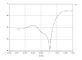
도 5는 본 발명에 따른 평판형 방사소자를 이용한 원형편파용 혼 안테나의 임피던스 정합특성을 설명하기 위한 일실시예 그래프이다.5 is a graph illustrating an embodiment of impedance matching characteristics of a circular polarization horn antenna using a flat plate radiating element according to the present invention.
도 5에 도시된 바와 같이, 상기 혼(220)의 정사각형의 개구면의 크기 및 길이를 조정함으로써, 상기 평판형 방사소자(210)로부터 여기된 원형편파 전력을 자유공간 상으로 효율적 전달할 수 있는 정합특성을 구현할 수 있음을 알 수 있다.As shown in FIG. 5, by adjusting the size and length of the square opening surface of the
도 6은 본 발명에 따른 방사소자를 이용한 원형편파용 혼 안테나의 이득 및 원형편파에 대한 축비특성을 설명하기 위한 일실시예 그래프이다.FIG. 6 is a graph for explaining the axial ratio characteristics of the gain and the circular polarization of the circularly polarized horn antenna using the radiating element according to the present invention.
도 6에 도시된 바와 같이, 본 발명의 혼 안테나는, 10%의 3dB 축비대역을 가지며, 동일대역에서 최소 9.0dBi의 이득특성을 보인다.As shown in FIG. 6, the horn antenna of the present invention has a 3 dB axial ratio band of 10% and exhibits a gain characteristic of at least 9.0 dBi in the same band.
또한, 본 발명의 혼 안테나는, 7%의 2dB 축비특성과 동일대역에서 최소 9.5dBi의 이득특성을 보임을 알 수 있다.In addition, it can be seen that the horn antenna of the present invention has a 2dB axial ratio characteristic of 7% and a gain characteristic of at least 9.5dBi in the same band.
본 발명에 따른 혼 안테나는, 상술한 바와 같이 가로와 세로의 길이가 동일한 정사각형 구조를 취하고 있으며, 일반적인 사각형 개구면을 갖는 혼 안테나의 이론적인 이득특성과 비교해 볼 때, 간단한 구조를 통하여 부가적인 손실 없이 원형편파를 발생한다는 것을 알 수 있다.The horn antenna according to the present invention has a square structure having the same length and width as described above, and compared with the theoretical gain characteristics of a horn antenna having a general rectangular opening surface, an additional loss is achieved through a simple structure. It can be seen that circular polarization is generated without.
이상에서 설명한 본 발명은 전술한 실시예 및 첨부된 도면에 의해 한정되는 것이 아니고, 본 발명의 기술적 사상을 벗어나지 않는 범위 내에서 여러 가지 치환, 변형 및 변경이 가능하다는 것이 본 발명이 속하는 기술분야에서 통상의 지식을 가진 자에게 있어 명백할 것이다.The present invention described above is not limited to the above-described embodiments and the accompanying drawings, and various substitutions, modifications, and changes are possible in the art without departing from the technical spirit of the present invention. It will be clear to those of ordinary knowledge.
상기한 바와 같은 본 발명은, 원형편파용 혼 안테나에 평판형 방사소자를 적용함으로써, 일반적인 원형편파용 혼 안테나 구조에서의 급전기와 원형편파기의 기능을 동시에 구현할 수 있다. The present invention as described above, by applying a flat plate radiating element to the circular polarization horn antenna, it is possible to implement the functions of the feeder and circular polarizer in the general circular polarization horn antenna structure at the same time.
또한, 본 발명은, 일반적인 혼 안테나 구조에서 상당한 부분을 차지하는 원형편파기를 제거함으로써, 원형편파용 혼 안테나를 소형화할 수 있는 효과가 있으며, 설계상의 편리함을 제공함과 동시에 제작비용을 줄일 수 있는 효과가 있다.In addition, the present invention has the effect of miniaturizing the circular polarized horn antenna by eliminating the circular polarizer occupying a significant portion of the general horn antenna structure, and provides the convenience of design and at the same time reduce the manufacturing cost have.
또한, 본 발명은, 동일한 구조를 도파관에 적용함으로써, 간단하게 도파관의 직렬 급전구조를 구현할 수 있도록 하는 효과가 있다.In addition, the present invention, by applying the same structure to the waveguide, there is an effect that it is possible to simply implement a series feed structure of the waveguide.
또한, 본 발명은, 마이크로스트립 안테나의 급전구조를 달리함으로써, 병렬 급전구조에도 용이하게 적용할 수 있는 등의 급전구조의 다양화를 도모할 수 있는 효과가 있다.In addition, the present invention has an effect of diversifying the feeding structure such as being easily applied to the parallel feeding structure by changing the feeding structure of the microstrip antenna.
Claims (7)
Translated fromKoreanPriority Applications (2)
| Application Number | Priority Date | Filing Date | Title |
|---|---|---|---|
| KR1020030083323AKR100626666B1 (en) | 2003-11-22 | 2003-11-22 | Circularly Polarized Horn Antenna Using Flat Radiating Element |
| US10/994,006US7212162B2 (en) | 2003-11-22 | 2004-11-19 | Horn antenna for circular polarization using planar radiator |
Applications Claiming Priority (1)
| Application Number | Priority Date | Filing Date | Title |
|---|---|---|---|
| KR1020030083323AKR100626666B1 (en) | 2003-11-22 | 2003-11-22 | Circularly Polarized Horn Antenna Using Flat Radiating Element |
Publications (2)
| Publication Number | Publication Date |
|---|---|
| KR20050049630A KR20050049630A (en) | 2005-05-27 |
| KR100626666B1true KR100626666B1 (en) | 2006-09-22 |
Family
ID=34587983
Family Applications (1)
| Application Number | Title | Priority Date | Filing Date |
|---|---|---|---|
| KR1020030083323AExpired - Fee RelatedKR100626666B1 (en) | 2003-11-22 | 2003-11-22 | Circularly Polarized Horn Antenna Using Flat Radiating Element |
Country Status (2)
| Country | Link |
|---|---|
| US (1) | US7212162B2 (en) |
| KR (1) | KR100626666B1 (en) |
Families Citing this family (30)
| Publication number | Priority date | Publication date | Assignee | Title |
|---|---|---|---|---|
| KR100603604B1 (en)* | 2004-12-16 | 2006-07-24 | 한국전자통신연구원 | Flat-top element pattern forming apparatus using circularly polarized microstrip patch |
| KR100687908B1 (en)* | 2005-03-16 | 2007-02-27 | (주) 아이엔텍 | Pyramid Horn Antenna for Radar Detector Using Trapezoidal Waveguide |
| US7750859B2 (en)* | 2006-01-12 | 2010-07-06 | Lockheed Martin Corporation | Generic pick-up horn for high power thermal vacuum testing of satellite payloads at multiple frequency bands and at multiple polarizations |
| US7598919B2 (en)* | 2006-01-12 | 2009-10-06 | Lockheed Martin Corporation | Pick-up horn for high power thermal vacuum testing of spacecraft payloads |
| AU2011201657A1 (en)* | 2008-10-15 | 2011-05-12 | Andrew Llc | Wideband radiating elements |
| EP2351149A4 (en)* | 2008-10-15 | 2012-12-26 | Andrew Llc | Wideband radiating elements |
| US9930592B2 (en) | 2013-02-19 | 2018-03-27 | Mimosa Networks, Inc. | Systems and methods for directing mobile device connectivity |
| US9179336B2 (en) | 2013-02-19 | 2015-11-03 | Mimosa Networks, Inc. | WiFi management interface for microwave radio and reset to factory defaults |
| WO2014137370A1 (en) | 2013-03-06 | 2014-09-12 | Mimosa Networks, Inc. | Waterproof apparatus for cables and cable interfaces |
| US10742275B2 (en) | 2013-03-07 | 2020-08-11 | Mimosa Networks, Inc. | Quad-sector antenna using circular polarization |
| US9191081B2 (en) | 2013-03-08 | 2015-11-17 | Mimosa Networks, Inc. | System and method for dual-band backhaul radio |
| CN103779662A (en)* | 2013-05-10 | 2014-05-07 | 贵州振华天通设备有限公司 | 5GHz feed source structure and fabrication method thereof |
| US9295103B2 (en) | 2013-05-30 | 2016-03-22 | Mimosa Networks, Inc. | Wireless access points providing hybrid 802.11 and scheduled priority access communications |
| US10938110B2 (en) | 2013-06-28 | 2021-03-02 | Mimosa Networks, Inc. | Ellipticity reduction in circularly polarized array antennas |
| US9001689B1 (en) | 2014-01-24 | 2015-04-07 | Mimosa Networks, Inc. | Channel optimization in half duplex communications systems |
| US9998246B2 (en) | 2014-03-13 | 2018-06-12 | Mimosa Networks, Inc. | Simultaneous transmission on shared channel |
| US10958332B2 (en) | 2014-09-08 | 2021-03-23 | Mimosa Networks, Inc. | Wi-Fi hotspot repeater |
| WO2017123558A1 (en)* | 2016-01-11 | 2017-07-20 | Mimosa Networks, Inc. | Printed circuit board mounted antenna and waveguide interface |
| US11251539B2 (en) | 2016-07-29 | 2022-02-15 | Airspan Ip Holdco Llc | Multi-band access point antenna array |
| KR101887417B1 (en)* | 2017-08-14 | 2018-09-10 | 주식회사 에스원 | Horn-Reflector Antenna with Low Sidelobe |
| US20190165488A1 (en)* | 2017-11-30 | 2019-05-30 | T-Mobile Usa, Inc. | Dual circular polarization diversity scheme for microwave link |
| US10511074B2 (en) | 2018-01-05 | 2019-12-17 | Mimosa Networks, Inc. | Higher signal isolation solutions for printed circuit board mounted antenna and waveguide interface |
| US11069986B2 (en) | 2018-03-02 | 2021-07-20 | Airspan Ip Holdco Llc | Omni-directional orthogonally-polarized antenna system for MIMO applications |
| US11289821B2 (en) | 2018-09-11 | 2022-03-29 | Air Span Ip Holdco Llc | Sector antenna systems and methods for providing high gain and high side-lobe rejection |
| KR102152187B1 (en)* | 2019-06-25 | 2020-09-04 | 주식회사 센서뷰 | Horn Antenna Device for Transforming into Circular Polarization |
| KR102189242B1 (en)* | 2020-02-18 | 2020-12-09 | 국방과학연구소 | Input/output feed antenna apparatus |
| CN111864397B (en)* | 2020-08-17 | 2024-11-05 | 中国电子科技集团公司第五十四研究所 | A horn antenna |
| CN112713405B (en)* | 2020-12-18 | 2024-10-29 | 中国电子科技集团公司第五十四研究所 | Coplanar waveguide feed horn antenna |
| KR102370147B1 (en)* | 2021-01-21 | 2022-03-07 | 주식회사 센서뷰 | Horn Antenna Using PCB Feeding |
| KR102742887B1 (en)* | 2023-05-18 | 2024-12-16 | 한라아이엠에스 주식회사 | Hybrid antenna combining patch antenna and horn antenna |
Family Cites Families (17)
| Publication number | Priority date | Publication date | Assignee | Title |
|---|---|---|---|---|
| US4051476A (en)* | 1976-04-01 | 1977-09-27 | Raytheon Company | Parabolic horn antenna with microstrip feed |
| JPS5437556A (en) | 1977-08-30 | 1979-03-20 | Mitsubishi Electric Corp | Horn antenna |
| US4423422A (en)* | 1981-08-10 | 1983-12-27 | Andrew Corporation | Diagonal-conical horn-reflector antenna |
| FR2582865B1 (en)* | 1985-06-04 | 1987-07-31 | Labo Electronique Physique | MICROWAVE UNIT MODULES AND MICROWAVE ANTENNA COMPRISING SUCH MODULES |
| JPS62118613A (en) | 1985-11-19 | 1987-05-30 | Nippon Telegr & Teleph Corp <Ntt> | Circularly polarized wave horn antenna |
| US5214394A (en)* | 1991-04-15 | 1993-05-25 | Rockwell International Corporation | High efficiency bi-directional spatial power combiner amplifier |
| US5210542A (en)* | 1991-07-03 | 1993-05-11 | Ball Corporation | Microstrip patch antenna structure |
| FR2698212B1 (en)* | 1992-11-16 | 1994-12-30 | Alcatel Espace | Radiant elementary source for array antenna and radiating sub-assembly comprising such sources. |
| JP3225490B2 (en)* | 1993-06-17 | 2001-11-05 | 本田技研工業株式会社 | Dielectric antenna |
| US5608263A (en)* | 1994-09-06 | 1997-03-04 | The Regents Of The University Of Michigan | Micromachined self packaged circuits for high-frequency applications |
| KR0140601B1 (en) | 1995-03-31 | 1998-07-01 | 배순훈 | Polarization receiver |
| US6320509B1 (en)* | 1998-03-16 | 2001-11-20 | Intermec Ip Corp. | Radio frequency identification transponder having a high gain antenna configuration |
| KR100322119B1 (en)* | 1998-07-31 | 2002-05-09 | 윤종용 | Planar broadband dipole antenna for linearly polariged waves |
| JP2001168632A (en) | 1999-12-13 | 2001-06-22 | Nippon Antenna Co Ltd | Horn antenna and primary radiator |
| US6762729B2 (en)* | 2001-09-03 | 2004-07-13 | Houkou Electric Co., Ltd. | Slotted bow tie antenna with parasitic element, and slotted bow tie array antenna with parasitic element |
| TW518802B (en)* | 2001-10-03 | 2003-01-21 | Accton Technology Corp | Broadband circularly polarized panel antenna |
| US6788258B2 (en)* | 2002-04-09 | 2004-09-07 | Arc Wireless Solutions, Inc. | Partially shared antenna aperture |
- 2003
- 2003-11-22KRKR1020030083323Apatent/KR100626666B1/ennot_activeExpired - Fee Related
- 2004
- 2004-11-19USUS10/994,006patent/US7212162B2/ennot_activeExpired - Fee Related
Also Published As
| Publication number | Publication date |
|---|---|
| US20050110695A1 (en) | 2005-05-26 |
| US7212162B2 (en) | 2007-05-01 |
| KR20050049630A (en) | 2005-05-27 |
Similar Documents
| Publication | Publication Date | Title |
|---|---|---|
| KR100626666B1 (en) | Circularly Polarized Horn Antenna Using Flat Radiating Element | |
| US8552920B2 (en) | Patch antenna synchronously generating linearly polarized wave and circularly polarized wave and generating method thereof | |
| CN111106451B (en) | A one-dimensional electronically steered beam scanning circularly polarized antenna and its control method | |
| US20110128201A1 (en) | Circularly polarized antenna in wireless communication system and method for manufacturing the same | |
| JP2005086801A (en) | High gain wideband microstrip patch antenna for transmission / reception and array antenna in which this is arranged | |
| JPH04271605A (en) | Feeder device for radiation element operated by two polarizes waves | |
| JP7288087B2 (en) | Dual Polarized Antenna Using Shifted Series Feed | |
| US11437736B2 (en) | Broadband antenna having polarization dependent output | |
| Nkimbeng et al. | Low-profile wideband unidirectional circularly polarized metasurface-based bowtie slot antenna | |
| KR100449846B1 (en) | Circular Polarized Microstrip Patch Antenna and Array Antenna arraying it for Sequential Rotation Feeding | |
| CN201252154Y (en) | Broadband double-line polarized dipole aerial array | |
| Huang et al. | A metasurface‐enabled wideband high‐gain dual‐circularly‐polarized Fabry‐Perot resonator antenna | |
| CN114614249B (en) | A broadband circularly polarized magnetoelectric dipole transmission array antenna | |
| JP4070784B2 (en) | Antenna and array antenna | |
| CN112201964B (en) | Reflection transmission array antenna and construction method thereof | |
| KR100991818B1 (en) | High Efficiency Wideband Circularly Polarized Patch Antenna | |
| JP2000124734A (en) | Flat array antenna | |
| JPS62210703A (en) | planar antenna | |
| Dogan | A wide band, dual polarized patch antenna for wide angle scanning phased arrays | |
| JP5858844B2 (en) | Antenna device | |
| JP3068149B2 (en) | Microstrip array antenna | |
| JP3038205B1 (en) | Waveguide-fed planar antenna | |
| JPH08274539A (en) | Microstrip array antenna device | |
| JP2006014152A (en) | Planar antenna | |
| KR20050065958A (en) | Multi-resonance antenna |
Legal Events
| Date | Code | Title | Description |
|---|---|---|---|
| A201 | Request for examination | ||
| PA0109 | Patent application | St.27 status event code:A-0-1-A10-A12-nap-PA0109 | |
| PA0201 | Request for examination | St.27 status event code:A-1-2-D10-D11-exm-PA0201 | |
| PG1501 | Laying open of application | St.27 status event code:A-1-1-Q10-Q12-nap-PG1501 | |
| E902 | Notification of reason for refusal | ||
| PE0902 | Notice of grounds for rejection | St.27 status event code:A-1-2-D10-D21-exm-PE0902 | |
| T11-X000 | Administrative time limit extension requested | St.27 status event code:U-3-3-T10-T11-oth-X000 | |
| T11-X000 | Administrative time limit extension requested | St.27 status event code:U-3-3-T10-T11-oth-X000 | |
| T11-X000 | Administrative time limit extension requested | St.27 status event code:U-3-3-T10-T11-oth-X000 | |
| T11-X000 | Administrative time limit extension requested | St.27 status event code:U-3-3-T10-T11-oth-X000 | |
| AMND | Amendment | ||
| E13-X000 | Pre-grant limitation requested | St.27 status event code:A-2-3-E10-E13-lim-X000 | |
| P11-X000 | Amendment of application requested | St.27 status event code:A-2-2-P10-P11-nap-X000 | |
| P13-X000 | Application amended | St.27 status event code:A-2-2-P10-P13-nap-X000 | |
| E601 | Decision to refuse application | ||
| PE0601 | Decision on rejection of patent | St.27 status event code:N-2-6-B10-B15-exm-PE0601 | |
| J201 | Request for trial against refusal decision | ||
| PJ0201 | Trial against decision of rejection | St.27 status event code:A-3-3-V10-V11-apl-PJ0201 | |
| AMND | Amendment | ||
| P11-X000 | Amendment of application requested | St.27 status event code:A-2-2-P10-P11-nap-X000 | |
| P13-X000 | Application amended | St.27 status event code:A-2-2-P10-P13-nap-X000 | |
| PB0901 | Examination by re-examination before a trial | St.27 status event code:A-6-3-E10-E12-rex-PB0901 | |
| B701 | Decision to grant | ||
| PB0701 | Decision of registration after re-examination before a trial | St.27 status event code:A-3-4-F10-F13-rex-PB0701 | |
| GRNT | Written decision to grant | ||
| PR0701 | Registration of establishment | St.27 status event code:A-2-4-F10-F11-exm-PR0701 | |
| PR1002 | Payment of registration fee | St.27 status event code:A-2-2-U10-U11-oth-PR1002 Fee payment year number:1 | |
| PG1601 | Publication of registration | St.27 status event code:A-4-4-Q10-Q13-nap-PG1601 | |
| PN2301 | Change of applicant | St.27 status event code:A-5-5-R10-R13-asn-PN2301 St.27 status event code:A-5-5-R10-R11-asn-PN2301 | |
| PR1001 | Payment of annual fee | St.27 status event code:A-4-4-U10-U11-oth-PR1001 Fee payment year number:4 | |
| PR1001 | Payment of annual fee | St.27 status event code:A-4-4-U10-U11-oth-PR1001 Fee payment year number:5 | |
| PN2301 | Change of applicant | St.27 status event code:A-5-5-R10-R11-asn-PN2301 | |
| PN2301 | Change of applicant | St.27 status event code:A-5-5-R10-R14-asn-PN2301 | |
| PR1001 | Payment of annual fee | St.27 status event code:A-4-4-U10-U11-oth-PR1001 Fee payment year number:6 | |
| FPAY | Annual fee payment | Payment date:20120809 Year of fee payment:7 | |
| PR1001 | Payment of annual fee | St.27 status event code:A-4-4-U10-U11-oth-PR1001 Fee payment year number:7 | |
| PN2301 | Change of applicant | St.27 status event code:A-5-5-R10-R11-asn-PN2301 | |
| PN2301 | Change of applicant | St.27 status event code:A-5-5-R10-R14-asn-PN2301 | |
| FPAY | Annual fee payment | Payment date:20130802 Year of fee payment:8 | |
| PR1001 | Payment of annual fee | St.27 status event code:A-4-4-U10-U11-oth-PR1001 Fee payment year number:8 | |
| PR1001 | Payment of annual fee | St.27 status event code:A-4-4-U10-U11-oth-PR1001 Fee payment year number:9 | |
| PN2301 | Change of applicant | St.27 status event code:A-5-5-R10-R13-asn-PN2301 St.27 status event code:A-5-5-R10-R11-asn-PN2301 | |
| FPAY | Annual fee payment | Payment date:20150817 Year of fee payment:10 | |
| PR1001 | Payment of annual fee | St.27 status event code:A-4-4-U10-U11-oth-PR1001 Fee payment year number:10 | |
| L13-X000 | Limitation or reissue of ip right requested | St.27 status event code:A-2-3-L10-L13-lim-X000 | |
| U15-X000 | Partial renewal or maintenance fee paid modifying the ip right scope | St.27 status event code:A-4-4-U10-U15-oth-X000 | |
| FPAY | Annual fee payment | Payment date:20160826 Year of fee payment:11 | |
| PR1001 | Payment of annual fee | St.27 status event code:A-4-4-U10-U11-oth-PR1001 Fee payment year number:11 | |
| R18-X000 | Changes to party contact information recorded | St.27 status event code:A-5-5-R10-R18-oth-X000 | |
| FPAY | Annual fee payment | Payment date:20170904 Year of fee payment:12 | |
| PR1001 | Payment of annual fee | St.27 status event code:A-4-4-U10-U11-oth-PR1001 Fee payment year number:12 | |
| LAPS | Lapse due to unpaid annual fee | ||
| PC1903 | Unpaid annual fee | St.27 status event code:A-4-4-U10-U13-oth-PC1903 Not in force date:20180915 Payment event data comment text:Termination Category : DEFAULT_OF_REGISTRATION_FEE | |
| PC1903 | Unpaid annual fee | St.27 status event code:N-4-6-H10-H13-oth-PC1903 Ip right cessation event data comment text:Termination Category : DEFAULT_OF_REGISTRATION_FEE Not in force date:20180915 |