KR100624877B1 - Surface treatment method of wet surface heat exchanger for improving wettability - Google Patents
Surface treatment method of wet surface heat exchanger for improving wettabilityDownload PDFInfo
- Publication number
- KR100624877B1 KR100624877B1KR1020020039406AKR20020039406AKR100624877B1KR 100624877 B1KR100624877 B1KR 100624877B1KR 1020020039406 AKR1020020039406 AKR 1020020039406AKR 20020039406 AKR20020039406 AKR 20020039406AKR 100624877 B1KR100624877 B1KR 100624877B1
- Authority
- KR
- South Korea
- Prior art keywords
- heat exchanger
- hydrophilic
- porous structure
- wet
- treatment method
- Prior art date
- Legal status (The legal status is an assumption and is not a legal conclusion. Google has not performed a legal analysis and makes no representation as to the accuracy of the status listed.)
- Expired - Lifetime
Links
Images


Classifications
- F—MECHANICAL ENGINEERING; LIGHTING; HEATING; WEAPONS; BLASTING
- F28—HEAT EXCHANGE IN GENERAL
- F28F—DETAILS OF HEAT-EXCHANGE AND HEAT-TRANSFER APPARATUS, OF GENERAL APPLICATION
- F28F13/00—Arrangements for modifying heat-transfer, e.g. increasing, decreasing
- F28F13/18—Arrangements for modifying heat-transfer, e.g. increasing, decreasing by applying coatings, e.g. radiation-absorbing, radiation-reflecting; by surface treatment, e.g. polishing
- F—MECHANICAL ENGINEERING; LIGHTING; HEATING; WEAPONS; BLASTING
- F28—HEAT EXCHANGE IN GENERAL
- F28D—HEAT-EXCHANGE APPARATUS, NOT PROVIDED FOR IN ANOTHER SUBCLASS, IN WHICH THE HEAT-EXCHANGE MEDIA DO NOT COME INTO DIRECT CONTACT
- F28D5/00—Heat-exchange apparatus having stationary conduit assemblies for one heat-exchange medium only, the media being in contact with different sides of the conduit wall, using the cooling effect of natural or forced evaporation
- F28D5/02—Heat-exchange apparatus having stationary conduit assemblies for one heat-exchange medium only, the media being in contact with different sides of the conduit wall, using the cooling effect of natural or forced evaporation in which the evaporating medium flows in a continuous film or trickles freely over the conduits
- F—MECHANICAL ENGINEERING; LIGHTING; HEATING; WEAPONS; BLASTING
- F28—HEAT EXCHANGE IN GENERAL
- F28F—DETAILS OF HEAT-EXCHANGE AND HEAT-TRANSFER APPARATUS, OF GENERAL APPLICATION
- F28F19/00—Preventing the formation of deposits or corrosion, e.g. by using filters or scrapers
- F28F19/02—Preventing the formation of deposits or corrosion, e.g. by using filters or scrapers by using coatings, e.g. vitreous or enamel coatings
- F—MECHANICAL ENGINEERING; LIGHTING; HEATING; WEAPONS; BLASTING
- F28—HEAT EXCHANGE IN GENERAL
- F28F—DETAILS OF HEAT-EXCHANGE AND HEAT-TRANSFER APPARATUS, OF GENERAL APPLICATION
- F28F2245/00—Coatings; Surface treatments
- F28F2245/02—Coatings; Surface treatments hydrophilic
Landscapes
- Engineering & Computer Science (AREA)
- Physics & Mathematics (AREA)
- Thermal Sciences (AREA)
- Mechanical Engineering (AREA)
- General Engineering & Computer Science (AREA)
- Application Of Or Painting With Fluid Materials (AREA)
- Heat-Exchange Devices With Radiators And Conduit Assemblies (AREA)
Abstract
Translated fromKoreanDescription
Translated fromKorean도 1은 습표면 열교환기의 개략도이다.1 is a schematic diagram of a wet surface heat exchanger.
도 2는 종래의 습표면 열교환기 표면에서의 물방울 분포를 나타낸 도면이다.2 is a view showing the distribution of water droplets on the surface of a conventional wet surface heat exchanger.
도 3은 본 발명에 따라 고체 입자와 친수성 바인더를 이용하여 표면 처리한 후의 결과를 나타낸 개략도이다.3 is a schematic view showing the results after surface treatment using solid particles and a hydrophilic binder according to the present invention.
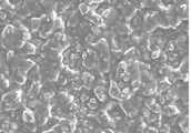
도 4는 본 발명의 실시예에 따라 고체 입자와 친수성 바인더에 의한 다공구조의 형성 상태를 나타낸 도면이다.4 is a view showing a state in which a porous structure is formed by solid particles and a hydrophilic binder according to an embodiment of the present invention.
도 5는 본 발명의 실시예에 따라 바인더의 점도가 과도하게 큰 경우의 코팅 표면 상태를 나타낸 도면이다.5 is a view showing a coating surface state when the viscosity of the binder is excessively large according to an embodiment of the present invention.
도 6은 본 발명의 실시예에 따라 바인더의 점도가 적절한 경우의 코팅 표면 상태를 나타낸 도면이다.6 is a view showing a coating surface state when the viscosity of the binder in accordance with an embodiment of the present invention.
도 7은 본 발명에 따라 표면 부식 후 친수성 처리에 의한 다공구조의 형성 상태를 나타낸 도면이다.7 is a view showing a state of formation of the porous structure by hydrophilic treatment after surface corrosion in accordance with the present invention.
도 8은 본 발명의 실시예에 따라 친수성 다공구조의 표면처리에 의한 물의 퍼짐성 향상 상태를 나타낸 도면이다.8 is a view showing a state of improving the spreadability of water by the surface treatment of the hydrophilic porous structure according to an embodiment of the present invention.
< 도면의 주요부분에 대한 부호의 설명 ><Description of Symbols for Major Parts of Drawings>
1 : 열교환기2 : 표면1: heat exchanger 2: surface
3 : 물공급기구4 : 물3: water supply mechanism 4: water
5 : 공기의 유입 방향10 : 기공5: inflow direction of air 10: pore
11 : 미세 고체 입자12 : 친수성 바인더11: fine solid particles 12: hydrophilic binder
본 발명은 젖음성 향상을 위한 습표면 열교환기의 표면처리 방법에 관한 것이다. 보다 상세하게는 냉각탑, 증발식 응축기, 냉각기 등의 열교환기 표면을 친수성 다공구조로 변형시킴으로서 습표면의 젖음도를 획기적으로 향상시킬 수 있는 기술에 관한 것이다.The present invention relates to a surface treatment method of a wet surface heat exchanger for improving wettability. More specifically, the present invention relates to a technology that can significantly improve the wetness of the wet surface by transforming the surface of heat exchangers such as cooling towers, evaporative condensers, coolers into hydrophilic porous structures.
습표면 열교환기는 도 1에 도시된 바와 같이 물 공급기구(3)로부터 열교환기(1)의 표면(2)에 도포된 물(4)이 증발하는 것에 의하여 열교환기 내부의 유체를 냉각하는 기술로서 온도차만에 의존하는 열교환기에 비하여 냉각 성능을 크게 향상시킬 수 있다. 부호 5는 공기의 유입 방향을 나타낸다.The wet surface heat exchanger is a technique for cooling the fluid inside the heat exchanger by evaporation of
이러한 습표면 열교환기는 증발식 냉각기, 증발식 응축기, 냉각탑 등의 여러 가지 응용분야에서 수 많은 기술이 개발되었으나, 습표면 열교환기의 탁월한 잠재적인 냉각성능과 지금까지 제안된 수많은 기술들에도 불구하고 습표면 열교환기의 실질적인 적용은 상당히 제한적인 분야에만 머물고 있다.These wet surface heat exchangers have been developed with numerous technologies in various applications such as evaporative coolers, evaporative condensers, cooling towers, etc., but despite the excellent potential cooling performance of wet surface heat exchangers and numerous technologies proposed so far, The practical application of surface heat exchangers remains only in a very limited field.
그 근본적인 이유로는 열교환기의 표면(2)에 도포된 물(4)이 얇은 수막을 이 루어 열교환기의 표면을 덮는 대신, 도 2에 도시된 물방울의 형태(6)로 존재하거나 열교환기의 표면을 타고 흘러내려 버리기 때문에 열교환기 표면의 젖음도가 상당히 낮아 물의 실제 증발량이 상당히 작고, 결과적으로 증발 냉각 효과가 기대되는 것보다 훨씬 작기 때문이다.The basic reason is that the
통상적으로 젖음도를 향상시키기 위하여 실제 증발량 보다 훨씬 많은 수량을 공급하게 되는데, 이렇게 과도하게 공급된 액체는 액체가 공기의 흐름을 막고 압력손실을 증가시켜 공기의 유량을 감소시키게 된다. 경우에 따라서는 증발 냉각에 의한 냉각성능 향상의 효과 보다 유량 감소에 의한 성능저하의 영향이 커서 결과적으로는 열교환기 성능이 감소하는 경우가 발생하기도 한다.Typically, the amount of water supplied is much higher than the actual amount of evaporation to improve the wettability. This excessively supplied liquid causes the liquid to block the flow of air and increase the pressure loss, thereby reducing the air flow rate. In some cases, the effect of deterioration due to the decrease in flow rate is greater than the effect of improving the cooling performance by evaporative cooling, and as a result, the heat exchanger performance may decrease.
이와 관련된 다수의 공지된 기술을 살펴보면, 열교환기의 표면을 친수성 처리하는 기술(US 5,813,452, US 6,368,671B1)이 에어컨의 증발기 등에 적용되고 있는데, 이 기술은 증발기 표면에 응축된 물방울이 잘 흘러내리도록 고안된 것이다.Looking at a number of known techniques related to this, the technique of hydrophilic treatment of the surface of the heat exchanger (US 5,813,452, US 6,368,671B1) is applied to the evaporator of the air conditioner, such that the condensed water droplets on the surface of the evaporator flows well It is designed.
이는 습표면 열교환기의 표면을 친수성 처리하면 물방울의 접촉각이 작아지기는 하지만, 경사진 표면에서는 얇은 수막(thin water film)이 아닌 리블렛(rivulet)의 형태를 이루며 흘러내리기 때문에 표면의 젖음도는 크게 향상되지 않는다.The hydrophilic treatment of the surface of the wet surface heat exchanger decreases the contact angle of the water droplets, but on the inclined surface it flows down in the form of a riblet rather than a thin water film. It doesn't improve much.
또한, 열교환기의 표면에 가는 홈을 가공하거나(US 4,461,733, US 4,566,290), 흡습성 재질을 부착(US 6,101,823, US 6,286,325B1)함으로써 젖음성(wettability)을 향상시키는 기술은 제작 공정상 단순한 형상에만 적용이 가능하여 열전달 면적을 넓히기 위하여 복잡한 형상의 다수의 핀(fin)이 적용되는 일 반적인 열교환기에는 적용이 불가능한 단점이 있다.In addition, the technology to improve wettability by processing grooves on the surface of the heat exchanger (US 4,461,733, US 4,566,290) or by attaching a hygroscopic material (US 6,101,823, US 6,286,325B1) is applicable only to simple shapes in the manufacturing process. There is a drawback that it is impossible to apply to a general heat exchanger in which a plurality of fins of a complicated shape are applied to increase the heat transfer area.
또한, 열교환기 표면의 젖음도를 향상시키기 위하여 열교환기 표면에 물을 균일하게 도포하기 위한 물공급 분배장치(US 4,933,117, US 5,377,500, US 5,605,052, US 5,701,748)가 고안되었다.In addition, a water supply distribution device (US 4,933,117, US 5,377,500, US 5,605,052, US 5,701,748) has been devised to uniformly apply water to the heat exchanger surface in order to improve the wettability of the heat exchanger surface.
이들은 대부분 균일한 도포를 위하여 작은 직경의 노즐을 채택하고 있어 물을 고압으로 토출시키기 위한 펌프를 필요로 하거나, 노즐이 오염물질에 의하여 막히는 일이 생기기 쉬운 단점이 있다.Most of them employ a nozzle of a small diameter for uniform application and require a pump for discharging water at a high pressure, or the nozzle is likely to be clogged by contaminants.
더욱이 물공급 분배장치에 직접적으로 노출된 열교환기 표면에는 물방울이 균일하게 도포되더라도 표면이 친수성이 아니면 물방울 형태를 그대로 유지하여 유동손실을 증가시키게 되고, 친수성이면 흘러내리면서 리블렛 형태를 이루게 되어 결과적으로는 젖음도가 크게 향상되지는 않는다.Moreover, even if water droplets are uniformly applied on the surface of the heat exchanger directly exposed to the water supply distribution device, if the surface is not hydrophilic, the water droplets remain intact to increase the flow loss. Wetness does not significantly improve.
따라서 본 발명은 상기한 문제점을 해결하기 위한 것으로서, 본 발명의 목적은 열교환기의 표면을 친수성 다공성 물질로 코팅하거나, 표면을 거칠게 부식시킨 뒤 친수성 처리하여 표면을 친수성 다공구조로 변환함으로서 종래의 습표면 열교환기의 문제점인 표면의 젖음성(wettability)을 향상시킬 수 있으며, 열교환기의 형상에 관계없이 적용할 수 있는 표면처리 방법을 제공하는 데 있다.Therefore, the present invention is to solve the above problems, an object of the present invention is to coat the surface of the heat exchanger with a hydrophilic porous material, or roughly corroded the surface and then hydrophilic treatment to convert the surface into a hydrophilic porous structure of the conventional wet It is possible to improve the wettability of the surface, which is a problem of the surface heat exchanger, and to provide a surface treatment method that can be applied regardless of the shape of the heat exchanger.
이는 다공구조에서의 모세관력(capillary force)에 의해 증발수의 퍼짐성을 향상시키고, 다공구조 내에 증발수를 보유함으로써 궁극적으로 표면의 젖음성을 획기적으로 향상시킬 수 있다.This improves the spreadability of the evaporated water by capillary force in the porous structure, and ultimately improves the wettability of the surface by retaining the evaporated water in the porous structure.
이하, 본 발명의 실시예에 대한 구성 및 그 작용을 첨부한 도면을 참조하면서 상세히 설명하기로 한다.Hereinafter, with reference to the accompanying drawings, the configuration and operation of the embodiment of the present invention will be described in detail.
본 발명에서는 열교환기 표면을 친수성 다공 구조로 변환시키기 위하여 두가지 방법을 제시하였다.In the present invention, two methods are proposed to convert the heat exchanger surface into a hydrophilic porous structure.
첫 번째 방법은 도 3에 도시된 바와 같이, 미세 고체 입자(11)를 친수성 바인더(binder)(12)와 혼합하여 스프레이(spray)나 딥핑(dipping) 등의 방법으로 표면(2)에 도포한 뒤 큐어링(curing) 과정을 거침으로써 열교환기 표면(2)에 상기 미세 고체 입자(11)와 상기 친수성 바인더(12)에 의해 적층된 기공(10)이 형성되도록 친수성 다공구조를 코팅하는 방법이다.In the first method, as shown in FIG. 3, the fine
도 4는 상기한 방법에 의하여 처리된 열교환기 표면의 800배 확대 사진으로서 다공구조의 기공(10) 크기가 너무 작으면 물의 표면장력 때문에 다공구조 속으로 물이 침투하지 못하게 되며, 이와 반대로 기공이 너무 크면 모세관력이 작아져 물의 퍼짐성이 나빠지게 되므로 기공의 크기를 적절하게 조절하는 것이 필요하다.4 is an enlarged 800 times photograph of the surface of the heat exchanger treated by the above method, if the
이 때, 상기 기공의 크기에 큰 영향을 미치는 것은 고체 입자의 크기로 입자의 크기가 10 ~ 100 ㎛ 인 경우가 가장 적합하며, 입자 크기가 균일할수록 다공도(porosity)를 크게 할 수 있어 다공구조 안에 충분한 양의 물을 보유할 수 있어 유리하다.At this time, it is most appropriate that the size of the particles to have a large effect on the size of the pore as the size of the solid particles, the particle size is 10 ~ 100 ㎛, the more uniform the particle size can increase the porosity (porosity) in the porous structure It is advantageous to have a sufficient amount of water.
친수성 바인더의 점도가 높으면 도 5에 나타낸 바와 같이 고체 입자가 바인더 속에 묻혀 결과적으로 고체입자 사이가 바인더로 채워지는 형태가 되어 큐어링 과정 이후 다공구조를 얻을 수 없으며, 바인더의 점도가 너무 낮으면 표면에 도포 시 표면에서 흘러내려 코팅이 생성되지 않는다. 바인더의 점도는 용재(solvent)의 양을 적절히 제어함으로써 조절할 수 있다. 도 6은 바인더 점도가 적절한 경우의 코팅 표면을 나타낸 것이다.If the hydrophilic binder has a high viscosity, as shown in FIG. 5, the solid particles are buried in the binder, and the solid particles are filled with the binder. As a result, the porous structure cannot be obtained after the curing process. It does not form a coating as it flows off the surface during application. The viscosity of the binder can be adjusted by appropriately controlling the amount of solvent. 6 shows the coating surface when the binder viscosity is appropriate.
코팅의 두께가 너무 얇으면 다공구조 내에 충분한 양의 증발수를 보유할 수 없으며, 두께가 너무 두꺼우면 공기 유로가 감소하여 압력손실이 증가하고 다공층(porous layer) 자체가 열전달 저항으로 작용하여 증발냉각에 의한 효과를 감소시킬 수 있다. 코팅의 두께도 바인더의 점도를 조절하여 제어할 수 있다.If the thickness of the coating is too thin, it will not be able to hold a sufficient amount of evaporated water in the porous structure. If the thickness is too thick, the air flow will decrease and the pressure loss will increase, and the porous layer itself will act as a heat transfer resistance to evaporate. The effect by cooling can be reduced. The thickness of the coating can also be controlled by adjusting the viscosity of the binder.
두 번째 방법은 열교환기 표면을 화학적 또는 전기화학적 방법으로 부식시키거나, 물리적으로 표면의 거칠기를 증가시킨 후, 친수성 처리하는 방법이다.The second method is to corrode the heat exchanger surface by chemical or electrochemical methods, or to increase the surface roughness physically, and then to hydrophilic treatment.
이 때, 표면의 거칠기를 증가시키는 방법에서 화학적 방법으로는 크로메이트(chromate) 처리, 전기화학적 방법으로는 아노다이징(anodizing), 물리적인 방법으로는 샌드 블라스팅(sand blasting) 등의 방법이 있다.At this time, in the method of increasing the surface roughness, there is a method such as chromate treatment as a chemical method, anodizing as an electrochemical method, sand blasting as a physical method.
도 7은 상기한 방법에 의하여 처리된 열교환기 표면의 800배 확대 사진으로서 표면 거칠기의 크기는 고체입자를 코팅하는 경우의 기공의 크기와 같이 표면의 젖음성에 큰 영향을 미치며 10 ~ 100 ㎛ 인 경우가 가장 적합하다.7 is an enlarged 800 times photograph of the surface of the heat exchanger treated by the above method, and the size of the surface roughness has a great influence on the wettability of the surface, such as the size of the pores when the solid particles are coated, and has a size of 10 to 100 μm. Is the best.
표면 거칠기를 증가시킨 후, 표면을 친수성 수지를 코팅하여 친수성 처리하는 경우 친수성 수지의 점도가 너무 크면 거칠게 가공한 표면을 완전히 또는 부분적으로 덮어 거칠기를 감소시킬 수 있으므로 친수성 수지와 용재의 비율을 조정하여 점도를 적절히 조절하는 것이 필요하다.After increasing the surface roughness and hydrophilic treatment by coating the surface with a hydrophilic resin, if the viscosity of the hydrophilic resin is too large, the roughened surface may be completely or partially covered to reduce the roughness, thereby adjusting the ratio of the hydrophilic resin and the solvent. It is necessary to adjust the viscosity appropriately.
상기 표면처리 방법 중 친수성 다공구조를 코팅하는 방법에 있어서 고체 입 자와 친수성 바인더의 종류에는 제한이 없다.In the method of coating the hydrophilic porous structure of the surface treatment method, there is no limitation on the type of solid particles and the hydrophilic binder.
또한, 표면의 거칠기를 증가시킨 후, 친수성 처리하는 방법에 있어서 표면의 거칠기를 증가시키거나 친수성 처리하는 방법에는 제한이 없다.In addition, in the method of hydrophilic treatment after increasing the surface roughness, the method of increasing the surface roughness or hydrophilic treatment is not limited.
또한, 열교환기 표면을 친수성 다공구조로 변환하는 방법은 열교환기의 구성 재료의 표면을 친수성 다공구조로 변환한 뒤 조립하여 열교환기를 구성하거나, 조립이 완료된 열교환기의 표면을 처리하여 친수성 다공구조로 변환할 수 있으며, 그 순서에 제한이 없다.In addition, the method of converting the surface of the heat exchanger into the hydrophilic porous structure may be configured by converting the surface of the heat exchanger material into a hydrophilic porous structure and assembling the heat exchanger, or by treating the surface of the assembled heat exchanger into a hydrophilic porous structure. Can be converted and there is no limit to the order.
열교환기 표면을 친수성 다공구조로 변환하는 방법과 함께 부식방지 및 항균기능을 보유하도록 하는 처리를 복합적으로 실시할 수 있다.In addition to converting the surface of the heat exchanger into a hydrophilic porous structure, a treatment for retaining anti-corrosion and antibacterial functions can be carried out in combination.
도 8은 열교환기 표면을 친수성 다공구조로 처리한 뒤 표면의 일부에 물을 도포하였을 때 표면의 다공구조에 의하여 물이 표면을 따라 넓게 퍼지는 것을 나타낸 것으로, 표면 처리 효과로 인하여 습표면 열교환기 표면의 젖음성이 크게 증가하는 것을 알 수 있다.8 shows that water is widely spread along the surface by the porous structure of the surface when the surface of the heat exchanger is treated with a hydrophilic porous structure and then water is applied to a portion of the surface. It can be seen that the wettability of is greatly increased.
이상에서와 같이 본 발명에 의한 습표면 열교환기의 표면 처리 방법에 따르면, 증발수가 표면에서 완전히 퍼져서 얇은 수막을 형성하므로 수분의 증발량이 증가하고 이에 따라 습표면 열교환기의 냉각 성능이 크게 향상되며, 공기 유동에 대한 영향이 최소화되어 증발수 도포에 따른 압력손실의 증가가 거의 없다.As described above, according to the surface treatment method of the wet surface heat exchanger according to the present invention, since the evaporated water is completely spread from the surface to form a thin water film, the amount of evaporation of water is increased, thereby greatly improving the cooling performance of the wet surface heat exchanger. The influence on air flow is minimized so that there is almost no increase in pressure loss due to the application of evaporated water.
또한, 증발수를 실제 증발량 정도만 공급하더라도 열교환기 표면을 액막으로 완전히 도포할 수 있으므로 증발수의 재순환을 위한 펌프와 그 부대장치를 생략할 수 있어 구조의 단순화, 부피의 소형화를 이룰 수 있으며, 유지 보수에 대한 노력을 최소화할 수 있다.In addition, even if only the actual amount of evaporated water is supplied, the surface of the heat exchanger can be completely coated with a liquid film, so that the pump and its associated device for recycling the evaporated water can be omitted, thereby simplifying the structure and miniaturizing the volume. Minimize repair efforts.
또한, 표면의 물 퍼짐성이 우수하여 표면의 일부에만 물을 도포하여도 표면 전체가 수막으로 덮이게 되므로 물 분배 장치를 단순하게 할 수 있다.In addition, the water spreading property of the surface is excellent, even if water is applied to only a part of the surface, the entire surface is covered with a water film, so that the water distribution device can be simplified.
Claims (6)
Translated fromKoreanPriority Applications (5)
| Application Number | Priority Date | Filing Date | Title |
|---|---|---|---|
| KR1020020039406AKR100624877B1 (en) | 2002-07-08 | 2002-07-08 | Surface treatment method of wet surface heat exchanger for improving wettability |
| JP2003191666AJP2004045022A (en) | 2002-07-08 | 2003-07-04 | Surface treatment method for wet surface heat exchanger |
| US10/615,327US20040003619A1 (en) | 2002-07-08 | 2003-07-08 | Surface treatment method for improving the surface wettability of wet surface heat exchangers |
| CNB031556493ACN1257019C (en) | 2002-07-08 | 2003-07-08 | Method for Improving Surface Wettability of Surface Wetting Heat Exchanger by Coating Method |
| CNA2005100785972ACN1695825A (en) | 2002-07-08 | 2003-07-08 | Method of Improving Surface Wettability of Surface Wet Heat Exchanger by Rough Method |
Applications Claiming Priority (1)
| Application Number | Priority Date | Filing Date | Title |
|---|---|---|---|
| KR1020020039406AKR100624877B1 (en) | 2002-07-08 | 2002-07-08 | Surface treatment method of wet surface heat exchanger for improving wettability |
Publications (2)
| Publication Number | Publication Date |
|---|---|
| KR20040005108A KR20040005108A (en) | 2004-01-16 |
| KR100624877B1true KR100624877B1 (en) | 2006-09-18 |
Family
ID=29997484
Family Applications (1)
| Application Number | Title | Priority Date | Filing Date |
|---|---|---|---|
| KR1020020039406AExpired - LifetimeKR100624877B1 (en) | 2002-07-08 | 2002-07-08 | Surface treatment method of wet surface heat exchanger for improving wettability |
Country Status (4)
| Country | Link |
|---|---|
| US (1) | US20040003619A1 (en) |
| JP (1) | JP2004045022A (en) |
| KR (1) | KR100624877B1 (en) |
| CN (2) | CN1257019C (en) |
Families Citing this family (29)
| Publication number | Priority date | Publication date | Assignee | Title |
|---|---|---|---|---|
| US7360581B2 (en)* | 2005-11-07 | 2008-04-22 | 3M Innovative Properties Company | Structured thermal transfer article |
| US7695808B2 (en) | 2005-11-07 | 2010-04-13 | 3M Innovative Properties Company | Thermal transfer coating |
| WO2007085641A2 (en)* | 2006-01-27 | 2007-08-02 | Basf Se | Liquid cooling device in internal combustion engines and process for manufacturing same |
| US20100034335A1 (en)* | 2006-12-19 | 2010-02-11 | General Electric Company | Articles having enhanced wettability |
| EP2097687A2 (en)* | 2006-12-21 | 2009-09-09 | Johnson Controls Technology Company | Falling film evaporator with a hood and a flow distributor |
| ITMI20081168A1 (en)* | 2008-06-26 | 2009-12-27 | Fondital Spa | RADIATOR ELEMENT FOR HEATING WITH TOTAL ANTI-CORROSION PROTECTION, AND ANTI-CORROSION TREATMENT METHOD OF HEATING RADIATOR ELEMENTS |
| DE102008031586B3 (en)* | 2008-07-03 | 2009-07-02 | Terrawater Gmbh | Humidification heat exchanger for use in e.g. air-conditioning system, has water distributor, and heat exchanger element provided in housing, where water continuously flows via housing to humidification material |
| WO2010025388A2 (en)* | 2008-08-28 | 2010-03-04 | Ac Research Labs | Air conditioner cooling device |
| US9016354B2 (en)* | 2008-11-03 | 2015-04-28 | Mitsubishi Hitachi Power Systems, Ltd. | Method for cooling a humid gas and a device for the same |
| US20100263842A1 (en)* | 2009-04-17 | 2010-10-21 | General Electric Company | Heat exchanger with surface-treated substrate |
| KR101184925B1 (en) | 2009-09-30 | 2012-09-20 | 한국과학기술연구원 | Heat exchanger for a dehumidifier using liquid desiccant and the dehumidifier using liquid desiccant using the same |
| US20130032316A1 (en) | 2011-08-05 | 2013-02-07 | Rajeev Dhiman | Liquid-Impregnated Surfaces, Methods of Making, and Devices Incorporating the Same |
| JP5661202B2 (en)* | 2012-01-11 | 2015-01-28 | 三菱電機株式会社 | Plate fin tube type heat exchanger and refrigeration air conditioning system including the same |
| MX373553B (en) | 2012-03-23 | 2020-05-11 | Massachusetts Inst Technology | SELF-LUBRICATING SURFACES FOR FOOD PACKAGING AND FOOD PROCESSING EQUIPMENT. |
| US20130337027A1 (en) | 2012-05-24 | 2013-12-19 | Massachusetts Institute Of Technology | Medical Devices and Implements with Liquid-Impregnated Surfaces |
| US10882085B2 (en) | 2012-11-19 | 2021-01-05 | Massachusetts Institute Of Technology | Apparatus and methods employing liquid-impregnated surfaces |
| US20140178611A1 (en) | 2012-11-19 | 2014-06-26 | Massachusetts Institute Of Technology | Apparatus and methods employing liquid-impregnated surfaces |
| CN105264323A (en)* | 2013-03-01 | 2016-01-20 | 麻省理工学院 | Articles and methods providing liquid-impregnated scale-phobic surfaces |
| EP3007835B1 (en)* | 2013-06-10 | 2019-10-02 | Blue Ridge Fiberboard, Inc. | Liquid coating for roofing system fiberboard and processes for making and using the same |
| JP2015090242A (en)* | 2013-11-06 | 2015-05-11 | 住友電気工業株式会社 | Metal pipe, heat transfer pipe, heat exchange device, and manufacturing method of metal pipe |
| GB2563169B (en)* | 2016-03-17 | 2021-04-14 | Mitsubishi Electric Corp | Heat exchanger and air conditioner |
| US11224511B2 (en) | 2017-04-18 | 2022-01-18 | Edwards Lifesciences Corporation | Heart valve sealing devices and delivery devices therefor |
| WO2018230431A1 (en) | 2017-06-12 | 2018-12-20 | 株式会社デンソー | Heat exchanger and corrugated fin |
| US10105222B1 (en) | 2018-01-09 | 2018-10-23 | Edwards Lifesciences Corporation | Native valve repair devices and procedures |
| US10076415B1 (en) | 2018-01-09 | 2018-09-18 | Edwards Lifesciences Corporation | Native valve repair devices and procedures |
| JP7114955B2 (en)* | 2018-03-15 | 2022-08-09 | 富士電機株式会社 | evaporative heat exchanger |
| US11338220B2 (en)* | 2018-12-03 | 2022-05-24 | Exaeris Water Innovations, Llc | Atmospheric water generator apparatus |
| CN112599257B (en)* | 2020-12-01 | 2024-03-15 | 武汉第二船舶设计研究所(中国船舶重工集团公司第七一九研究所) | Marine capillary force driven containment heat export system |
| CN114754606B (en)* | 2021-01-08 | 2023-08-11 | 杭州三花研究院有限公司 | Heat exchanger and preparation method thereof |
Citations (4)
| Publication number | Priority date | Publication date | Assignee | Title |
|---|---|---|---|---|
| JPS5687796A (en)* | 1979-12-18 | 1981-07-16 | Sharp Corp | Fin tube type heat exchanger |
| JPS591948A (en)* | 1982-06-24 | 1984-01-07 | Matsushita Electric Ind Co Ltd | Surface treatment method for heat exchangers, etc. |
| JPS60134198A (en)* | 1983-12-23 | 1985-07-17 | Mitsubishi Heavy Ind Ltd | Surface treatment of aluminium heat exchanger |
| JPS6465273A (en)* | 1987-04-24 | 1989-03-10 | Alcan Int Ltd | Surface treatment of metal product and surface treated product |
Family Cites Families (5)
| Publication number | Priority date | Publication date | Assignee | Title |
|---|---|---|---|---|
| US3658581A (en)* | 1969-08-01 | 1972-04-25 | United Aircraft Corp | Coating for condenser surfaces |
| US4181773A (en)* | 1978-03-29 | 1980-01-01 | General Electric Company | Process for rendering surfaces permanently water wettable and novel products thus-produced |
| US5264250A (en)* | 1992-03-04 | 1993-11-23 | United Technologies Corporation | Antimicrobial hydrophilic coating |
| US5562949A (en)* | 1994-03-16 | 1996-10-08 | United Technologies Corporation | Low solids hydrophilic coating |
| AU780675B2 (en)* | 2001-03-27 | 2005-04-07 | Denso Corporation | Hydrophilic modification method and heat exchanger treated thereby |
- 2002
- 2002-07-08KRKR1020020039406Apatent/KR100624877B1/ennot_activeExpired - Lifetime
- 2003
- 2003-07-04JPJP2003191666Apatent/JP2004045022A/enactivePending
- 2003-07-08USUS10/615,327patent/US20040003619A1/ennot_activeAbandoned
- 2003-07-08CNCNB031556493Apatent/CN1257019C/ennot_activeExpired - Fee Related
- 2003-07-08CNCNA2005100785972Apatent/CN1695825A/enactivePending
Patent Citations (4)
| Publication number | Priority date | Publication date | Assignee | Title |
|---|---|---|---|---|
| JPS5687796A (en)* | 1979-12-18 | 1981-07-16 | Sharp Corp | Fin tube type heat exchanger |
| JPS591948A (en)* | 1982-06-24 | 1984-01-07 | Matsushita Electric Ind Co Ltd | Surface treatment method for heat exchangers, etc. |
| JPS60134198A (en)* | 1983-12-23 | 1985-07-17 | Mitsubishi Heavy Ind Ltd | Surface treatment of aluminium heat exchanger |
| JPS6465273A (en)* | 1987-04-24 | 1989-03-10 | Alcan Int Ltd | Surface treatment of metal product and surface treated product |
Also Published As
| Publication number | Publication date |
|---|---|
| CN1486794A (en) | 2004-04-07 |
| CN1695825A (en) | 2005-11-16 |
| US20040003619A1 (en) | 2004-01-08 |
| CN1257019C (en) | 2006-05-24 |
| KR20040005108A (en) | 2004-01-16 |
| JP2004045022A (en) | 2004-02-12 |
Similar Documents
| Publication | Publication Date | Title |
|---|---|---|
| KR100624877B1 (en) | Surface treatment method of wet surface heat exchanger for improving wettability | |
| Edalatpour et al. | Managing water on heat transfer surfaces: A critical review of techniques to modify surface wettability for applications with condensation or evaporation | |
| US8716689B2 (en) | Thermal diode device and methods | |
| Ali et al. | Techniques for the fabrication of super-hydrophobic surfaces and their heat transfer applications | |
| US8356658B2 (en) | Heat transfer enhancing system and method for fabricating heat transfer device | |
| JP2010094673A (en) | Hybrid surface promoting dropwise condensation for two-phase heat exchange | |
| JP2002372385A (en) | Heat exchanging system | |
| CN102257345A (en) | Condenser tube having increased hydrophobicity, production method and use thereof | |
| US12018894B2 (en) | On-demand sweating-boosted air cooled heat-pipe condensers | |
| JP2005524822A (en) | Evaporable hydrophilic surface for heat exchanger, process for its production and composition therefor | |
| US6904962B2 (en) | Enthalpy exchanger | |
| JPS6020676B2 (en) | Manufacturing method of rough fins for heat exchangers | |
| JP2004042482A (en) | Aluminum material for heat-exchanger, and heat-exchanger using the same | |
| US7927707B2 (en) | Plate material and manufacturing method thereof | |
| JPH02101394A (en) | aluminum heat exchanger | |
| JPH0326381A (en) | Heat exchanger made of aluminum and production thereof | |
| JP2011163646A (en) | Aluminum fin for heat exchanger and the heat exchanger | |
| US20020074110A1 (en) | Method for making a film with improved wettability properties | |
| KR20130099731A (en) | Hybrid heat conductable pin with hydrophilic and hydrophobic characteristics and method thereof | |
| Thomas et al. | A plate-type condenser platform with engineered wettability for space applications | |
| JP5506566B2 (en) | Aluminum fin for heat exchanger and heat exchanger | |
| EP2053334B1 (en) | Heat transfer enhancing system and method for fabricating heat transfer device | |
| US6810999B2 (en) | Reduction of oil entrapment in heat exchanger tubing | |
| RU2447386C2 (en) | Device for heat transfer increase and method for this device manufacturing | |
| Lee et al. | Experimental study on the hydrophilic porous film coating for evaporative cooling enhancement |
Legal Events
| Date | Code | Title | Description |
|---|---|---|---|
| A201 | Request for examination | ||
| PA0109 | Patent application | Patent event code:PA01091R01D Comment text:Patent Application Patent event date:20020708 | |
| PA0201 | Request for examination | ||
| PG1501 | Laying open of application | ||
| E902 | Notification of reason for refusal | ||
| PE0902 | Notice of grounds for rejection | Comment text:Notification of reason for refusal Patent event date:20040626 Patent event code:PE09021S01D | |
| AMND | Amendment | ||
| E601 | Decision to refuse application | ||
| PE0601 | Decision on rejection of patent | Patent event date:20050303 Comment text:Decision to Refuse Application Patent event code:PE06012S01D Patent event date:20040626 Comment text:Notification of reason for refusal Patent event code:PE06011S01I | |
| J201 | Request for trial against refusal decision | ||
| PJ0201 | Trial against decision of rejection | Patent event date:20050331 Comment text:Request for Trial against Decision on Refusal Patent event code:PJ02012R01D Patent event date:20050303 Comment text:Decision to Refuse Application Patent event code:PJ02011S01I Appeal kind category:Appeal against decision to decline refusal Decision date:20060530 Appeal identifier:2005101001974 Request date:20050331 | |
| AMND | Amendment | ||
| PB0901 | Examination by re-examination before a trial | Comment text:Amendment to Specification, etc. Patent event date:20050420 Patent event code:PB09011R02I Comment text:Request for Trial against Decision on Refusal Patent event date:20050331 Patent event code:PB09011R01I Comment text:Amendment to Specification, etc. Patent event date:20040819 Patent event code:PB09011R02I | |
| E801 | Decision on dismissal of amendment | ||
| PE0801 | Dismissal of amendment | Patent event code:PE08012E01D Comment text:Decision on Dismissal of Amendment Patent event date:20050614 Patent event code:PE08011R01I Comment text:Amendment to Specification, etc. Patent event date:20050420 Patent event code:PE08011R01I Comment text:Amendment to Specification, etc. Patent event date:20040819 | |
| B601 | Maintenance of original decision after re-examination before a trial | ||
| PB0601 | Maintenance of original decision after re-examination before a trial | ||
| J301 | Trial decision | Free format text:TRIAL DECISION FOR APPEAL AGAINST DECISION TO DECLINE REFUSAL REQUESTED 20050331 Effective date:20060530 | |
| PJ1301 | Trial decision | Patent event code:PJ13011S01D Patent event date:20060602 Comment text:Trial Decision on Objection to Decision on Refusal Appeal kind category:Appeal against decision to decline refusal Request date:20050331 Decision date:20060530 Appeal identifier:2005101001974 | |
| PS0901 | Examination by remand of revocation | ||
| S901 | Examination by remand of revocation | ||
| GRNO | Decision to grant (after opposition) | ||
| PS0701 | Decision of registration after remand of revocation | Patent event date:20060629 Patent event code:PS07012S01D Comment text:Decision to Grant Registration Patent event date:20060612 Patent event code:PS07011S01I Comment text:Notice of Trial Decision (Remand of Revocation) | |
| GRNT | Written decision to grant | ||
| PR0701 | Registration of establishment | Comment text:Registration of Establishment Patent event date:20060908 Patent event code:PR07011E01D | |
| PR1002 | Payment of registration fee | Payment date:20060908 End annual number:3 Start annual number:1 | |
| PG1601 | Publication of registration | ||
| PR1001 | Payment of annual fee | Payment date:20090831 Start annual number:4 End annual number:4 | |
| PR1001 | Payment of annual fee | Payment date:20100901 Start annual number:5 End annual number:5 | |
| PR1001 | Payment of annual fee | Payment date:20110901 Start annual number:6 End annual number:6 | |
| FPAY | Annual fee payment | Payment date:20120903 Year of fee payment:7 | |
| PR1001 | Payment of annual fee | Payment date:20120903 Start annual number:7 End annual number:7 | |
| FPAY | Annual fee payment | Payment date:20130910 Year of fee payment:8 | |
| PR1001 | Payment of annual fee | Payment date:20130910 Start annual number:8 End annual number:8 | |
| FPAY | Annual fee payment | Payment date:20140829 Year of fee payment:9 | |
| PR1001 | Payment of annual fee | Payment date:20140829 Start annual number:9 End annual number:9 | |
| FPAY | Annual fee payment | Payment date:20160304 Year of fee payment:10 | |
| PR1001 | Payment of annual fee | Payment date:20160304 Start annual number:10 End annual number:10 | |
| FPAY | Annual fee payment | Payment date:20170828 Year of fee payment:12 | |
| PR1001 | Payment of annual fee | Payment date:20170828 Start annual number:12 End annual number:12 | |
| FPAY | Annual fee payment | Payment date:20190107 Year of fee payment:13 | |
| PR1001 | Payment of annual fee | Payment date:20190107 Start annual number:13 End annual number:13 | |
| FPAY | Annual fee payment | Payment date:20190902 Year of fee payment:14 | |
| PR1001 | Payment of annual fee | Payment date:20190902 Start annual number:14 End annual number:14 | |
| PR1001 | Payment of annual fee | Payment date:20200826 Start annual number:15 End annual number:15 | |
| PR1001 | Payment of annual fee | Payment date:20210823 Start annual number:16 End annual number:16 | |
| PC1801 | Expiration of term | Termination date:20230108 Termination category:Expiration of duration |