KR100624161B1 - Blood vessel compression device - Google Patents
Blood vessel compression deviceDownload PDFInfo
- Publication number
- KR100624161B1 KR100624161B1KR1020030091129AKR20030091129AKR100624161B1KR 100624161 B1KR100624161 B1KR 100624161B1KR 1020030091129 AKR1020030091129 AKR 1020030091129AKR 20030091129 AKR20030091129 AKR 20030091129AKR 100624161 B1KR100624161 B1KR 100624161B1
- Authority
- KR
- South Korea
- Prior art keywords
- blood vessel
- pin
- compression device
- tissue
- tube
- Prior art date
- Legal status (The legal status is an assumption and is not a legal conclusion. Google has not performed a legal analysis and makes no representation as to the accuracy of the status listed.)
- Expired - Fee Related
Links
Images


Classifications
- A—HUMAN NECESSITIES
- A61—MEDICAL OR VETERINARY SCIENCE; HYGIENE
- A61B—DIAGNOSIS; SURGERY; IDENTIFICATION
- A61B17/00—Surgical instruments, devices or methods
- A61B17/12—Surgical instruments, devices or methods for ligaturing or otherwise compressing tubular parts of the body, e.g. blood vessels or umbilical cord
- A61B17/132—Tourniquets
- A—HUMAN NECESSITIES
- A61—MEDICAL OR VETERINARY SCIENCE; HYGIENE
- A61B—DIAGNOSIS; SURGERY; IDENTIFICATION
- A61B17/00—Surgical instruments, devices or methods
- A61B17/12—Surgical instruments, devices or methods for ligaturing or otherwise compressing tubular parts of the body, e.g. blood vessels or umbilical cord
- A61B17/12009—Implements for ligaturing other than by clamps or clips, e.g. using a loop with a slip knot
Landscapes
- Health & Medical Sciences (AREA)
- Surgery (AREA)
- Life Sciences & Earth Sciences (AREA)
- Heart & Thoracic Surgery (AREA)
- Nuclear Medicine, Radiotherapy & Molecular Imaging (AREA)
- Vascular Medicine (AREA)
- Engineering & Computer Science (AREA)
- Biomedical Technology (AREA)
- Reproductive Health (AREA)
- Medical Informatics (AREA)
- Molecular Biology (AREA)
- Animal Behavior & Ethology (AREA)
- General Health & Medical Sciences (AREA)
- Public Health (AREA)
- Veterinary Medicine (AREA)
- Surgical Instruments (AREA)
Abstract
Translated fromKoreanDescription
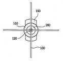
Translated fromKorean도 1은 본 발명의 바람직한 제1 실시예에 따른 혈관 압박 장치를 설명하기 위한 개략적인 측면도이다.1 is a schematic side view for explaining a blood vessel compression device according to a first embodiment of the present invention.
도 2는 도 1에 도시된 혈관 압박 장치를 설명하기 위한 개략적인 정면도이다.FIG. 2 is a schematic front view for explaining the blood vessel compression device shown in FIG. 1.
도 3은 도 1에 도시된 혈관 압박 장치에서 핀이 돌출된 상태를 설명하기 위한 개략적인 측면도이다.FIG. 3 is a schematic side view for explaining a state where the pin protrudes in the blood vessel compression device shown in FIG. 1.
도 4는 도 3에 도시된 혈관 압박 장치를 설명하기 위한 개략적이 정면도이다.FIG. 4 is a schematic front view for explaining the blood vessel compression device shown in FIG. 3.
도 5는 도 3에 도시된 혈관 압박 장치가 인체 조직에 고정된 상태를 설명하기 위한 도면이다.FIG. 5 is a view for explaining a state in which the blood vessel compression device shown in FIG. 3 is fixed to human tissue.
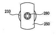
도 6은 본 발명의 바람직한 제2 실시예에 따른 혈관 압박 장치를 설명하기 위한 개략적인 측면도이다.Figure 6 is a schematic side view for explaining the blood vessel compression device according to a second embodiment of the present invention.
도 7은 도 6에 도시된 혈관 압박 장치를 설명하기 위한 개략적인 정면도이다.FIG. 7 is a schematic front view for describing the blood vessel compression device shown in FIG. 6.
도 8은 도 6에 도시된 혈관 압박 장치를 설명하기 위한 개략적인 배면도이다.FIG. 8 is a schematic rear view for explaining the blood vessel compression device shown in FIG. 6.
도 9는 도 6에 도시된 혈관 압박 장치에서 핀과 전극이 돌출된 상태를 설명하기 위한 개략적인 측면도이다.FIG. 9 is a schematic side view for explaining a state in which the pin and the electrode protrude from the blood vessel compression device shown in FIG. 6.
도 10은 도 6에 도시된 혈관 압박 장치를 설명하기 위한 개략적이 정면도이다.FIG. 10 is a schematic front view for explaining the blood vessel compression device shown in FIG. 6.
* 도면의 주요부분에 대한 부호의 설명 *Explanation of symbols on the main parts of the drawings
10 : 인체 조직20 : 혈관10: human tissue 20: blood vessel
110 : 손잡이120 : 침투관110: handle 120: penetration tube
130 : 핀150 : 액추에이터130: pin 150: actuator
160 : 홀더210 : 손잡이160: Holder 210: Handle
220 : 침투관230 : 핀220: penetration tube 230: pin
240 : 전극250 : 액추에이터240: electrode 250: actuator
260 : 홀더270 : 전원부260: holder 270: power supply
280 : 전원 연결부280: power connection
본 발명은 외과적 수술시 사용되는 혈관 압박 장치에 관한 것으로, 보다 상세하게는 외과적 수술시 수술의 편리를 위해 혈관을 압박하여 혈류를 차단하는 혈관 압박 장치에 관한 것이다.The present invention relates to a vascular compression device to be used in surgical operations, and more particularly to a vascular compression device to block blood flow by compressing the blood vessels for the convenience of surgery during surgical operation.
외과적 수술이란 일반적으로 피부나 점막, 기타의 조직을 의료 기계를 사용 하여 자르거나 째거나 조작을 가하여 병을 고치는 일을 말한다. 외과적 수술은 크게 피를 내며 하는 관혈적 수술과 피를 내지 않고 하는 비관혈적 수술이 있다.Surgical surgery usually involves cutting, slitting, or manipulating skin, mucous membranes, or other tissues with a medical device to repair a disease. Surgical operations include large bleeding invasive surgery and non-blood invasive surgery.
관혈적 수술은 배를 가른 상태에서 수술하는 개복 수술 등을 말하며 수술 후 환자의 회복 시간이 오래 걸리고, 후유증이나 합병증의 가능성이 크며 수술 후 통증도 크다. 또한 관혈적 수술을 위해서는 전신 마취를 해야하는 문제점이 있다. 따라서 전신 마취가 필요 없으며, 근육손상, 신경손상, 관절손상, 뼈의 손상이 적고 수술 후 환자의 회복이 빠른 비관혈적 수술이 많이 시행되고 있다.Open surgery refers to open surgery, such as surgery to cover the abdomen, the patient takes a long recovery time after surgery, the likelihood of sequelae or complications are great, and the postoperative pain is large. There is also a problem that requires general anesthesia for invasive surgery. Therefore, there is no need for general anesthesia, and many of the non-invasive operations have been performed to reduce muscle damage, nerve damage, joint damage, bone damage, and quick recovery of the patient after surgery.
상기 비관혈적 수술 중에도 내출혈을 방지하기 위해서나 수술의 효과를 높이기 위해 혈관을 압박함으로써 혈관의 혈류를 차단해야 하는 경우가 있다. 종양의 치료 방법의 하나로 이용되는 종양의 온도를 상승시켜 암세포 조직을 치료하는 발열요법(hyperthermia)이 있다. 상기 발열요법의 경우 암세포 조직의 주위를 흐르는 혈액이 냉각 작용을 하여 충분한 치료 효과를 얻지 못하게 되는 문제점이 발생한다.Even during the non-invasive surgery, blood vessels may be blocked by compressing blood vessels to prevent internal bleeding or to increase the effectiveness of the surgery. One of the methods of treating tumors is hyperthermia, which increases the temperature of tumors and treats cancer cell tissues. In the case of the fever therapy, the blood flowing around the cancer cell tissue has a problem that the cooling effect does not obtain a sufficient therapeutic effect.
상기와 같은 문제점을 해결하기 위한 본 발명의 목적은 비관혈적 수술에서 혈관을 압박하여 혈관의 혈류를 차단하여 치료 효과를 높이기 위한 혈관 압박 장치를 제공하는 데 있다.An object of the present invention for solving the above problems is to provide a vascular compression device for increasing the therapeutic effect by blocking the blood flow of the blood vessel by compressing the blood vessel in non-invasive surgery.
상기 본 발명의 목적을 달성하기 위하여 본 발명은 손잡이와, 일단은 상기 손잡이와 연결되고, 타단은 인체 조직의 내부로 삽입하기 위해 날카롭게 형성되는 침투관과, 상기 침투관의 내부에 이동 가능하도록 배치되고, 상기 침투관이 상기 조직에 삽입된 상태에서 상기 침투관의 타단으로부터 상기 침투관의 삽입 방향 방향에 대하여 측방으로 아크(arc) 형태를 가지도록 돌출되며, 혈액의 흐름을 차단하기 위해 상기 조직의 혈관을 당기거나 눌러 압박하는 탄성 재질의 핀 및 상기 침투관의 길이 방향과 동일한 방향으로 이동 가능하도록 구비되고, 상기 핀을 상기 침투관 내부로 수용하거나 상기 침투관 외부로 돌출시키기 위한 액추에이터를 포함하는 것을 특징으로 하는 혈관 압박 장치를 제공한다.In order to achieve the object of the present invention, the present invention is a handle, one end is connected to the handle, the other end is formed to be sharply inserted to insert into the human tissue, and arranged to be movable inside the penetration tube And the protruding tube has an arc shape laterally from the other end of the penetrating tube in a state in which the penetrating tube is inserted into the tissue and has an arc shape in order to block the flow of blood. It is provided to be movable in the same direction as the longitudinal direction of the pin and the elastic material and the elastic pin to pull or press the blood vessel of the, and includes an actuator for receiving the pin into the inside of the penetrating tube or protrudes out of the penetrating tube Provided is a blood vessel compression device.
상기 혈관 압박 장치는 상기 핀이 상기 혈관을 당기면서 압박하는 경우, 상기 침투관의 외측면을 따라 이동 가능하도록 장착되고, 상기 혈관이 압박된 상태를 유지하도록 고정하기 위해 상기 인체 조직의 표피에 밀착되어 상기 침투관의 외측면에 고정되는 홀더를 더 포함한다. 또한 상기 혈관 압박 장치는 상기 침투관의 내부에 상기 액추에이터의 의해 이동 가능하도록 배치되고, 상기 침투관이 상기 혈관을 압박하는 동안 상기 침투관의 타단으로부터 상기 침투관의 삽입 방향에 대하여 측방으로 아크 형태를 가지도록 상기 핀과 다른 길이만큼 돌출되며, 상기 조직의 병변을 가열하기 위한 전극 및 상기 전극에 고주파 전력을 제공하기 위한 전원부를 더 포함한다.The blood vessel compression device is mounted to be movable along the outer surface of the penetrating tube when the pin is pressed while pulling the blood vessel, and closely adheres to the epidermis of the human tissue to fix the vessel to remain in a compressed state. And a holder fixed to an outer surface of the penetration tube. In addition, the blood vessel compression device is arranged to be movable by the actuator in the inside of the infiltration pipe, the arc shape laterally with respect to the insertion direction of the infiltration pipe from the other end of the infiltration pipe while the infiltration pipe is pressing the blood vessel Protruding to a different length than the pin to have, and further comprises an electrode for heating the lesion of the tissue and a power supply for providing a high frequency power to the electrode.
상기 핀은 니켈 티타늄 재질로 형성된 형상 기억 합금으로 형성되고, 테프론 재질의 절연 물질로 코팅된다.The pin is formed of a shape memory alloy formed of nickel titanium and coated with an insulating material of Teflon.
이와 같이 구성된 본 발명에 따른 혈관 압박 장치는 상기 침투관을 이용하여 비관혈식으로 혈관을 압박할 수 있으므로 혈류의 차단이 가능하다. 따라서 종양 등 의 병변을 온열요법을 이용하여 치료하는 경우 그 효과를 극대화할 수 있다.In the blood vessel compression device according to the present invention configured as described above, the blood vessels can be blocked by non-invasive blood using the infiltration tube, thereby blocking blood flow. Therefore, the treatment of tumors, such as tumors using heat therapy can maximize the effect.
이하, 첨부한 도면을 참조하여 본 발명의 바람직한 실시예들에 따른 혈관 압박 장치에 대해 상세히 설명한다.Hereinafter, with reference to the accompanying drawings will be described in detail a blood vessel compression device according to preferred embodiments of the present invention.
도 1은 본 발명의 바람직한 제1 실시예에 따른 혈관 압박 장치를 설명하기 위한 개략적인 측면도이고, 도 2는 도 1에 도시된 혈관 압박 장치를 설명하기 위한 개략적인 정면도이다.1 is a schematic side view for explaining a blood vessel compression device according to a first embodiment of the present invention, Figure 2 is a schematic front view for explaining the blood vessel compression device shown in FIG.
도 3은 도 1에 도시된 혈관 압박 장치에서 핀이 돌출된 상태를 설명하기 위한 개략적인 측면도이고, 도 4는 도 3에 도시된 혈관 압박 장치를 설명하기 위한 개략적이 정면도이다.FIG. 3 is a schematic side view for explaining a pin protruding state in the blood vessel compression device shown in FIG. 1, and FIG. 4 is a schematic front view for explaining the blood vessel compression device shown in FIG. 3.
또한 도 5는 도 3에 도시된 혈관 압박 장치가 인체 조직에 고정된 상태를 설명하기 위한 도면이다.5 is a view for explaining a state in which the blood vessel compression device shown in Figure 3 is fixed to the human tissue.
도 1 내지 도 5를 참조하면, 혈관 압박 장치(100)는 손잡이(110), 일단은 손잡이(110)와 연결되고 타단은 인체 조직(10)의 내부로 삽입하기 위해 날카롭게 형성되는 침투관(120), 침투관(120)의 내부에 이동 가능하도록 배치되고 침투관(120)이 인체 조직(10)에 삽입된 상태에서 침투관(120)의 타단으로부터 침투관(120)의 삽입 방향 방향에 대하여 측방으로 아크(arc) 형태를 가지도록 돌출되며 혈액의 흐름을 차단하기 위해 조직(10)의 혈관(20)을 당기거나 눌러 압박하는 탄성 재질의 핀(130), 침투관(120)의 길이 방향과 동일한 방향으로 이동 가능하도록 구비되고 핀(130)을 침투관(120) 내부로 수용하거나 침투관(120) 외부로 돌출시키기 위한 액추에이터(150) 및 침투관(120)의 외측면을 따라 이동 가능하도록 장착되고 핀(120) 이 혈관(20)을 당기면서 압박하는 경우, 혈관(20)이 압박된 상태를 유지하도록 고정하기 위해 인체 조직(10)의 표피에 밀착되어 침투관(120)의 외측면에 고정되는 홀더(160)를 포함한다.1 to 5, the blood vessel compression device 100 is connected to the
손잡이(110)는 플라스틱 또는 금속 재질로 형성되며, 손으로 잡기에 편리한 중공의 원통형 구조를 갖는다. 도시되지는 않았지만 손잡이(110)의 일단은 캡에 의해 개방이 가능하도록 형성되는 것이 바람직하다.The
침투관(120)은 서스(sus) 재질로 형성되며, 얇고 긴 관 형태의 구조를 갖는다. 침투관(120)의 일단은 상기 손잡이(120)와 연결된다. 침투관(120)의 타단은 인체 조직(10)의 내부로 삽입하기에 용이하도록 사선 형태로 날카롭게 형성되어 있다. 침투관(120)의 길이는 17.5cm, 25.0cm, 30.0cm 등이 적당하나 이에 국한되지는 않는다. 침투관(120)의 실제적 길이는 의사가 복강경, 피부관통, 또 다른 과정 중 어느 것을 택하느냐 아니냐 뿐만 아니라, 압박할 혈관(20)의 위치, 피부로부터의 거리, 접근 가능성(accessibility)에도 좌우된다. 침투관(120)의 지름은 하기에서 설명할 다수개의 핀(130)을 동시에 수용할 만한 공간을 가지도록 충분히 크게 형성된다.The
침투관(120)의 외측면에 눈금이 형성된다. 침투관(120)의 눈금을 통해 상기 침투관이 상기 인체 조직(10)에 얼마나 삽입되었는지를 확인할 수 있다.A scale is formed on the outer surface of the
침투관(120)의 표면은 절연 물질로 코팅되는 것이 바람직하다. 혈관 압박 장치(100)는 고주파를 이용하여 병변 부위를 가열하기 위한 고주파 치료 장치와 병행해서 사용되는 경우가 많다. 침투관(120)을 절연 물질로 코팅함으로써 인체 조직(10) 내에서 침투관(120)과 고주파 치료 장치의 전극이 서로 통전되는 것을 방지할 수 있다. 상기 절연 물질로는 다양한 물질이 사용될 수 있지만 테프론 재질이 사용되는 것이 바람직하다. 상기 테프론 재질은 절연성, 내마모성 및 내화학성이 뛰어나 장기간 사용이 가능하다.The surface of the
핀(130)은 인체 조직(10) 내의 혈관(20)을 압박하여 혈류를 차단하기 위한 것으로, 침투관(120)의 내부에 침투관(120)을 따라 이동 가능하도록 배치된다. 침투관(120)이 인체 조직(10)에 삽입된 상태에서 도 3에서와 같이 침투관(120)의 타단으로부터 돌출된다. 핀(130)은 침투관(120)의 내부에 위치하는 경우에는 침투관(120)의 모양으로 인해 직선 형태를 가지고, 침투관(120)의 타단으로부터 돌출되는 경우에는 침투관(120)이 인체 조직(10)에 삽입되는 방향에 대하여 측방으로 아크(arc) 형태를 가진다.The
상기와 같이 변화된 형태를 가지기 위해서 핀(130)은 아크 형태를 갖는 형상 기억(shape memory alloy)으로 형성된다. 핀(130)은 아크 형태의 형상 기억 합금으로 침투관(120)의 내부에 위치한 상태에서는 침투관(120)의 내부면이 가이드 역할을 하므로 직선 형태를 유지하게 된다. 그러나 핀(130)이 침투관(120)의 타단으로부터 돌출되면 침투관(120)의 삽입 방향에 대하여 측방으로 원래의 형태인 아크 형태를 회복한다.In order to have the changed shape as described above, the
핀(130)의 재질은 형상 기억 합금을 제조하기 위해 니티놀(nitinol)이라 불리는 니켈-티타늄 합금, 니켈-티타늄-구리 합금, 니켈-티타늄-코발트 합금 및 구리-아연-알루미늄 합금이 사용된다. 형상 기억 합금은 금속 고상 상태에서의 상 변태의 일종인 마텐자이트(martensite) 결정변태와 동일한 현상을 이용한 것으로, 열탄성 마텐자이트 변태를 나타내는 합금은 예외 없이 형상기억 특성을 나타낸다. 또한 형상 기억 합금은 금속 고상 상태에서의 상변태 중 오스테나이트(austenite) 결정 변태와 동일한 현상을 이용할 수도 있다.The material of the
마텐자이트 변태의 경우 형상 기억 합금은 합금의 종류에 따라 각각 196 (Ni-Ti 합금), 294 (Ni-Ti-Co 합금), 68~98 (Ni-Ti-Cu 합금)의 허용 강도(kgf/mmㅂ)를 가지고, 각각 7845~9800 (Ni-Ti 합금), 9800~13730 (Ni-Ti-Co 합금), 0~4900 (Ni-Ti-Cu 합금)의 탄성율(kgf/mmㅂ)을 갖는다.In the case of martensitic transformation, the shape memory alloy has a permissible strength (kgf) of 196 (Ni-Ti alloy), 294 (Ni-Ti-Co alloy), and 68 to 98 (Ni-Ti-Cu alloy), respectively, depending on the alloy type. / mm ㅂ) and elastic modulus (kgf / mm ㅂ) of 7845 ~ 9800 (Ni-Ti alloy), 9800 ~ 13730 (Ni-Ti-Co alloy), and 0 ~ 4900 (Ni-Ti-Cu alloy), respectively. Have
오스테나이트 변태의 경우 형상 기억 합금은 합금의 종류에 따라 각각 390~785 (Ni-Ti 합금), 490~980 (Ni-Ti-Co 합금), 390~785 (Ni-Ti-Cu 합금)의 허용 강도(kgf/mmㅂ)를 가지고, 17650~21575 (Ni-Ti 합금), 25500~28440 (Ni-Ti-Co 합금), 19615~27460 (Ni-Ti-Cu 합금)의 탄성율(kgf/mmㅂ)을 갖는다.In the case of austenite transformation, the shape memory alloy is allowed in the range of 390 ~ 785 (Ni-Ti alloy), 490 ~ 980 (Ni-Ti-Co alloy), and 390 ~ 785 (Ni-Ti-Cu alloy), respectively, depending on the alloy type. Elasticity (kgf / mm ㅂ) of 17650 ~ 21575 (Ni-Ti alloy), 25500 ~ 28440 (Ni-Ti-Co alloy), 19615 ~ 27460 (Ni-Ti-Cu alloy) with strength (kgf / mm ㅂ) Has
핀(130)의 돌출 길이는 3 cm 정도 돌출되는 것이 바람직하고, 또한 핀(130)은 혈관(20)의 혈류를 차단하기 위해 가해지는 힘을 견딜 수 있는 충분한 강도를 지녀야 한다. 핀(130)의 개수는 경우에 따라 다양하게 형성될 수 있지만, 4개 정도가 구비되는 것이 바람직하다.It is preferable that the protruding length of the
핀(130)은 침투관(120)과 마찬가지로 절연 물질로 코팅된다. 혈관 압박 장치(100)는 고주파를 이용하여 병변 부위를 가열하기 위한 고주파 치료 장치와 병행해서 사용되는 경우가 많다. 핀(130)을 절연 물질로 코팅함으로써 인체 조직(10) 내에서 핀(130)과 상기 고주파 치료 장치의 전극 사이의 통전을 방지할 수 있다. 상기 절연 물질로는 다양한 물질이 사용될 수 있지만 테프론 재질이 사용되는 것이 바람직하다.The
침투관(120)의 타단으로부터 돌출된 핀(130)은 인체 조직(10) 내의 혈관(20)을 압박하여 혈류를 차단한다. 핀(130)이 상기 혈관(20)을 압박하는 방법으로는 우선 손잡이(110)를 침투관(120) 삽입 방향을 따라 밀어 핀(130)이 상기 혈관(20)을 누르게 하는 방법이 있다. 이 경우, 상기 도면에서와 같이 핀(130)이 침투관(120)을 중심으로 방사상으로 서로 동일한 간격만큼 이격되도록 배치된다.The
또한 도 5에서와 같이 손잡이(110)를 침투관(120) 삽입 방향과 반대 방향을 따라 잡아당겨 핀(130)이 상기 혈관(20)을 누르게 하는 방법이 있다. 이 경우, 핀(130)은 한 개가 구비되거나, 다수 개가 구비되는 경우 어느 한 방향으로 몰려 구비되는 것이 바람직하다. 핀(130)이 방사상으로 서로 동일 간격 이격되도록 배치된 경우, 손잡이(110)를 침투관(120) 삽입 방향과 반대 방향으로 잡아당길 때 아크 형태를 가지는 핀(130)이 혈관(20) 주위의 조직뿐만 아니라 혈관(20)과 이격된 부위의 조직에 손상을 입히게 된다. 따라서 핀(130)을 한 개 구비하거나 또는 다수개를 한 방향으로 몰리도록 구비함으로써 혈관(20)과 이격된 건강한 조직의 손상을 최소화할 수 있다.In addition, as shown in FIG. 5, the
인체 내부의 조직(10)과 혈관(20)의 위치 등을 고려하여 상기 두 가지 방법 중 어느 하나를 선택되어 사용하는 것이 바람직하다.In consideration of the location of the
액추에이터(150)는 중공의 원통형 구조를 갖는 손잡이(110)에서 개방된 일단을 통하여 삽입되고, 침투관(120)의 삽입 방향을 따라 직선 왕복 운동이 가능하도 록 구비된다. 즉 액추에이터(150)는 손잡이(110)의 내부에서 피스톤 운동을 하게 된다.The
액추에이터(150)는 손잡이(110) 내부에 삽입되는 부분과 손잡이(110) 외부로 돌출된 부분으로 나뉜다. 액추에이터(150)는 손잡이(110) 내부의 공간에 의해 이동 범위가 한정된다.액추에이터(150) 중 손잡이(110) 외부로 돌출된 부분은 시술자의 손으로 잡기 편리하도록 손잡이(110)의 반지름보다 더 큰 장반경을 갖는 타원형 구조를 갖는다. 따라서 액추에이터(150)의 피스톤 운동을 용이하게 한다.The
액추에이터(150)는 핀(130)과 연결된 상태이므로 직선 왕복 운동에 따라 핀(130)을 침투관(120) 내부로 수용하거나 침투관(120) 외부로 돌출시킨다. 따라서 손잡이(110) 내부 공간의 크기를 조정하여 핀(130)의 돌출 길이를 조절할 수 있다.Since the
홀더(160)는 침투관(120)의 외측면을 따라 이동 가능하도록 장착된다. 홀더(160)는 핀(130)이 혈관(20)을 당기면서 압박하는 경우, 인체 조직(10)의 표피에 밀착되어 침투관(120)의 외측면에 고정되어 혈관(20)이 압박된 상태를 유지한다.The
홀더(160)에 의해 혈관(20)이 압박된 상태를 유지할 뿐만 아니라 혈관 압박 장치(100) 자체도 고정이 되므로, 시술자가 혈관 압박 장치(100)를 고정하던 손이 자유롭게 된다. 따라서 시술자는 두 손을 이용하여 시술할 수 있어 보다 정확하게 시술할 수 있고, 또한 다른 작업을 할 수도 있다.Since the
상기 혈관 압박 장치(100)를 이용하여 환자의 조직(10)을 절개하지 않고 혈관(20)을 압박하여 혈류를 차단할 수 있다By using the blood vessel compression device 100, blood pressure may be blocked by cutting the
도 6은 본 발명의 바람직한 제2 실시예에 따른 혈관 압박 장치를 설명하기 위한 개략적인 측면도이고, 도 7은 도 6에 도시된 혈관 압박 장치를 설명하기 위한 개략적인 정면도이며, 도 8은 도 6에 도시된 혈관 압박 장치를 설명하기 위한 개략적인 배면도이다.FIG. 6 is a schematic side view for explaining a blood vessel compression device according to a second preferred embodiment of the present invention, FIG. 7 is a schematic front view for explaining the blood vessel compression device shown in FIG. 6, and FIG. 8 is FIG. 6. It is a schematic back view for demonstrating the vascular compression device shown in FIG.
도 9는 도 6에 도시된 혈관 압박 장치에서 핀과 전극이 돌출된 상태를 설명하기 위한 개략적인 측면도이고, 도 10은 도 6에 도시된 혈관 압박 장치를 설명하기 위한 개략적이 정면도이다.FIG. 9 is a schematic side view for explaining the protruding state of the pin and the electrode in the blood vessel compression device shown in FIG. 6, and FIG. 10 is a schematic front view for explaining the blood vessel compression device shown in FIG. 6.
도 6 내지 도 10을 참조하면, 혈관 압박 장치(200)는 손잡이(210), 일단은 손잡이(210)와 연결되고 타단은 인체 조직(10)의 내부로 삽입하기 위해 날카롭게 형성되는 침투관(220), 침투관(220)의 내부에 이동 가능하도록 배치되고 침투관(220)이 인체 조직(10)에 삽입된 상태에서 침투관(220)의 타단으로부터 침투관(220)의 삽입 방향 방향에 대하여 측방으로 아크(arc) 형태를 가지도록 돌출되며 혈액의 흐름을 차단하기 위해 조직(10)의 혈관(20)을 당기거나 눌러 압박하는 탄성 재질의 핀(230), 침투관(220)의 내부에 핀(230)과 같이 이동 가능하도록 배치되고, 침투관(220)의 타단으로부터 침투관(220)의 삽입 방향에 대하여 측방으로 아크 형태를 가지도록 돌출되며, 핀(230)이 혈관(20)을 압박하는 동안 조직(10)의 병변을 가열하기 위한 전극(240), 침투관(220)의 길이 방향과 동일한 방향으로 이동 가능하도록 구비되고 핀(230) 및 전극(240)을 침투관(220) 내부로 수용하거나 침투관(220) 외부로 돌출시키기 위한 액추에이터(250), 침투관(220)의 외측면을 따라 이동 가능하도록 장착되고 핀(120)이 혈관(20)을 당기면서 압박하는 경우, 혈관(20)이 압박된 상태를 유지하도록 고정하기 위해 인체 조직(10)의 표피에 밀착되어 침투관(120)의 외측면에 고정되는 홀더(160) 및 전극(240)에 고주파 전력을 제공하기 위한 전원부(270)를 포함한다.6 to 10, the blood vessel compression device 200 is connected to the
상기 도면을 참조하면, 제2 실시예에 의한 혈관 압박 장치(200)는 전극(230), 액추에이터(250) 및 전원부(270)를 제외하고는 상술한 제1 실시예와 동일하다.Referring to the drawings, the blood vessel compression device 200 according to the second embodiment is the same as the first embodiment described above except for the
따라서 전극(230), 액추에이터(250) 및 전원부(270)를 제외한 나머지 부분에 대한 설명은 중복되므로 생략한다.Therefore, descriptions of the remaining parts except for the
핀(230)은 제1 실시예와 동일하게 절연 물질로 코팅되지만, 그 이유는 후술되는 전극(240)과의 통전을 방지하기 위함이고, 상기 절연 물질로는 제1 실시예와 동일하게 테프론 재질이 사용되는 것이 바람직하다.The
전극(230)은 인체 조직(10)의 병변 부위를 가열하기 위한 것으로, 침투관(220)의 내부에 핀(230)과 같이 또는 각각 이동 가능하도록 배치되고, 침투관(220)이 인체 조직(10)에 삽입된 상태에서 침투관(220)의 타단으로부터 돌출된다. 전극(230)은 핀(230)과 마찬가지로 침투관(220)의 내부에 위치하는 경우에는 직선 형태를 가지고, 침투관(220)의 타단으로부터 돌출되는 경우에는 침투관(220)의 삽입 방향에 대하여 측방으로 아크(arc) 형태를 가진다.The
상기와 같이 변화된 형태를 가지기 위해서는 전극(240)은 핀(230)과 동일하게 아크 형태를 갖는 형상 기억 합금으로 형성된다. 전극(240)은 아크 형태의 형상 기억 합금으로 침투관(220)의 내부에 위치한 상태에서는 침투관(220)의 내부면이 가이드 역할을 하므로 직선 형태를 유지하게 된다. 그러나 전극(240)이 침투관(220)의 타단으로부터 돌출되면 침투관(220)의 삽입 방향에 대하여 측방으로 원래의 형태인 아크 형태를 회복한다. 전극(240)의 재질은 형상 기억 합금을 제조하기 위해 니켈-티타늄 합금, 니켈-티타늄-구리 합금, 니켈-티타늄-코발트 합금 및 구리-아연-알루미늄 합금이 사용된다. 전극(240)의 구체적인 재질이나 성질에 대한 설명은 제1 실시예에서의 핀(120)과 동일하므로 생략한다.In order to have the changed shape as described above, the
전극(240)의 돌출 길이는 병변의 위치나 크기에 따라 달라질수 있으나 보통은 핀(230)의 돌출 길이보다 긴 것이 바람직하다. 전극(240)의 개수는 다양하게 형성될 수 있지만, 2개 정도가 구비되는 것이 바람직하다.The protruding length of the
상기 도면에서 전극(240)은 아크 형태를 가지는 형상 기억 합금인 것으로 도시되었지만, 일반적인 직선 형태를 가지는 금속 재질일 수도 있다.Although the
또한, 상기 도면에서는 도시되지 않았지만, 전극(240)의 말단에는 온도를 측정할 수 있는 센서가 구비될 수도 있다. 상기 센서를 구비하여 전극(240)에 의해 가열되는 병변 조직의 가열 온도를 확인할 수 있다.
상기 전극(240)은 병변 부위를 직접 가열하므로, 환자의 안전을 보장할 수 있는 전극(240)의 전류값 및 임피던스 값이 설정되어야 한다. 예를 들면, 상기 전류값은 약 140mA 이하의 범위이며, 임피던스 값은 25 내지 1000 ohms 사이의 범위인 것이 바람직하다. 상기와 같은 범위의 전류값 및 임피던스 값 조건에서 상기 전극(240) 주변의 온도 분포는 상기 전극(240)으로부터 반경 약 3cm 이내의 범위에서 약 60 내지 125도로 유지될 수 있다.In addition, although not shown in the drawing, a sensor capable of measuring temperature may be provided at the end of the
Since the
전원부(270)는 전극(240)에서 발열이 이루어져 병변을 가열할 수 있도록 전원을 공급한다. 전원부(270)의 전원으로는 주로 고주파가 사용된다. 상기 고주파는 약 200 내지 1200kHz의 주파수 범위를 가지며, 약 200 내지 300V의 진폭 크기를 갖는다.The
액추에이터(250)는 제1 실시예와 유사하나, 손잡이(210)의 외측으로 돌출된 액추에이터(250)의 단부에 전극(240)과 연결되며 전원부(270)와 연결되기 위한 전원 연결부(280)가 구비된다. 전원 연결부(280)는 전원부(280)로부터 연장되는 케이 블에 의해 연결된다.
핀(230)과 전극(240)이 침투관(220)으로부터 같이 돌출되는 경우에는 액추에이터(250)는 일체로 구성된다. 그러나 핀(230)과 전극(240)이 침투관(220)으로부터 각각 돌출될 수 있는 경우에는 액추에이터(250)는 핀(230)과 연결되며 핀(230)을 침투관(220)으로부터 돌출시키거나 침투관(220) 내부로 수용하는 부분과, 전극(240)과 연결되며 전극(240)을 침투관(220)으로부터 돌출시키거나 침투관(220) 내부로 수용하는 부분으로 구성된다. 물론 이 경우에 전원 연결부(280)는 전극(240)과 연결되는 액추에이터(250)에 연결된다.When the
상기의 혈관 압박 장치(200)는 혈관(20)을 압박하여 혈류를 차단할 수 있는 핀(230)과 조직(10)의 병변 부위를 가열할 수 있는 전극(240)을 동시에 구비한다. 따라서 핀(230)을 이용하여 혈관(20)의 혈류를 차단한 상태에서 전극(240)을 이용하여 조직(10)의 병변 부위를 보다 넓은 범위에 보다 높은 온도로 가열할 수 있다.The blood vessel compression device 200 includes a
종양과 같은 조직(10)의 병변 부위의 온도를 상승시키면 암세포조직을 치료하는데 많은 도움이 된다. 암세포조직에 대한 발열요법의 세포효과로는 첫째, 세포막(또는 핵막)의 투과성 또는 유동성의 변화, 둘째 소화효소의 배출을 유발하는 세포질의 리소좀분열, 셋째 세포호흡작용과 DNA 또는 RNA의 합성에 영향을 미치는 단백질 열 손상, 넷째로 면역체계의 자극가능성 등이 제안되고 있다.Increasing the temperature of the lesion site of the
전극(240)에서 발열되는 과정을 살펴보면, 고주파 장애로 인해 고주파 교류가 전극(240)에서 세포조직으로 흐른다. 이온이 교류의 방향의 변화를 따르려 하기 때문에, 이온의 애지테이션(agitation)이 전극(240)의 말단 세포조직 영역에서 일 어난다. 이는 마찰로 인한 열을 발생하여, 전극(240)이 아닌 전극(240) 부근의 조직(10)이 열 발생의 주원인이 된다. 조직(10)의 열 생성은 전류가 조직(10)에 의해 제공된 전기적 저항을 통과하면서 생성된다. 이때, 저항이 클수록 더 많은 열이 생성된다.Looking at the process of the heat generated from the
전류가 전극(240)의 말단에서부터 방사 상으로 뻗어나가므로, 전류밀도는 전극(240)의 말단에서 가장 높게 나타나고, 전극(240)의 말단에서 멀어질수록 점점 더 낮아진다. 따라서, 가열효과는 전극(240)에서 가장 크게 나타나고, 전극(240)에서 멀어질수록 감소하게된다.Since the current extends radially from the end of the
상술한 바와 같이, 본 발명의 바람직한 실시예에 따른 혈관 압박 장치는 침투관과 핀을 이용하여 환자의 조직을 절개하지 않고 혈관을 압박하여 혈류를 차단할 수 있다. 또한 전극을 이용하여 조직의 병변을 가열하여 치료할 수 있다. 상기 혈관의 혈류가 차단되므로 조직의 병변을 가열할 때 가열 효과를 높일 수 있고, 조직을 절개하지 않으므로 치료 후 회복이 빠르다.As described above, the blood vessel compression device according to the preferred embodiment of the present invention may block blood flow by compressing blood vessels without cutting the tissue of the patient using the infiltration tube and the pin. The electrode can also be used to treat tissue lesions by heating. Since the blood flow of the blood vessels is blocked, the heating effect can be increased when heating the tissue lesion, and since the tissue is not incised, recovery after treatment is quick.
상기에서는 본 발명의 바람직한 실시예를 참조하여 설명하였지만, 해당 기술 분야의 숙련된 당업자는 하기의 특허 청구 범위에 기재된 본 발명의 사상 및 영역으로부터 벗어나지 않는 범위 내에서 본 발명을 다양하게 수정 및 변경시킬 수 있음을 이해할 수 있을 것이다.While the foregoing has been described with reference to preferred embodiments of the present invention, those skilled in the art will be able to variously modify and change the present invention without departing from the spirit and scope of the invention as set forth in the claims below. It will be appreciated.
Claims (7)
Translated fromKoreanPriority Applications (2)
| Application Number | Priority Date | Filing Date | Title |
|---|---|---|---|
| KR1020030091129AKR100624161B1 (en) | 2003-12-15 | 2003-12-15 | Blood vessel compression device |
| PCT/KR2004/003275WO2005055837A1 (en) | 2003-12-15 | 2004-12-14 | Apparatus for pressing a blood vessel |
Applications Claiming Priority (1)
| Application Number | Priority Date | Filing Date | Title |
|---|---|---|---|
| KR1020030091129AKR100624161B1 (en) | 2003-12-15 | 2003-12-15 | Blood vessel compression device |
Publications (2)
| Publication Number | Publication Date |
|---|---|
| KR20050059503A KR20050059503A (en) | 2005-06-21 |
| KR100624161B1true KR100624161B1 (en) | 2006-09-18 |
Family
ID=34675749
Family Applications (1)
| Application Number | Title | Priority Date | Filing Date |
|---|---|---|---|
| KR1020030091129AExpired - Fee RelatedKR100624161B1 (en) | 2003-12-15 | 2003-12-15 | Blood vessel compression device |
Country Status (2)
| Country | Link |
|---|---|
| KR (1) | KR100624161B1 (en) |
| WO (1) | WO2005055837A1 (en) |
Families Citing this family (1)
| Publication number | Priority date | Publication date | Assignee | Title |
|---|---|---|---|---|
| EP4294288A4 (en)* | 2021-02-17 | 2024-08-07 | Dreamedic Ltd. | VESSEL COMPRESSION SYSTEMS |
Family Cites Families (2)
| Publication number | Priority date | Publication date | Assignee | Title |
|---|---|---|---|---|
| EP0740533A4 (en)* | 1994-01-18 | 1998-01-14 | Endovascular Inc | Apparatus and method for venous ligation |
| US20020087151A1 (en)* | 2000-12-29 | 2002-07-04 | Afx, Inc. | Tissue ablation apparatus with a sliding ablation instrument and method |
- 2003
- 2003-12-15KRKR1020030091129Apatent/KR100624161B1/ennot_activeExpired - Fee Related
- 2004
- 2004-12-14WOPCT/KR2004/003275patent/WO2005055837A1/enactiveApplication Filing
Also Published As
| Publication number | Publication date |
|---|---|
| KR20050059503A (en) | 2005-06-21 |
| WO2005055837A1 (en) | 2005-06-23 |
Similar Documents
| Publication | Publication Date | Title |
|---|---|---|
| JP4431637B2 (en) | Apparatus and method for tissue surface treatment | |
| KR101248959B1 (en) | Electrode device having flexible tube for high frequency thermotherapy | |
| EP3744280B1 (en) | Electrosurgical instrument | |
| US9138289B2 (en) | Electrode sheath for electrosurgical device | |
| EP0918490B1 (en) | Instrument for interrupting conduction paths within the heart | |
| US6616654B2 (en) | Polypectomy device and method | |
| EP1768596B1 (en) | Radiation applicator for radiating tissue | |
| US8753335B2 (en) | Therapeutic energy delivery device with rotational mechanism | |
| US7044947B2 (en) | Polypectomy device and method | |
| US20110295249A1 (en) | Fluid-Assisted Electrosurgical Devices, and Methods of Manufacture Thereof | |
| JPH10503959A (en) | Multi-electrode ablation device | |
| US20080312650A1 (en) | Thermal Ablation of Biological Tissue | |
| CN106572884A (en) | Systems and methods for spherical ablations | |
| JP2009273888A (en) | Electrode for high frequency electric surgical instrument which coagulates and necroses biotissue | |
| WO2015100451A1 (en) | Applying electric field treatment to parts of the body | |
| AU2013327705B2 (en) | Selectively deformable ablation device | |
| KR100624161B1 (en) | Blood vessel compression device | |
| EP1416870A1 (en) | Polypectomy device and method | |
| WO2024061659A1 (en) | Electrosurgical instruments | |
| EP4590221A1 (en) | Electrosurgical instrument and electrosurgical apparatus | |
| HK1002098B (en) | Multiple electrode ablation apparatus |
Legal Events
| Date | Code | Title | Description |
|---|---|---|---|
| A201 | Request for examination | ||
| PA0109 | Patent application | St.27 status event code:A-0-1-A10-A12-nap-PA0109 | |
| PA0201 | Request for examination | St.27 status event code:A-1-2-D10-D11-exm-PA0201 | |
| PG1501 | Laying open of application | St.27 status event code:A-1-1-Q10-Q12-nap-PG1501 | |
| D13-X000 | Search requested | St.27 status event code:A-1-2-D10-D13-srh-X000 | |
| D14-X000 | Search report completed | St.27 status event code:A-1-2-D10-D14-srh-X000 | |
| E902 | Notification of reason for refusal | ||
| PE0902 | Notice of grounds for rejection | St.27 status event code:A-1-2-D10-D21-exm-PE0902 | |
| T11-X000 | Administrative time limit extension requested | St.27 status event code:U-3-3-T10-T11-oth-X000 | |
| T11-X000 | Administrative time limit extension requested | St.27 status event code:U-3-3-T10-T11-oth-X000 | |
| T11-X000 | Administrative time limit extension requested | St.27 status event code:U-3-3-T10-T11-oth-X000 | |
| T11-X000 | Administrative time limit extension requested | St.27 status event code:U-3-3-T10-T11-oth-X000 | |
| P11-X000 | Amendment of application requested | St.27 status event code:A-2-2-P10-P11-nap-X000 | |
| P13-X000 | Application amended | St.27 status event code:A-2-2-P10-P13-nap-X000 | |
| E701 | Decision to grant or registration of patent right | ||
| PE0701 | Decision of registration | St.27 status event code:A-1-2-D10-D22-exm-PE0701 | |
| GRNT | Written decision to grant | ||
| PR0701 | Registration of establishment | St.27 status event code:A-2-4-F10-F11-exm-PR0701 | |
| PR1002 | Payment of registration fee | St.27 status event code:A-2-2-U10-U11-oth-PR1002 Fee payment year number:1 | |
| PG1601 | Publication of registration | St.27 status event code:A-4-4-Q10-Q13-nap-PG1601 | |
| PR1001 | Payment of annual fee | St.27 status event code:A-4-4-U10-U11-oth-PR1001 Fee payment year number:4 | |
| PR1001 | Payment of annual fee | St.27 status event code:A-4-4-U10-U11-oth-PR1001 Fee payment year number:5 | |
| FPAY | Annual fee payment | Payment date:20110906 Year of fee payment:6 | |
| PR1001 | Payment of annual fee | St.27 status event code:A-4-4-U10-U11-oth-PR1001 Fee payment year number:6 | |
| R18-X000 | Changes to party contact information recorded | St.27 status event code:A-5-5-R10-R18-oth-X000 | |
| LAPS | Lapse due to unpaid annual fee | ||
| PC1903 | Unpaid annual fee | St.27 status event code:A-4-4-U10-U13-oth-PC1903 Not in force date:20120908 Payment event data comment text:Termination Category : DEFAULT_OF_REGISTRATION_FEE | |
| PC1903 | Unpaid annual fee | St.27 status event code:N-4-6-H10-H13-oth-PC1903 Ip right cessation event data comment text:Termination Category : DEFAULT_OF_REGISTRATION_FEE Not in force date:20120908 | |
| R18-X000 | Changes to party contact information recorded | St.27 status event code:A-5-5-R10-R18-oth-X000 |