KR100623494B1 - Winder - Google Patents
WinderDownload PDFInfo
- Publication number
- KR100623494B1 KR100623494B1KR1020050047299AKR20050047299AKR100623494B1KR 100623494 B1KR100623494 B1KR 100623494B1KR 1020050047299 AKR1020050047299 AKR 1020050047299AKR 20050047299 AKR20050047299 AKR 20050047299AKR 100623494 B1KR100623494 B1KR 100623494B1
- Authority
- KR
- South Korea
- Prior art keywords
- winding
- rotary
- power generating
- disc
- guide
- Prior art date
- Legal status (The legal status is an assumption and is not a legal conclusion. Google has not performed a legal analysis and makes no representation as to the accuracy of the status listed.)
- Expired - Fee Related
Links
Images


Classifications
- B—PERFORMING OPERATIONS; TRANSPORTING
- B65—CONVEYING; PACKING; STORING; HANDLING THIN OR FILAMENTARY MATERIAL
- B65H—HANDLING THIN OR FILAMENTARY MATERIAL, e.g. SHEETS, WEBS, CABLES
- B65H75/00—Storing webs, tapes, or filamentary material, e.g. on reels
- B65H75/02—Cores, formers, supports, or holders for coiled, wound, or folded material, e.g. reels, spindles, bobbins, cop tubes, cans, mandrels or chucks
- B65H75/18—Constructional details
- B65H75/24—Constructional details adjustable in configuration, e.g. expansible
- B—PERFORMING OPERATIONS; TRANSPORTING
- B65—CONVEYING; PACKING; STORING; HANDLING THIN OR FILAMENTARY MATERIAL
- B65H—HANDLING THIN OR FILAMENTARY MATERIAL, e.g. SHEETS, WEBS, CABLES
- B65H18/00—Winding webs
- B65H18/08—Web-winding mechanisms
- B—PERFORMING OPERATIONS; TRANSPORTING
- B65—CONVEYING; PACKING; STORING; HANDLING THIN OR FILAMENTARY MATERIAL
- B65H—HANDLING THIN OR FILAMENTARY MATERIAL, e.g. SHEETS, WEBS, CABLES
- B65H2701/00—Handled material; Storage means
- B65H2701/10—Handled articles or webs
- B65H2701/18—Form of handled article or web
- B65H2701/184—Wound packages
- B65H2701/1844—Parts concerned
- B65H2701/18442—Core
Landscapes
- Storing, Repeated Paying-Out, And Re-Storing Of Elongated Articles (AREA)
Abstract
Translated fromKoreanDescription
Translated fromKorean도 1은 본 발명에 따른 권취기를 보여주는 전체 개략 사시도.1 is an overall schematic perspective view showing a winder according to the present invention.
도 2는 도 1의 권취기의 권취부의 개략 부분확대 사시도.FIG. 2 is a schematic partially enlarged perspective view of a winding unit of the winding machine of FIG. 1; FIG.
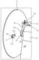
도 3은 본 발명에 따른 권취기의 소재 권취 작업시 권취부와 가동레버부의 작동상태를 보여주는 개략 측면도.Figure 3 is a schematic side view showing the operating state of the winding unit and the movable lever portion during the winding work of the winding machine according to the present invention.
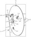
도 4는 본 발명에 따른 권취기의 소재롤의 분리 작업시 권취부와 가동레버부의 작동상태를 보여주는 개략 측면도.Figure 4 is a schematic side view showing the operating state of the winding portion and the movable lever portion during the separation work of the roll material of the winder according to the present invention.
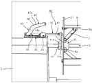
도 5는 소재 권취 작업시 권취부의 개략 부분확대 배면 사시도.5 is a schematic partially enlarged rear perspective view of a winding unit during a work of winding a material;
도 6은 소재롤의 분리 작업시 권취부의 개략 부분확대 배면 사시도.6 is a schematic partially enlarged rear perspective view of the winding-up part during the separation work of the material roll;
도 7은 소재 권취 작업시 권취부의 개략 부분확대 전면 사시도.7 is a schematic partially enlarged front perspective view of a winding unit during a work of winding a material;
도 8은 소재롤의 분리 작업시 권취부의 개략 부분확대 전면 사시도로서 회전날개의 일부분을 단면처리하여 슬라이딩 안내부의 전측부분을 보여주는 도면.Figure 8 is a schematic enlarged front perspective view of the winding portion during the separation operation of the raw material roll showing the front portion of the sliding guide by sectional processing of a portion of the rotary blade.
<도면의 주요부분에 대한 부호의 설명><Description of the symbols for the main parts of the drawings>
1: 베이스 1a: 이동롤러1:
1b: 높이조절 받침대 2: 동력발생부1b: height adjustment base 2: power generating unit
3: 회전축 4: 고정편3: shaft 4: fixed piece
4a, 6a: 대응부분(또는 돌출부분) 5: 지지대4a, 6a: counterpart (or protrusion) 5: support
6: 회전날개 6aa, 44a: 관통홀6: rotor blade 6aa, 44a: through hole
7: 권취부 8: 제어패널부7: Winding section 8: Control panel section
8a: 제어버튼 8b: 액정표시부8a:
9: 케이스 10: 감속부9: case 10: reduction unit
11: 권취해제부 12: 본체부11: unwinding part 12: main body part
20: 원판부 21a, 22a: 관통홀20:
21b: 가이드홈 21: 원판21b: guide groove 21: disc
22b: 링형홈 22: 안내편22b: Ring Groove 22: Guide Piece
30: 슬라이딩 안내부 31a: 헤드부분30: sliding
31b: 나사부 31: 볼트부재31b: thread 31: bolt member
32: 너트부재 33: 환형링32: nut member 33: annular ring
40: 가동레버부 41a: 원호부40:
41: 제1 연결부재 42: 제2 연결부재41: first connecting member 42: second connecting member
43: 레버부 44: 지지브라켓43: lever 44: support bracket
45: 패스너 46: 지지링크45: fastener 46: support link
47: 작동레버 47a: 손잡이부분47:
48: 피복재48: cladding
본 발명은 권취기에 관한 것으로, 특히 일반비닐, 폐비닐, 끈이나 로프 형태의 긴 줄 등을 권취하는데 모두 적용 가능하며, 무엇보다도 농업분야에서 발생되는 폐비닐을 권취기를 이용해 롤형태로 조밀하게 권취할 수 있게 하고, 아울러 그 권취된 폐비닐롤을 권취기의 권취부로부터 편리하게 분리시킬 수 있도록 하는 권취기에 관한 것이다.The present invention relates to a winding machine, and in particular, can be applied to all windings, such as general vinyl, waste vinyl, string or rope form, and above all, dense winding of the waste vinyl generated in the agricultural field in the form of a roll using a winder The present invention relates to a winder, which enables a convenient and separate separation of the wound waste vinyl roll from the winder of the winder.
일반적으로, 권취 가능 소재중에는 비닐이 있는데, 농업용 비닐의 종류로는 지온조절 또는 잡초의 성장억제 등을 위한 멀칭(Mulching)용 비닐, 농작물 재배나 축사 등을 위한 비닐하우스용 비닐 등이 있다.Generally, there are vinyls among the coilable materials. Examples of agricultural vinyl include vinyl for mulching for controlling temperature or inhibiting weed growth, and vinyl for vinyl house for crop cultivation or barn.
매년, 많은 양의 비닐이 농촌에서 사용되어지고 있으며, 사용후 발생하는 폐비닐은 수거되는 양에 비해 재활용되는 양이 상대적으로 적어 폐비닐의 야적량은 계속해서 증가하고 있는 추세이다.Every year, a large amount of vinyl is used in rural areas, and waste vinyl generated after use is relatively less recycled compared to the amount collected, and the amount of waste vinyl continues to increase.
또한, 종래에는 작업자가 전적으로 수작업에 의존해 불규칙한 형태로 폐비닐을 회수하였기 때문에 폐비닐과 인접한 폐비닐 간에 빈 공간이 생겨 회수된 전체 폐비닐의 부피가 상대적으로 커질 수밖에 없었으며, 그를 운반하는데도 매우 불편하였다.In addition, in the prior art, since the operator recovered the waste vinyl in an irregular form depending solely on manual labor, empty space was created between the waste vinyl and the adjacent waste vinyl, which caused the volume of the entire waste vinyl to be recovered to be relatively large, which is very inconvenient to transport. It was.
한편, 상기 멀칭용 비닐은 흙, 자갈 등과 직접적으로 접촉되어 사용되는 것이기 때문에 추후 사용되고 난 폐비닐을 수거할 때 흙, 자갈, 나무조각 등이 인접한 폐비닐에 의해 둘러싸여 그대로 재활용을 위한 야적장에 쌓이게 되는 문제점이 있었다.On the other hand, since the mulching vinyl is used in direct contact with soil, gravel and the like, when the used vinyl is collected later, soil, gravel, wood chips, etc. are surrounded by adjacent waste vinyl and are stacked in a yard for recycling as it is. There was a problem.
게다가, 폐비닐과 함께 흙, 자갈, 나무조각 등의 불순물이 재활용 공정 상의 분쇄기에 투입되었을 때 분쇄기의 분쇄날을 손상시키거나, 또는 분쇄날 사이에 끼어 종종 분쇄기의 고장을 초래하였다.In addition, impurities such as soil, gravel, wood chips, etc., together with waste vinyl, damaged the grinding blades of the grinder when they were put into the grinder in the recycling process, or were caught between the grinding blades and often caused the failure of the grinder.
이에, 본 발명은 전술한 문제점을 해소하기 위해 안출된 것으로, 그 목적은 흙, 자갈, 나무조각 등의 불순물이 폐비닐과 함께 수거되는 것을 미연에 차단할 수 있도록 하는 권취기를 제공하는 것이다.Accordingly, the present invention has been made to solve the above-described problems, the object of the present invention is to provide a winding machine that can block the collection of impurities such as soil, gravel, wood chips and the like with the waste vinyl in advance.
본 발명의 다른 목적은 권취부를 이용하여 폐비닐을 롤형태로 편리하게 권취할 수 있도록 하는 권취기를 제공하는 것이다.It is another object of the present invention to provide a winding machine which can conveniently wind up waste vinyl in a roll form using a winding portion.
본 발명의 또 다른 목적은 롤형태로 감긴 폐비닐을 권취부로부터 편리하게 분리시킬 수 있도록 하는 권취기를 제공하는 것이다.It is still another object of the present invention to provide a winder which allows the waste vinyl wound in the form of a roll to be conveniently separated from the winding portion.
전술한 목적을 달성하기 위해, 본 발명에 따른 권취기는 베이스와; 이 베이스 상에 일정높이로 장착되는 동력발생부와; 이 동력발생부의 출력단과 결합되는 회전축과, 이 회전축의 적어도 두 개소에 구비되어 그 회전축과 일체로 회전되는 고정편과, 이 각 고정편의 적어도 두 개소에 내측단이 각각 힌지연결되는 지지대와, 동일축선상에 배치된 적어도 두 지지대의 외측단에 각각 힌지연결되어 상기 회전축과 일체로 회전되며, 권취 가능 소재를 권취할 시 그 회전축의 반경방향 외측으로 확장된 상태로 유지 가능하고 그 권취된 소재를 분리시킬 시 그 회전축의 반경방향 내측으로 축소 가능한 회전날개로 구성되는 권취부와; 상기 동력발생부와 전기적으로 연결되어 그 동력발생부를 제어 가능하게 하는 제어패널부를 포함하는 것을 특징으로 한다.In order to achieve the above object, the winder according to the present invention and the base; A power generating unit mounted on the base at a predetermined height; A rotating shaft coupled to the output end of the power generating portion, a fixed piece provided at at least two locations of the rotating shaft and integrally rotated with the rotating shaft, and a support having an inner end hinged to at least two of the fixed pieces, respectively. It is hinged to each of the outer ends of at least two supports arranged on the axis and rotated integrally with the rotary shaft, and when winding the rollable material, it is possible to maintain the expanded state radially outward of the rotary shaft and A winding portion composed of a rotary blade that can be reduced inwardly in the radial direction of the rotary shaft when being separated; And a control panel unit electrically connected to the power generator to control the power generator.
이하, 본 발명의 실시예를 도 1 내지 도 8을 참조하여 설명하면 다음과 같다.Hereinafter, an embodiment of the present invention will be described with reference to FIGS. 1 to 8.
도 1은 본 발명에 따른 권취기를 보여주는 전체 개략 사시도이고, 도 2는 도 1의 권취기의 권취부의 개략 부분확대 사시도이다.1 is an overall schematic perspective view showing a winder according to the present invention, Figure 2 is a schematic partially enlarged perspective view of the winding of the winder of FIG.
본 발명에 따른 권취기는 도 1과 도 2에 도시된 바와 같이, 베이스(1)와; 이 베이스 상에 일정높이로 장착되는 동력발생부(2)와; 이 동력발생부의 출력단과 결합되는 회전축(3)과, 이 회전축의 적어도 두 개소에 구비되어 그 회전축과 일체로 회전되는 고정편(4)과, 이 각 고정편의 적어도 두 개소에 내측단이 각각 힌지연결되는 지지대(5)와, 동일축선상에 배치된 적어도 두 지지대의 외측단에 각각 힌지연결되어 상기 회전축(3)과 일체로 회전되며, 권취 가능 소재(예를 들면, 일반비닐, 폐비닐, 각종 끈 또는 줄 등)를 권취할 시 그 회전축의 반경방향 외측으로 확장된 상태로 유지 가능하고 그 권취된 소재를 분리시킬 시 그 회전축의 반경방향 내측으로 축소 가능한 회전날개(6)로 구성되는 권취부(7)와; 상기 동력발생부(2)와 전기적으로 연결되어 그 동력발생부를 제어 가능하게 하는 제어패널부(8)를 포함하는 구조로 이루어져 있다.The winding machine according to the present invention, as shown in Figures 1 and 2, and the base (1); A
여기에서, 상기 베이스(1)의 저면에는 적어도 3개의 이동롤러(1a), 그리고 그 베이스에는 적어도 3개의 높이조절 받침대(1b)가 더 구비되며, 그에 따라 작업자는 권취기를 사용할 시 상기 높이조절 받침대(1b)를 이용하여 권취기를 바닥면에 평행하게 유지시킬 수 있다(도 1 참조).Here, at least three moving rollers (1a), and at least three height adjustment pedestal (1b) is further provided on the bottom of the base (1), whereby the operator when using the winding machine (1b) can be used to keep the winder parallel to the floor (see FIG. 1).
상기 동력발생부(2)는 모터 또는 트럭이나 경운기 등의 동력원(또는 내연기관)으로 이루어질 수 있으며, 그 동력발생부는 적어도 부분적으로 케이스(9)에 의해 둘러싸이는 것이 바람직하다(도 1과 도 2 참조).The
상기 케이스(9)의 외벽에는 청소용 브러쉬(도시되지 않음)를 착탈 가능하게 수용할 수 있도록 홀더(도시되지 않음)가 구비될 수 있다. 상기 홀더는 적어도 일방이 개구된 포켓형 수용부, 고리형 수용부, 상기 브러쉬와 홀더에 짝으로 구비되는 암수형태의 벨크로테이프 등 다양하게 구비될 수 있다. 그에 따라, 작업자는 권취 대상물(예를 들면, 폐비닐)의 권취시 그 권취 대상물에 달라붙은 흙 등과 같은 이물질을 상기 브러쉬를 이용하여 편리하게 제거할 수 있게 된다. 그밖에도, 작업자는 에어콤프레셔를 이용하여 압축공기를 분사해 상기 권취 대상물에 달라붙은 이물질을 제거할 수 있다.A holder (not shown) may be provided on an outer wall of the
상기 동력발생부(2)는 감기는 소재의 인장력에 따라 회전속도가 조절되는 것(예를 들면, 그 동력발생부에 부하(load)가 크게 걸릴 때 저속으로 회전하고 부하가 작게 걸릴 때 상대적으로 고속으로 회전하는 것)으로서 그 동력발생부의 구동축이 상기 권취부(7)의 회전축(3)과 결합되는 것이거나, 또는 감속부(10)를 매개로 하여 상기 권취부(7)의 회전축(3)에 구비된 구동기어(도시되지 않음)와 결합되는 타입으로 이루어질 수 있다. 상기 감속부(10)는 기어박스 또는 벨트-풀리 기구로 이루어지는 것이 바람직하다.The
상기 각 고정편(4)과 지지대(5)의 내측단, 그리고 각 지지대(5)의 외측단과 회전날개(6) 간의 힌지연결구조는 각 지지대(5)의 내,외측단이 해당 고정편(4) 또 는 회전날개(6)의 대응부분(4a 또는 6a)(또는 관통홀이 형성된 돌출부분)에 패스너(예를 들면, 볼트와 너트, 또는 잠금핀)를 매개로 하여 회전 가능하게 고정된 것으로 이해하면 된다.The hinge connection structure between the inner end of each
또한, 상기 각 고정편(4)은 상기 회전축(3)에 개별적으로 끼워져 고정되는 것뿐만 아니라, 미리 소정 파이프(도시되지 않음)의 외주면 상에 각각 끼워져 고정된 후, 그 파이프를 통해 상기 회전축(3)에 일괄적으로 끼워져 패스너 등을 통해 고정될 수도 있다.In addition, the
상기 각 지지대(5)의 내측단과 회전날개(6)의 대응부분(6a)중 한쪽에는 돌기부가 형성된 판스프링(도시되지 않음), 그리고 다른 한쪽에는 그 판스프링의 돌기부에 상응하는 대응홈(도시되지 않음)이 더 추가될 수 있으며, 이러한 판스프링 돌기부-대응홈 구조는 작업자가 적은 힘을 들이고서도 상기 각 회전날개(6)를 용이하게 권취 또는 분리시의 상태로 전환시킬 수 있게 한다.One of the inner end of each
한편, 다른 실시예로 본 발명의 권취기에는 상기 권취부(7)의 각 회전날개(6)를 회전축(3)에 대해 반경방향으로 단번에 확장 또는 축소 가능하게 하는 권취해제부(11)가 더 구비될 수 있다(도 1과 도 2 참조).On the other hand, in another embodiment, the winding machine of the present invention further includes a take-up
상기 권취해제부(11)는 각 회전날개(6)를 회전축(3)에 대해 반경방향으로 확장 또는 축소 가능하게 안내하는 원판부(20)와, 이 원판부를 회전축(3)의 축선을 따라 전후로 이동 가능하게 하고 그 원판부(20)를 통해 각 회전날개(6)를 권취시 또는 분리시의 상태로 가변 가능하게 하는 가동레버부(40)로 이루어져 있다(도 1과 도 4 참조).The winding
상기 원판부(20)는 중앙에 관통홀(21a)이 형성되고 축선을 중심으로 반경방향으로 적어도 두 개소에 가이드홈(21b)이 형성된 원판(21)과, 상기 각 회전날개(6)의 후측단을 상기 원판(21)의 해당 가이드홈(21b)을 따라 반경방향으로 이동 가능하게 하는 슬라이딩 안내부(30)와, 상기 원판(21)과 함께 회전축(3)의 축선을 따라 이동 가능하도록 중앙에 관통홀(22a)이 형성됨과 아울러 그 원판(21)의 후측 중앙부분에 일체로 고정되고 외주변에 링형홈(22b)이 형성된 안내편(22)으로 이루어져 있다(도 4, 도 6 및 도 8 참조).The
상기 슬라이딩 안내부(30)는 헤드부분(31a)이 해당 가이드홈(21b)의 외측에 배치되는 볼트부재(31)와, 이 볼트부재의 나사부(31b)가 관통 가능하도록 해당 회전날개(6)의 내측에 구비되는 관통홀(6aa)을 갖는 돌출부분(6a)과, 이 돌출부분의 양측 상기 볼트부재(31)의 나사부(31b)와 결합되는 너트부재(32)로 이루어져 있다(도 6 및 도 8 참조).The sliding
상기 볼트부재(31)의 헤드부분(31a)의 내측에는 그 볼트부재의 헤드부분(31a)과 원판(21) 사이에 마찰력을 줄일 수 있도록 환형링(33)이 더 구비되는 것이 바람직하다(도 6 참조).It is preferable that an
상기 가동레버부(40)는 상기 원판부(20)의 안내편(22)의 링형홈(22b)에 상응하여 일측단에 원호부(41a)가 구비된 제1 연결부재(41)와, 이 제1 연결부재의 타측단과 결합되는 제2 연결부재(42)와, 이 제2 연결부재를 전후로 이동 가능하게 하는 레버부(43)로 이루어져 있다(도 3과 도 4 참조).The
상기 레버부(43)는 제2 연결부재(42)의 외측단을 안내할 수 있도록 전측부분 에 안내용 관통구(44a)가 구비되고 패스너(45)를 매개로 하여 권취기의 케이스(9) 상부에 착탈 가능하게 배치되는 지지브라켓(44)과, 양측의 각 일단부가 상기 제2 연결부재(42)의 후측단과 힌지연결되는 한 쌍의 지지링크(46)와, 상기 지지브라켓(44)의 후측부에 하측단이 힌지연결되고 그 하측단으로부터 일정거리의 하부부분에 상기 한 쌍의 지지링크(46)의 타단부가 각각 힌지연결되는 작동레버(47)로 이루어져 있다(도 3과 도 4 참조). 상기 작동레버(47)의 손잡이부분(47a)에는 절연성 재질의 피복재(48)가 구비되는 것이 바람직하다.The
한편, 또 다른 실시예로 상기 권취해제부(11)를 대신하여 상기 권취부(7)의 적어도 한 고정편(4)에는 각 지지대(5)의 선회를 차단하는 착탈 가능한 형태의 패스너(도시되지 않음)가 더 구비될 수 있다.Meanwhile, in another embodiment, at least one fixing
다른 한편, 상기 각 회전날개(6)를 회전축(3)에 대해 일정 곡률반경을 갖도록 형성하면 폐비닐을 롤형태로 권취하는데 용이하고, 또한 그 회전날개의 전체개수를 줄이는 것도 가능하게 한다.On the other hand, when the
상기 제어패널부(8)에는 동력발생부(2)를 제어하는 제어버튼(8a)이 구비되며, 일부분에는 권취기의 회전수, 회전속도 등을 표시해주는 액정표시부(8b)가 더 구비될 수 있다(도 1과 도 2 참조).The
전술한 바와 같이 구성된 본 발명에 따른 권취기의 조립과정 및 그 작용을 설명하면 다음과 같다.Referring to the assembly process and its operation of the winding machine according to the present invention configured as described above are as follows.
아래의 권취기의 조립과정은 하나의 바람직한 조립예를 설명하는 것으로서, 작업자의 편의에 따라 일부의 순서를 달리하여 조립하는 것도 가능하다.The assembling process of the winding machine below describes one preferred assembly example, and it is also possible to assemble some parts in different order according to the convenience of the operator.
우선, 편의상 회전축(3), 고정편(4), 지지대(5) 및 회전날개(6)를 포함하는 권취부(7); 베이스(1), 동력발생부(2), 감속부(10), 케이스(9) 및 제어패널부(8)를 포함하는 본체부(12); 원판부(20) 및 가동레버부(40)를 포함하는 권취해제부(11)를 각각 조립한다(도 1과 도 2 참조).First, a winding
여기에서, 상기 권취부(7)의 경우, 먼저 회전축(3)의 양측에 그 회전축과 일체를 이루도록 고정편(4)을 끼워 고정시킨다.Here, in the case of the said winding | winding
그런 다음, 상기 각 고정편(4)의 대응부분(4a)(또는 돌출부분)에 패스너(볼트와 너트, 또는 잠금핀)를 이용하여 각 지지대(5)의 내측단을 회전 가능하게 연결한다.Then, the inner end of each
그런 다음, 동일축선상에 배치된 적어도 두 지지대(5)의 외측단에 회전날개(6)를 위치시켜 전술한 바와 같은 패스너를 이용하여 해당 지지대(5)의 외측단과 회전날개(6)의 대응부분(6a)을 회전 가능하게 연결하면 된다.Then, the
한편, 상기 본체부(12)의 경우, 먼저 베이스(1) 상에 모터(전기적 감속 가능 모터 포함) 또는 경운기 등의 동력원으로 이루어진 동력발생부(2)를 위치시켜 나사 등과 같은 패스너(도시되지 않음)를 이용하여 고정한다.On the other hand, in the case of the
그런 다음, 상기 동력발생부(2)의 출력단에 기어박스 또는 벨트-풀리 기구로 이루어진 감속부(10)를 위치시켜 패스너를 이용하여 고정한다.Then, at the output end of the
다른 한편, 상기 권취해제부(11)의 경우, 먼저 원판부(20)의 원판(21)과 그 원판에 일체로 고정된 안내편(22)을 상기 권취부(7)의 회전축(3)의 후측단을 통해 끼운다(도 4와 도 6 참조).On the other hand, in the case of the unwinding
그런 다음, 상기 원판(21)의 각 가이드홈(21b)에 해당 회전날개(6)의 후측단을 정렬시킨 후, 슬라이딩 안내부(30)의 일부분을 이루는 볼트부재(31), 환형링(33) 및 너트부재(32)를 이용하여 상기 원판(21)의 가이드홈(21b)을 통해 그 원판(21)과 회전날개(6)측 돌출부분(6a)을 상호 연결한다(도 6과 도 8 참조).Then, after aligning the rear end of the
그런 다음, 상기 원판부(20)를 포함하는 권취부(7)의 회전축(3)을 본체부(12)의 동력발생부(2)의 출력단, 또는 감속부(10)에 위치시켜 패스너를 이용하여 고정한 후, 상기 본체부(12)를 케이스(9)로 덮은 다음, 그 케이스를 베이스(1)에 고정시킨다(도 1과 도 2 참조).Then, the
그런 다음, 가동레버부(40)의 제1 연결부재(41)와 제2 연결부재(42)의 대응단부를 상호 고정한 상태에서 상기 제1 연결부재(41)의 원호부(41a)를 상기 원판부(20)의 안내편(22)의 링형홈(22b)에 끼운다. 그런 다음, 상기 제1 연결부재(41)의 원호부(41a)와 안내편(22)의 링형홈(22b)이 결합된 상태에서, 상기 제2 연결부재(42)의 외측단을 본체부(12)의 케이스(9) 상측 지지브라켓(44)의 안내용 관통구(44a)를 통해 끼운 후, 상기 지지브라켓(44)을 다수 개의 패스너(45)를 이용하여 케이스(9)에 고정한다(도 4와 도 6 참조).Then, the
그런 다음, 상기 제2 연결부재(42)의 외측단의 양측에 한 쌍의 지지링크(46)의 일단부를 힌지연결하고, 작동레버(47)의 하단부를 상기 지지브라켓(44)의 후측부에 힌지연결한 후, 상기 한 쌍의 지지링크(46)의 타단부를 상기 작동레버(47)의 하부부분에 힌지연결하면 된다(도 3과 도 4 참조).Then, one end of the pair of support links 46 is hinged to both sides of the outer end of the second connecting
한편, 본 발명에 따른 권취기의 각 회전날개(6)를 회전축(3)에 대해 반경방 향 외측으로 확장된 상태 또는 내측으로 축소된 상태로 유지시키는 방식에는 각 지지대(5)의 내측단과 해당 회전날개(6)의 대응부분 사이의 마찰력을 이용하고 각 회전날개를 개별적으로 조작하는 방식과, 상기 각 지지대(5)의 내측단과 해당 회전날개(6)의 대응부분 사이에 판스프링 돌기부-대응홈 구조를 개재시키고 각 회전날개(6)를 개별적으로 조작하는 방식과, 각 회전날개(6)를 다함께 동작시키는 권취해제부(11)를 장착하고 각 회전날개(6)를 단번에 제어하는 방식 등으로 이루어질 수 있다.On the other hand, the inner edge of each support (5) and the corresponding method for maintaining each of the
다음은 전술한 바와 같이 조립 완료된 권취기의 작용에 대한 설명으로서, 전술한 두 방식의 작용은 당업자에게 자명할 것으로 사료되어 편의상 생략하기로 하고, 상기 권취해제부를 이용하여 각 회전날개를 단번에 권취시의 확장상태 또는 분리시의 축소상태로 제어 가능하게 하는 방식에 대하여 자세히 설명하고자 한다.The following is a description of the operation of the winder is assembled as described above, the operation of the above two methods will be apparent to those skilled in the art will be omitted for convenience, when winding each rotary blade at a time by using the winding release portion. It will be described in detail how to enable the control in the expanded state of the state or the collapsed state of separation.
권취 가능 소재(예를 들면, 폐비닐)를 권취시키기 위해 권취부의 각 회전날개를 확장상태로 유지시키고자 하는 경우, 가동레버부(40)의 작동레버(47)를 후방으로 젖히면 그 작동레버를 통해 한 쌍의 지지링크(46)가 후방으로 당겨져 그 지지링크와 연결된 제2 연결부재(42)가 후측으로 이동되게 된다(도 3, 도 5 및 도 7 참조).In order to keep each rotary blade of the winding part in an expanded state in order to wind up the winding-able material (for example, waste vinyl), the operating
그러면, 상기 제2 연결부재(42)와 연결된 제1 연결부재(41)의 원호부(41a)가 원판(21)의 후측 안내편(22)의 링형홈(22b)을 통해 상기 원판(21)을 회전축(3)의 축선을 따라 후방으로 끌어당기게 된다(도 3 참조).Then, the
그러면, 상기 원판(21)의 각 가이드홈(21b)에 슬라이딩 안내부(30)를 매개로 하여 연결된 회전날개(6)가 상기 원판(21)과 함께 후방으로 이동되게 되며, 그 결과 각 회전날개(6)는 상기 가동레버부(40)에 의해 확장상태 또는 권취상태로 유지되게 된다(도 7 참조).Then, the
이때, 상기 각 회전날개(6)는 회전축(3)의 적어도 두 개소에 고정된 고정편(4)과 해당 회전날개(6) 사이에 회전 가능하게 배치된 지지대(5)를 통해 회전되게 되고, 아울러 상기 각 회전날개(6)의 후측단은 상기 원판(21)의 가이드홈(21b)을 통해 반경방향 외측으로 안내되게 된다.At this time, each of the
그에 따라, 작업자는 상기 회전날개(6)의 외주변에 권취 가능 소재, 예를 들면 필름형태의 폐비닐을 일정권수로 감아 자체적으로 고정시킨 후, 제어패널부(8)를 통해 동력발생부(2)를 가동시켜 일정량의 폐비닐을 적당한 크기의 롤형태로 조밀하게 감을 수 있게 된다(도 1 참조).Accordingly, the operator winds the woundable material, for example, film-type vinyl, around the
한편, 감겨진 폐비닐을 권취부의 회전날개(6)로부터 분리시키기 위해 회전날개를 축소상태로 유지시키고자 하는 경우, 먼저 제어패널부(8)를 통해 동력발생부(2)에 인가되는 전원을 오프시킨 상태에서 상기 가동레버부(40)의 작동레버(47)를 전방으로 젖히면 그 작동레버를 통해 한 쌍의 지지링크(46)가 전방으로 밀려져 그 지지링크와 연결된 제2 연결부재(42)가 전측으로 이동되게 된다(도 2와 도 4 참조).On the other hand, in order to keep the rotary blades in a reduced state in order to separate the wound vinyl from the
그러면, 상기 제2 연결부재(42)와 연결된 제1 연결부재(41)의 원호부(41a)가 원판(21)의 후측 안내편(22)의 링형홈(22b)을 통해 상기 원판(21)을 회전축(3)의 축선을 따라 전방으로 밀게 된다(도 4와 도 6 참조).Then, the
그러면, 상기 원판(21)의 각 가이드홈(21b)에 슬라이딩 안내부(30)를 매개로 하여 연결된 각 회전날개(6)가 상기 원판(21)과 함께 전방으로 이동되게 되며, 그 결과 상기 각 회전날개(6)는 상기 가동레버부(40)에 의해 상기 회전축(3)의 반경방향 내측으로 축소되는 권취 해제상태로 유지되게 된다(도 2, 도 4 및 도 8 참조).Then, each
이때, 상기 각 회전날개(6)는 회전축(3)의 적어도 두 개소에 고정된 고정편(4)과 해당 회전날개(6) 사이에 회전 가능하게 배치된 지지대(5)를 통해 회전되게 되고, 아울러 상기 각 회전날개(6)의 후측단은 상기 원판(21)의 가이드홈(21b)을 통해 반경방향 내측으로 안내되게 된다.At this time, each of the
그러면, 작업자는 롤형태로 감긴 폐비닐을 상기 권취부(7)의 회전날개(6)로부터 용이하게 분리시킬 수 있게 된다.Then, the worker can easily separate the waste vinyl wound in the form of a roll from the
전술한 바와 같이, 본 발명은 권취 가능소재, 예를 들면 폐비닐의 수거시 권취기의 권취부에 흙, 자갈, 나무조각 등의 불순물이 폐비닐과 함께 감기는 것을 미연에 차단할 수 있게 한다.As described above, the present invention makes it possible to block the winding of the waste material together with the waste vinyl, such as soil, gravel, wood chips, etc., on the winding portion of the winder during collection of the waste vinyl.
또한, 본 발명은 권취부를 이용하여 폐비닐을 롤형태로 편리하게 감을 수 있게 한다.In addition, the present invention makes it possible to conveniently wind up the waste vinyl in the form of a roll by using a winding portion.
나아가, 본 발명은 롤형태로 감긴 폐비닐을 권취부로부터 편리하게 분리시킬 수 있게 한다.Furthermore, the present invention makes it possible to conveniently separate the waste vinyl wound in the form of a roll from the winding portion.
아울러, 본 발명의 권취기에 의해 권취된 폐비닐은 롤형태로 수거되기 때문에 일정장소에 적재되거나 다른 곳으로 운반하고자 할 때 매우 편리하다.In addition, since the waste vinyl wound by the winding machine of the present invention is collected in the form of a roll, it is very convenient when it is to be placed in a certain place or to be transported to another place.
Claims (10)
Translated fromKoreanPriority Applications (1)
| Application Number | Priority Date | Filing Date | Title |
|---|---|---|---|
| KR1020050047299AKR100623494B1 (en) | 2005-06-02 | 2005-06-02 | Winder |
Applications Claiming Priority (1)
| Application Number | Priority Date | Filing Date | Title |
|---|---|---|---|
| KR1020050047299AKR100623494B1 (en) | 2005-06-02 | 2005-06-02 | Winder |
Publications (1)
| Publication Number | Publication Date |
|---|---|
| KR100623494B1true KR100623494B1 (en) | 2006-09-13 |
Family
ID=37624790
Family Applications (1)
| Application Number | Title | Priority Date | Filing Date |
|---|---|---|---|
| KR1020050047299AExpired - Fee RelatedKR100623494B1 (en) | 2005-06-02 | 2005-06-02 | Winder |
Country Status (1)
| Country | Link |
|---|---|
| KR (1) | KR100623494B1 (en) |
Cited By (7)
| Publication number | Priority date | Publication date | Assignee | Title |
|---|---|---|---|---|
| CN103449216A (en)* | 2013-07-25 | 2013-12-18 | 桐城市福润包装材料有限公司 | Numerically-controlled film cutting machine |
| KR200475449Y1 (en)* | 2013-01-03 | 2014-12-03 | (주)위드 | file suppling apparatus and attery Cell side tape Automatic Adhesion Machine the same |
| CN110803559A (en)* | 2019-10-23 | 2020-02-18 | 朱青松 | Coiled material winding mechanism |
| CN111137739A (en)* | 2018-11-02 | 2020-05-12 | 江苏帝诚线缆有限公司 | Cable winding and unwinding frame |
| KR20200077662A (en)* | 2018-12-20 | 2020-07-01 | 주식회사 불스 | Vinyl collecting device |
| CN112499398A (en)* | 2020-12-11 | 2021-03-16 | 大连奥特马工业有限公司 | Winding mechanism of splitting machine |
| CN115497694A (en)* | 2022-10-28 | 2022-12-20 | 重庆泰山电缆有限公司 | Film covering device, film covering system and film covering method after wrapping cable water blocking tape |
- 2005
- 2005-06-02KRKR1020050047299Apatent/KR100623494B1/ennot_activeExpired - Fee Related
Cited By (9)
| Publication number | Priority date | Publication date | Assignee | Title |
|---|---|---|---|---|
| KR200475449Y1 (en)* | 2013-01-03 | 2014-12-03 | (주)위드 | file suppling apparatus and attery Cell side tape Automatic Adhesion Machine the same |
| CN103449216A (en)* | 2013-07-25 | 2013-12-18 | 桐城市福润包装材料有限公司 | Numerically-controlled film cutting machine |
| CN111137739A (en)* | 2018-11-02 | 2020-05-12 | 江苏帝诚线缆有限公司 | Cable winding and unwinding frame |
| CN111137739B (en)* | 2018-11-02 | 2023-12-08 | 江苏帝诚线缆有限公司 | Cable winding and unwinding frame |
| KR20200077662A (en)* | 2018-12-20 | 2020-07-01 | 주식회사 불스 | Vinyl collecting device |
| KR102151245B1 (en) | 2018-12-20 | 2020-09-03 | 주식회사 불스 | Vinyl collecting device |
| CN110803559A (en)* | 2019-10-23 | 2020-02-18 | 朱青松 | Coiled material winding mechanism |
| CN112499398A (en)* | 2020-12-11 | 2021-03-16 | 大连奥特马工业有限公司 | Winding mechanism of splitting machine |
| CN115497694A (en)* | 2022-10-28 | 2022-12-20 | 重庆泰山电缆有限公司 | Film covering device, film covering system and film covering method after wrapping cable water blocking tape |
Similar Documents
| Publication | Publication Date | Title |
|---|---|---|
| US8434563B2 (en) | Device for cultivating soil or brushing debris | |
| US7309834B1 (en) | Extendible and retractable extension cord apparatus | |
| KR100623494B1 (en) | Winder | |
| AU2021200640B2 (en) | High-efficiency lawn maintenance tool | |
| US9750180B2 (en) | Powered landscaping system | |
| CN102438797B (en) | Scroll saw | |
| JP6786771B2 (en) | Rotary blades for mowers and mowers using them | |
| MXPA04010959A (en) | Auto-feed/rewind electric cord reel. | |
| CN111432624B (en) | Trimmer head with improved wire release feature | |
| CN108575261B (en) | Greening lawn trimming equipment based on gyroscope automatic leveling technology | |
| JP3218516U (en) | Electric tool connection adapter for winding device and winding device using the same | |
| CN215011655U (en) | Mower with centrifugal paying-off function | |
| CN108566814B (en) | Remote-control automatic green lawn trimming equipment | |
| JP2001148950A (en) | Winding apparatus for polyvinyl chloride sheet | |
| CN114190157A (en) | Lawn trimming device for landscape garden management | |
| CN208446091U (en) | An easy-to-use lawnmower | |
| CN107278494A (en) | Grass-mowing machine | |
| CN213595638U (en) | Wire harness winding device | |
| CN114027019B (en) | Be used for portable lawn mower of municipal garden engineering | |
| US6371401B1 (en) | Apparatus for removing a floor covering | |
| KR200317688Y1 (en) | Apparatus of winding waste vinyl | |
| KR200337891Y1 (en) | The roll system an evil vinyl of a use adherence a cultivator | |
| JP2020184962A (en) | Root hair removal device | |
| CN222328435U (en) | Slitting tool mounting shaft and slitting device | |
| JPH0530599Y2 (en) |
Legal Events
| Date | Code | Title | Description |
|---|---|---|---|
| A201 | Request for examination | ||
| PA0109 | Patent application | St.27 status event code:A-0-1-A10-A12-nap-PA0109 | |
| PA0201 | Request for examination | St.27 status event code:A-1-2-D10-D11-exm-PA0201 | |
| P11-X000 | Amendment of application requested | St.27 status event code:A-2-2-P10-P11-nap-X000 | |
| P13-X000 | Application amended | St.27 status event code:A-2-2-P10-P13-nap-X000 | |
| R15-X000 | Change to inventor requested | St.27 status event code:A-3-3-R10-R15-oth-X000 | |
| R16-X000 | Change to inventor recorded | St.27 status event code:A-3-3-R10-R16-oth-X000 | |
| E701 | Decision to grant or registration of patent right | ||
| PE0701 | Decision of registration | St.27 status event code:A-1-2-D10-D22-exm-PE0701 | |
| GRNT | Written decision to grant | ||
| PR0701 | Registration of establishment | St.27 status event code:A-2-4-F10-F11-exm-PR0701 | |
| PR1002 | Payment of registration fee | St.27 status event code:A-2-2-U10-U11-oth-PR1002 Fee payment year number:1 | |
| PG1601 | Publication of registration | St.27 status event code:A-4-4-Q10-Q13-nap-PG1601 | |
| R18-X000 | Changes to party contact information recorded | St.27 status event code:A-5-5-R10-R18-oth-X000 | |
| R18-X000 | Changes to party contact information recorded | St.27 status event code:A-5-5-R10-R18-oth-X000 | |
| R18-X000 | Changes to party contact information recorded | St.27 status event code:A-5-5-R10-R18-oth-X000 | |
| R18-X000 | Changes to party contact information recorded | St.27 status event code:A-5-5-R10-R18-oth-X000 | |
| PR1001 | Payment of annual fee | St.27 status event code:A-4-4-U10-U11-oth-PR1001 Fee payment year number:4 | |
| PN2301 | Change of applicant | St.27 status event code:A-5-5-R10-R13-asn-PN2301 St.27 status event code:A-5-5-R10-R11-asn-PN2301 | |
| PR1001 | Payment of annual fee | St.27 status event code:A-4-4-U10-U11-oth-PR1001 Fee payment year number:5 | |
| PR1001 | Payment of annual fee | St.27 status event code:A-4-4-U10-U11-oth-PR1001 Fee payment year number:6 | |
| S14-X000 | Exclusive voluntary license recorded | St.27 status event code:A-4-4-S10-S14-lic-X000 | |
| R18-X000 | Changes to party contact information recorded | St.27 status event code:A-5-5-R10-R18-oth-X000 | |
| PN2301 | Change of applicant | St.27 status event code:A-5-5-R10-R13-asn-PN2301 St.27 status event code:A-5-5-R10-R11-asn-PN2301 | |
| PR1001 | Payment of annual fee | St.27 status event code:A-4-4-U10-U11-oth-PR1001 Fee payment year number:7 | |
| R18-X000 | Changes to party contact information recorded | St.27 status event code:A-5-5-R10-R18-oth-X000 | |
| FPAY | Annual fee payment | Payment date:20130725 Year of fee payment:8 | |
| PR1001 | Payment of annual fee | St.27 status event code:A-4-4-U10-U11-oth-PR1001 Fee payment year number:8 | |
| S16-X000 | Recordation of exclusive voluntary license cancelled | St.27 status event code:A-4-4-S10-S16-lic-X000 | |
| S14-X000 | Exclusive voluntary license recorded | St.27 status event code:A-4-4-S10-S14-lic-X000 | |
| S20-X000 | Security interest recorded | St.27 status event code:A-4-4-S10-S20-lic-X000 | |
| PN2301 | Change of applicant | St.27 status event code:A-5-5-R10-R11-asn-PN2301 | |
| PN2301 | Change of applicant | St.27 status event code:A-5-5-R10-R14-asn-PN2301 | |
| FPAY | Annual fee payment | Payment date:20140616 Year of fee payment:9 | |
| PR1001 | Payment of annual fee | St.27 status event code:A-4-4-U10-U11-oth-PR1001 Fee payment year number:9 | |
| P14-X000 | Amendment of ip right document requested | St.27 status event code:A-5-5-P10-P14-nap-X000 | |
| P16-X000 | Ip right document amended | St.27 status event code:A-5-5-P10-P16-nap-X000 | |
| Q16-X000 | A copy of ip right certificate issued | St.27 status event code:A-4-4-Q10-Q16-nap-X000 | |
| R18-X000 | Changes to party contact information recorded | St.27 status event code:A-5-5-R10-R18-oth-X000 | |
| FPAY | Annual fee payment | Payment date:20150907 Year of fee payment:10 | |
| PR1001 | Payment of annual fee | St.27 status event code:A-4-4-U10-U11-oth-PR1001 Fee payment year number:10 | |
| FPAY | Annual fee payment | Payment date:20160906 Year of fee payment:11 | |
| PR1001 | Payment of annual fee | St.27 status event code:A-4-4-U10-U11-oth-PR1001 Fee payment year number:11 | |
| PN2301 | Change of applicant | St.27 status event code:A-5-5-R10-R13-asn-PN2301 St.27 status event code:A-5-5-R10-R11-asn-PN2301 | |
| P22-X000 | Classification modified | St.27 status event code:A-4-4-P10-P22-nap-X000 | |
| S20-X000 | Security interest recorded | St.27 status event code:A-4-4-S10-S20-lic-X000 | |
| FPAY | Annual fee payment | Payment date:20180222 Year of fee payment:12 | |
| PR1001 | Payment of annual fee | St.27 status event code:A-4-4-U10-U11-oth-PR1001 Fee payment year number:12 | |
| R18-X000 | Changes to party contact information recorded | St.27 status event code:A-5-5-R10-R18-oth-X000 | |
| PC1903 | Unpaid annual fee | St.27 status event code:A-4-4-U10-U13-oth-PC1903 Not in force date:20180907 Payment event data comment text:Termination Category : DEFAULT_OF_REGISTRATION_FEE | |
| K11-X000 | Ip right revival requested | St.27 status event code:A-6-4-K10-K11-oth-X000 | |
| PC1903 | Unpaid annual fee | St.27 status event code:N-4-6-H10-H13-oth-PC1903 Ip right cessation event data comment text:Termination Category : DEFAULT_OF_REGISTRATION_FEE Not in force date:20180907 | |
| PR0401 | Registration of restoration | St.27 status event code:A-6-4-K10-K13-oth-PR0401 | |
| PR1001 | Payment of annual fee | St.27 status event code:A-4-4-U10-U11-oth-PR1001 Fee payment year number:13 | |
| FPAY | Annual fee payment | Payment date:20190906 Year of fee payment:14 | |
| PR1001 | Payment of annual fee | St.27 status event code:A-4-4-U10-U11-oth-PR1001 Fee payment year number:14 | |
| PR1001 | Payment of annual fee | St.27 status event code:A-4-4-U10-U11-oth-PR1001 Fee payment year number:15 | |
| PC1903 | Unpaid annual fee | St.27 status event code:A-4-4-U10-U13-oth-PC1903 Not in force date:20210907 Payment event data comment text:Termination Category : DEFAULT_OF_REGISTRATION_FEE | |
| PC1903 | Unpaid annual fee | St.27 status event code:N-4-6-H10-H13-oth-PC1903 Ip right cessation event data comment text:Termination Category : DEFAULT_OF_REGISTRATION_FEE Not in force date:20210907 | |
| P22-X000 | Classification modified | St.27 status event code:A-4-4-P10-P22-nap-X000 |