Movatterモバイル変換


[0]ホーム

URL:


KR100620889B1 - Code Acquisition Technique Using Approximate Maximum Similarity Ratio - Google Patents

Code Acquisition Technique Using Approximate Maximum Similarity Ratio
Download PDF

Info

Publication number
KR100620889B1
KR100620889B1KR1020040059450AKR20040059450AKR100620889B1KR 100620889 B1KR100620889 B1KR 100620889B1KR 1020040059450 AKR1020040059450 AKR 1020040059450AKR 20040059450 AKR20040059450 AKR 20040059450AKR 100620889 B1KR100620889 B1KR 100620889B1
Authority
KR
South Korea
Prior art keywords
pseudo
noise
code acquisition
pseudo noise
sequential
Prior art date
Legal status (The legal status is an assumption and is not a legal conclusion. Google has not performed a legal analysis and makes no representation as to the accuracy of the status listed.)
Expired - Fee Related
Application number
KR1020040059450A
Other languages
Korean (ko)
Other versions
KR20060010670A (en
Inventor
권형문
송익호
Original Assignee
한국과학기술원
Priority date (The priority date is an assumption and is not a legal conclusion. Google has not performed a legal analysis and makes no representation as to the accuracy of the date listed.)
Filing date
Publication date
Application filed by 한국과학기술원filedCritical한국과학기술원
Priority to KR1020040059450ApriorityCriticalpatent/KR100620889B1/en
Publication of KR20060010670ApublicationCriticalpatent/KR20060010670A/en
Application grantedgrantedCritical
Publication of KR100620889B1publicationCriticalpatent/KR100620889B1/en
Anticipated expirationlegal-statusCritical
Expired - Fee Relatedlegal-statusCriticalCurrent

Links

Images

Classifications

Landscapes

Abstract

Translated fromKorean

이 발명은 직접수열 대역확산 (direct sequence spread spectrum) 시스템에 알맞은 비동위상 순차 부호획득 기법에 관한 것이다.This invention relates to a non-phase sequential code acquisition technique suitable for a direct sequence spread spectrum system.

본 발명에서는 어림값을 바탕으로 감쇄가 있거나 없는 채널에 쓸 수 있는 간단한 최대 비슷함 비율을 만들어 실시간으로 구현이 가능하고 그 성능이 비슷한 부호획득 방법을 제공한다.According to the present invention, a simple maximum likeness ratio that can be used for a channel with or without attenuation based on an approximation value can be implemented in real time and provides a code acquisition method having similar performance.

직접수열 대역확산, 의사잡음 수열, 순차 부호획득, 어림 최대 비슷함 비율Direct Sequence Spread Spectrum, Pseudo-Noise Sequence, Sequential Code Acquisition, Approximate Maximum Similarity Ratio

Description

Translated fromKorean
어림 최대 비슷함 비율을 이용한 부호획득 기법 {Code Acquisition Method Using Approximate Maximum Likelihood Ratios}Code Acquisition Method Using Approximate Maximum Likelihood Ratios

도1은 직접수열 대역확산 시스템에서 수신 신호의 위상에 상관없이 의사잡음 수열을 순차적으로 획득하는 과정을 나타내는 도면.1 is a diagram illustrating a process of sequentially obtaining a pseudo noise sequence regardless of a phase of a received signal in a direct sequence spread spectrum system.

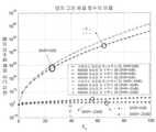
도2는 덧셈꼴 흰빛 정규 잡음 채널에서 이제까지의 셈과 제안한 어림셈으로 얻은 비율

Figure 112004511524703-pat00075
을 zn의 함수로 나타낸 도면.Fig. 2 shows the ratios of the previous calculations and the proposed approximation in the additive white normal noise channel.
Figure 112004511524703-pat00075
Plots as a function of zn .

도3은

Figure 112004511524703-pat00076
=10인 감쇄 채널에서 이제까지의 셈과 제안한 어림셈으로 얻은 비율
Figure 112004511524703-pat00077
의 차이를 zn의 함수로 나타낸 도면.3 is
Figure 112004511524703-pat00076
The ratio obtained by the previous calculation to the proposed approximation in the attenuation channel with = 10
Figure 112004511524703-pat00077
A diagram of the difference as a function of zn .

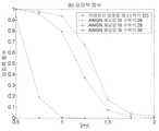
도4는 덧셈꼴 흰빛 정규 잡음 채널일 때 고정 표본 크기 검정 기법의 검파력함수를 나타낸 도면.Figure 4 shows the detection function of the fixed sample size test technique in the additive white normal noise channel.

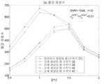
도5는 덧셈꼴 흰빛 정규 잡음 채널일 때 순차 확률비 검정 기법의 평균 표본수를 나타낸 도면.Fig. 5 shows the average number of samples of the sequential probability ratio test technique for the additive white light normal noise channel.

도6은 덧셈꼴 흰빛 정규 잡음 채널일 때 순차 확률비 검정 기법의 검파력 함수를 나타낸 도면.Figure 6 shows the detection function of the sequential probability ratio test technique for the additive white light normal noise channel.

도7은 덧셈꼴 흰빛 정규 잡음 채널일 때 끝을 자른 순차 확률비 검정 기법의 평균 표본수를 나타낸 도면.Figure 7 shows the average number of samples of a sequential probability ratio test technique with truncated edges in an additive white light normal noise channel.

도8은 덧셈꼴 흰빛 정규 잡음 채널일 때 끝을 자른 순차 확률비 검정 기법의 검파력 함수를 나타낸 도면.Figure 8 shows the detection function of the sequential probability ratio test technique truncated at the addition white normal noise channel.

도9는

Figure 112004511524703-pat00078
=10인 감쇄 채널일 때 고정 표본 크기 검정 기법의 검파력 함수를 나타낸 도면.9 is
Figure 112004511524703-pat00078
Depicts the power function of the fixed sample size test technique for attenuation channels with = 10.

도10은

Figure 112004511524703-pat00079
=10인 감쇄 채널일 때 순차 확률비 검정 기법의 평균 표본수를 나타낸 도면.10 is
Figure 112004511524703-pat00079
Figure showing the average number of samples of the sequential probability ratio test technique for attenuation channels with = 10.

도11은

Figure 112004511524703-pat00080
=10인 감쇄 채널일 때 순차 확률비 검정 기법의 검파력 함수를 나타낸 도면.11 is
Figure 112004511524703-pat00080
Diagram showing the detection function of the sequential probability ratio test technique for attenuation channels with = 10.

도12는

Figure 112004511524703-pat00081
=10인 감쇄 채널일 때 끝을 자른 순차 확률비 검정 기법의 평균 표본수를 나타낸 도면.Figure 12
Figure 112004511524703-pat00081
Figure showing the average number of samples of a sequential probability ratio test technique truncated at attenuation channel with = 10.

도13은

Figure 112004511524703-pat00082
=10인 감쇄 채널일 때 끝을 자른 순차 확률비 검정 기법의 검파력 함수를 나타낸 도면.Figure 13
Figure 112004511524703-pat00082
Diagram showing the detection function of the sequential probability ratio test technique truncated at attenuation channel of = 10.

이 발명은 직접수열 대역확산 시스템에서 순차 방법을 쓰는 비동위상 부호획득 방법에 관한 것으로서, 더 상세하게는 종래기술에서 최대 비슷함 추정을 쓰는 순차 부호획득 방법 대신에, 어림셈을 바탕으로 계산을 간단히 하여 실제 구현하기 쉬우면서도 그 성능이 비슷한 순차 부호획득 방법에 관한 것이다.The present invention relates to a non-phase code acquisition method using a sequential method in a direct sequence spread spectrum system. More specifically, instead of a sequential code acquisition method using a maximum likelihood estimation in the prior art, the calculation is simplified based on approximation. It is about a sequential code acquisition method that is easy to implement but has similar performance.

직접수열 대역확산 시스템에서 수신기는 들어오는 의사잡음 부호와 동기가 이루어진 국소 의사잡음 부호를 만들어야 한다. 수신기에서 받은 신호를 역확산하여 데이터를 제대로 얻으려면 무엇보다 먼저 이 두 부호 사이의 동기를 맞추어야 하므로, 부호 동기화는 모든 대역확산 시스템에서 꼭 필요한 과정이다. 이 부호 동기화 과정은 일반적으로 두 단계로 나뉜다. 부호획득이라 부르는 첫 단계에서는 두부호의 위상차를 한 칩보다 작게 맞춘다. 부호를 성공적으로 획득한 뒤에는 부호추적이라 부르는 둘째 단계에서 지연고정루프 (delay locked loop)나 타우-떨림루프(tau-dither loop)를 이용하여 두 부호의 위상차가 이상적으로 0이 될 때까지 정확하게 맞춘다. 이 발명에서는 부호획득 문제를 다룬다.In a direct sequence spread spectrum system, a receiver must produce a local pseudonoise code that is synchronized with the incoming pseudonoise code. Sign synchronization is a necessary process in all spread spectrum systems, because first, the signal must be synchronized between the two codes in order to despread the signal received from the receiver to obtain data properly. This code synchronization process is generally divided into two steps. In the first stage, called code acquisition, the phase difference of the two codes is made smaller than one chip. After the sign has been successfully acquired, the second step, called sign tracking, uses a delay locked loop or a tau-dither loop to accurately set the two phases until the phase difference is ideally zero. . This invention deals with the code acquisition problem.

부호획득 방법은 탐색 방법에 따라 직렬, 병렬, 그리고 혼합 방법으로 나뉜다. 직렬 탐색 방법은 하드웨어가 간단하지만, 주기가 긴 의사잡음 수열에서는 부호획득 시간이 매우 길어질 수 있다. 의사잡음 수열의 주기가 길 때 병렬 탐색 방법을 쓰면 부호를 빨리 획득할 수 있지만, 검파기 수가 그만큼 늘어나므로 하드웨어는 더욱 복잡해진다. 부호획득 시간과 하드웨어 측면에서 이 둘 사이의 성능을 보여주는 것이 혼합 탐색 방법이다. 한편, 부호획득 과정은 고정 우물 방법과 가변우물 방법으로 나눌 수 있고, 가변 우물 방법은 다시 여러 우물 방법과 순차 방법으로 나눌 수 있다. 고정 우물 방법 또는 고정 표본 크기 방법은 분석하기가 쉽고 병렬 탐색 방법과 직렬 탐색 방법 모두에 쓸 수 있다. 가변 우물 시간 방법은 분석하기가 어렵지만, 어떤 결정에 이르기까지 걸리는 평균 시간이 짧다는 점에서 고정우물 시간 방법보다 효율적이다.The code acquisition method is divided into serial, parallel, and mixed methods according to the search method. Although the serial search method is simple in hardware, the code acquisition time can be very long in a long period of pseudonoise sequences. The parallel search method can be used to obtain the code faster when the period of the pseudo noise sequence is long, but the hardware becomes more complicated as the number of detectors increases. The hybrid search method is to show the performance between the two in terms of code acquisition time and hardware. Meanwhile, the code acquisition process can be divided into a fixed well method and a variable well method, and the variable well method can be further divided into various well methods and sequential methods. The fixed well method or the fixed sample size method is easy to analyze and can be used for both parallel and serial search methods. The variable well time method is difficult to analyze, but is more efficient than the fixed well time method in that the average time to decision is short.

여러 해 동안 많은 사람들이 의사잡음 부호획득을 연구해 왔다. 특히, 여러 부호획득 방법들 가운데서도 순차 부호획득 방법을 쓸 때 성능이 가장 좋아질 수 있다는 것이 잘 알려져 있다. 순차 방법은 결정처리과정에서 문턱값을 두 개 쓴다. 하나는 두 의사잡음 부호의 동기가 이루어졌는지를 검사하는데 쓰이고, 다른 하나는 부호의 동기가 이루어지지 않아 계속 검사해야할 때 쓰인다. 적분기 출력을 바탕으로 부호 동기가 이루어졌는지 아닌지가 분명해지면 검사를 마치고 그에 알맞은 결정을 내린다. 그렇지 않을 때에는 계속 검사한다. 하지만 순차 부호획득 방법은 그 설계와 분석이 어렵기 때문에 그다지 연구가 덜 이루어진 것도 사실이다.For many years, many people have studied pseudo noise code acquisition. In particular, it is well known that among the various code acquisition methods, the performance can be best when the sequential code acquisition method is used. The sequential method uses two thresholds in the decision process. One is used to check whether the two pseudo-noise codes are synchronized, and the other is used when the code is not synchronized and must be checked continuously. Once it is clear whether or not sign synchronization is achieved based on the integrator output, the test is completed and the appropriate decision is made. If not, keep checking. However, since the sequential code acquisition method is difficult to design and analyze, it is true that less research has been conducted.

이제까지 순차 방법의 성능을 평가할 때에는 수치해석이나 컴퓨터 모의실험, 또는 어림셈을 바탕으로 한 간략화 방법을 써 왔다. 구체적인 한 보기로서, 덧셈꼴 흰빛 정규 잡음과 레일리 감쇄 채널에서 연속 적분기를 쓰는 동상/직교상 검파기를 바탕으로 비동위상 순차 부호획득을 할 때 성능이 어떤지는 모의실험으로만 조사되어 있다. 또 다른 보기로서, 성능 분석이 매우 어려운 순차 확률비 검정 기법 대신에, 신호대잡음비가 (signal-to-noise ratio: SNR) 낮을 때 순차 확률비 검정 기법과 성능이 다소 비슷한 편향 제곱합 (biased square-sum) 검파기를 고려하여 성능을 분석하고 쓰고 있다. 일반적으로 최대 비슷함 추정을 쓰는 순차 부호획득 방법들은 그 설계와 분석이 어려울 뿐만 아니라, 계산이 매우 복잡하여 실제로 구현하기에는 어려운 점이 있다.So far, we have used numerical methods, computer simulations, or approximation-based simplified methods to evaluate the performance of sequential methods. As a specific example, simulations show only the performance of non-phased sequential code acquisition based on additive white normal noise and in-phase orthogonal detectors with continuous integrators in Rayleigh attenuation channels. As another example, instead of the sequential probability test technique, which is very difficult to analyze, a biased square-sum is similar in performance to the sequential probability ratio test technique when the signal-to-noise ratio (SNR) is low. ) We analyze and write performance considering detector. In general, sequential code acquisition methods that use maximum likelihood estimation are not only difficult to design and analyze, but also very difficult to implement due to the complexity of computation.

이제, 도1을 참고로 하여 종래기술에 따른 부호획득 시스템을 자세히 살펴보기로 한다. 송신 신호는 덧셈꼴 흰빛 정규 잡음 채널과 느리게 바뀌는 감쇄 채널의 영향을 받는다. 부호를 획득하는 동안에는 변조된 데이터가 없다고 가정하면, 수신 신호 w(t)는 수학식 1과 같다.Now, the code acquisition system according to the prior art will be described in detail with reference to FIG. 1. The transmitted signal is affected by an additive white normal noise channel and a slowly changing attenuation channel. Assuming that there is no modulated data while acquiring the sign, the received signal w (t) is expressed byEquation 1 below.

Figure 112004511524703-pat00083

수학식 1에서, A0은 신호 크기,

Figure 112004511524703-pat00084
는 감쇄 확률변수, c(t)는 의사잡음 신호, 정수 i는 초기 위상 수, Δ는 시간을 나타내는 진행 단계의 크기, Tc는 칩 폭, ω0은 반송파 각주파수, θ는 [0,2π)에서 고르게 퍼져있는 확률 위상, 그리고 n(t)는 한쪽 전력밀도함수가 N0인 덧셈꼴 흰빛 정규 잡음이다. 보통, Δ는 1 또는 1/2로 쓰는데, 이는 검사마다 부호획득이 이루어지지 않았을 때 수신기에서 만든 의사잡음 수열을 각각 Tc 또는 Tc/2만큼 왼쪽으로 움직이는 것을 뜻한다.InEquation 1, A0 is the signal magnitude,
Figure 112004511524703-pat00084
Is the attenuation probability variable, c (t) is the pseudo-noise signal, integer i is the initial phase number, Δ is the magnitude of the advancing step representing time, Tc is the chip width, ω0 is the carrier angular frequency, and θ is [0,2π The probability phase spreading evenly, and n (t) is additive white normal noise with one power density function N0 . Usually, Δ is written as 1 or 1/2, which means that when no code acquisition is done for each test, the pseudonoise sequence produced by the receiver moves left by Tc or Tc / 2, respectively.

감쇄 확률변수

Figure 112004511524703-pat00085
의 확률밀도함수는 아래 수학식 2와 같이 라이시안 확률밀도함수라 둔다.Attenuation random variable
Figure 112004511524703-pat00085
The probability density function of is set as the Rician probability density function as shown inEquation 2 below.

Figure 112004511524703-pat00086

여기서,

Figure 112004511524703-pat00087
=s2/(2σ2)은 바로 들어오는 성분의 전력과 (s2) 흩어져 들어오는 성분의 전력의 (2σ2) 비율이고 s2 + 2σ2=1을 만족시키며,
Figure 112004511524703-pat00088
는 1종 0차 고친 베셀 함수이다. 수학식 2에서 아래 수학식 3을 쓰면
Figure 112004511524703-pat00089
라는 것을 쉽게 알 수 있다.here,
Figure 112004511524703-pat00087
= s2 / (2σ2) is sikimyeo immediately of incoming power and the component (s2) of the scattered power from the incoming component (2σ2) ratio and satisfy s2 + 2σ2 = 1,
Figure 112004511524703-pat00088
Is a first-order zero-corrected Bessel function. If you write Equation 3 below
Figure 112004511524703-pat00089
It is easy to see that.

Figure 112004511524703-pat00090

한편,

Figure 112004511524703-pat00091
=0이면
Figure 112004511524703-pat00092
는 레일리 감쇄 확률변수인데 이때 수학식 2를 아래와 같은 수학식 4로 쓸 수 있다.Meanwhile,
Figure 112004511524703-pat00091
= 0
Figure 112004511524703-pat00092
Is a Rayleigh attenuation probability variable, whereEquation 2 can be written asEquation 4 below.

Figure 112004511524703-pat00093

이를 바탕으로 도1을 설명하면, 먼저 수신 신호 w(t)의 주파수를 낮춰 바탕대역 동상 성분과 직교상 성분을 얻는다. 그런 뒤, 정합 여파기에서는 nTc초 동안 수신기에서 만든 의사잡음 부호수열과 바탕대역 동상/직교상 성분들을 상관짓는다. 이제 두 정합 여파기 상관기들의 출력을 제곱하고 더하여 정합 여파 수신기의 검정통계량 Yn을 얻는다. 결정 처리기는 Yn을 바탕으로 수신기에서 만든 의사잡음 신호와 들어오는 의사잡음 신호가 정렬되었는지 아닌지를 검사한다. 대략 정렬되었다면 동기화 과정은 부호 추적 과정으로 바뀌고, 그렇지 않으면, 국소 의사잡음 발생기의 위상을 ΔTc만큼 앞당긴 뒤 획득과정을 되풀이한다.Referring to FIG. 1, first, the frequency of the received signal w (t) is lowered to obtain a baseband in-phase component and a quadrature component. The matched filter then correlates the pseudonoise code sequences produced by the receiver with the baseband in-phase or quadrature components for nTc seconds. Now square the outputs of the two matched filter correlators and add them to obtain the test statistic Yn of the matched filter receiver. The decision processor checks whether or not the pseudonoise signal produced by the receiver and the incoming pseudonoise signal are aligned based on Yn . If roughly aligned, the synchronization process changes to a code tracking process, otherwise the phase of the local pseudonoise generator is advanced by ΔTc and the acquisition process is repeated.

수신기에서 만든 의사잡음 신호의 위상을 (i+

Figure 112004511524703-pat00094
)ΔTc라 둔다. 여기서, j는 정수이고
Figure 112004511524703-pat00095
∈(-1/2,1/2]는 나머지 부호 위상차이다. 이제 주파수가 두 배인 부분을 무시하면, 비동위상 상관기의 동상과 직교상 가지들의 출력은 각각 수학식 5와 6으로 나타난다.The phase of the pseudo-noise signal produced by the receiver (i +
Figure 112004511524703-pat00094
) ΔTc . Where j is an integer
Figure 112004511524703-pat00095
-1 (-1 / 2,1 / 2) is the remainder of the code phase difference, ignoring the doubled frequency, the output of the in-phase and quadrature branches of the non-phase correlator are represented byEquations 5 and 6, respectively.

Figure 112004511524703-pat00096

Figure 112004511524703-pat00006

수학식 5와 6에서 신호 성분은 수학식 7로, 동상과 직교상 잡음 성분은 각각 수학식 8과 9로 쓸 수 있다.InEquations 5 and 6, signal components may be written asEquations 7, and in-phase and quadrature noise components may be written as Equations 8 and 9.

Figure 112004511524703-pat00097

Figure 112004511524703-pat00098

Figure 112004511524703-pat00099

여기서, TcSn은 n칩에 걸친 의사잡음 신호의 부분 자기상관이고, Ni,n과 Nq,n은 평균이 0이고 분산이

Figure 112004511524703-pat00100
인 독립 정규 확률변수들이다. n과
Figure 112004511524703-pat00101
가 정해져 있을 때, 상관기 출력 Xi,n과 Xq,n은 평균이 각각
Figure 112004511524703-pat00102
Figure 112004511524703-pat00103
이고 분산이
Figure 112004511524703-pat00104
인 독립 정규 확률변수들이다.Where Tc Sn is the partial autocorrelation of the pseudonoise signal across n chips, where Ni ,n and Nq ,n are mean 0 and variance
Figure 112004511524703-pat00100
Are independent normal random variables. n and
Figure 112004511524703-pat00101
When is given, the correlator outputs Xi ,n and Xq ,n are averaged respectively.
Figure 112004511524703-pat00102
Wow
Figure 112004511524703-pat00103
And dispersion
Figure 112004511524703-pat00104
Are independent normal random variables.

도1에서 검정 통계량 Yn은 수학식 10과 같다.In FIG. 1, the test statistic Yn is represented byEquation 10. FIG.

Figure 112004511524703-pat00105

이 Yn은 비중심 카이-제곱 확률변수로서, 그 확률밀도함수는 아래 수학식11과 같다.Yn is a non-central chi-square random variable whose probability density function is represented byEquation 11 below.

Figure 112004511524703-pat00106

여기서,

Figure 112004511524703-pat00107
은 Yn이 포함하고 있는 신호 에너지를 나타내는 측도라 볼 수 있다. 검정 통계량 Yn의 누적분포함수는 수학식 12와 같다.here,
Figure 112004511524703-pat00107
Can be seen as a measure of the signal energy contained in Yn . The cumulative distribution function of the test statistic Yn is shown in Equation 12.

Figure 112004511524703-pat00108

여기서, Q(ㆍ,ㆍ)는 마컴 큐-함수로서 (Marcum's Q function)

Figure 112004511524703-pat00109
이다.Where Q (...,) is a Markham cue function (Marcum's Q function)
Figure 112004511524703-pat00109
to be.

정규화된 확률변수를

Figure 112004511524703-pat00110
이라 하고,
Figure 112004511524703-pat00111
,
Figure 112004511524703-pat00112
,그리고
Figure 112004511524703-pat00113
이라 두자. 그러면 수학식 11과 12를 바탕으로 Zn의 확률밀도함수와 누적분포함수를 아래 수학식 13과 14와 같이 다시 쓸 수 있다.Normalized random variables
Figure 112004511524703-pat00110
This is called,
Figure 112004511524703-pat00111
,
Figure 112004511524703-pat00112
,And
Figure 112004511524703-pat00113
Let's keep it. Then, based onEquations 11 and 12, the probability density function and the cumulative distribution function of Zn can be rewritten as Equations 13 and 14 below.

Figure 112004511524703-pat00012

Figure 112004511524703-pat00114

여기서,

Figure 112004511524703-pat00115
=0이면 (레일리 감쇄일 때), In(0)=1이고
Figure 112004511524703-pat00116
이며 아래 수학식 15를 얻는다.here,
Figure 112004511524703-pat00115
= 0 (when Rayleigh attenuation), In (0) = 1
Figure 112004511524703-pat00116
And the following equation (15) is obtained.

Figure 112004511524703-pat00117

따라서

Figure 112004511524703-pat00118
=0일 때는 수학식 13과 14를 아래와 같이 수학식 16과 17로 쓸 수 있다.therefore
Figure 112004511524703-pat00118
When = 0, Equations 13 and 14 can be written asEquations 16 and 17 as follows.

Figure 112004511524703-pat00119

Figure 112004511524703-pat00120

한편, 감쇄가 없다면 (

Figure 112004511524703-pat00121
→∞), (1+
Figure 112004511524703-pat00122
)/qn→1,
Figure 112004511524703-pat00123
/qn→1, 그리고
Figure 112004511524703-pat00124
이므로, Zn은 카이-제곱 확률변수이고, 그 확률밀도함수와 누적분포함수는 각각 수학식 18과 19와 같다.On the other hand, if there is no attenuation (
Figure 112004511524703-pat00121
→ ∞), (1+
Figure 112004511524703-pat00122
) / qn → 1,
Figure 112004511524703-pat00123
/ qn → 1, and
Figure 112004511524703-pat00124
Since Zn is a chi-square random variable, the probability density function and the cumulative distribution function are represented by Equations 18 and 19, respectively.

Figure 112004511524703-pat00125

Figure 112004511524703-pat00126

순차 결정 처리기는 Zn을 바탕으로 들어오는 의사잡음 신호와 수신기에서 만든 의사잡음 신호의 위상차가 ΔTc/2보다 작은지 (곧, j=i), 두 신호의 위상차가 적어도 한 칩보다 큰지 (곧,

Figure 112004511524703-pat00127
), 또는 ΔTc/2보다 크고 한 칩보다 작은지를 정한다. 먼저, i=0이라 두면 위상차는 j+
Figure 112004511524703-pat00128
이다. 곧, 결정 처리기는 아래 가설들 가운데 하나를 고르는 것이다:The sequential decision processor determines whether the phase difference between the incoming pseudonoise signal and the pseudonoise signal produced by the receiver based on Zn is less than ΔTc / 2 (ie, j = i), and the phase difference between the two signals is greater than at least one chip ( ,
Figure 112004511524703-pat00127
), Or greater than ΔTc / 2 and less than one chip. First, if i = 0, the phase difference is j +
Figure 112004511524703-pat00128
to be. In short, the decision processor chooses one of the following hypotheses:

Figure 112004511524703-pat00019

여기서,

Figure 112004511524703-pat00129
이므로 H0과 H1은 복합 가설들이고, 일반적으로 λn
Figure 112004511524703-pat00130
과 가설에 따라 값이 다르다. 그러므로, 가장 상황이 나쁜 때에 대비하고자 H0에서 가장 큰 λn값을 λn,0, H1에서 가장 작은 λn값을 λn,1이라고 두자. 그러면, λn,1>λn,0이고, λn,0과 λn,1은 가장 나쁜 상황일 때 값들이다. 늘어난 아래첨자 0이나 1은 각각 H0 또는 H1에서 매개변수 εn이나 qn을 나타낸다: 보기를 들면, εn,0는 H0에서 매개변수 εn을 뜻한다.here,
Figure 112004511524703-pat00129
H0 and H1 are complex hypotheses, and λn is generally
Figure 112004511524703-pat00130
The value depends on and hypothesis. Therefore, the situation is bad Let itfirst to the largest λn λn the smallest value of the value in then λ,0, H1, H at λ0n, compared to the time. Then, λn ,1 > λn ,0 , and λn ,0 and λn ,1 are the values in the worst case. Theextended subscripts 0 or 1 represent the parameters εn or qn at H0 or H1 , for example: εn ,0 represent the parameters εn at H0 .

이제 비슷함 비율을 수학식 21과 같이 쓸 수 있다.The similarity ratio can now be written as

Figure 112004511524703-pat00020

한편, 감쇄가 없을 때에는 (

Figure 112004511524703-pat00131
→∞), 수학식 21을 아래와 같은 수학식 22로 쓸 수 있다.On the other hand, when there is no attenuation (
Figure 112004511524703-pat00131
→ ∞), Equation 21 can be written as Equation 22 below.

Figure 112004511524703-pat00132

베셀 함수와 지수함수는 계산이 복잡하므로, 수학적 21과 22는 실시간으로 구현하기가 어렵다. 특히, 베셀 함수는 지수함수와 삼각함수의 적분으로 나타나기 때문에, 복잡한 계산을 많이 해야 이를 풀 수 있다. 게다가 베셀 함수는 닫힌꼴로 쓸 수 없으므로, 베셀 함수의 독립변수가 주어질 때 답을 얻으려면 수치 적분 방식이나 어림셈 점근 방법을 써야만 한다.Because Bessel and exponential functions are complex, mathematical expressions 21 and 22 are difficult to implement in real time. In particular, since the Bessel function is expressed as the integral of the exponential and trigonometric functions, it must be solved with a lot of complicated calculations. In addition, the Bessel function cannot be used in closed form, so you have to use numerical integration or approximation asymptotic to get an answer when the Bessel function's independent variable is given.

이 발명에서는 이상과 같은 종래기술의 문제점을 감안하여, 실시간으로 구현가능하면서도 그 성능이 종래의 부호획득 방법과 비슷한 간단한 순차 부호획득 방법을 제공하여 이를 직접수열 대역확산 시스템에 적용하고자 한다. 이는 순차 부호획득방법을 쓸 때 최대 비슷함 비율에서 나타나는 베셀 함수를 때에 따라 알맞게 어림잡음으로써 달성할 수 있다.In view of the problems of the prior art, the present invention provides a simple sequential code acquisition method that can be implemented in real time and similar in performance to a conventional code acquisition method, and applied to a direct sequence spread spectrum system. This can be achieved by timely approximating the Bessel function that appears at the maximum likelihood ratio when using sequential code acquisition.

이제, 본 발명을 구체적으로 설명하기로 한다.Now, the present invention will be described in detail.

0차로 변경한 베셀 함수 I0(

Figure 112004511524703-pat00133
)는 수학식 23과 같이 어림잡을 수 있다.Bessel function changed tozero order I0 (
Figure 112004511524703-pat00133
) May be approximated as in Equation 23.

Figure 112004511524703-pat00022

수학식 23에서 얻은 두 어림셈을 바탕으로, 감쇄 채널과 덧셈꼴 흰빛 정규 잡음 채널일 때 각각 수학식 21과 22의 Λn(zn)을 간단하게 한 어림셈을 만든다.Based on the two approximations obtained in Equation 23, we make a simple approximation of Λn (zn ) in Equations 21 and 22 for the attenuation channel and the addition white normal noise channel, respectively.

먼저, 덧셈꼴 흰빛 정규 잡음 (감쇄가 없는) 채널일 때 수학식 22에 있는 I0(ㆍ)의 비는 수학식 24와 같다.First, the ratio of I0 (·) in Equation 22 when the additive white normal noise (no attenuation) channel is represented by Equation 24.

Figure 112004511524703-pat00023

여기서, zn은 음 아닌 확률변수 Zn의 실현이고, 이 값을 미리 알 수 없으므로, 수학식 23에서 얻은 두 어림셈을 수학식 24의 분자와 분모에 넣을 때 얻을 수 있는 모든 것을 따져 본다.Here, zn is the realization of the non-negative random variable Zn , and since this value is not known in advance, it examines everything that can be obtained when the two approximations obtained in Equation 23 are put into the numerator and denominator of Equation 24.

첫째 어림셈을 얻고자 수학식 24의 분자와 분모에

Figure 112004511524703-pat00134
를 넣으면 아래 수학식 25를 얻는다.To get the first rule of thumb, let's look at the numerator and denominator
Figure 112004511524703-pat00134
If you put in, you get Equation 25 below.

Figure 112004511524703-pat00135

이를 쓰면, 수학식 22로 나타나는 비슷함 비율은 아래 수학식 26과 같이 간단해진다.Using this, the similarity ratio represented by Equation 22 is simplified as shown inEquation 26 below.

Figure 112004511524703-pat00136

여기서, '

Figure 112004511524703-pat00137
'는 ' 이와 같이 쓸 수 있다' 를 뜻한다.here, '
Figure 112004511524703-pat00137
'Means you can write like this'.

둘째 어림셈을 얻고자, 수학식 24의 분자와 분모에 각각

Figure 112004511524703-pat00138
Figure 112004511524703-pat00139
를 넣으면 수학식 24는 수학식 27과 같이 다시 쓸 수 있다.To get the second approximation, each of the numerator and denominator
Figure 112004511524703-pat00138
Wow
Figure 112004511524703-pat00139
Equation 24 can be rewritten as Equation 27.

Figure 112004511524703-pat00026

따라서, 수학식 22의 Λn(zn)을 아래와 같이 수학식 28로 다시 쓸 수 있다.Therefore, Λn (zn ) of Equation 22 can be rewritten asEquation 28 as follows.

Figure 112004511524703-pat00140

셋째 어림셈을 얻고자, 수학식 24의 분자와 분모에

Figure 112004511524703-pat00141
을 넣으면 수학식 24를 아래와 같은 수학식 29로 어림잡을 수 있다.To get the third approximation, the numerator and denominator
Figure 112004511524703-pat00141
Equation (24) can be approximated by Equation (29) below.

Figure 112004511524703-pat00142

이 어림셈을 바탕으로 수학식 22를 수학식 30과 같이 다시 쓸 수 있다.Based on this approximation, Equation 22 can be rewritten asEquation 30.

Figure 112004511524703-pat00143

한편,

Figure 112004511524703-pat00144
이므로 수학식 24의 분자와 분모에 각각
Figure 112004511524703-pat00145
Figure 112004511524703-pat00146
를 넣는 것은 쓸모 없다. 덧셈꼴 흰빛 정규 잡음 채널일 때 제안한 어림셈에서 얻은 비율
Figure 112004511524703-pat00147
을 도2에 나타내었다. 도2에서 칩 당 신호대잡음비는
Figure 112004511524703-pat00148
라 정하였고, 수학식 31과 32와 같은 어림셈들을 썼다.Meanwhile,
Figure 112004511524703-pat00144
Since the numerator and denominator in equation (24)
Figure 112004511524703-pat00145
Wow
Figure 112004511524703-pat00146
Putting it in is useless. Proportion from Proposed Estimation for Additive White Noise Channel
Figure 112004511524703-pat00147
Is shown in FIG. In Figure 2, the signal-to-noise ratio per chip is
Figure 112004511524703-pat00148
The equations such as Equations 31 and 32 were used.

Figure 112004511524703-pat00030

Figure 112004511524703-pat00149

이 도2에서는, 나머지 부호 위상차가 가장 나쁜 때로서

Figure 112004511524703-pat00150
=1/2을 썼고, n=100과 Δ=1/2을 썼다. 여기서, n값을 달리해도 도2의 일반적인 경향이 거의 바뀌지 않는다는 것을 모의실험으로 알았기에, 대표값으로 n=100을 썼다. 신호대잡음비가 -20dB보다 낮을 때 제안한 모든 어림셈들(수학식 26, 28, 30)과 종래의 어림하지 않은 방법 (수학식 22)을 비교해 보면 비율들이 모두 비슷하게 커지는 특성을 보인다. 신호대잡음비가 높아지면, 수학식 22, 수학식 26, 그리고 수학식 28에서는 비율이 커지는 특성을 보이지만, 수학식 30에서는 수학식 22로 얻은 것과 달리 비교적 작은 값으로 유지된다.In Fig. 2, when the remaining code phase difference is the worst,
Figure 112004511524703-pat00150
= 1/2, n = 100 and Δ = 1/2. Here, the simulation found that the general tendency of Fig. 2 hardly changed even if the value of n was different, and n = 100 was used as the representative value. When the signal-to-noise ratio is lower than -20dB, all of the proposed equations (Equations 26, 28, 30) and the conventional unestimate method (Equation 22) show similar ratios. When the signal-to-noise ratio is increased, the ratios are increased inEquations 22, 26, and 28, but are kept relatively small inEquation 30, unlike those obtained in Equation 22.

수학식 28에서 얻은 비율들은 신호대잡음비와 무관하게 다른 방법들로 얻은 것보다 빠르게 커진다. 이것은 zn이 정해졌을 때, 수학식 28로 얻은 Λn(zn)이 다른 방법들로 얻은 것보다 더 크다는 것을 뜻한다. 그러므로, 수학식 28로 얻은 Λn(zn)이 어떤 문턱값보다 클 확률이 다른 방법들에서보다 높고, 결국 더 자주 H1을 받아들인다. 다른 측면에서 본다면, Λn(zn)이 어떤 문턱값보다 작기를 바랄 때 (즉, H0를 받아들이고자 할 때), 수학식 28을 쓰면 반대 결과를 얻을 수도 있다.The ratios obtained inEquation 28 grow faster than those obtained by other methods regardless of the signal-to-noise ratio. This means that when zn is determined, Λn (zn ) obtained byEquation 28 is larger than that obtained by other methods. Therefore, the probability that Λn (zn ) obtained byEquation 28 is greater than some threshold is higher than in other methods, and eventually receives H1 more often. On the other hand, if we want Λn (zn ) to be smaller than some threshold (that is, we want to accept H0 ), we can get the opposite result by using equation (28).

앞에서 덧셈꼴 흰빛 정규 잡음 채널일 때 어림한 것과 같이, 이제부터는 감쇄채널일 때 비슷함 비율인 수학식 21을 어림잡아 본다. 먼저, 수학식 21로 나타나는 최대 비슷함 비율에서 0차 고친 베셀 함수의 비율은 수학식 33과 같다.As we estimated earlier with the additive white normal noise channel, we now estimate Equation 21, which is the similarity ratio for the attenuation channel. First, the ratio of the zero order-corrected Bessel function at the maximum likelihood ratio represented by Equation 21 is expressed by Equation 33.

Figure 112004511524703-pat00032

먼저, 감쇄 채널일 때 첫째 어림셈을 얻고자, 수학식 33의 분자와 분모에

Figure 112004511524703-pat00151
를 넣으면, 수학식 34를 얻는다.First, to get the first approximation in the attenuation channel, the numerator and denominator
Figure 112004511524703-pat00151
If we put in, we get (34).

Figure 112004511524703-pat00152

그러면, 수학식 21을 수학식 35와 같이 다시 쓸 수 있다.Then, Equation 21 may be rewritten as Equation 35.

Figure 112004511524703-pat00153

Figure 112004511524703-pat00154

여기서, δn은 아래 수학식 36과 같다.Here, δn is represented by Equation 36 below.

Figure 112004511524703-pat00155

다음으로 감쇄 채널일 때 둘째 어림셈을 얻고자, 수학식 33의 분자와 분모에 각각 어림셈

Figure 112004511524703-pat00156
Figure 112004511524703-pat00157
를 넣으면 수학식 37을 얻는다.Next, to obtain the second approximation in the attenuation channel, the numerator and denominator in Eq.
Figure 112004511524703-pat00156
Wow
Figure 112004511524703-pat00157
If you put the equation (37).

Figure 112004511524703-pat00158

이 어림셈을 쓰면, 수학식 21을 수학식 38과 같이 쓸 수 있다.Using this approximation, Equation 21 can be written as Equation 38.

Figure 112004511524703-pat00159

Figure 112004511524703-pat00160

감쇄 채널일 때 셋째 어림셈을 얻고자, 수학식 33의 분자와 분모에 각각 어림셈

Figure 112004511524703-pat00161
Figure 112004511524703-pat00162
를 넣으면 수학식 39를 얻는다.To obtain the third approximation in the attenuation channel, the numerator and denominator in Eq.
Figure 112004511524703-pat00161
and
Figure 112004511524703-pat00162
If you put the equation (39).

Figure 112004511524703-pat00040

이 어림셈을 쓰면, 수학식 21은 아래와 같은 수학식 40으로 다시 쓸 수 있다.Using this approximation, Equation 21 can be rewritten asEquation 40 below.

Figure 112004511524703-pat00041

마지막으로 감쇄 채널일 때 넷째 어림셈을 얻고자, 수학식 33의 분자와 분모에

Figure 112004511524703-pat00163
를 넣으면 수학식 41과 같다.Finally, to get the fourth approximation in the attenuation channel, the numerator anddenominator
Figure 112004511524703-pat00163
Equation
41 is shown inEquation 41.

Figure 112004511524703-pat00042

위 어림셈을 쓰면, 수학식 21의 비슷함 비율 Λn(zn)은 수학식 42와 같이 쓸 수 있다.Using the above approximation, the similarity ratio Λn (zn ) in Equation 21 can be written as Equation 42.

Figure 112004511524703-pat00164

덧셈꼴 흰빛 정규 잡음 채널일 때와 다르게 감쇄 채널일 때에는 수학식 33의 분자와 분모에 각각 어림셈

Figure 112004511524703-pat00165
Figure 112004511524703-pat00166
도 넣어 어림하였다. 왜냐하면, 네 매개변수들,
Figure 112004511524703-pat00167
,
Figure 112004511524703-pat00168
,
Figure 112004511524703-pat00169
, 그리고
Figure 112004511524703-pat00170
의 값이 바뀌면
Figure 112004511524703-pat00171
일 수도 있고
Figure 112004511524703-pat00172
일 수도 있기 때문이다. 감쇄 채널일 때 제안한 어림셈들을 써서 얻은 비율, 수학식 33을
Figure 112004511524703-pat00173
=10일 때 그림3에 보였다. 수학식 21, 수학식 35, 그리고 수학식 38에서 얻은 I0(ㆍ)의 비율들은 신호대잡음비가 낮을 때 비슷하게 커지는 특성이 있으나, 수학식 40과 수학식 42에서 얻은 I0(ㆍ)의 비율들은 그와 같은 특성이 없다. 신호대잡음비가 높을 때, 비록 수학식 38에서 얻은 비율이 다른 방법으로 얻은 것보다 조금 높기는 하지만, 수학식 21, 수학식 35, 그리고 수학식 38에서 얻은 비율들은 여전히 비슷한 형태를 보인다. 한편, 수학식 40과 42에서 얻은 비율들은 이제까지의 방법, 곧 수학식 21에서 얻은 비율과 달리 낮은 값으로 일정하다. 이 결과를 바탕으로, 앞의 덧셈꼴 흰빛 정규 잡음 때 말한 것과 비슷하게 수학식 35와 38이 수학식 40과 42보다 성능 이 더 나을 것임을 미리 알수 있다.Unlike the addition white normal noise channel, the attenuation channel is estimated by the numerator and denominator of Eq.
Figure 112004511524703-pat00165
and
Figure 112004511524703-pat00166
Also estimated. Because four parameters,
Figure 112004511524703-pat00167
,
Figure 112004511524703-pat00168
,
Figure 112004511524703-pat00169
, And
Figure 112004511524703-pat00170
If the value of changes
Figure 112004511524703-pat00171
Could be
Figure 112004511524703-pat00172
Because it may be. For the attenuation channel, the ratio obtained by using the proposed approximations,
Figure 112004511524703-pat00173
It is shown in Figure 3 when = 10. The ratios of I0 (·) obtained in Equations 21, 35, and 38 are similarly large when the signal-to-noise ratio is low, but the ratios of I0 (·) obtained inEquations 40 and 42 are There is no such characteristic. When the signal to noise ratio is high, the ratios obtained from Equations 21, 35, and 38 are still similar, although the ratios obtained from Equation 38 are slightly higher than those obtained by other methods. On the other hand, the ratios obtained in equations (40) and (42) are constant at low values, unlike the methods obtained so far, the ratios in equation (21). Based on these results, it can be seen in advance that Equations 35 and 38 will perform better thanEquations 40 and 42, similar to what was said with the addition white noise.

이 발명에서 고려한 세 결정처리기는 고정 표본 크기 검정 기법과 순차 확률에 검정 기법, 그리고 끝을 자른 순차 확률비 검정 기법이다. 먼저, 고정 표본 크기 결정 방법에서는 정해진 길이만큼 적분하여 얻은 검정 통계량을 바탕으로 결정을 내린다. 적분구간이 0부터 MTc일 때, 고정 표본 크기 검정 기법에서는 검정 통계량의 ΛM(zM)을 계산하고, 문턱값

Figure 112004511524703-pat00174
와 견주어 본 뒤, ΛM(zM)≥
Figure 112004511524703-pat00175
이면 H1로 결정하고 그렇지 않으면 H0으로 결정한다. 곧, 고정 표본 크기 검정 기법은 아래와 같이 쓸 수 있다.The three decision processors considered in this invention are the fixed sample size test method, the sequential probability test method, and the truncated sequential probability ratio test method. First, in the fixed sample size determination method, the decision is made based on the test statistic obtained by integrating by a predetermined length. When the integration interval is from 0 to MTc , the fixed sample size test technique calculates ΛM (zM ) of the test statistic, and the threshold
Figure 112004511524703-pat00174
After comparing with, ΛM (zM ) ≥
Figure 112004511524703-pat00175
If it is, it is determined as H1 , otherwise it is determined as H0 . In short, the fixed sample size test can be written as

Figure 112004511524703-pat00044

다음으로, 순차 확률비 검정 기법 방법에서는, n=1, 2, 3,…으로 늘어날 때, 비슷함 비율 Λn(zn)이 두 문턱값 A와 B (A>B>0) 가운데 어느 한 문턱값에 이를 때까지 Λn(zn)과 두 문턱값을 견주어 본다. 여기서, Λn(zn)≥A이면 H1을 받아들이고, Λn(zn)≤B이면 H0을 받아들인다. 그밖에는, 곧, A<Λn(zn)<B일 때에는, 결정을 하지않고 한 칩 폭만큼 더 적분하여 검정 기법을 계속한다. 다시 말해, 순차 확률비 검정 기법은 수학식 44와 같이 쓸 수 있다:Next, in the sequential probability ratio test method, n = 1, 2, 3,... When the increase, likelihood ratio Λn (zn) a watch gyeonjueo the two threshold values A and B (A>B> 0) of Λn (zn) with the two threshold values up to the any one of the threshold value. Here, if Λn (zn) ≥A accept the H1, if Λn (zn) ≤B accept H0. Otherwise, when A <Λn (zn ) <B, the test technique is continued by integrating by one chip width without making a decision. In other words, the sequential probability ratio test can be written as (44):

Figure 112004511524703-pat00045

순차 확률비 검정 기법에서는 검사 길이에 끝이 없다는 것이 단점이다. 그러므로, H0이나 H1이 아닌 값을 받으면, 결정 처리기는 매우 긴 시간 동안 결정을 내리지 못할 수 있다. 따라서, H0이나 H1이 아닌 값을 받았을 때 지나치게 오랜 시간동안 검사하는 것을 막고자, 검사 길이에 위쪽 끝

Figure 112004511524703-pat00176
을 둔 끝을 자른 순차 확률비 검정 기법을 쓸 수 있다.The disadvantage of the sequential probability ratio test is that there is no end to the test length. Therefore, if a value other than H0 or H1 is received, the decision processor may not be able to make a decision for a very long time. Therefore, to avoid testing for too long when a value other than H0 or H1 is received, the upper end of the test length
Figure 112004511524703-pat00176
We can use a sequential probability test that cuts the ends of

Figure 112004511524703-pat00046

곧, 검사 길이가

Figure 112004511524703-pat00177
에 이를 때까지 검사가 끝나지 않았다면, n=
Figure 112004511524703-pat00178
에서 검사를 멈추고 결정을 내린다.Soon, inspection length
Figure 112004511524703-pat00177
If the test is not completed by the time n, n =
Figure 112004511524703-pat00178
Stops the test and makes a decision.

이제, 제안한 방법들과 이제까지의 방법의 평균 표본수와 검파력 함수를 바탕으로 그 성능을 비교해 본다. 평균 표본수는 검사가 끝날 때까지 쓰는 평균 칩 수를 뜻하고 검파력 함수는 H1을 받아들일 확률을 뜻한다. 아래와 같은 매개변수들 을 써서 성능을 평가한다.Now, we compare the performance of the proposed methods with the average number of samples and the detection function. The average number of samples is the average number of chips used until the end of the test, and the detection function is the probability of accepting H1 . Use the following parameters to evaluate performance.

1) 원시 다항식

Figure 112004511524703-pat00179
을 써서 얻어 길이가 1023칩인 의사잡음 수열;1) primitive polynomials
Figure 112004511524703-pat00179
Pseudo noise sequence of length 1023 chips obtained using

2) 칩 신호대잡음비=-10dB;2) chip signal-to-noise ratio = -10dB;

3) 진행 단계의 크기 Δ=1/2;3) the magnitude Δ = 1/2 of the progression step;

4) 나머지 부호 위상차

Figure 112004511524703-pat00180
=1/2.4) remaining code phase difference
Figure 112004511524703-pat00180
= 1/2.

수학식 22, 26, 28, 그리고 30을 바탕으로, 덧셈꼴 흰빛 정규 잡음일 때 이제까지의 부호획득 방법과 이 발명에서 제안한 간단한 비동위상 순차 부호획득 방법들의 성능을 도 4 내지 8에 나타내었다. 이 도면들에서, 고정 표본 크기 검정 기법과 순차 확률비 검정 기법, 그리고 끝을 자른 순차 확률비 검정 기법은 αdd=0.005일 때 설계된 것이고, 끝을 자른 순차 확률비 검정 기법은 ρ01=0.5를 써서 얻은 것이다. 여기서, αd와 βd는 시스템에 바라는 오경보 확률과 버림 확률이고, ρ0과 ρ1은 끝을 자른 순차 확률비 검정 기법의 설계 상수들이다. 만약 ρ01=0이면, 끝을 자른 순차 확률비 검정 기법은 고정 표본 크기 검정 기법과 같아지고, ρ01=1이면, 끝을 자른 순차 확률비 검정 기법은 순차 확률비 검정 기법과 같아진다. 끝을 자른 순차 확률비 검정 기법은 ρ0과 ρ1에 따라 순차 확률비 검정 기법과 고정 표본 크기 검정 기법을 섞은 것으로 볼 수 있다. 이 도면들에서, 가설 H1과 H0은 각각

Figure 112004511524703-pat00181
Figure 112004511524703-pat00182
을 뜻한다. 이 도면들을 통해 볼 때, 수 학식 28은 다른 어림셈들(수학식 26과 30)이나 이제까지의 방법(수학식 22)의 성능이 좋음을 알 수 있다.Based on the equations (22), (26), (28), and (30), the performance of the conventional code acquisition method and the simple non-phase sequential code acquisition methods proposed by the present invention when the additive white light normal noise is shown in FIGS. In these figures, the fixed sample size test, the sequential probability ratio test, and the truncated sequential probability ratio test are designed when αd = βd = 0.005, and the truncated sequential probability ratio test is ρ0. It is obtained by using = ρ1 = 0.5. Here, αd and βd are the false alarm probability and the discard probability desired by the system, and ρ0 and ρ1 are design constants of the sequential probability ratio test method. If ρ0 = ρ1 = 0, the truncated sequential probability test is equivalent to the fixed sample size test; if ρ0 = ρ1 = 1, the truncated sequential probability test is a sequential probability test It's like a technique. The truncated sequential probability test method can be seen as a mixture of sequential probability ratio test and fixed sample size test according to ρ0 and ρ1 . In these figures, hypotheses H1 and H0 are respectively
Figure 112004511524703-pat00181
Wow
Figure 112004511524703-pat00182
It means. It can be seen from these figures thatEquation 28 performs well with other approximations (Equations 26 and 30) or with the previous method (Equation 22).

수학식 28을 쓸 때 평균 표본수는 수학식 22를 쓸 때 보다 위상차에 관계없이 낮다. 또한 수학식 28의 검파력 함수 특성은

Figure 112004511524703-pat00183
일 때 수학식 22보다 좋지만,
Figure 112004511524703-pat00184
일 때에는 수학식 22보다 조금 나쁘다. 이 결과는 이미 앞에서 말한 것을 바탕으로 미루어 알 수 있다. 특히, 수학식 28은 이제까지의 방법으로 얻은 비슷함 비율, 즉 수학식 22보다 더 크므로, 위쪽 문턱값보다 클 확률이 더 높다. 결과적으로, 절대 위상차가 한 칩 폭의 절반보다 작을 (
Figure 112004511524703-pat00185
), 평균 표본수는 적어지고 검파력 함수의 성능 특성은 나아진다. 한편, 절대 위상차가 한 칩 구간의 절반보다 클때 (
Figure 112004511524703-pat00186
), 사건 {Λn(Zn)>위쪽 문턱값}은 수학식 22에서보다 수학식 28에서 더 자주 일어나므로 검파력 함수는 이제까지의 방법인 수학식 22일 때 보다 높다. 곧, 절대 위상차가 한 칩 폭의 절반보다 크면 검파력 함수 특성이 떨어진다.When using equation (28), the average number of samples is lower regardless of the phase difference than when using equation (22). In addition, the detection function characteristic ofEquation 28 is
Figure 112004511524703-pat00183
Is better than Equation 22,
Figure 112004511524703-pat00184
Is slightly worse than Eq. This result is based on what we have already said. In particular,Equation 28 is greater than the similarity ratio obtained by the methods so far, i.e., Equation 22, and therefore is more likely to be larger than the upper threshold. As a result, the absolute phase difference is less than half of one chip width (
Figure 112004511524703-pat00185
), The average number of samples is reduced and the performance characteristics of the detection function are better. On the other hand, when the absolute phase difference is greater than half of one chip section (
Figure 112004511524703-pat00186
), The event {Λn (Zn )> upper threshold} occurs more frequently inEquation 28 than in Equation 22, so the detection function is higher than in the previous method. In other words, if the absolute phase difference is greater than half the width of one chip, the detection function becomes poor.

다음으로, 감쇄 확률밀도함수

Figure 112004511524703-pat00187
를 안다고 가정할 때, 감쇄 환경에서 부호획득 방법들의 성능을 살펴 본다. 앞에서 감쇄를 고려해 얻은 확률밀도함수인 수학식 13을 써서 모든 검정 기법의 문턱값들을 알맞게 맞추었다. 감쇄가 알려졌을 때에 알맞게 설계된 고정 표본 크기 검정 기법과 순차 확률비 검정 기법, 그리고 끝을 자른 순차 확률비 검정 기법의 평균 표본수와 검파력 함수를 도9 내지 13에 나타내었다. 여기서,
Figure 112004511524703-pat00188
=10, αdd=0.01, 그리고 ρ01=0.5이다. 감쇄 채널에서
Figure 112004511524703-pat00189
이면 수학식 38의 성능이 가장 좋고,
Figure 112004511524703-pat00190
이면 수학식 35의 성능이 가장 좋은 것을 알 수 있다. 이 관측들도 이전과 같이 앞에서 말한 것을 바탕으로 미루어 알 수 있는 것이다.Next, the decay probability density function
Figure 112004511524703-pat00187
We assume that we know the performance of the code acquisition methods in the attenuation environment. Using the probability density function (Equation 13) obtained in consideration of the attenuation, the thresholds of all the test methods are appropriately adjusted. The average number of samples and the detection function of the fixed sample size test method, the sequential probability ratio test method, and the sequential probability ratio test method that are appropriately designed when the attenuation is known are shown in FIGS. here,
Figure 112004511524703-pat00188
= 10, αd = βd = 0.01, and ρ0 = ρ1 = 0.5. In the attenuation channel
Figure 112004511524703-pat00189
Equation 38 is the best performance,
Figure 112004511524703-pat00190
In this case, it can be seen that the performance of Equation 35 is the best. These observations can be understood based on the foregoing.

이상에서 살펴본 바와 같이 직접수열 대역확산 시스템에 알맞은 비동위상 순차 부호획득을 고정 표본 크기 검정 기법과 순차 확률비 검정 기법, 그리고 끝을 자른 순차 확률비 검정 기법과 함께 살펴보았다. 최대 비슷함 추정을 쓰는 부호획득 방법들은 구현하기에 알맞지 않다고 알려져 있기에, 이제까지의 부호획득 방법들을 바탕으로 감쇄가 있거나 없는 채널에서 쓸 수 있는 간단한 어림셈들을 만들어 실시간으로 구현할 수 있도록 하였다. 덧셈꼴 흰빛 정규 잡음 채널일 때 수학식 28, 감쇄 채널일 때 수학식 35와 38은 다른 어림셈들보다 성능이 뛰어났고, 이에 상응하는 종래기술의 부호획득 방법들보다 성능이 더 우수하다.As described above, the in-phase sequential code acquisition suitable for the direct sequence spreading system is examined along with the fixed sample size test, the sequential probability ratio test, and the truncated sequential probability ratio test. Since code acquisition methods using maximum likelihood estimation are known to be inadequate to implement, they can be implemented in real time by making simple approximations that can be used in channels with or without attenuation.Equation 28 for the additive white normal noise channel and Equations 35 and 38 for the attenuation channel outperformed other estimates, and outperformed the corresponding code acquisition methods of the prior art.

Claims (13)

Translated fromKorean
순차 의사잡음 부호획득에서 비동위상 상관기의 출력(Zn)을 바탕으로, 덧셈꼴 흰빛 정규잡음 채널일 때는 하기의 수학식28의 어림 최대 비슷함 비율을 사용하고, 감쇄 채널일 때는 하기의 수학식35의 어림 최대 비슷함 비율을 사용하는 것을 특징으로 하는 순차 의사잡음 부호획득의 의사잡음 동기 여부 판정 방법.Based on the output of the in-phase correlator (Zn ) in sequential pseudo-noise code acquisition, an approximate maximum likelihood ratio of Equation 28 is used for the addition white normal noise channel, and for the attenuation channel, A method for determining whether or not pseudo noise is synchronized by sequential pseudo noise code acquisition, using an approximation maximum likelihood ratio of 35.
Figure 112006034387869-pat00192
순차 의사잡음 부호획득에서 비동위상 상관기의 출력(Zn)을 바탕으로, 덧셈꼴 흰빛 정규잡음 채널일 때는 하기의 수학식28의 어림 최대 비슷함 비율을 사용하고, 감쇄 채널일 때는 하기의 수학식38의 어림 최대 비슷함 비율을 사용하는 것을 특징으로 하는 순차 의사잡음 부호획득의 의사잡음 동기 여부 판정 방법.Based on the output of the in-phase correlator (Zn ) in sequential pseudo-noise code acquisition, an approximate maximum likelihood ratio of Equation 28 is used for the addition white normal noise channel, and for the attenuation channel, A method for judging whether or not pseudo noise is synchronized by sequential pseudo noise code acquisition, using an approximation maximum likelihood ratio of 38.
Figure 112006034387869-pat00193
덧셈꼴 흰빛 정규잡음 채널일 때, 순차 의사잡음 부호획득의 의사잡음 동기여부 판정 방법에 있어서,In the pseudo-noise synchronization method of sequential pseudo-noise code acquisition in an additive white normal noise channel,(a) 비동위상 상관기의 출력(Zn)을 바탕으로 하기의 수학식 28의 어림 최대 비슷함 비율을 도출하는 도출단계;(a) a derivation step of deriving an approximate maximum likelihood ratio of Equation 28 below based on an output Zn of an in-phase correlator;(b) 상기 도출된 어림 최대 비슷함 비율을 바탕으로 이 비슷함 비율이 상한 문턱값 A 이상이면 두 의사잡음 신호가 ΔTc (Δ는 시간을 나타내는 진행 단계의 크기이고, Tc는 칩 폭) 이내로 정렬되었다고 판정하고, 하한 문턱값 B 이하이면 두 의사잡음 신호가 ΔTc 이내로 정렬되지 않았다고 판정하며, 두 문턱값 B와 A의 사이 값이라면 신호 정렬 여부를 결정하기에는 이르다고 판정하는 판정단계;(b) Based on the derived approximate maximum likelihood ratio, if the similarity ratio is above the upper threshold A, then two pseudonoise signals are ΔTc (Δ is the magnitude of the advancing step representing time, and Tc is the chip width). A determination step of determining that the two pseudo-noise signals are not aligned within ΔTc if the threshold value is less than or equal to the lower limit B, and determining whether the signal is aligned if the value is between the two threshold values B and A;(c) 상기 도출단계와 판정단계를 반복하여 수신기에서 만든 의사잡음 신호와 들어오는 의사잡음 신호가 정렬되었는지 아닌지를 검사하는 검사단계를 포함하는 것을 특징으로 하는 순차 의사잡음 부호획득의 의사잡음 동기 여부 판정 방법.(c) repeating the derivation step and the determination step to check whether the pseudo noise signal made by the receiver and the incoming pseudo noise signal are aligned or not; Way.
Figure 112006034387869-pat00194
감쇄 채널일 때, 순차 의사잡음 부호획득의 의사잡음 동기 여부 판정 방법에 있어서,In the attenuation channel, in the method of determining whether or not pseudo noise synchronization of sequential pseudo noise code acquisition(a) 비동위상 상관기의 출력(Zn)을 바탕으로 하기의 수학식 35의 어림 최대 비슷함 비율을 도출하는 도출단계;(a) a derivation step of deriving an approximate maximum likelihood ratio of Equation 35 below based on an output Zn of an in-phase correlator;(b) 상기 도출된 어림 최대 비슷함 비율을 바탕으로 이 비슷함 비율이 상한 문턱값 A 이상이면 두 의사잡음 신호가 ΔTc(Δ는 시간을 나타내는 진행 단계의 크기이고, Tc는 칩 폭) 이내로 정렬되었다고 판정하고, 하한 문턱값 B 이하이면 두 의사잡음 호가 ΔTc 이내로 정렬되지 않았다고 판정하며, 두 문턱값 B와 A의 사이 값이라면 신호 정렬 여부를 결정하기에는 이르다고 판정하는 판정단계;(b) Based on the derived approximate maximum likelihood ratio, if the similarity ratio is above the upper threshold A, then two pseudonoise signals are ΔTc (Δ is the magnitude of the advancing step representing time, and Tc is the chip width). A determination step of determining that the two pseudonoise calls are not aligned within ΔTc if it is less than or equal to the lower limit B, and determining whether the signal is aligned if it is a value between the two thresholds B and A;(c) 상기 도출단계와 판정단계를 반복하여 수신기에서 만든 의사잡음 신호와 들어오는 의사잡음 신호가 정렬되었는지 아닌지를 검사하는 검사단계를 포함하는 것을 특징으로 하는 순차 의사잡음 부호획득의 의사잡음 동기 여부 판정 방법.(c) repeating the derivation step and the determination step to check whether the pseudo noise signal made by the receiver and the incoming pseudo noise signal are aligned or not; Way.
Figure 112006034387869-pat00195
감쇄 채널일 때, 순차 의사잡음 부호획득의 의사잡음 동기 여부 판정 방법에 있어서,In the attenuation channel, in the method of determining whether or not pseudo noise synchronization of sequential pseudo noise code acquisition(a) 비동위상 상관기의 출력(Zn)을 바탕으로 하기의 수학식 38의 어림 최대 비슷함 비율을 도출하는 도출단계;(a) a derivation step of deriving an approximate maximum likelihood ratio of Equation 38 based on an output Zn of an in-phase correlator;(b) 상기 도출된 어림 최대 비슷함 비율을 바탕으로 이 비슷함 비율이 상한문턱값 A 이상이면 두 의사잡음 신호가 ΔTc (Δ는 시간을 나타내는 진행 단계의 크기이고, Tc는 칩 폭) 이내로 정렬되었다고 판정하고, 하한 문턱값 B 이하이면 두 의사잡음 신호가 ΔTc 이내로 정렬되지 않았다고 판정하며, 두 문턱값 B와 A의 사이 값이라면 신호 정렬 여부를 결정하기에는 이르다고 판정하는 판정단계;(b) If the similarity ratio is above the upper threshold A based on the derived approximate maximum similarity ratio, the two pseudonoise signals are ΔTc (Δ is the magnitude of the advancing step representing time, and Tc is the chip width). A determination step of determining that the two pseudo-noise signals are not aligned within ΔTc if the threshold value is less than or equal to the lower limit B, and determining whether the signal is aligned if the value is between the two threshold values B and A;(c) 상기 도출단계와 판정단계를 반복하여 수신기에서 만든 의사잡음 신호와 들어오는 의사잡음 신호가 정렬되었는지 아닌지를 검사하는 검사단계를 포함하는 것을 특징으로 하는 순차 의사잡음 부호획득의 의사잡음 동기 여부 판정 방법.(c) repeating the derivation step and the determination step to check whether the pseudo noise signal made by the receiver and the incoming pseudo noise signal are aligned or not; Way.
Figure 112006034387869-pat00196
Figure 112006034387869-pat00197
제3항 내지 제5항 중 어느 한항에 있어서, 상기 판정단계 중에,The method according to any one of claims 3 to 5, wherein during the determination step,상기 어림 최대 비슷함 비율이 상한 문턱값 A 이상이면 부호획득 과정을 마친 뒤 부호추적을 개시하고, 상기 어림 최대 비슷함 비율이 하한 문턱값 B 이하이면 국소 의사잡음 발생기의 위상을 ΔTc만큼 앞당긴 뒤 (a), (b), (c)의 전체 단계를 다시 개시하며, 상기 어림 최대 비슷함 비율이 두 문턱값 B와 A 사이에 있으면 한 칩만큼 더 적분하여 (b)의 판정단계만을 다시 개시하는 것을 특징으로 하는 순차 의사잡음 부호획득의 의사잡음 동기 여부 판정 방법.The estimated start of the rear Code Tracking maximum likelihood ratio completed the code acquisition process if the upper limit threshold value A or more, and, after a phase of the estimated maximum likelihood ratio is the lower limit threshold value B or less if the local pseudo noise generator ΔTc as forehand Resuming the entire steps of (a), (b) and (c), and if the approximated maximum likelihood ratio is between two thresholds B and A, integrating one chip further to start only the determination step of (b) And a method for determining whether or not pseudo noise is to be synchronized with code acquisition.순차 의사잡음 부호획득에서 비동위상 상관기의 출력(Zn)을 바탕으로, 덧셈꼴 흰빛 정규잡음 채널일 때는 하기의 수학식28의 어림 최대 비슷함 비율을 사용하고, 감쇄 채널일 때는 하기의 수학식35의 어림 최대 비슷함 비율을 사용하는 것을 특징으로 하는 순차 의사잡음 부호획득의 의사잡음 동기 여부 판정 장치.Based on the output of the in-phase correlator (Zn ) in sequential pseudo-noise code acquisition, an approximate maximum likelihood ratio of Equation 28 is used for the addition white normal noise channel, and for the attenuation channel, An apparatus for judging whether to synchronize pseudo noise of sequential pseudonoise code acquisition, using an approximation maximum likelihood ratio of 35.
Figure 112006034387869-pat00198
Figure 112006034387869-pat00199
순차 의사잡음 부호획득에서 비동위상 상관기의 출력(Zn)을 바탕으로, 덧셈꼴 흰빛 정규잡음 채널일 때는 하기의 수학식28의 어림 최대 비슷함 비율을 사용하고, 감쇄 채널일 때는 하기의 수학식38의 어림 최대 비슷함 비율을 사용하는 것을 특징으로 하는 순차 의사잡음 부호획득의 의사잡음 동기 여부 판정 장치.Based on the output of the in-phase correlator (Zn ) in sequential pseudo-noise code acquisition, an approximate maximum likelihood ratio of Equation 28 is used for the addition white normal noise channel, and for the attenuation channel, A pseudonoise synchronization determining device of sequential pseudonoise code acquisition, characterized by using an estimated maximum likelihood ratio of 38.
Figure 112006034387869-pat00200
덧셈꼴 흰빛 정규잡음 채널일 때, 순차 의사잡음 부호획득의 의사잡음 동기여부 판정 장치에 있어서,In the pseudo white noise normalization channel, a pseudo noise synchronization determination device of sequential pseudo noise code acquisition,(a) 비동위상 상관기의 출력(Zn)을 바탕으로 하기의 수학식 28의 어림 최대 비슷함 비율을 도출하는 도출장치:(a) A derivation device for deriving an approximate maximum likelihood ratio of Equation 28 below based on the output of a non-phase correlator (Zn ):(b) 상기 도출된 어림 최대 비슷함 비율을 바탕으로 이 비슷함 비율이 상한문턱값 A 이상이면 두 의사잡음 신호가 ΔTc (Δ는 시간을 나타내는 진행 단계의 크기이고, Tc는 칩 폭) 이내로 정렬되었다고 판정하고, 하한 문턱값 B 이하이면 두 의사잡음 신호가 ΔTc 이내로 정렬되지 않았다고 판정하며, 두 문턱값 B와 A의 사이 값이라면 신호 정렬 여부를 결정하기에는 이르다고 판정하는 판정장치;(b) If the similarity ratio is above the upper threshold A based on the derived approximate maximum similarity ratio, the two pseudonoise signals are ΔTc (Δ is the magnitude of the advancing step representing time, and Tc is the chip width). A judging device for judging that the signals are within the lower limit B, and determining that the two pseudonoise signals are not aligned within ΔTc , and determining that the signal alignment is too early if the value is between the two thresholds B and A;(c) 상기 도출장치와 판정장치를 반복 적용하여, 수신기에서 만든 의사잡음 신호와 들어오는 의사잡음 신호가 정렬되었는지 아닌지를 검사하는 검사장치를 포함하는 것을 특징으로 하는 순차 의사잡음 부호획득의 의사잡음 동기 여부 판정 장치.(c) a pseudo-noise synchronization of sequential pseudo-noise code acquisition, characterized by repeatedly applying the derivation device and the judging device to check whether the pseudo-noise signal and the incoming pseudo-noise signal made by the receiver are aligned. Determination device.
Figure 112006034387869-pat00201
감쇄 채널일 때, 순차 의사잡음 부호획득의 의사잡음 동기 여부 판정 장치에 있어서,In the attenuation channel, the apparatus for judging whether to synchronize pseudo noise of sequential pseudo noise code acquisition,(a) 비동위상 상관기의 출력(Zn)을 바탕으로 하기의 수학식 35의 어림 최대 비슷함 비율을 도출하는 도출장치;(a) a derivation device for deriving an approximate maximum likelihood ratio of Equation 35 below based on the output (Zn ) of an in-phase correlator;(b) 상기 도출된 어림 최대 비슷함 비율을 바탕으로 이 비슷함 비율이 상한 문턱값 A 이상이면 두 의사잡음 신호가 ΔTc (Δ는 시간을 나타내는 진행 단계의 크기이고, Tc는 칩 폭) 이내로 정렬되었다고 판정하고, 하한 문턱값 B 이하이면 두 의사잡음 신호가 ΔTc 이내로 정렬되지 않았다고 판정하며, 두 문턱값 B와 A의 사이 값이라면 신호 정렬 여부를 결정하기에는 이르다고 판정하는 판정장치;(b) Based on the derived approximate maximum likelihood ratio, if the similarity ratio is above the upper threshold A, then two pseudonoise signals are ΔTc (Δ is the magnitude of the advancing step representing time, and Tc is the chip width). A judging device for judging that the signals are within the lower limit B, and determining that the two pseudonoise signals are not aligned within ΔTc , and determining that the signal alignment is too early if the value is between the two thresholds B and A;(c) 상기 도출단계와 판정단계를 반복하여 수신기에서 만든 의사잡음 신호와 들어오는 의사잡음 신호가 정렬되었는지 아닌지를 검사하는 검사장치를 포함하는 것을 특징으로 하는 순차 의사잡음 부호획득의 의사잡음 동기 여부 판정 장치.(c) determining whether or not pseudo noise is synchronized by obtaining a pseudo noise code obtained by repeating the deriving step and the determining step and checking whether or not the pseudo noise signal made by the receiver and the incoming pseudo noise signal are aligned. Device.
Figure 112006034387869-pat00202
감쇄 채널일 때, 순차 의사잡음 부호획득의 의사잡음 동기 여부 판정 장치에 있어서,In the attenuation channel, the apparatus for judging whether to synchronize pseudo noise of sequential pseudo noise code acquisition,(a) 비동위상 상관기의 출력(Zn)을 바탕으로 하기의 수학식 38의 어림 최대 비슷함 비율을 도출하는 도출장치;(a) a derivation device for deriving an approximate maximum likelihood ratio of Equation 38 based on the output Zn of an in-phase correlator;(b) 상기 도출된 어림 최대 비슷함 비율을 바탕으로 이 비슷함 비율이 상한문턱값 A 이상이면 두 의사잡음 신호가 ΔTc (Δ는 시간을 나타내는 진행 단계의 크기이고, Tc는 칩 폭) 이내로 정렬되었다고 판정하고, 하한 문턱값 B 이하이면 두 의사잡음 신호가 ΔTc 이내로 정렬되지 않았다고 판정하며, 두 문턱값 B와 A의 사이 값이라면 신호 정렬 여부를 결정하기에는 이르다고 판정하는 판정장치;(b) If the similarity ratio is above the upper threshold A based on the derived approximate maximum similarity ratio, the two pseudonoise signals are ΔTc (Δ is the magnitude of the advancing step representing time, and Tc is the chip width). A judging device for judging that the signals are within the lower limit B, and determining that the two pseudonoise signals are not aligned within ΔTc , and determining that the signal alignment is too early if the value is between the two thresholds B and A;(c) 상기 도출장치와 판정장치를 반복 적용하여 수신기에서 만든 의사잡음 신호와 들어오는 의사잡음 신호가 정렬되었는지 아닌지를 검사하는 검사장치를 포함하는 것을 특징으로 하는 순차 의사잡음 부호획득의 의사잡음 동기 여부 판정 장치.(c) whether or not the pseudo noise is synchronized with the sequential pseudo noise code acquisition, characterized by repeatedly applying the deriving device and the determination device to check whether the pseudo noise signal made by the receiver and the incoming pseudo noise signal are aligned. Judgment device.
Figure 112006034387869-pat00203
제1항 내지 제5항 중 어느 한항의 순차 의사잡음 부호획득의 의사잡음 동기여부 판정 방법을 사용한 직접수열 대역확산 방법.A direct sequence spread spectrum method using a method for determining pseudo noise synchronization of sequential pseudo noise code acquisition according to any one of claims 1 to 5.제7항 내지 제11항 중 어느 한항의 순차 의사잡음 부호획득의 의사잡음 동기여부 판정 장치를 사용한 직접수열 대역확산 시스템.A direct sequence spread spectrum system using a device for determining pseudo noise synchronization of sequential pseudo noise code acquisition according to any one of claims 7 to 11.
KR1020040059450A2004-07-282004-07-28 Code Acquisition Technique Using Approximate Maximum Similarity RatioExpired - Fee RelatedKR100620889B1 (en)

Priority Applications (1)

Application NumberPriority DateFiling DateTitle
KR1020040059450AKR100620889B1 (en)2004-07-282004-07-28 Code Acquisition Technique Using Approximate Maximum Similarity Ratio

Applications Claiming Priority (1)

Application NumberPriority DateFiling DateTitle
KR1020040059450AKR100620889B1 (en)2004-07-282004-07-28 Code Acquisition Technique Using Approximate Maximum Similarity Ratio

Publications (2)

Publication NumberPublication Date
KR20060010670A KR20060010670A (en)2006-02-02
KR100620889B1true KR100620889B1 (en)2006-09-19

Family

ID=37120953

Family Applications (1)

Application NumberTitlePriority DateFiling Date
KR1020040059450AExpired - Fee RelatedKR100620889B1 (en)2004-07-282004-07-28 Code Acquisition Technique Using Approximate Maximum Similarity Ratio

Country Status (1)

CountryLink
KR (1)KR100620889B1 (en)

Citations (4)

* Cited by examiner, † Cited by third party
Publication numberPriority datePublication dateAssigneeTitle
US5642377A (en)1995-07-251997-06-24Nokia Mobile Phones, Ltd.Serial search acquisition system with adaptive threshold and optimal decision for spread spectrum systems
KR19990079399A (en)*1998-04-041999-11-05윤종용 Direct Sequence Spreading Code Acquisition Method and Apparatus
US6363049B1 (en)1998-03-252002-03-26Sony CorporationAdaptive acquisition system for CDMA and spread spectrum systems compensating for frequency offset and noise
KR20030007981A (en)*2001-04-302003-01-24한국과학기술원Detection method for fast code acquisition in frequency-selective fading channels

Patent Citations (4)

* Cited by examiner, † Cited by third party
Publication numberPriority datePublication dateAssigneeTitle
US5642377A (en)1995-07-251997-06-24Nokia Mobile Phones, Ltd.Serial search acquisition system with adaptive threshold and optimal decision for spread spectrum systems
US6363049B1 (en)1998-03-252002-03-26Sony CorporationAdaptive acquisition system for CDMA and spread spectrum systems compensating for frequency offset and noise
KR19990079399A (en)*1998-04-041999-11-05윤종용 Direct Sequence Spreading Code Acquisition Method and Apparatus
KR20030007981A (en)*2001-04-302003-01-24한국과학기술원Detection method for fast code acquisition in frequency-selective fading channels

Also Published As

Publication numberPublication date
KR20060010670A (en)2006-02-02

Similar Documents

PublicationPublication DateTitle
O'DriscollPerformance analysis of the parallel acquisition of weak GPS signals
CN104155662B (en)The mutual disturbance restraining method of self adaptation based on GNSS correlation peak detector
JPH07202753A (en)Acquisition method by a modulus an obtainment of the duplex dwell most that has a continuous judgement method by a sign partition multiple access and a direct spectrum spread system and its device
US10585195B2 (en)Cepstrum-based multipath mitigation of a spread spectrum radiocommunication signal
Roberts et al.Initial acquisition performance of a transform domain communication system: modeling and simulation results
Guo et al.A new FFT acquisition scheme based on partial matched filter in GNSS receivers for harsh environments
CN119716921B (en)GNSS deception jamming detection method and system based on LSTM
LohanStatistical analysis of BPSK-like techniques for the acquisition of Galileo signals
CN101207405B (en)Method for capturing pseudo-code sequence
CN100385815C (en) A PN Code Acquisition Method with Decision Threshold Adaptive Estimation Function
KR100620889B1 (en) Code Acquisition Technique Using Approximate Maximum Similarity Ratio
US20050228659A1 (en)Stealth communication method
CN104765054A (en)GNSS pseudo-random code capturing method and device
US7164720B2 (en)Method and system for acquiring ultra-wide-bandwidth communications signals using average block searches
US7292619B2 (en)Method and system for acquiring ultra-wide-bandwidth communications signals using sequential block searches
Hacini et al.Adaptive hybrid acquisition of PN sequences based on automatic multipath cancellation in frequency-selective Rayleigh fading channels
EP1252721B1 (en)System for continuous wave rejection
US7298779B2 (en)Fast code acquisition method based on signed-rank statistic
KR100515771B1 (en)A method of multipath channel simulating for wideband code division multiple access system
CN100521667C (en)Method, system and device for acquiring received impulse radio signal
KR100493072B1 (en)Method and apparatus of setting the adaptive threshold for code phase acquisition in multipath channel
Zhang et al.Joint determination of precorrelation bandwidth, sampling frequency and quantization in wideband compass receivers
CN118604855A (en) Matching tracking method and device for B1C navigation signal
Jibrail et al.A modified serial-search DS code-acquisition scheme
KR20020061413A (en)A fast code acquisition method based on sign and rank staticstics

Legal Events

DateCodeTitleDescription
A201Request for examination
PA0109Patent application

St.27 status event code:A-0-1-A10-A12-nap-PA0109

PA0201Request for examination

St.27 status event code:A-1-2-D10-D11-exm-PA0201

D13-X000Search requested

St.27 status event code:A-1-2-D10-D13-srh-X000

D14-X000Search report completed

St.27 status event code:A-1-2-D10-D14-srh-X000

PG1501Laying open of application

St.27 status event code:A-1-1-Q10-Q12-nap-PG1501

E902Notification of reason for refusal
PE0902Notice of grounds for rejection

St.27 status event code:A-1-2-D10-D21-exm-PE0902

P11-X000Amendment of application requested

St.27 status event code:A-2-2-P10-P11-nap-X000

P13-X000Application amended

St.27 status event code:A-2-2-P10-P13-nap-X000

E701Decision to grant or registration of patent right
PE0701Decision of registration

St.27 status event code:A-1-2-D10-D22-exm-PE0701

GRNTWritten decision to grant
PR0701Registration of establishment

St.27 status event code:A-2-4-F10-F11-exm-PR0701

PR1002Payment of registration fee

St.27 status event code:A-2-2-U10-U11-oth-PR1002

Fee payment year number:1

PG1601Publication of registration

St.27 status event code:A-4-4-Q10-Q13-nap-PG1601

PR1001Payment of annual fee

St.27 status event code:A-4-4-U10-U11-oth-PR1001

Fee payment year number:4

FPAYAnnual fee payment

Payment date:20100802

Year of fee payment:5

PR1001Payment of annual fee

St.27 status event code:A-4-4-U10-U11-oth-PR1001

Fee payment year number:5

LAPSLapse due to unpaid annual fee
PC1903Unpaid annual fee

St.27 status event code:A-4-4-U10-U13-oth-PC1903

Not in force date:20110831

Payment event data comment text:Termination Category : DEFAULT_OF_REGISTRATION_FEE

PC1903Unpaid annual fee

St.27 status event code:N-4-6-H10-H13-oth-PC1903

Ip right cessation event data comment text:Termination Category : DEFAULT_OF_REGISTRATION_FEE

Not in force date:20110831

R18-X000Changes to party contact information recorded

St.27 status event code:A-5-5-R10-R18-oth-X000

PN2301Change of applicant

St.27 status event code:A-5-5-R10-R13-asn-PN2301

St.27 status event code:A-5-5-R10-R11-asn-PN2301

R18-X000Changes to party contact information recorded

St.27 status event code:A-5-5-R10-R18-oth-X000

P22-X000Classification modified

St.27 status event code:A-4-4-P10-P22-nap-X000

R18-X000Changes to party contact information recorded

St.27 status event code:A-5-5-R10-R18-oth-X000

PN2301Change of applicant

St.27 status event code:A-5-5-R10-R13-asn-PN2301

St.27 status event code:A-5-5-R10-R11-asn-PN2301

R18-X000Changes to party contact information recorded

St.27 status event code:A-5-5-R10-R18-oth-X000

R18-X000Changes to party contact information recorded

St.27 status event code:A-5-5-R10-R18-oth-X000

R18-X000Changes to party contact information recorded

St.27 status event code:A-5-5-R10-R18-oth-X000


[8]ページ先頭

©2009-2025 Movatter.jp