KR100619043B1 - Illuminating unit and projection type image display apparatus employing the same - Google Patents
Illuminating unit and projection type image display apparatus employing the sameDownload PDFInfo
- Publication number
- KR100619043B1 KR100619043B1KR1020040061095AKR20040061095AKR100619043B1KR 100619043 B1KR100619043 B1KR 100619043B1KR 1020040061095 AKR1020040061095 AKR 1020040061095AKR 20040061095 AKR20040061095 AKR 20040061095AKR 100619043 B1KR100619043 B1KR 100619043B1
- Authority
- KR
- South Korea
- Prior art keywords
- light
- incident
- light source
- disposed
- dichroic filter
- Prior art date
- Legal status (The legal status is an assumption and is not a legal conclusion. Google has not performed a legal analysis and makes no representation as to the accuracy of the status listed.)
- Expired - Fee Related
Links
Images


Classifications
- G—PHYSICS
- G02—OPTICS
- G02B—OPTICAL ELEMENTS, SYSTEMS OR APPARATUS
- G02B27/00—Optical systems or apparatus not provided for by any of the groups G02B1/00 - G02B26/00, G02B30/00
- G02B27/10—Beam splitting or combining systems
- G02B27/14—Beam splitting or combining systems operating by reflection only
- G02B27/145—Beam splitting or combining systems operating by reflection only having sequential partially reflecting surfaces
- G02B27/146—Beam splitting or combining systems operating by reflection only having sequential partially reflecting surfaces with a tree or branched structure
- G—PHYSICS
- G02—OPTICS
- G02B—OPTICAL ELEMENTS, SYSTEMS OR APPARATUS
- G02B27/00—Optical systems or apparatus not provided for by any of the groups G02B1/00 - G02B26/00, G02B30/00
- G02B27/18—Optical systems or apparatus not provided for by any of the groups G02B1/00 - G02B26/00, G02B30/00 for optical projection, e.g. combination of mirror and condenser and objective
- F—MECHANICAL ENGINEERING; LIGHTING; HEATING; WEAPONS; BLASTING
- F21—LIGHTING
- F21V—FUNCTIONAL FEATURES OR DETAILS OF LIGHTING DEVICES OR SYSTEMS THEREOF; STRUCTURAL COMBINATIONS OF LIGHTING DEVICES WITH OTHER ARTICLES, NOT OTHERWISE PROVIDED FOR
- F21V13/00—Producing particular characteristics or distribution of the light emitted by means of a combination of elements specified in two or more of main groups F21V1/00 - F21V11/00
- F21V13/02—Combinations of only two kinds of elements
- F—MECHANICAL ENGINEERING; LIGHTING; HEATING; WEAPONS; BLASTING
- F21—LIGHTING
- F21V—FUNCTIONAL FEATURES OR DETAILS OF LIGHTING DEVICES OR SYSTEMS THEREOF; STRUCTURAL COMBINATIONS OF LIGHTING DEVICES WITH OTHER ARTICLES, NOT OTHERWISE PROVIDED FOR
- F21V5/00—Refractors for light sources
- F21V5/02—Refractors for light sources of prismatic shape
- G—PHYSICS
- G02—OPTICS
- G02B—OPTICAL ELEMENTS, SYSTEMS OR APPARATUS
- G02B17/00—Systems with reflecting surfaces, with or without refracting elements
- G02B17/002—Arrays of reflective systems
- G—PHYSICS
- G02—OPTICS
- G02B—OPTICAL ELEMENTS, SYSTEMS OR APPARATUS
- G02B27/00—Optical systems or apparatus not provided for by any of the groups G02B1/00 - G02B26/00, G02B30/00
- G02B27/09—Beam shaping, e.g. changing the cross-sectional area, not otherwise provided for
- G02B27/0938—Using specific optical elements
- G02B27/0994—Fibers, light pipes
- G—PHYSICS
- G02—OPTICS
- G02B—OPTICAL ELEMENTS, SYSTEMS OR APPARATUS
- G02B27/00—Optical systems or apparatus not provided for by any of the groups G02B1/00 - G02B26/00, G02B30/00
- G02B27/10—Beam splitting or combining systems
- G02B27/1006—Beam splitting or combining systems for splitting or combining different wavelengths
- G02B27/102—Beam splitting or combining systems for splitting or combining different wavelengths for generating a colour image from monochromatic image signal sources
- G02B27/1026—Beam splitting or combining systems for splitting or combining different wavelengths for generating a colour image from monochromatic image signal sources for use with reflective spatial light modulators
- G02B27/1033—Beam splitting or combining systems for splitting or combining different wavelengths for generating a colour image from monochromatic image signal sources for use with reflective spatial light modulators having a single light modulator for all colour channels
- G—PHYSICS
- G02—OPTICS
- G02B—OPTICAL ELEMENTS, SYSTEMS OR APPARATUS
- G02B27/00—Optical systems or apparatus not provided for by any of the groups G02B1/00 - G02B26/00, G02B30/00
- G02B27/10—Beam splitting or combining systems
- G02B27/1006—Beam splitting or combining systems for splitting or combining different wavelengths
- G02B27/102—Beam splitting or combining systems for splitting or combining different wavelengths for generating a colour image from monochromatic image signal sources
- G02B27/1046—Beam splitting or combining systems for splitting or combining different wavelengths for generating a colour image from monochromatic image signal sources for use with transmissive spatial light modulators
- G02B27/1053—Beam splitting or combining systems for splitting or combining different wavelengths for generating a colour image from monochromatic image signal sources for use with transmissive spatial light modulators having a single light modulator for all colour channels
- H—ELECTRICITY
- H04—ELECTRIC COMMUNICATION TECHNIQUE
- H04N—PICTORIAL COMMUNICATION, e.g. TELEVISION
- H04N9/00—Details of colour television systems
- H04N9/12—Picture reproducers
- H04N9/31—Projection devices for colour picture display, e.g. using electronic spatial light modulators [ESLM]
- H04N9/3141—Constructional details thereof
- H04N9/315—Modulator illumination systems
- F—MECHANICAL ENGINEERING; LIGHTING; HEATING; WEAPONS; BLASTING
- F21—LIGHTING
- F21K—NON-ELECTRIC LIGHT SOURCES USING LUMINESCENCE; LIGHT SOURCES USING ELECTROCHEMILUMINESCENCE; LIGHT SOURCES USING CHARGES OF COMBUSTIBLE MATERIAL; LIGHT SOURCES USING SEMICONDUCTOR DEVICES AS LIGHT-GENERATING ELEMENTS; LIGHT SOURCES NOT OTHERWISE PROVIDED FOR
- F21K9/00—Light sources using semiconductor devices as light-generating elements, e.g. using light-emitting diodes [LED] or lasers
- F—MECHANICAL ENGINEERING; LIGHTING; HEATING; WEAPONS; BLASTING
- F21—LIGHTING
- F21V—FUNCTIONAL FEATURES OR DETAILS OF LIGHTING DEVICES OR SYSTEMS THEREOF; STRUCTURAL COMBINATIONS OF LIGHTING DEVICES WITH OTHER ARTICLES, NOT OTHERWISE PROVIDED FOR
- F21V7/00—Reflectors for light sources
- F21V7/0091—Reflectors for light sources using total internal reflection
- F—MECHANICAL ENGINEERING; LIGHTING; HEATING; WEAPONS; BLASTING
- F21—LIGHTING
- F21Y—INDEXING SCHEME ASSOCIATED WITH SUBCLASSES F21K, F21L, F21S and F21V, RELATING TO THE FORM OR THE KIND OF THE LIGHT SOURCES OR OF THE COLOUR OF THE LIGHT EMITTED
- F21Y2115/00—Light-generating elements of semiconductor light sources
- F21Y2115/10—Light-emitting diodes [LED]
- H—ELECTRICITY
- H10—SEMICONDUCTOR DEVICES; ELECTRIC SOLID-STATE DEVICES NOT OTHERWISE PROVIDED FOR
- H10H—INORGANIC LIGHT-EMITTING SEMICONDUCTOR DEVICES HAVING POTENTIAL BARRIERS
- H10H20/00—Individual inorganic light-emitting semiconductor devices having potential barriers, e.g. light-emitting diodes [LED]
- H10H20/80—Constructional details
- H10H20/85—Packages
- H10H20/855—Optical field-shaping means, e.g. lenses
- H10H20/856—Reflecting means
Landscapes
- Physics & Mathematics (AREA)
- General Physics & Mathematics (AREA)
- Optics & Photonics (AREA)
- Engineering & Computer Science (AREA)
- General Engineering & Computer Science (AREA)
- Multimedia (AREA)
- Signal Processing (AREA)
- Projection Apparatus (AREA)
- Liquid Crystal (AREA)
- Optical Elements Other Than Lenses (AREA)
- Non-Portable Lighting Devices Or Systems Thereof (AREA)
Abstract
Translated fromKoreanDescription
Translated fromKorean도 1은 종래 조명유니트의 광학적 배치를 보인 도면.1 is a view showing an optical arrangement of a conventional lighting unit.
도 2는 본 발명의 제1실시예에 따른 조명유니트의 광학적 배치를 보인 개략적인 도면.2 is a schematic view showing an optical arrangement of a lighting unit according to a first embodiment of the present invention.
도 3 및 도 4 각각은 도 2의 광원유니트를 보인 사시도 및 측면도.3 and 4 are a perspective view and a side view showing the light source unit of FIG.
도 5는 도 2의 광원유니트의 다른 실시예를 보인 사시도.5 is a perspective view showing another embodiment of the light source unit of FIG.
도 6은 본 발명의 제2실시예에 따른 조명유니트의 광학적 배치를 보인 개략적인 도면.6 is a schematic view showing an optical arrangement of a lighting unit according to a second embodiment of the present invention.
도 7은 본 발명의 제3실시예에 따른 조명유니트의 광학적 배치를 보인 개략적인 도면.7 is a schematic view showing an optical arrangement of the lighting unit according to the third embodiment of the present invention.
도 8은 본 발명의 제4실시예에 따른 조명유니트의 광학적 배치를 보인 개략적인 도면.8 is a schematic view showing an optical arrangement of a lighting unit according to a fourth embodiment of the present invention.
도 9는 본 발명의 제1실시예에 따른 화상투사장치의 광학적 배치를 보인 개략적인 도면.9 is a schematic diagram showing an optical arrangement of an image projection apparatus according to a first embodiment of the present invention.
도 10은 본 발명의 제2실시예에 따른 화상투사장치의 광학적 배치를 보인 개략적인 도면.10 is a schematic view showing an optical arrangement of an image projection apparatus according to a second embodiment of the present invention.
도 11은 본 발명의 제3실시예에 따른 화상투사장치의 광학적 배치를 보인 개략적인 도면.Fig. 11 is a schematic view showing an optical arrangement of an image projection apparatus according to a third embodiment of the present invention.
* 도면의 주요 부분에 대한 부호의 설명 *Explanation of symbols on the main parts of the drawings
100, 300, 500, 600, 700...광원유니트100, 300, 500, 600, 700 ... light source unit
110, 310...제1광원유니트120, 320...제2광원유니트110, 310 ... 1st
130, 330...제3광원유니트340...제4광원유니트130, 330 ... 3rd
200, 400...합성프리즘210, 410...제1삼각형 프리즘200, 400 ... Synthetic Prism 210, 410 ... First Triangle Prism
220, 420...제2삼각형 프리즘230, 430...제3삼각형 프리즘220, 420 ... Triangle Triangle Prism 230, 430 ... Triangle Triangle Prism
241, 441...제1다이크로익 필터245, 445...제2다이크로익 필터241, 441 ... first
447...제3다이크로익 필터251, 451...제1반사층447 3rd
255, 455...제2반사층520, 620, 720...광인터그레이터255, 455 ... 2nd
540...빔스프리터550, 650, 740...화상형성소자540
560, 660, 760...투사렌즈유니트570, 670, 770...스크린560, 660, 760 ...
본 발명은 광을 조명하는 조명유니트 및 이를 채용한 화상투사장치에 관한 것으로서, 상세하게는 소형 광원에서 조사된 광을 합성하는 프리즘의 구조가 개선된 조명유니트 및 이를 채용한 화상투사장치에 관한 것이다.The present invention relates to an illumination unit for illuminating light and an image projection apparatus employing the same, and more particularly, to an illumination unit having an improved structure of a prism for synthesizing light irradiated from a small light source and an image projection apparatus employing the same. .
일반적으로, 조명유니트는 일방향으로 광을 조사하는 광원과, 이 광원에서 조사된 빔을 전달하는 조명광학계로 구성되는 것으로, 자체적으로 발광 능력이 없는 액정표시소자 또는 디지털 마이크로미러 소자 등의 화상형성소자를 이용하여 화상을 구현하는 화상투사장치 등에 널리 채용된다.In general, the lighting unit is composed of a light source for irradiating light in one direction, and an illumination optical system for transmitting a beam irradiated from the light source, an image forming device such as a liquid crystal display device or a digital micromirror device that does not have a light emitting capability by itself. It is widely used for an image projection apparatus or the like which implements an image by using.
최근 들어, LED(Light-emitting Diode), 레이저 다이오드 등의 소형 발광소자를 광원으로 채용한 조명유니트 및 화상투사장치가 개발되고 있다.Recently, a lighting unit and an image projecting apparatus employing a small light emitting element such as a light emitting diode (LED) and a laser diode as a light source have been developed.
여기서, 소형 발광소자는 적, 청, 녹색의 파장의 광을 각각 조명할 수 있으므로, 1 패널 방식의 칼라 화상투사장치에 채용시 칼라 화상 구현을 위한 별도의 칼라휠 구조가 불필요하다는 이점이 있다. 한편, 각 색상의 광을 조명하기 위해서는 복수의 소형 발광소자가 구비될 것과, 각 색상의 광을 합성하기 위한 구성이 요구된다.Here, since the small light emitting device is capable of illuminating red, blue and green wavelengths of light, there is an advantage that a separate color wheel structure is not required for implementing a color image when employed in a one-panel color image projection apparatus. Meanwhile, in order to illuminate the light of each color, a plurality of small light emitting devices are provided, and a configuration for synthesizing the light of each color is required.
도 1을 참조하면, 종래의 조명유니트는 적, 청, 녹색 파장의 광을 각각 조명하는 것으로 서로 다른 위치에 배치된 제1 내지 제3LED 광원(11)(12)(13)과, 이 제1 내지 제3 LED 광원(11)(12)(13)에서 조사된 광이 동일 경로로 진행하도록 하는 트리크로익 프리즘(20)을 포함한다.Referring to FIG. 1, a conventional lighting unit illuminates red, blue, and green wavelengths of light, respectively, and includes first to third
상기 트리크로익 프리즘(20)은 상호 접합된 3매의 제1 내지 제3프리즘(P1)(P2)(P3)과, 제1프리즘(P1)과 제2프리즘(P2) 사이에 마련된 제1칼라필터(21)와, 제2프리즘(P2)과 제3프리즘(P3) 사이에 마련된 제2칼라필터(25)를 구비한다. 상기 제1 및 제2칼라필터(21)(25)는 입사광을 파장에 따라 선택적으로 투과 또는 반사시킨다. 예를 들어, 상기 제1칼라필터(21)는 적색 파장인 제1광(R)은 반사시키고, 녹 색 파장인 제2광(G)과 청색 파장인 제3광(B)은 투과시킨다. 그리고, 제2칼라필터(25)는 제3광(B)은 반사시키고, 제1 및 제2광(R)(G)은 투과시킨다.The
따라서, 상기 제1프리즘(P1)으로 입사된 제1광(R)은 제1프리즘(P1)의 출사면(20a)에서 임계각 전반사원리에 의하여 전반사되어 상기 제1칼라필터(21)로 입사된다. 이 제1광(R)은 상기 제1칼라필터(21)에서 반사된 후, 상기 제1프리즘(P1)의 출사면(20a)을 투과하여 진행한다. 그리고, 제2광(G)은 상기 제2 및 제1칼라필터(25)(21)를 순차로 투과하여, 상기 제1광(R)과 동일한 경로로 진행한다. 마지막으로, 제3광(B)은 상기 제3프리즘(P3)의 상기 제1프리즘(P1)과 마주하는 일면(20b)에서 임계각 전반사원리에 의하여 전반사되어 상기 제2칼라필터(25) 방향으로 향하고, 제2칼라필터(25)에서 반사된 후, 상기 제1 및 제3프리즘(P1)(P3)을 투과하여 제1 및 제2광(R)(G)과 동일한 경로로 진행한다. 그러므로, 서로 다른 위치에 놓인 제1 내지 제3LED광원(11)(12)(13)에서 조명된 제1 내지 제3광(R)(G)(B)이 합성되어, 동일한 진행 경로로 진행되도록 한다.Thus, with the first prism (P1) a first light (R) is a first prism of the
한편, 상기한 조명유니트는 제3광(B)이 제3프리즘(P3)의 일면(20b)에서 전반사되도록 하기 위하여, 제1프리즘(P1)과 제3프리즘(P3)의 광학적 배치시 에어 갭(Gair)이 형성되도록 소정 간격 이격되어야 한다. 즉, 임계각 전반사원리를 이용하고자 하는 경우, 제3프리즘(P3)의 일면(20b)과 제3광(B) 사이에 이루는 각도 뿐만 아니라, 제3프리즘(P3)의 굴절률과 그 주변의 굴절률 차이를 가져야 하기 때문이다. 따라서, 상기한 트리크로익 프리즘(20)을 이용하여 다수의 광원에서 조명된 광을 합성하고자 하는 경우, 트리크로익 프리즘(20)의 광학적 배치가 어렵다는 단점이 있다.On the other hand, the illumination unit is an optical arrangement of the third light (B) a third prism, the first prism (P1) and the third prism (P3) in order to ensure total reflection on the surface (20b) of the (P3) It should be spaced a predetermined interval so that the air gap (Gair ) is formed. That is, in order to use the critical angle total reflection principle, not only the angle formed between one surface 20b of the third prism P3 and the third light B, but also the refractive index of the third prism P3 and its surroundings. This is because the refractive index must be different. Therefore, when trying to synthesize light illuminated from a plurality of light sources using the above-mentioned
또한, 트리크로익 프리즘(20)을 이용하여 광을 합성하는 경우, 그 광학적 배치의 한계 상 서로 다른 파장의 광 즉, 적, 청, 녹색의 광을 각각 조명하는 제1 내지 제3광원 이외에, 별도의 광원 예컨대, 노란색, 마젠타, 시안 등의 광을 조명하는 광원을 더 구비하기가 곤란하다는 문제점이 있다. 따라서, 구현 가능한 색 범위가 제한된다는 단점이 있다.In addition, when synthesizing light using the
그러므로, 상기한 조명유니트를 채용한 화상투사장치는 3색의 조합에 의하여 화상을 구현하므로, 표현 가능한 색 범위가 4색 광원을 이용하는 경우 제한되는 단점이 있다.Therefore, since the image projecting device employing the above lighting unit implements an image by a combination of three colors, there is a disadvantage in that the expressible color range is limited when using a four-color light source.
따라서, 본 발명은 상기한 바와 같은 문제점을 감안하여 안출된 것으로서, 소형 광원에서 조사된 광을 합성하는 프리즘의 구조가 개선된 조명유니트 및 이를 채용한 화상투사장치를 제공하는데 목적이 있다.Accordingly, an object of the present invention is to provide an illumination unit having an improved structure of a prism for synthesizing light irradiated from a small light source and an image projection value employing the same.
상기한 목적을 달성하기 위하여 본 발명에 따른 조명유니트는, 각각 서로 다른 파장의 광을 조사하는 복수의 광원유니트와; 상기 복수의 광원유니트에서 조명 된 광 각각이 동일 경로로 진행하도록 입사광을 합성하는 합성 프리즘을 포함하며, 상기 합성 프리즘은,In order to achieve the above object, the lighting unit according to the present invention comprises a plurality of light source units for irradiating light of different wavelengths; And a synthetic prism for synthesizing incident light such that each of the lights illuminated in the plurality of light source units travel in the same path.
입사방향에 따라 광을 투과 또는 반사시키는 제1외측면과, 제1 및 제2경계면을 가지는 제1삼각형 프리즘과; 입사광을 투과시키는 제2외측면과, 상기 제2경계면에 마주하게 배치되는 제3경계면 및, 제4경계면을 가지는 제2삼각형 프리즘과; 입사방향에 따라 광을 투과 또는 반사시키는 제3외측면과, 상기 제4경계면에 마주하게 배치되는 제5경계면 및, 상기 제1경계면에 마주하게 배치되는 제6경계면을 가지는 제3삼각형 프리즘과; 상기 제2경계면과 제3경계면 사이, 제4경계면과 상기 제5경계면 사이 및, 제6경계면과 제1경계면 사이 중 적어도 어느 한 곳에 배치되어, 입사광을 파장에 따라 선택적으로 투과 또는 반사시키는 색분리부;를 구비하는 것을 특징으로 한다. 여기서, 제1 내지 제3삼각형 프리즘은, 상호 동일한 형상 및 크기를 가지는 이등변 삼각형상의 프리즘인 것을 특징으로 한다.A first triangular prism having a first outer surface for transmitting or reflecting light according to the incident direction, and first and second boundary surfaces; A second triangular prism having a second outer surface for transmitting incident light, a third boundary surface facing the second boundary surface, and a fourth boundary surface; A third triangular prism having a third outer surface for transmitting or reflecting light according to the incident direction, a fifth boundary surface disposed to face the fourth boundary surface, and a sixth boundary surface disposed to face the first boundary surface; Color separation that is disposed between at least one of the second boundary surface and the third boundary surface, between the fourth boundary surface and the fifth boundary surface, and between the sixth boundary surface and the first boundary surface to selectively transmit or reflect incident light according to the wavelength. It characterized in that it comprises a. Here, the first to third triangular prism is an isosceles triangular prism having the same shape and size as each other.
또한, 상기한 목적을 달성하기 위하여 본 발명에 따른 화상투사장치는, 상기한 구조의 조명유니트와; 상기 조명유니트로부터 입사된 광으로부터 입력된 영상신호에 대응되는 화상을 형성하는 화상형성소자와; 상기 화상형성소자에서 형성된 화상을 스크린에 확대 투사시키는 투사렌즈유니트;를 포함하는 것을 특징으로 한다.In addition, in order to achieve the above object, the image projection apparatus according to the present invention, the illumination unit of the above-described structure; An image forming element for forming an image corresponding to an image signal input from light incident from the illumination unit; And a projection lens unit configured to enlarge and project the image formed by the image forming element on a screen.
이하, 첨부된 도면들을 참조하면서 본 발명의 바람직한 실시예에 따른 조명유니트 및 이를 채용한 화상투사장치를 상세히 설명하기로 한다.Hereinafter, with reference to the accompanying drawings will be described in detail a lighting unit and an image projection using the same according to a preferred embodiment of the present invention.
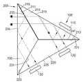
도 2를 참조하면, 본 발명의 제1실시예에 따른 조명유니트는 각각 서로 다른 파장의 광을 조사하는 복수의 광원유니트(100)와, 상기 광원유니트(100)에서 조명 된 광 각각이 동일 경로로 진행하도록 입사광을 합성하는 합성 프리즘(200)을 포함한다.Referring to FIG. 2, the lighting unit according to the first exemplary embodiment of the present invention includes a plurality of
상기 광원유니트(100)는 배치 위치 및 조사하는 광 파장 차이에 따라 제1 내지 제3광원유니트(110)(120)(130)로 구분된다. 이 제1 내지 제3광원유니트(110)(120)(130)는 서로 다른 파장의 제1 내지 제3광 예컨대, 녹, 청, 적색 파장의 광을 각각 조사한다.The
상기 합성 프리즘(200)은 삼각기둥형상으로서, 입사방향에 따라 광을 투과 또는 전반사시키는 외측면과 다른 두 삼각형 프리즘 각각과 결합되는 두 경계면을 각각 가지는 제1 내지 제3삼각형 프리즘(210)(220)(230)과, 상기 제1 내지 제3삼각형 프리즘(210)(220)(230) 사이의 적어도 어느 한 경계에 마련되어 입사광을 파장에 따라 선택적으로 투과 또는 반사시키는 색분리부를 포함한다.The
상기 제1삼각형 프리즘(210)은 제1 및 제2경계면(211)(213)과, 광의 입사방향에 따라 입사광을 투과 또는 반사시키는 제1외측면(215)을 가진다.The first
상기 제1광원유니트(110)는 상기 제1외측면(215)에 마주하게 배치되어 있다. 따라서, 상기 제1광원유니트(110)에서 직접 입사된 제1광은 상기 제1외측면(215)을 투과하여 상기 제2경계면(213) 쪽으로 향한다. 반면, 상기 제2경계면(213) 쪽에서 임계각 이상의 각도로 입사된 제1 및 제2광은 상기 제1외측면(215)에서 내부 전반사되어 상기 제1경계면(211) 쪽으로 향한 후, 후술하는 제3외측면(235)을 투과하여 진행한다.The first
여기서, 내부 전반사는 제1삼각형 프리즘(210)의 굴절률 값이 그 주변의 굴 절률 값보다 크고, 제1삼각형 프리즘(210) 내부에서 임계각 보다 큰 각도로 제1 및 제2광이 입사된 경우에 일어난다.Here, the total internal reflection when the first and second light is incident at an angle larger than the critical angle in the refractive index value of the first
상기 제2삼각형 프리즘(220)은 제3 및 제4경계면(221)(223)과, 입사광을 투과시키는 제2외측면(225)을 가진다. 여기서, 상기 제3경계면(221)은 상기 제1삼각형 프리즘(210)의 제2경계면(213)에 마주하게 배치된다.The second
그리고, 상기 제2외측면(225)에는 상기 제2 및 제3광원유니트(120)(130)가 마주하게 배치된다. 따라서, 상기 제2 및 제3광원유니트(120)(130)에서 조사된 제2 및 제3광은 상기 제2외측면(225)을 투과하여, 제2광은 상기 제3경계면(221) 쪽으로 향하고, 제3광은 상기 제4경계면(223) 쪽으로 향한다.The second and third
상기 제3삼각형 프리즘(230)은 제5 및 제6경계면(231)(233)과, 광의 입사방향에 따라 입사광을 투과 또는 반사시키는 제3외측면(235)을 가진다. 여기서, 상기 제5경계면(231)은 상기 제4경계면(223)에 마주하게 배치되고, 상기 제6경계면(233)은 상기 제1경계면(211)에 마주하게 배치된다. 따라서, 상기 제3광원유니트(130)에서 입사된 제3광은 상기 제3외측면(235)에서 전반사되어 상기 제6경계면(233) 쪽으로 향하고, 상기 제6경계면(233) 쪽에서 입사된 제1 내지 제3광은 상기 제3외측면(235)을 투과하여 진행한다.The third
여기서, 상기 제1 내지 제3삼각형 프리즘(210)(220)(230)은 서로 다른 위치에서 입사된 제1 내지 제3광이 동일한 경로로 향하도록 하기 위하여, 상호 동일한 형상 및 크기를 가지는 것이 바람직하다. 보다 바람직하게는 상기 제1삼각형 프리즘(210)은 제1경계면(211)과 제2경계면(213) 사이의 각이 120°이고, 제1경계면 (211)과 제1외측면(215) 사이의 각과 제2경계면(213)과 제1외측면(215) 사이의 각이 각각 30°인 이등변 삼각형상의 프리즘이다. 마찬가지로, 상기 제2 및 제3삼각형 프리즘(220)(230)도 제1삼각형 프리즘(210)과 같은 조건을 가지는 이등변 삼각형상의 프리즘이다.Here, the first to third
상기 색분리부는 상기 제2경계면(213)과 제3경계면(221) 사이, 제4경계면(223)과 제5경계면(231) 사이 및, 제6경계면(233)과 제1경계면(211) 사이 중 적어도 어느 한 곳에 배치된다. 본 실시예에 있어서, 상기 색분리부는 제2경계면(213)과 제3경계면(221) 사이 및, 제6경계면(233)과 상기 제1경계면(211) 사이에 각각 마련된 제1 및 제2다이크로익 필터(dichroic filter)(241)(245)를 포함한다.The color separation unit is between the
상기 제1다이크로익 필터(241)는 상기 제1광원유니트(110)에서 조사된 제1파장영역의 제1광은 반사시키고, 상기 제2광원유니트(120)에서 조사된 제2파장영역의 제2광은 투과시킨다.The first
예컨대, 녹색과 청색 사이의 소정 파장 예컨대 500nm 파장을 기준으로 긴 파장영역의 광은 반사시키고, 짧은 파장영역의 광은 투과시킨다. 따라서, 제1광이 녹색 파장영역의 광이고, 제2광이 청색 파장영역의 광인 경우, 제1광은 상기 제1다이크로익 필터(241)에서 반사되고, 제2광은 제1다이크로익 필터(241)를 투과하여 제1광과 동일한 경로로 진행한다.For example, light in a long wavelength region is reflected and light in a short wavelength region is transmitted based on a predetermined wavelength, for example, 500 nm, between green and blue. Accordingly, when the first light is light in the green wavelength region and the second light is light in the blue wavelength region, the first light is reflected by the first
상기 제2다이크로익 필터(245)는 제3파장영역 예컨대 적색 파장영역의 제3광은 반사시키고, 다른 파장영역의 상기 제1 및 제2광은 투과시킨다.The second
예컨대, 적색과 녹색 사이의 소정 파장 예컨대 565 nm 파장을 기준으로 긴 파장영역의 광은 반사시키고, 짧은 파장영역의 광은 투과시킨다. 따라서, 제1 및 제2광 각각이 녹색과 청색 파장영역의 광이고, 제3광이 적색 파장영역의 광인 경우, 제1 및 제2광은 상기 제2다이크로익 필터(245)를 투과하고, 제3광은 제1다이크로익 필터(245)에서 반사되어 상기 제1 및 제2광과 동일한 경로로 진행한다.For example, based on a predetermined wavelength between red and green, for example, a wavelength of 565 nm, light in a long wavelength region is reflected and light in a short wavelength region is transmitted. Therefore, when each of the first and second lights is light in the green and blue wavelength region, and the third light is light in the red wavelength region, the first and second light pass through the second
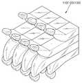
상기 제1 내지 제3광원유니트(110)(120)(130) 각각은 도 4 내지 도 6에 도시된 바와 같이, 적어도 하나 이상의 광모듈(140)로 구성된다.Each of the first to third
도면들을 참조하면, 상기 광모듈(140)은 반사면을 가지는 콜리메이터(150)와, 소정 파장의 광을 조사하는 광원(160)을 구비한다. 상기 콜리메이터(150)는 포물면 형상의 제1반사면(151)과, 사각형상의 단면을 가지는 글래스로드(glass rod)(155)를 포함한다. 광원(160)은 적어도 하나의 발광다이오드(LED), 레이저 다이오드 등으로 구성되는 소형 광원으로, 그 발광부분이 상기 제1반사면(151)의 초점(F) 및 그 주변에 위치된다. 상기 제1반사면(151)은 상기 글래스로드(155)의 일부를 포물면 형태로 가공하고, 그 외면에 반사코팅을 함에 의하여 형성된다. 또한, 상기 콜리메이터(150)는 상기 제1반사면(151)과 대면되는 위치의 상기 광원(160)에서 직접 조사된 광이 통과하는 영역(G)을 제외한 영역에 반사 코팅에 의하여 형성된 제2반사면(153)을 더 구비할 수 있다.Referring to the drawings, the
따라서, 상기 광원(160)에서 조사된 광 중 소정 방사각 범위 내의 광은 상기 제1반사면(151)에서 반사 된 후 평행광이 된다. 이 평행광은 글래스로드(155) 내부를 통과한 후 출광면(157)을 통하여 진행한다. 한편, 상기 광원(160)의 발광부분은 하나의 점을 이루는 것이 아니라 소정 면적을 가지므로, 이 발광부분 전체가 상기 제1반사면(151)의 초점 위치(F)에 배치될 수는 없다. 따라서, 상기 광원(160)에서 조사되고 상기 제1반사면(151)에서 반사된 광의 일부는 상기 제2반사면(153)으로 진행된다. 이때, 상기 제2반사면(153)은 입사된 광을 반사시켜 출광면(157) 쪽으로 향하도록 한다.Accordingly, light within a predetermined emission angle range among the light emitted from the
본 실시예에 따른 광모듈(140)은 광원(160)에서 조명된 광을 렌즈 대신 제1반사면(151)을 이용하여 콜리메이팅 시킴으로써, 렌즈를 사용시 야기되는 에텐듀(etendue) 등의 원리적 제약에 따른 효율이 저하되는 등의 문제를 근본적으로 해결할 수 있다.The
상기한 실시예에 있어서, 글래스로드(155)를 이용한 콜리메이터(150)에 대하여 설명하였지만, 본 발명은 이에 한정되는 것은 아니며, 글래스로드(155) 대신 속이 빈 광터널(미도시)의 일측에 포물 반사면을 형성하고, 그 내부를 반사 처리함으로써 반사면을 형성하는 것도 가능하다.In the above-described embodiment, the
또한, 본 발명에 따른 조명유니트는 상기 제1 내지 제3광원유니트(110)(120)(130)를 구성함에 있어서, 도 5에 도시된 바와 같이, 복수의 광모듈(140)을 구비하고, 이들을 어레이 형태로 배열할 수 있다. 이 경우, 제1 내지 제3원유니트(110)(120)(130)를 이루는 어레이 형태의 광모듈 각각은 적, 녹, 청색 파장의 광을 조명한다. 따라서, 제1 내지 제3광원유니트(110)(120)(130)를 동시 또는 순차로 구동하여, 광을 조사함에 의하여, 녹, 청, 적색 파장의 광을 조사함과 아울러, 이들의 조합으로 이루어진 풀 칼라의 광을 조명할 수 있다. 따라서, 후술하는 화상투사장치에 적용시, 칼라 구현을 위한 칼라휠(color wheel)장치 없이도, 칼라 광을 조명할 수 있다.In addition, the lighting unit according to the present invention comprises a plurality of
상기한 바와 같이, 구성된 본 발명의 제1실시예에 따른 조명유니트는 삼각 프리즘 구조의 합성 프리즘을 이용하여 제1 내지 제3광원유니트에서 조명된 광을 합성함으로써, 임계각 전반사원리를 이용한 광의 경로 변환이 용이하고, 종래의 트리크로익 프리즘 구조에 비하여 광학적 배치가 용이하다는 이점이 있다.As described above, the illumination unit according to the first embodiment of the present invention configured to synthesize the light illuminated in the first to third light source units using a synthetic prism of a triangular prism structure, thereby converting the path of light using the critical angle total reflection principle This has the advantage that it is easy and the optical arrangement is easy as compared with the conventional trichroic prism structure.
도 6을 참조하면, 본 발명의 제2실시예에 따른 조명유니트는 각각 서로 다른 파장의 광을 조사하는 복수의 광원유니트(100)와, 상기 광원유니트(100)에서 조명된 광 각각이 동일 경로로 진행하도록 입사광을 합성하는 합성 프리즘(200)을 포함한다.Referring to FIG. 6, the lighting unit according to the second exemplary embodiment of the present invention includes a plurality of
본 실시예는 제1실시예와 비교하여 볼 때, 합성 프리즘(200)의 제1 및 제3외측면(215)(235)에서의 전반사 특성을 고려하여, 제1 및 제2반사층(251)(255)을 더 구비한 것에 특징이 있다. 한편, 이를 제외한 다른 구성요소들의 구성 및 배치는 앞서 설명된 제1실시예에 따른 조명유니트와 실질상 동일하므로, 그 자세한 설명은 생략하기로 한다.Compared to the first embodiment, the present embodiment considers the total reflection characteristics of the first and third outer side surfaces 215 and 235 of the
상기 제1반사층(251)은 상기 제1외측면(215)의 일부에 전반사 코팅에 의하여 형성된 층으로, 제1다이크로익 필터(241)를 경유하여 입사된 제1 및 제2광을 전반사시킨다. 한편, 상기 제1반사층(251)은 제1광원유니트(110)에서 직접 조명된 제1광이 입사되는 부분에 대해서는 마련되어 있지 않아서, 이 제1다이크로익 필터(241) 방향으로 향하는 제1광의 진행에는 영향을 미치지 않는다.The
상기 제2반사층(255)은 상기 제3외측면(235)의 일부에 전반사 코팅에 의하여 형성된 층으로, 상기 제3광원유니트(130) 쪽에서 직접 입사된 제3광을 반사시킨다. 한편, 상기 제2다이크로익 필터(245)를 경유하여 입사된 제1 내지 제3광이 진행하는 경로에는 상기 제2반사층(255)이 배제되어 있어서, 그 광의 진행에 영향을 미치지 않는다.The
도 7을 참조하면, 본 발명의 제3실시예에 따른 조명유니트는 각각 서로 다른 파장의 광을 조사하는 복수의 광원유니트(300)와, 상기 광원유니트(300)에서 조명된 광 각각이 동일 경로로 진행하도록 입사광을 합성하는 합성 프리즘(400)을 포함한다.Referring to FIG. 7, the lighting unit according to the third exemplary embodiment of the present invention includes a plurality of
상기 광원유니트(300)는 배치 위치 및 조사하는 광의 파장 차이에 따라 제1 내지 제4광원유니트(310)(320)(330)(340)로 구분된다. 이 제1 내지 제4광원유니트(310)(320)(330)(340)는 서로 다른 파장의 제1 내지 제4광 예컨대, 녹, 청, 적, 노란색 파장의 광을 각각 조사한다. 이 제1 내지 제3광원유니트(310)(320)(330)(340) 각각의 구성은 도 4 내지 도 6을 참조하여 설명된 바와 같으므로, 그 자세한 설명은 생략한다.The
상기 합성 프리즘(400)은 삼각기둥형상으로서, 입사방향에 따라 광을 투과 또는 전반사시키는 외측면과 다른 두 삼각형 프리즘 각각과 결합되는 두 경계면을 각각 가지는 제1 내지 제3삼각형 프리즘(410)(420)(430)과, 상기 제1 내지 제3삼각형 프리즘(410)(420)(430) 사이의 적어도 어느 한 경계에 마련되어 입사광을 파장에 따라 선택적으로 투과 또는 반사시키는 색분리부를 포함한다.The
상기 제1삼각형 프리즘(410)은 제1 및 제2경계면(411)(413)과, 광의 입사방 향에 따라 입사광을 투과 또는 반사시키는 제1외측면(415)을 가진다. 상기 제2삼각형 프리즘(420)은 제3 및 제4경계면(421)(423)과, 입사광을 투과시키는 제2외측면(425)을 가진다. 그리고, 상기 제3삼각형 프리즘(430)은 제5 및 제6경계면(431)(433)과, 광의 입사방향에 따라 입사광을 투과 또는 반사시키는 제3외측면(435)을 가진다. 이 제1 내지 제3삼각형 프리즘(410)(420)(430) 각각의 배치 및 이에 대한 제1 내지 제3광원유니트(310)(320)(330)의 배치는 제1실시예에 따른 동일 부재명의 구성요소와 실질상 동일하다.The first
본 실시예에 있어서, 상기 색분리부는 제2경계면(413)과 제3경계면(421) 사이, 제6경계면(433)과 상기 제1경계면(411) 사이 및, 제4경계면(423)과 상기 제5경계면(431) 사이에 각각 마련된 제1 내지 제3다이크로익 필터(441)(445)(447)를 포함한다.In the present embodiment, the color separation unit is between the
여기서, 본 실시예에 따른 색분리부는 제3광원유니트(330)과 제4광원유니트(340) 각각에서 조명된 제3광과 제4광을 분리하기 위한 제3다이크로익 필터(447)를 더 구비한 것에 특징이 있다. 상기 제3다이크로익 필터(447)는 상기 제3광원유니트(430)에서 조사된 제3파장영역의 제3광은 투과시키고, 상기 제4광원유니트(440)에서 조사된 제4파장영역의 제4광은 투과시킨다.Here, the color separation unit according to the present embodiment uses a third
예컨대, 적색과 노란색 사이의 소정 파장 예컨대 600 nm 파장을 기준으로 긴 파장영역의 광은 투과시키고, 짧은 파장영역의 광은 반사시킨다. 따라서, 제3광이 적색 파장영역의 광이고, 제4광의 노란색 파장영역의 광인 경우, 제3광은 상기 제3다이크로익 필터(447)를 투과하고, 제4광은 반사되어, 서로 동일한 경로로 진행한 다.For example, based on a predetermined wavelength, for example, 600 nm wavelength between red and yellow, light in a long wavelength region is transmitted and light in a short wavelength region is reflected. Therefore, when the third light is light in the red wavelength region, and the light in the yellow wavelength region of the fourth light, the third light passes through the third
한편, 제1 및 제2다이크로익 필터(441)(445)는 제1실시예에 따른 동일 부재명의 구성요소와 실질상 동일한 역할을 수행하므로 그 자세한 설명을 생략하기로 한다. 여기서, 제2다이크로익 필터(445)는 제1 및 제2광은 투과시키고, 제3 및 제4광은 반사시켜 상호 동일 경로로 진행하도록 한다.Meanwhile, since the first and second
본 실시예에 있어서, 제4광은 노란색 파장의 광으로 한정되는 것은 아니며, 색범위를 넓힐 수 있는 범위 내에서 다양한 파장의 광으로 변경 가능하다. 예컨대, 마젠타나 시안 파장의 광을 조명하는 광원유니트를 구비하는 것도 가능하다. 아울러, 본 실시예에 있어서 제1 내지 제4광 각각이 녹, 청, 적, 노란색 파장의 광을 조명하는 것을 예로 들어 설명하였으나, 이에 한정되는 것은 아니다. 즉, 제1 내지 제3다이크로익 필터의 배치를 변경함에 의하여 다양한 변형 실시가 가능하다.In the present embodiment, the fourth light is not limited to light having a yellow wavelength, and may be changed to light having various wavelengths within a range capable of widening the color range. For example, it is also possible to provide a light source unit for illuminating light of magenta or cyan wavelength. In addition, in the present embodiment, each of the first to fourth lights illuminates light of green, blue, red, and yellow wavelengths as an example, but is not limited thereto. That is, various modifications can be made by changing the arrangement of the first to third dichroic filters.
상기한 바와 같이, 구성된 본 발명의 제3실시예에 따른 조명유니트는 삼각 프리즘 구조의 합성 프리즘을 이용하여 제1 내지 제4광원유니트에서 조명된 광을 합성함으로써, 임계각 전반사원리를 이용한 광의 경로 변환이 용이하고, 종래의 트리크로익 프리즘 구조에 비하여 광학적 배치가 용이하다는 이점이 있다. 또한, 4색의 조합에 의하여 화상을 구현함으로써, 표현 가능한 색 범위가 넓어지는 이점이 있다.As described above, the lighting unit according to the third embodiment of the present invention is configured to synthesize the light illuminated in the first to fourth light source units using a synthetic prism having a triangular prism structure, thereby converting the path of light using the critical angle total reflection principle. This has the advantage that it is easy and the optical arrangement is easy as compared with the conventional trichroic prism structure. In addition, by implementing the image by a combination of four colors, there is an advantage that the range of colors that can be expressed.
도 8을 참조하면, 본 발명의 제4실시예에 따른 조명유니트는 각각 서로 다른 파장의 광을 조사하는 복수의 광원유니트(300)와, 상기 광원유니트(300)에서 조명된 광 각각이 동일 경로로 진행하도록 입사광을 합성하는 합성 프리즘(400)을 포함 한다.Referring to FIG. 8, the lighting unit according to the fourth exemplary embodiment of the present invention includes a plurality of
본 실시예는 제3실시예와 비교하여 볼 때, 합성 프리즘(400)의 제1 및 제3외측면(415)(435)에서의 전반사 특성을 고려하여, 제1 및 제2반사층(451)(455)을 더 구비한 것에 특징이 있다. 한편, 이를 제외한 다른 구성요소들의 구성 및 배치는 앞서 설명된 제3실시예에 따른 조명유니트와 실질상 동일하므로, 그 자세한 설명은 생략하기로 한다.Compared to the third embodiment, the present embodiment considers the total reflection characteristics of the first and third
상기 제1반사층(451)은 상기 제1외측면(415)의 일부에 전반사 코팅에 의하여 형성된 층으로, 제1다이크로익 필터(441)를 경유하여 입사된 제1 및 제2광을 전반사시킨다. 한편, 상기 제1반사층(451)은 제1광원유니트(310)에서 직접 조명된 제1광이 입사되는 부분에 대해서는 마련되어 있지 않아서, 이 제1다이크로익 필터(441) 방향으로 향하는 제1광의 진행에는 영향을 미치지 않는다.The
상기 제2반사층(455)은 상기 제3외측면(435)의 일부에 전반사 코팅에 의하여 형성된 층으로, 상기 제3다이크로익 필터(447)를 경유하여 입사된 제3 및 제4광을 반사시킨다. 한편, 상기 제2다이크로익 필터(445)를 경유하여 입사된 제1 내지 제4광이 진행하는 경로에는 상기 제2반사층(455)이 배제되어 있어서, 그 광의 진행에 영향을 미치지 않는다.The second reflection layer 455 is a layer formed by a total reflection coating on a portion of the third
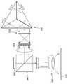
도 9를 참조하면, 본 발명의 제1실시예에 따른 화상투사장치는 조명유니트(500)와, 이 조명유니트(500) 쪽에서 입사된 광으로부터 입력된 영상신호에 대응되는 화상을 형성하는 화상형성소자(550)와, 상기 화상형성소자(550)에서 형성된 화상을 스크린(570)에 확대 투사시키는 투사렌즈유니트(560)를 포함한다.Referring to FIG. 9, an image projecting device according to a first embodiment of the present invention forms an image corresponding to an
상기 조명유니트(500)는 복수의 광원유니트와, 이 광원유니트에서 조사된 복수의 광을 합성하는 합성프리즘을 포함하여, 서로 다른 위치에 배치된 광원유니트에서 조사된 광을 합성하여 조명하는 것으로, 도 2 내지 도 8을 참조하여 설명된 본 발명의 제1 내지 제4실시예에 따른 조명유니트의 구성과 실질상 동일하므로, 그 자세한 설명은 생략하기로 한다. 한편, 조명유니트(500)를 구성하는 복수의 광원유니트는 순차적으로 온/오프 구동되면서, 녹색, 청색, 적색 파장의 3색광 또는 녹색, 청색, 적색, 노란색(또는 마젠타나 시안 칼라)의 광을 순차적으로 조사한다. 따라서, 1패널 구조의 화상형성소자를 이용한 화상투사장치를 구성함에 있어서, 칼라 화상 구현에 이용되는 칼라휠(미도시) 등의 구성을 상기 조명유니트(500)가 대체할 수 있다.The
상기 화상형성소자(550)는 입사된 균일한 조명광을 화소단위로 선택적으로 반사시켜 화상을 형성한다. 이 화상형성소자(550)는 반사형 액정표시소자, 투과형 액정표시소자 또는 DMD(디지털 마이크로미러 디바이스) 등으로 구성된다. 여기서, 반사형 또는 투과형 액정표시소자는 입사광의 편광특성을 이용하여 화상을 구현하는 반면, DMD의 경우는 편광특성을 이용하지 않는다. 그러므로, 화상형성소자(550)로서 DMD를 채용한 경우는 별도의 편광변환소자 내지 폴라라이저의 채용이 불필요하다.The
한편, 본 실시예는 DMD를 화상형성소자(550)로서 채용한 것을 예로 들어 나타낸 것이다. 상기 DMD는 독립적으로 구동되는 2차원 배열 구조의 마이크로미러 어레이를 포함하는 것으로, 입력된 화상신호에 따라 각 화소별 반사광의 각도를 독립 적으로 설정함에 의하여 화상을 형성한다. 이 경우, 입사광의 진행 경로를 변환하기 위한 수단으로서, 상기 조명유니트(500), 상기 화상형성소자(550) 및 상기 투사렌즈유니트(560) 사이에 배치되는 빔스프리터(540)를 더 구비하는 것이 바람직하다. 상기 빔스프리터(540)는 상기 조명유니트(500) 쪽에서 입사된 빔은 상기 화상형성소자(550) 방향으로 향하도록 하고, 상기 화상형성소자(550) 쪽에서 입사된 빔은 스크린(570) 방향으로 향하도록 입사빔의 경로를 변환한다. 이 빔스프리터(540)는 임계각 전반사 특성을 이용하여 빔의 경로를 변환하는 구조의 임계각 프리즘인 것이 바람직하다.In the present embodiment, the DMD is employed as the
상기 투사렌즈유니트(560)는 상기 빔스프리터(540)에 마주하게 배치되어, 상기 화상형성소자(550)에서 형성되고, 상기 빔스프리터(540)를 경유하여 입사된 화상을 확대하여 스크린(570) 쪽으로 투사시킨다.The
또한, 본 실시예에 따른 화상투사장치는 조명유니트(500)와 상기 빔스프리터(540) 사이에 배치되어, 상기 조명유니트(500)로부터 입사된 광이 균일광이 되도록 하는 광인터그레이터(520)를 더 포함하는 것이 바람직하다. 상기 광인터그레이터(520)는 내부에 입사된 광을 전반사시키면서 전달하는 직육면체 구조의 글래스 로드로 구성될 수 있다. 이 경우, 상기 광원유니트(500)와 상기 글래스 로드 사이에는 입사광을 집속시키는 콘덴싱렌즈 유니트(510)이 더 구비된 것이 바람직하다. 이 콘덴싱렌즈 유니트(510)는 1매 이상의 렌즈로 구성되는 것으로, 입사된 평행광을 집속시켜 상기 글래스 로드에 입사되도록 한다.In addition, the image projecting device according to the present embodiment is disposed between the
또한, 본 실시예에 따른 화상투사장치는 상기 글래스 로드와 상기 빔스프리 터(540) 사이에 배치되는 릴레이렌즈 유니트(530)를 더 구비하는 것이 바람직하다. 이 릴레이렌즈 유니트(530)는 상기 글래스 로드에서 출력된 균일광을 결상위치인 DMD로 릴레이하는 1매 이상의 렌즈로 구성된다.In addition, it is preferable to further include a
도 10을 참조하면, 본 발명의 제2실시예에 따른 화상투사장치는 조명유니트(600)와, 이 조명유니트(600) 쪽에서 입사된 광으로부터 입력된 영상신호에 대응되는 화상을 형성하는 화상형성소자(650)와, 상기 화상형성소자(650)에서 형성된 화상을 스크린(670)에 확대 투사시키는 투사렌즈유니트(660)를 포함한다.Referring to FIG. 10, an image projecting device according to a second embodiment of the present invention forms an image corresponding to an
상기 조명유니트(600)는 도 2 내지 도 8을 참조하여 설명된 본 발명의 제1 내지 제4실시예에 따른 조명유니트의 구성과 실질상 동일하므로, 그 자세한 설명은 생략하기로 한다.Since the
상기 화상형성소자(650)는 입사된 균일한 조명광을 화소단위로 선택적으로 반사시켜 화상을 형성한다. 본 실시예는 입사광의 편광특성을 이용하여 화상을 구현하는 반사형 액정표시소자를 화상형성소자(650)로서 채용한 것을 예로 들어 나타낸 것이다.The
이 경우, 입사광의 진행 경로를 변환하기 위한 수단으로서, 상기 조명유니트(600), 상기 화상형성소자(650) 및 상기 투사렌즈유니트(660) 사이에 배치되는 편광빔스프리터(640)를 더 구비하는 것이 바람직하다. 상기 편광빔스프리터(640)는 상기 조명유니트(600) 쪽에서 입사된 빔은 상기 화상형성소자(650) 방향으로 향하도록 하고, 상기 화상형성소자(650) 쪽에서 입사된 빔은 스크린(670) 방향으로 향하도록 입사빔의 경로를 변환한다. 이를 위하여, 상기 조명유니트(600)와 상기 편 광빔스프리터(640) 사이에 배치되어, 입사광의 편광방향을 변환하여 특정 편광의 광이 상기 편광빔스프리터(640) 방향으로 향하도록 하는 편광변환소자(630)를 더 구비하는 것이 바람직하다. 이 편광변환소자(630)는 복수의 소형 편광빔스프리터와, 1/4파장판을 포함하여 구성되는 것으로, 입사된 무편광의 광 대부분을 특정 편광의 광으로 바꾸어준다. 이 편광변환소자(630) 자체의 구성은 잘 알려져 있으므로 그 자세한 설명은 생략하기로 한다.In this case, as a means for converting the traveling path of the incident light, further comprising a
또한, 본 실시예에 따른 화상투사장치는 상기 조명유니트(600)로부터 입사된 광이 균일광이 되도록 하는 광인터그레이터(620)를 더 포함하는 것이 바람직하다. 상기 광인터그레이터(620)는 서로 이웃되게 배열된 볼록 형상 또는 실린드리컬 형상의 복수의 렌즈셀을 각각 포함하는 적어도 1매의 렌즈를 포함하는 플라이-아이 렌즈어레이로 구성될 수 있다.In addition, the image projection value according to the present embodiment preferably further includes a
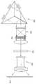
도 11을 참조하면, 본 발명의 제3실시예에 따른 화상투사장치는 조명유니트(700)와, 이 조명유니트(700) 쪽에서 입사된 광으로부터 입력된 영상신호에 대응되는 화상을 형성하는 화상형성소자(740)와, 상기 화상형성소자(740)에서 형성된 화상을 스크린(770)에 확대 투사시키는 투사렌즈유니트(760)를 포함한다.Referring to FIG. 11, an image projection apparatus according to a third embodiment of the present invention forms an image corresponding to an
상기 조명유니트(700)는 도 2 내지 도 8을 참조하여 설명된 본 발명의 제1 내지 제4실시예에 따른 조명유니트의 구성과 실질상 동일하므로, 그 자세한 설명은 생략하기로 한다.Since the
상기 화상형성소자(740)는 입사된 균일한 조명광을 화소단위로 선택적으로 반사시켜 화상을 형성한다. 본 실시예는 입사광의 편광특성을 이용하여 화상을 구 현하는 투과형 액정표시소자를 화상형성소자(740)로서 채용한 것을 예로 들어 나타낸 것이다. 이 경우, 입사광의 진행 경로를 변환하기 위한 수단이 불필요하므로, 앞서 설명된 제1 및 제2실시예에 따른 화상투사장치와는 달리 빔스프리터가 불필요하다는 이점이 있다.The
한편, 상기한 투과형 액정표시소자는 편광특성을 이용하여 화상을 형성하므로, 이를 위하여 상기 조명유니트(700)와 상기 화상형성소자(740) 사이에 편광변환소자(730)를 더 구비한 것이 바람직하다. 또한, 본 실시예에 따른 화상투사장치는 상기 조명유니트(700)로부터 입사된 광이 균일광이 되도록 하는 광인터그레이터(720)를 더 포함하는 것이 바람직하다. 상기 광인터그레이터(720)는 서로 이웃되게 배열된 볼록 형상 또는 실린드리컬 형상의 복수의 렌즈셀을 각각 포함하는 적어도 1매의 렌즈를 포함하는 플라이-아이 렌즈어레이로 구성될 수 있다.On the other hand, since the transmissive liquid crystal display device forms an image using polarization characteristics, it is preferable to further include a
상기한 바와 같이 구성된 본 발명에 따른 조명유니트는 삼각 프리즘 구조의 합성 프리즘을 이용하여 제1 내지 제3광원유니트에서 조명된 광을 합성함으로써, 임계각 전반사원리를 이용한 광의 경로 변환이 용이하고, 종래의 트리크로익 프리즘 구조에 비하여 광학적 배치가 용이하다는 이점이 있다. 또한, 광원유니트를 구성함에 있어서, 렌즈 대신 반사면을 이용하여 콜리메이팅 시킴으로써, 렌즈를 사용시 야기되는 에텐듀(etendue) 등의 원리적 제약에 따른 효율이 저하되는 등의 문제를 근본적으로 해결할 수 있다. 그리고, 제4광을 조명하는 별도의 광원유니트를 더 구비하는 경우, 표현하고자 하는 색 범위를 넓힐 수 있어서, 다양한 칼라의 광을 조명할 수 있다는 이점이 있다.The lighting unit according to the present invention configured as described above is easy to convert the path of light using the critical angle total reflection principle by synthesizing the light illuminated from the first to third light source units using a synthetic prism of a triangular prism structure, Compared to the tricroic prism structure, there is an advantage in that the optical arrangement is easy. In addition, in constructing the light source unit, by collimating using a reflective surface instead of a lens, problems such as deterioration in efficiency due to principle constraints such as etendue caused when using the lens can be fundamentally solved. . In addition, in the case of further comprising a separate light source unit for illuminating the fourth light, it is possible to widen the color range to be expressed, there is an advantage that it is possible to illuminate light of various colors.
또한, 본 발명에 따른 화상투사장치는 상기한 조명유니트를 채용함으로써, 그 구성을 콤팩트화 할 수 있고, 서로 다른 파장의 광을 조명하는 제1 내지 제3광원유니트를 이용하여 칼라 광을 조명함으로써, 별도의 칼라 휠 장치 없이도, 칼라 화상을 구현할 수 있다는 이점이 있다.In addition, the image projecting device according to the present invention can be compactized by employing the above-described lighting unit, and by illuminating color light using the first to third light source units illuminating light of different wavelengths. There is an advantage in that a color image can be realized without a separate color wheel device.
상기한 실시예들은 예시적인 것에 불과한 것으로, 당해 기술분야의 통상을 지식을 가진자라면 이로부터 다양한 변형 및 균등한 타 실시예가 가능하다. 따라서, 본 발명의 진정한 기술적 보호범위는 하기의 특허청구범위에 기재된 발명의 기술적 사상에 의해 정해져야만 할 것이다.The above embodiments are merely exemplary, and various modifications and equivalent other embodiments are possible from those skilled in the art. Therefore, the true technical protection scope of the present invention will be defined by the technical spirit of the invention described in the claims below.
Claims (21)
Translated fromKoreanPriority Applications (6)
| Application Number | Priority Date | Filing Date | Title |
|---|---|---|---|
| KR1020040061095AKR100619043B1 (en) | 2004-08-03 | 2004-08-03 | Illuminating unit and projection type image display apparatus employing the same |
| US11/154,671US7568805B2 (en) | 2004-08-03 | 2005-06-17 | Illumination unit and image projecting apparatus employing the same |
| JP2005221618AJP4471903B2 (en) | 2004-08-03 | 2005-07-29 | Illumination unit and image projection apparatus employing the same |
| DE602005007811TDE602005007811D1 (en) | 2004-08-03 | 2005-07-29 | Illumination unit for an image projection device |
| EP05107052AEP1626585B1 (en) | 2004-08-03 | 2005-07-29 | Illumination unit for an image projecting apparatus |
| CN2005100889191ACN100406960C (en) | 2004-08-03 | 2005-08-01 | Lighting unit and image projection device using the same |
Applications Claiming Priority (1)
| Application Number | Priority Date | Filing Date | Title |
|---|---|---|---|
| KR1020040061095AKR100619043B1 (en) | 2004-08-03 | 2004-08-03 | Illuminating unit and projection type image display apparatus employing the same |
Publications (2)
| Publication Number | Publication Date |
|---|---|
| KR20060012413A KR20060012413A (en) | 2006-02-08 |
| KR100619043B1true KR100619043B1 (en) | 2006-09-01 |
Family
ID=36076805
Family Applications (1)
| Application Number | Title | Priority Date | Filing Date |
|---|---|---|---|
| KR1020040061095AExpired - Fee RelatedKR100619043B1 (en) | 2004-08-03 | 2004-08-03 | Illuminating unit and projection type image display apparatus employing the same |
Country Status (6)
| Country | Link |
|---|---|
| US (1) | US7568805B2 (en) |
| EP (1) | EP1626585B1 (en) |
| JP (1) | JP4471903B2 (en) |
| KR (1) | KR100619043B1 (en) |
| CN (1) | CN100406960C (en) |
| DE (1) | DE602005007811D1 (en) |
Families Citing this family (27)
| Publication number | Priority date | Publication date | Assignee | Title |
|---|---|---|---|---|
| JP2005140847A (en)* | 2003-11-04 | 2005-06-02 | Tamron Co Ltd | Led light source projector optical system and led light source projector |
| KR100636164B1 (en)* | 2004-08-27 | 2006-10-18 | 삼성전자주식회사 | Color Prism and Image Projection Apparatus |
| WO2007015389A1 (en)* | 2005-08-04 | 2007-02-08 | Matsushita Electric Industrial Co., Ltd. | Illuminator and projection display employing it |
| TWI347452B (en)* | 2006-04-14 | 2011-08-21 | Delta Electronics Inc | Beam combiner and projecting system having the same |
| JP2008203467A (en)* | 2007-02-19 | 2008-09-04 | Sanyo Electric Co Ltd | Optical element, illumination device and projection type image display apparatus |
| KR100867922B1 (en)* | 2007-10-09 | 2008-11-10 | 삼성에스디아이 주식회사 | Battery pack |
| JP5199697B2 (en)* | 2008-02-27 | 2013-05-15 | 三洋電機株式会社 | Illumination device and projection display device |
| TWI385415B (en)* | 2008-07-10 | 2013-02-11 | Delta Electronics Inc | Light integration device for an illumination system and illumination system using the same |
| KR101004532B1 (en)* | 2008-07-18 | 2010-12-31 | 재단법인 한국조명연구원 | Lighting device using LED lamp |
| JP5315845B2 (en)* | 2008-08-07 | 2013-10-16 | 株式会社リコー | Illumination device and projection-type image display device |
| KR101039885B1 (en)* | 2009-06-22 | 2011-06-09 | 엘지이노텍 주식회사 | Color wheel light emitting unit and projection system using the same |
| JP5468399B2 (en)* | 2010-01-26 | 2014-04-09 | 三菱電機株式会社 | Projection display |
| US8376551B2 (en)* | 2010-02-25 | 2013-02-19 | Corning Incorporated | Illumination system for laser projection |
| KR101657216B1 (en)* | 2010-03-02 | 2016-09-19 | 삼성디스플레이 주식회사 | Touch panel and touch position detection method of touch panel |
| CN102375314B (en)* | 2010-08-09 | 2013-12-04 | 台达电子工业股份有限公司 | Light source system and its applicable projector |
| CN102768459A (en)* | 2012-07-12 | 2012-11-07 | 芜湖雅图数字视频技术有限公司 | Double-lamp illumination device and projection equipment |
| JP2014215480A (en)* | 2013-04-26 | 2014-11-17 | 株式会社日立エルジーデータストレージ | Optical unit and projection type display device |
| JP5942041B2 (en)* | 2013-08-29 | 2016-06-29 | 富士フイルム株式会社 | Color separation optical system and imaging apparatus |
| CN104714358A (en)* | 2015-01-06 | 2015-06-17 | 杨军 | Projector illumination module easy to machine and produce |
| EP3236308B1 (en)* | 2016-04-19 | 2018-08-15 | LIMO GmbH | Laser device |
| KR102698248B1 (en)* | 2018-08-10 | 2024-08-23 | 삼성디스플레이 주식회사 | Display panel inspection equipment |
| US10788308B2 (en)* | 2018-09-21 | 2020-09-29 | Apple Inc. | Particulate matter sensors for portable electronic devices |
| KR20220018107A (en)* | 2020-08-05 | 2022-02-15 | 삼성디스플레이 주식회사 | Display device |
| US11867920B2 (en) | 2021-01-08 | 2024-01-09 | Sintai Optical (Shenzhen) Co., Ltd. | Beam splitting and combining device and electronic device |
| CN114879375B (en)* | 2021-02-05 | 2024-01-19 | 信泰光学(深圳)有限公司 | Light splitting and combining device and electronic equipment |
| CN117471832A (en)* | 2022-07-19 | 2024-01-30 | 中强光电股份有限公司 | Lighting systems and projection devices |
| CN119126473B (en)* | 2024-11-13 | 2025-01-28 | 福州弘丰光电科技有限公司 | Projection laser module |
Citations (5)
| Publication number | Priority date | Publication date | Assignee | Title |
|---|---|---|---|---|
| KR19990043696A (en)* | 1997-11-29 | 1999-06-15 | 전주범 | Projection type image display device |
| JP2000321667A (en)* | 2000-01-01 | 2000-11-24 | Seiko Epson Corp | Projection display device |
| JP2002244211A (en)* | 2001-02-22 | 2002-08-30 | Ricoh Co Ltd | Image projection device |
| US20020181117A1 (en)* | 2001-05-30 | 2002-12-05 | Delta Electronic, Inc. | Color separation prism assembly compensated for contrast enhancement and implemented as reflective imager |
| JP2004070017A (en)* | 2002-08-07 | 2004-03-04 | Mitsubishi Electric Corp | Illumination optical system structure of projection device and projection device |
Family Cites Families (14)
| Publication number | Priority date | Publication date | Assignee | Title |
|---|---|---|---|---|
| JP2505758B2 (en) | 1986-08-04 | 1996-06-12 | キヤノン株式会社 | Video projection equipment |
| US5619284A (en) | 1995-01-17 | 1997-04-08 | Philips Electronics North America Corporation | Beam combiner for LCD projector utilizing a penta-prism |
| KR19990055244A (en) | 1997-12-27 | 1999-07-15 | 전주범 | Projection type image display device |
| KR100792603B1 (en) | 1998-06-05 | 2008-01-09 | 세이코 엡슨 가부시키가이샤 | Light source device and display device |
| US6323893B1 (en)* | 1999-10-27 | 2001-11-27 | Tidenet, Inc. | Portable conference center |
| TW439050B (en) | 2000-07-05 | 2001-06-07 | Ho Lu | Optical projection system using reflective liquid crystal panel |
| US6523977B2 (en)* | 2001-02-20 | 2003-02-25 | Prokia Technology Co., Ltd. | Illuminating apparatus including a plurality of light sources that generate primary color light components |
| TW571119B (en)* | 2001-12-20 | 2004-01-11 | Delta Electronics Inc | Image projection device with integrated semiconductor light emitting element light source |
| CN2549486Y (en) | 2002-06-04 | 2003-05-07 | 邵剑心 | Small rear projection color display devices |
| JP2004070018A (en) | 2002-08-07 | 2004-03-04 | Mitsubishi Electric Corp | Illumination optical system structure of projection device and projection device |
| JP4153776B2 (en) | 2002-11-07 | 2008-09-24 | 三菱電機株式会社 | Planar light source device and liquid crystal display device using the same |
| EP1631855B1 (en) | 2003-06-10 | 2015-08-05 | Samsung Electronics Co., Ltd. | Compact led module and projection display adopting the same |
| US7101063B2 (en)* | 2004-02-05 | 2006-09-05 | Hewlett-Packard Development Company, L.P. | Systems and methods for integrating light |
| KR101109584B1 (en)* | 2004-11-27 | 2012-01-31 | 삼성전자주식회사 | Lighting unit and image projector using the same |
- 2004
- 2004-08-03KRKR1020040061095Apatent/KR100619043B1/ennot_activeExpired - Fee Related
- 2005
- 2005-06-17USUS11/154,671patent/US7568805B2/ennot_activeExpired - Fee Related
- 2005-07-29DEDE602005007811Tpatent/DE602005007811D1/ennot_activeExpired - Fee Related
- 2005-07-29JPJP2005221618Apatent/JP4471903B2/ennot_activeExpired - Fee Related
- 2005-07-29EPEP05107052Apatent/EP1626585B1/ennot_activeExpired - Lifetime
- 2005-08-01CNCN2005100889191Apatent/CN100406960C/ennot_activeExpired - Fee Related
Patent Citations (5)
| Publication number | Priority date | Publication date | Assignee | Title |
|---|---|---|---|---|
| KR19990043696A (en)* | 1997-11-29 | 1999-06-15 | 전주범 | Projection type image display device |
| JP2000321667A (en)* | 2000-01-01 | 2000-11-24 | Seiko Epson Corp | Projection display device |
| JP2002244211A (en)* | 2001-02-22 | 2002-08-30 | Ricoh Co Ltd | Image projection device |
| US20020181117A1 (en)* | 2001-05-30 | 2002-12-05 | Delta Electronic, Inc. | Color separation prism assembly compensated for contrast enhancement and implemented as reflective imager |
| JP2004070017A (en)* | 2002-08-07 | 2004-03-04 | Mitsubishi Electric Corp | Illumination optical system structure of projection device and projection device |
Also Published As
| Publication number | Publication date |
|---|---|
| JP4471903B2 (en) | 2010-06-02 |
| KR20060012413A (en) | 2006-02-08 |
| CN100406960C (en) | 2008-07-30 |
| EP1626585B1 (en) | 2008-07-02 |
| DE602005007811D1 (en) | 2008-08-14 |
| US20060028816A1 (en) | 2006-02-09 |
| CN1734313A (en) | 2006-02-15 |
| JP2006048044A (en) | 2006-02-16 |
| EP1626585A1 (en) | 2006-02-15 |
| US7568805B2 (en) | 2009-08-04 |
Similar Documents
| Publication | Publication Date | Title |
|---|---|---|
| KR100619043B1 (en) | Illuminating unit and projection type image display apparatus employing the same | |
| KR100694068B1 (en) | Lighting unit and image projector using the same | |
| KR101109584B1 (en) | Lighting unit and image projector using the same | |
| US7455410B2 (en) | Illuminating apparatus and projector | |
| US8376551B2 (en) | Illumination system for laser projection | |
| JP3845637B2 (en) | Color illumination apparatus and image projection apparatus using the same | |
| US9016865B2 (en) | Illumination device and projection type display device using the same | |
| KR20050002791A (en) | Illuminating optical system, image display unit and method of illuminating space modulation element | |
| JP2012155342A (en) | Etendue efficient combination of multiple light sources | |
| KR20060040582A (en) | Projection engine with light pipe | |
| US9638988B2 (en) | Light multiplexer with color combining element | |
| JP4183663B2 (en) | Illumination device and projection display device | |
| KR100597820B1 (en) | Display device with optical device and optical device | |
| KR100636164B1 (en) | Color Prism and Image Projection Apparatus | |
| US6705731B2 (en) | Projection type display apparatus | |
| KR100667759B1 (en) | Lighting unit and image projector using the same | |
| KR100634001B1 (en) | Prism with light emitting diode |
Legal Events
| Date | Code | Title | Description |
|---|---|---|---|
| A201 | Request for examination | ||
| PA0109 | Patent application | St.27 status event code:A-0-1-A10-A12-nap-PA0109 | |
| PA0201 | Request for examination | St.27 status event code:A-1-2-D10-D11-exm-PA0201 | |
| R17-X000 | Change to representative recorded | St.27 status event code:A-3-3-R10-R17-oth-X000 | |
| PN2301 | Change of applicant | St.27 status event code:A-3-3-R10-R13-asn-PN2301 St.27 status event code:A-3-3-R10-R11-asn-PN2301 | |
| PN2301 | Change of applicant | St.27 status event code:A-3-3-R10-R13-asn-PN2301 St.27 status event code:A-3-3-R10-R11-asn-PN2301 | |
| D13-X000 | Search requested | St.27 status event code:A-1-2-D10-D13-srh-X000 | |
| D14-X000 | Search report completed | St.27 status event code:A-1-2-D10-D14-srh-X000 | |
| PG1501 | Laying open of application | St.27 status event code:A-1-1-Q10-Q12-nap-PG1501 | |
| E902 | Notification of reason for refusal | ||
| PE0902 | Notice of grounds for rejection | St.27 status event code:A-1-2-D10-D21-exm-PE0902 | |
| P11-X000 | Amendment of application requested | St.27 status event code:A-2-2-P10-P11-nap-X000 | |
| P13-X000 | Application amended | St.27 status event code:A-2-2-P10-P13-nap-X000 | |
| E701 | Decision to grant or registration of patent right | ||
| PE0701 | Decision of registration | St.27 status event code:A-1-2-D10-D22-exm-PE0701 | |
| GRNT | Written decision to grant | ||
| PR0701 | Registration of establishment | St.27 status event code:A-2-4-F10-F11-exm-PR0701 | |
| PR1002 | Payment of registration fee | St.27 status event code:A-2-2-U10-U11-oth-PR1002 Fee payment year number:1 | |
| PG1601 | Publication of registration | St.27 status event code:A-4-4-Q10-Q13-nap-PG1601 | |
| PR1001 | Payment of annual fee | St.27 status event code:A-4-4-U10-U11-oth-PR1001 Fee payment year number:4 | |
| PR1001 | Payment of annual fee | St.27 status event code:A-4-4-U10-U11-oth-PR1001 Fee payment year number:5 | |
| PR1001 | Payment of annual fee | St.27 status event code:A-4-4-U10-U11-oth-PR1001 Fee payment year number:6 | |
| R18-X000 | Changes to party contact information recorded | St.27 status event code:A-5-5-R10-R18-oth-X000 | |
| FPAY | Annual fee payment | Payment date:20120730 Year of fee payment:7 | |
| PR1001 | Payment of annual fee | St.27 status event code:A-4-4-U10-U11-oth-PR1001 Fee payment year number:7 | |
| FPAY | Annual fee payment | Payment date:20130730 Year of fee payment:8 | |
| PR1001 | Payment of annual fee | St.27 status event code:A-4-4-U10-U11-oth-PR1001 Fee payment year number:8 | |
| LAPS | Lapse due to unpaid annual fee | ||
| PC1903 | Unpaid annual fee | St.27 status event code:A-4-4-U10-U13-oth-PC1903 Not in force date:20140826 Payment event data comment text:Termination Category : DEFAULT_OF_REGISTRATION_FEE | |
| PC1903 | Unpaid annual fee | St.27 status event code:N-4-6-H10-H13-oth-PC1903 Ip right cessation event data comment text:Termination Category : DEFAULT_OF_REGISTRATION_FEE Not in force date:20140826 |