KR100617504B1 - Conveying device - Google Patents
Conveying deviceDownload PDFInfo
- Publication number
- KR100617504B1 KR100617504B1KR1020017006186AKR20017006186AKR100617504B1KR 100617504 B1KR100617504 B1KR 100617504B1KR 1020017006186 AKR1020017006186 AKR 1020017006186AKR 20017006186 AKR20017006186 AKR 20017006186AKR 100617504 B1KR100617504 B1KR 100617504B1
- Authority
- KR
- South Korea
- Prior art keywords
- arm
- link
- shaft
- joint
- support
- Prior art date
- Legal status (The legal status is an assumption and is not a legal conclusion. Google has not performed a legal analysis and makes no representation as to the accuracy of the status listed.)
- Expired - Fee Related
Links
Images


Classifications
- H—ELECTRICITY
- H01—ELECTRIC ELEMENTS
- H01L—SEMICONDUCTOR DEVICES NOT COVERED BY CLASS H10
- H01L21/00—Processes or apparatus adapted for the manufacture or treatment of semiconductor or solid state devices or of parts thereof
- H01L21/67—Apparatus specially adapted for handling semiconductor or electric solid state devices during manufacture or treatment thereof; Apparatus specially adapted for handling wafers during manufacture or treatment of semiconductor or electric solid state devices or components ; Apparatus not specifically provided for elsewhere
- H01L21/68—Apparatus specially adapted for handling semiconductor or electric solid state devices during manufacture or treatment thereof; Apparatus specially adapted for handling wafers during manufacture or treatment of semiconductor or electric solid state devices or components ; Apparatus not specifically provided for elsewhere for positioning, orientation or alignment
- H—ELECTRICITY
- H01—ELECTRIC ELEMENTS
- H01L—SEMICONDUCTOR DEVICES NOT COVERED BY CLASS H10
- H01L21/00—Processes or apparatus adapted for the manufacture or treatment of semiconductor or solid state devices or of parts thereof
- H01L21/67—Apparatus specially adapted for handling semiconductor or electric solid state devices during manufacture or treatment thereof; Apparatus specially adapted for handling wafers during manufacture or treatment of semiconductor or electric solid state devices or components ; Apparatus not specifically provided for elsewhere
- H01L21/683—Apparatus specially adapted for handling semiconductor or electric solid state devices during manufacture or treatment thereof; Apparatus specially adapted for handling wafers during manufacture or treatment of semiconductor or electric solid state devices or components ; Apparatus not specifically provided for elsewhere for supporting or gripping
- H01L21/687—Apparatus specially adapted for handling semiconductor or electric solid state devices during manufacture or treatment thereof; Apparatus specially adapted for handling wafers during manufacture or treatment of semiconductor or electric solid state devices or components ; Apparatus not specifically provided for elsewhere for supporting or gripping using mechanical means, e.g. chucks, clamps or pinches
- B—PERFORMING OPERATIONS; TRANSPORTING
- B25—HAND TOOLS; PORTABLE POWER-DRIVEN TOOLS; MANIPULATORS
- B25J—MANIPULATORS; CHAMBERS PROVIDED WITH MANIPULATION DEVICES
- B25J9/00—Programme-controlled manipulators
- B25J9/10—Programme-controlled manipulators characterised by positioning means for manipulator elements
- B25J9/106—Programme-controlled manipulators characterised by positioning means for manipulator elements with articulated links
- B25J9/1065—Programme-controlled manipulators characterised by positioning means for manipulator elements with articulated links with parallelograms
- B25J9/107—Programme-controlled manipulators characterised by positioning means for manipulator elements with articulated links with parallelograms of the froglegs type
- H—ELECTRICITY
- H01—ELECTRIC ELEMENTS
- H01L—SEMICONDUCTOR DEVICES NOT COVERED BY CLASS H10
- H01L21/00—Processes or apparatus adapted for the manufacture or treatment of semiconductor or solid state devices or of parts thereof
- H01L21/67—Apparatus specially adapted for handling semiconductor or electric solid state devices during manufacture or treatment thereof; Apparatus specially adapted for handling wafers during manufacture or treatment of semiconductor or electric solid state devices or components ; Apparatus not specifically provided for elsewhere
- H01L21/677—Apparatus specially adapted for handling semiconductor or electric solid state devices during manufacture or treatment thereof; Apparatus specially adapted for handling wafers during manufacture or treatment of semiconductor or electric solid state devices or components ; Apparatus not specifically provided for elsewhere for conveying, e.g. between different workstations
- H01L21/67739—Apparatus specially adapted for handling semiconductor or electric solid state devices during manufacture or treatment thereof; Apparatus specially adapted for handling wafers during manufacture or treatment of semiconductor or electric solid state devices or components ; Apparatus not specifically provided for elsewhere for conveying, e.g. between different workstations into and out of processing chamber
- H01L21/67742—Mechanical parts of transfer devices
- Y—GENERAL TAGGING OF NEW TECHNOLOGICAL DEVELOPMENTS; GENERAL TAGGING OF CROSS-SECTIONAL TECHNOLOGIES SPANNING OVER SEVERAL SECTIONS OF THE IPC; TECHNICAL SUBJECTS COVERED BY FORMER USPC CROSS-REFERENCE ART COLLECTIONS [XRACs] AND DIGESTS
- Y10—TECHNICAL SUBJECTS COVERED BY FORMER USPC
- Y10S—TECHNICAL SUBJECTS COVERED BY FORMER USPC CROSS-REFERENCE ART COLLECTIONS [XRACs] AND DIGESTS
- Y10S414/00—Material or article handling
- Y10S414/13—Handlers utilizing parallel links
- Y—GENERAL TAGGING OF NEW TECHNOLOGICAL DEVELOPMENTS; GENERAL TAGGING OF CROSS-SECTIONAL TECHNOLOGIES SPANNING OVER SEVERAL SECTIONS OF THE IPC; TECHNICAL SUBJECTS COVERED BY FORMER USPC CROSS-REFERENCE ART COLLECTIONS [XRACs] AND DIGESTS
- Y10—TECHNICAL SUBJECTS COVERED BY FORMER USPC
- Y10T—TECHNICAL SUBJECTS COVERED BY FORMER US CLASSIFICATION
- Y10T74/00—Machine element or mechanism
- Y10T74/20—Control lever and linkage systems
- Y10T74/20207—Multiple controlling elements for single controlled element
- Y10T74/20305—Robotic arm
- Y10T74/20329—Joint between elements
Landscapes
- Engineering & Computer Science (AREA)
- Robotics (AREA)
- Physics & Mathematics (AREA)
- Condensed Matter Physics & Semiconductors (AREA)
- General Physics & Mathematics (AREA)
- Manufacturing & Machinery (AREA)
- Computer Hardware Design (AREA)
- Microelectronics & Electronic Packaging (AREA)
- Power Engineering (AREA)
- Mechanical Engineering (AREA)
- Manipulator (AREA)
- Container, Conveyance, Adherence, Positioning, Of Wafer (AREA)
Abstract
Translated fromKoreanDescription
Translated fromKorean본 발명은 예컨대 반도체제조장치 등에서 피반송체인 반도체웨이퍼를 반송하는 데 쓰이는 반송장치에 관한 것이다.BACKGROUND OF THE
종래의 이러한 반송장치는, 예컨대 처리장치에서의 웨이퍼수납실과 처리실 사이에서 반도체웨이퍼를 반송하는 장치로 사용되고 있는 바, 이러한 반송장치로서는 예를 들어 개구리다리식 아암을 가진 것과 평행링크식 아암을 가진 것이 알려져 있다. 상기 개구리다리식 아암의 경우에는, 예컨대 기단부가 구동축에 각각 연결된 1쌍의 구동아암과 이들 구동아암의 선단부에 관절을 매개로 각각 연결된 1쌍의 앞쪽아암 및 이들 앞쪽아암의 선단부에 각각 연결된 웨이퍼지지체를 갖도록 되어 있다.Conventionally, such a conveying apparatus is used as an apparatus for conveying a semiconductor wafer between a wafer storage chamber and a processing chamber in a processing apparatus. For example, the conveying apparatus includes a frog leg arm and a parallel link arm. Known. In the case of the frog-legged arm, for example, a pair of drive arms, each of which has a proximal end connected to a drive shaft, a pair of front arms that are respectively connected to a distal end of these drive arms via a joint, and a wafer support connected to the distal end of these front arms, respectively. It is supposed to have
그리고, 상기 1쌍의 앞쪽아암의 선단부는 상하 2단의 회전드럼을 매개로 웨이퍼지지체와 각각 연결되어 있다. 또, 각 상하 회전드럼에는 상하 2개의 스틸벨트가 걸쳐져 1쌍의 앞쪽아암이 확실하게 동기(同期)해서 같은 각도만큼씩 역방향으로 회전하도록 되어 있다. 때로는, 이와 같이 회전드럼 및 스틸벨트로 된 자세유 지기구 대신 치차기구가 사용되는 경우도 있다. 이와 같이 자세유지기구에 의해, 개구리다리식 아암이 좌우대칭을 유지한 자세로 구부러졌다 펴졌다 하는 굴신동작을 하도록 되어 있다. 또, 이와 같은 자세유지기구는 동력전달기구가 평행링크식 아암인 경우의 관절 등에 사용될 수도 있다.The front ends of the pair of front arms are respectively connected to the wafer support via the upper and lower rotary drums. In addition, two up and down steel belts span each of the up and down drums so that a pair of front arms are synchronously reliably rotated in the opposite directions by the same angle. Sometimes, a gear mechanism may be used instead of a rotational drum and steel belt posture holding mechanism. In this way, the posture maintaining mechanism is adapted to perform the bending motion of the frog leg-type arm bent and stretched in the posture maintaining the symmetry. This posture maintenance mechanism may be used for joints or the like when the power transmission mechanism is a parallel link arm.
그러나, 예컨대 반도체웨이퍼의 처리실은 고온이고 부식성이 높은 환경인 경우가 많고, 이와 같은 환경에 대해 스틸벨트와 같은 벨트를 가진 아암이 출입하게 되면 벨트가 고온하의 부식환경에 놓여지게 된다. 스틸벨트와 같은 벨트는 내열성과 내식성(耐蝕性)에 한도가 있어서, 처리실 등의 고온, 부식환경 하에서는 수명이 짧아진다고 하는 문제가 있었다. 또, 치차를 써서 반송하는 경우에는 스틸벨트와 같은 문제는 없으나, 치차의 경우에는 분진의 원인으로 되는 미세한 입자가 생기기 쉽고, 또 백래시(Backlash) 등으로 반송의 정밀도에 있어 문제가 있었다.However, for example, a processing chamber of a semiconductor wafer is often a high temperature and high corrosive environment, and when such an arm with a belt such as a steel belt enters and exits, the belt is placed in a high temperature and corrosive environment. Belts such as steel belts have a limit in heat resistance and corrosion resistance, and have a problem that their lifespan is shortened under high temperature and corrosive environments such as treatment chambers. In addition, there is no problem such as a steel belt when the gear is conveyed using a gear, but in the case of the gear, fine particles that cause dust are likely to occur, and there is a problem in the accuracy of the conveyance due to backlash.
본 발명은 상기와 같은 문제를 해결하기 위해 발명된 것으로, 벨트나 치차와 같은 전달기구를 사용하지 않고, 내열성과 내부식성이 우수하여 항상 안정된 자세로 반도체웨이퍼와 같은 피반송체를 정확하고 확실하게 반송할 수 있는 반송장치를 제공함에 그 목적이 있다.The present invention has been invented to solve the above problems, it is excellent in heat resistance and corrosion resistance without using a transmission mechanism such as belts and gears, always in a stable posture to carry a carrier such as a semiconductor wafer accurately and surely Its purpose is to provide a conveying apparatus capable of conveying.
본 발명에 따른 1번째 반송장치는, 지지체와, 이 지지체에 지지된 제1 및 제2축, 이들 제1, 제2축에 기단부에서 연결된 개구리다리식 아암 및, 이 개구리다리식 아암의 선단부에 연결되어 피반송체를 보유지지하는 지지체를 갖춘 반송장치 에 있어서, 상기 개구리다리식 아암이, 상기 제1축에 기단부가 축지지되어 회전할 수 있도록 된 제1구동아암과, 상기 제2축에 기단부가 축지지되어 회전할 수 있도록 된 제2구동아암, 상기 제1구동아암의 선단부에 제1관절을 매개로 기단부가 축지지되어 회전할 수 있도록 된 제1앞쪽아암, 상기 제2구동아암의 선단부에 제2관절을 매개로 기단부가 축지지되어 회전할 수 있도록 된 제2앞쪽아암을 구비하고서, 상기 지지체가 상기 제1 및 제2앞쪽아암 각각의 선단부에 제3, 제4관절을 매개로 축지지되는 한편, 상기 제1, 제2앞쪽아암과 상기 지지체를 상호 연결하는 2개의 상사형 역평행링크로 된 자세유지링크가 설치되어, 이 자세유지링크를 매개로 상기 제1, 제2앞쪽아암에 대한 상기 지지체의 회전을 규제하도록 된 것을 특징으로 하는 구조로 되어 있다.The first conveying apparatus according to the present invention includes a support, first and second shafts supported by the support, a frog leg arm connected at the proximal end to these first and second shafts, and a tip portion of the frog leg arm. A conveying apparatus having a supporter connected to and holding a to-be-transported body, wherein the frog-legged arm has a first driving arm configured to be rotatably supported by a proximal end on the first axis and the second axis. A second driving arm whose proximal end is axially supported and rotatable, a first front arm at which the proximal end is axially supported and rotatable via a first joint at the distal end of the first driving arm and the second driving arm The front end portion is provided with a second front arm configured to be pivotally supported and rotated via a second joint, and the support is connected to each of the first and second front arms by the third and fourth joints. While being axially supported, the first and second A posture maintenance link formed of two similar antiparallel links which interconnects the side arm and the support, to regulate the rotation of the support relative to the first and second front arms via the posture maintenance link. It is characterized by a structure.
또, 본 발명에 따른 2번째 반송장치는, 상기 1번째 반송장치에서, 상기 제1축과 제2축이 축심을 공유함과 더불어 상기 제3관절과 제4관절도 축심을 공유하고, 상기 제1, 제2구동아암 및 상기 제1앞쪽아암, 제2앞쪽아암의 길이가 모두 같고, 상기 제1구동아암과 마주보는 링크가 설치되어 이 링크의 양쪽 단부가 상기 제1 및 제2구동아암에 각각 연결되어 평행링크기구를 구성함으로써, 이 평행링크기구가 동축구조의 상기 제3, 제4관절이 동축구조의 상기 제1, 제2축과 겹쳐지지 않는 다른 위치에 사안점(思案点)을 만들도록 된 것을 특징으로 하는 구조로 되어 있다.In the second conveying apparatus according to the present invention, in the first conveying apparatus, the first shaft and the second shaft share the shaft center, and the third joint and the fourth joint also share the shaft center. The first and second driving arms, the first front arm and the second front arm have the same length, and a link facing the first driving arm is provided so that both ends of the link are connected to the first and second driving arm. The parallel link mechanisms are connected to each other so that the third and fourth joints of the coaxial structure are placed at different positions where the third and fourth joints of the coaxial structure do not overlap with the first and second axes of the coaxial structure. It is structured to be made.
또한, 본 발명에 따른 3번째 반송장치는, 지지체와, 이 지지체에 지지된 축심을 공유하는 제1, 제2축과 이들 제1, 제2축에 기단부에서 연결된 개구리다리식 아암 및 이 개구리다리식 아암의 선단부에 연결되어 피반송체를 보유지지하는 지지 체를 갖추어 이루어지고서,Moreover, the 3rd conveying apparatus which concerns on this invention is a frog leg-type arm and this frog leg connected by the support body, the 1st, 2nd axis | shaft which shares the axis center supported by this support body, and the base end part in these 1st, 2nd axis | shafts. It is connected to the distal end of the arm and is equipped with a support for holding the conveyed body,
상기 개구리다리식 아암이, 상기 제1축에 기단부가 축지지되어 회전할 수 있도록 된 제1구동아암과, 상기 제2축에 기단부가 축지지되어 회전할 수 있도록 된 제2구동아암, 상기 제1구동아암의 선단부에 제1관절을 매개로 기단부가 축지지되어 회전할 수 있도록 된 앞쪽아암, 상기 제1구동아암과 평행하게 서로 마주보고서 양쪽 단부가 상기 앞쪽아암 및 상기 제2구동아암에 각각 연결된 2개의 링크를 갖추어, 상기 제1 및 제2구동아암과 상기 앞쪽아암 및 상기 2개의 링크 각각의 길이가 같게 설정됨과 더불어 이들 3개의 아암 및 2개의 링크로 2개의 평행링크기구가 구성되고서, 이들 2개의 평행링크기구가 서로 다른 위치에서 사안점을 만듦과 더불어 상기 제1, 제2구동아암 및 상기 앞쪽아암이 마름모꼴 3변을 이루고, 상기 지지체가 상기 앞쪽아암의 선단부에 제관절을 매개로 축지지되는 한편, 상기 앞쪽아암과 상기 제2구동아암의 선단부와 상기 지지체를 상호 연결하는 2개의 상사형상 역평행링크기구로 된 자세유지링크가 설치되어, 이 자세유지링크를 매개로 상기 앞쪽아암에 대한 상기 지지체의 회전을 규제하도록 된 것을 특징으로 하는 구조로 되어 있다.The frog-legged arm has a first driving arm configured to be rotatably supported by a proximal end on the first shaft, and a second driving arm configured to rotate by being supported by the proximal end on the second shaft. A front arm, whose proximal end is axially supported and rotatable via a first joint at the distal end of the first driving arm, facing each other in parallel with the first driving arm, wherein both ends of the front arm and the second driving arm are respectively With two links connected, the length of each of the first and second driving arms, the front arm, and the two links is set equal, and two parallel link mechanisms are composed of these three arms and two links. The two parallel link mechanisms make an issue at different positions, and the first and second driving arms and the front arm form three lozenges, and the support is the tip of the front arm. A posture maintenance link is formed of two similarly antiparallel link mechanisms, which are axially supported via the joint, and which connect the front end and the tip of the second driving arm and the support. It is configured to regulate the rotation of the support relative to the forearm as a medium.
또, 본 발명에 따른 4번째 반송장치는, 상기 2번째 또는 3번째 반송장치에 있어서, 상기 피반송체 지지체의 양쪽 단부에 피반송체 지지부가 갖춰지고서, 상기 피반송체 지지체의 중간에 관절이 배치된 것을 특징으로 하는 구조로 되어 있다.In the fourth or second conveying apparatus according to the present invention, in the second or third conveying apparatus, a carrier supporting portion is provided at both ends of the carrier supporting body, and a joint is formed in the middle of the carrier supporting body. It is a structure characterized by being arranged.
그리고, 본 발명에 따른 5번째 반송장치는, 지지체와 이 지지체에 기단부쪽이 지지된 평행링크식 아암 및 이 평행링크식 아암의 선단부쪽에 연결되어 피반송체를 보유지지하는 피반송체 지지체를 갖추어 이루어지고서,The fifth conveying apparatus according to the present invention includes a support body, a parallel link arm having a proximal end supported by the support, and a carrier support connected to the distal end of the parallel link arm to hold the object to be conveyed. Made,
상기 평행링크식 아암이, 상기 지지체에 고정된 제1링크와, 이 제1링크의 한쪽 단부를 관통하는 구동축에 기단부가 축지지되어 회전할 수 있도록 된 구동아암, 상기 제1링크의 다른쪽 단부에 제1관절을 매개로 기단부가 축지지되어 회전할 수 있도록 된 종동아암, 상기 구동아암과 상기 종동아암 각각의 선단부에 서로 제2, 제3관절을 매개로 축지지되어 회전할 수 있도록 된 제2링크 및, 이 제2링크에 기단부가 각각 축지지되어 회전할 수 있도록 된 제1, 제2앞쪽아암을 구비하고서, 상기 피반송체 지지체가 상기 제1, 제2앞쪽아암 각각의 선단부에 제4, 제5관절을 매개로 축지지되는 한편, 상기 구동아암 또는 상기 종동아암과 상기 제2링크 및 상기 제1앞쪽아암 또는 상기 제2앞쪽아암을 연결하는 2개의 상사형상 역평행링크기구로 된 자세유지링크가 설치되어, 이 자세유지링크를 매개로 상기 피반송체 지지체가 직진하도록 된 것을 특징으로 하는 구조로 되어 있다.The parallel link arm has a first link fixed to the support, a drive arm whose base end is axially supported by a drive shaft penetrating one end of the first link, and the other end of the first link. Followed by the first joint to the base end driven shaft to be rotated, the driving arm and the distal end portion of each of the driven arm to be supported by the second and third joints so as to rotate And a first and a second front arm, each of which has a proximal end portion axially supported and rotated on the second link, wherein the carrier body supports a front end of each of the first and second front arms. Two analogous antiparallel links which are axially supported by the fourth and fifth joints and connect the driving arm or the driven arm and the second link and the first front arm or the second front arm. The posture maintenance link of the mechanism is installed As the, the posture maintaining link parameter has a structure characterized in that the straight so that the carrying object support.
따라서, 상기 1번째 또는 5번째와 같은 구성에 의하면, 벨트나 치차와 같은 전달기구를 사용하지 않고서 내열성과 내부식성이 뛰어나 항상 안정된 자세로 반도체웨이퍼와 같은 피반송체를 정확하고 확실하게 반송할 수 있는 개구리다리식 아암 또는 평행링크식 아암을 가진 반송장치를 제공할 수 있게 된다.Therefore, according to the first or fifth configuration, the transfer member such as the semiconductor wafer can be conveyed accurately and reliably with excellent heat resistance and corrosion resistance at all times without using a transmission mechanism such as a belt or a gear. It is possible to provide a conveying device having a frog leg arm or a parallel link arm.
또, 상기 2번째 또는 4번째와 같은 구성에 의하면, 1번째 구성의 반송장치에서 지지체를 중심으로 해서 그 전후방향으로 자유로이 피반송체를 반송할 수 있는 개구리다리식 아암형태의 아암을 가진 반송장치를 제공할 수 있게 된다.Further, according to the second or fourth configuration, the conveying apparatus having an arm of a frog leg type arm capable of freely conveying the conveyed object in the front and rear direction with respect to the support in the conveying apparatus of the first configuration. Can be provided.
또한, 상기 3번째 구성에 의하면, 상기 1번째 구성의 반송체와 같은 작용효과를 갖게 됨과 더불어 좁은 개구부에 대해서도 피반송체를 반입, 반출할 수 있는 개구리다리식 아암형태의 아암을 가진 반송장치를 제공할 수 있게 된다.According to the third aspect of the present invention, there is provided a conveying apparatus having an arm of a frog-legged arm capable of bringing in and carrying out a conveyed object even in a narrow opening while having the same effect as that of the conveyed body of the first configuration. It can be provided.
도1은, 본 발명에 따른 개구리다리식 아암을 가진 반송장치의 1구성예를 나타낸 사시도,1 is a perspective view showing one configuration example of a conveying apparatus having a frog leg arm according to the present invention;
도2는, 도1에 도시된 반송장치의 링크기구의 설명도,2 is an explanatory diagram of a link mechanism of the conveying apparatus shown in FIG. 1;
도3은, 본 발명에 따른 개구리다리식 아암을 가진 반송장치의 다른 구성예를 나타낸 사시도,3 is a perspective view showing another configuration example of a conveying apparatus having a frog leg arm according to the present invention;
도4는, 도3에 도시된 반송장치의 동작설명도,4 is an explanatory view of the operation of the conveying apparatus shown in FIG. 3;
도5는, 본 발명에 따른 개구리다리식 아암을 가진 반송장치의 또 다른 구성예의 요부를 나타낸 사시도,Fig. 5 is a perspective view showing the main portion of still another configuration example of a conveying device having a frog leg arm according to the present invention;
도6은, 도5에 도시된 반송장치의 동작설명도,6 is an operation explanatory diagram of the conveying apparatus shown in FIG. 5;
도7은, 본 발명에 따른 평행링크식 아암을 가진 반송장치의 또 다른 구성예를 나타낸 사시도,7 is a perspective view showing still another configuration example of a conveying apparatus having a parallel link arm according to the present invention;
도8a는, 도7에 도시된 반송장치의 평면도,8A is a plan view of the conveying apparatus shown in FIG. 7;
도8b는, 도7에 도시된 반송장치의 측면도,8B is a side view of the conveying apparatus shown in FIG. 7;
도9는, 도7에 도시된 반송장치의 웨이퍼지지체가 후퇴한 상태를 나타낸 평면도,Fig. 9 is a plan view showing a state in which the wafer support of the conveying apparatus shown in Fig. 7 is retracted;
도10은, 도9에 도시된 반송장치의 링크기구의 설명도,10 is an explanatory diagram of a link mechanism of the conveying apparatus shown in FIG. 9;
도11은, 도9에 도시된 반송장치의 동작설명도,11 is an explanatory view of the operation of the conveying apparatus shown in FIG. 9;
도12는, 본 발명에 따른 개구리다리식 아암을 가진 반송장치의 또 다른 구성예를 나타낸 도2에 상당하는 도면,Fig. 12 is a view corresponding to Fig. 2 showing still another configuration example of a conveying device having a frog leg arm according to the present invention;
도13은, 본 발명에 따른 개구리다리식 아암을 가진 반송장치의 또 다른 구성예를 나타낸 도2에 상당하는 도면,Fig. 13 is a view corresponding to Fig. 2 showing still another configuration example of a conveying device having a frog leg arm according to the present invention;
도14는, 본 발명에 따른 개구리다리식 아암을 가진 반송장치의 또 다른 구성예를 나타낸 도2에 상당하는 도면,Fig. 14 is a view corresponding to Fig. 2 showing still another configuration example of a conveying apparatus having a frog leg arm according to the present invention;
도15는, 본 발명에 따른 개구리다리식 아암을 가진 반송장치의 또 다른 구성예를 나타낸 도2에 상당하는 도면,FIG. 15 is a view corresponding to FIG. 2 showing still another configuration example of a conveying apparatus having a frog leg arm according to the present invention; FIG.
도16은, 본 발명에 따른 평행링크식 아암을 가진 반송장치의 또 다른 구성예를 나타낸 도2에 상당하는 도면,FIG. 16 is a view corresponding to FIG. 2 showing still another configuration example of a conveying apparatus having a parallel link arm according to the present invention; FIG.
도17은, 본 발명에 따른 평행링크식 아암을 가진 반송장치의 또 다른 구성예를 나타낸 도2에 상당하는 도면이다.Fig. 17 is a view corresponding to Fig. 2 showing yet another example of the configuration of a conveying apparatus having a parallel link arm according to the present invention.
이하 도1 ~ 도17에 도시된 실시예에 기해 본 발명을 상세히 설명한다.Hereinafter, the present invention will be described in detail with reference to the embodiments shown in FIGS. 1 to 17.
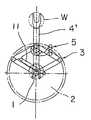
도1은 본 발명에 따른 1번째 구성예의 반송장치를 나타낸 것으로, 제1, 제2구동축(도시되지 않음)이 동축구조로 된 구동축(1; 이하, 편의상 단지 "구동축"이라 함)과, 이 구동축(1)을 축심위치(軸芯位置)에서 지지함과 더불어 구동축(1)의 구동원(驅動源)을 내장한 지지체(2), 이 지지체(2)의 구동축(1)에 기단부(基端部)쪽에서 연결된 개구리다리식 아암(3), 이 개구리다리식 아암(3)의 선단부쪽에 연결 된 웨이퍼지지체(4) 및, 이 웨이퍼지지체(4)의 회전을 규제하여 이 웨이퍼지지체(4)를 항상 일정한 자세로 유지되도록 하는 자세유지링크(5)를 갖춘 구조로 되어 있다. 상기 구동축(1)을 구성하는 제1구동축은 중공축(中空軸)으로 형성되고 제2구동축은 중공축(1)의 축심을 관통시키는 축으로 형성되고서, 이들 제1 및 제2구동축이 모두 구동원에 연결되어 각각 정역회전할 수 있도록 되어 있어서, 제1, 제2구동축을 반대방향으로 서로 동일한 각도만큼씩 회전시켜 개구리다리식 아암(3)을 신축시킬 수가 있고, 또 제1, 제2구동축을 같은 방향으로 동일한 각도만큼씩 회전시켜 개구리다리식 아암(3)에 의한 반송방향을 바뀌게 할 수가 있다. 따라서, 이렇게 구성된 반송장치를 예컨대 복수체임버처리장치에다 적용하면 복수의 처리실에 대해 쉽게 웨이퍼를 출입시킬 수가 있게 된다.Fig. 1 shows a conveying apparatus of a first configuration example according to the present invention, wherein a drive shaft 1 (hereinafter referred to simply as a “drive shaft”) having a first and a second drive shaft (not shown) having a coaxial structure, The
상기 개구리다리식 아암(3)은, 제1구동축에 기단부가 축지지되어 정역회전할 수 있도록 된 제1구동아암(6A)과, 제2구동축에 기단부가 축지지되어 정역회전할 수 있도록 된 제2구동아암(6B), 상기 제1구동아암(6A)의 선단부에 기단부가 제1관절(7)을 매개로 축지지되어 정역회전할 수 있도록 된 제1앞쪽아암(8A) 및, 상기 제2구동아암(6A)의 선단부에 기단부가 제2관절(9)을 매개로 축지지되어 정역회전할 수 있도록 된 제2앞쪽아암(8A)을 갖추고 있다. 상기 제1 및 제2앞쪽아암(8A, 8B)은 각각의 선단부가 동축구조를 한 제3 및 제4관절(10; 이하 편의상 단지 "관절"이라 함)을 매개로 웨이퍼지지체(4) 기단부의 폭방향 중앙에 축지지되어, 웨이퍼지지체(4)의 기단부에서 각각 정역회전할 수 있도록 구성되어 있다. 또, 상기 제1, 제2앞쪽아암(8A, 8B)은 제1, 제2구동아암(6A, 6B) 보다 조금 길게 형성되어 있다. 그리고, 상기 웨이퍼지지체(4)와 상기 1쌍의 제1, 제2앞쪽아암(8A, 8B)은 상호 자세유지링크(5)를 매개로 연결되어 있다.The frog-
또, 상기 자세유지링크(5)는 도1에 도시된 것과 같이, 제1앞쪽아암(8A)의 길이방향 중간부에 축(5A)을 매개로 한쪽 단부(端部)가 연결된 제1링크(5B)와, 이 제1링크(5B)의 다른쪽 단부에 축(5C)을 매개로 한쪽 단부가 연결되고서 웨이퍼지지체(4)의 기단부에 축(5D; 관절(10) 보다 선단부쪽으로 폭방향 중앙에 위치해 있음)을 매개로 다른쪽 단부가 연결된 제2링크(5E) 및, 이 제2링크(5E)의 축(5D) 근방에 축(5F)을 매개로 한쪽 단부가 연결됨과 더불어 제2앞쪽아암(8A)의 선단부 근방에 축(5G)을 매개로 다른쪽 단부가 연결된 제3링크(5H)로 구성되어 있다. 또, 도2에 파선으로 도시된 것과 같이 웨이퍼지지체(4)의 관절(10)과 축(5D) 사이에서 자세유지링크(5)의 제4링크(5I)가 만들어지도록 되어 있다.In addition, as shown in FIG. 1, the
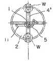
도2는 도1에 도시된 개구리다리식 아암(3) 및 자세유지링크(5)의 링크기구를 설명하기 위한 도면으로서, 이 도면을 참조하면서 자세유지링크(5)에 대해 설명한다.Fig. 2 is a view for explaining the link mechanism of the
자세유지링크(5) 중 제1링크(5B)의 길이와 제4링크(5I)의 길이가 같도록 설정되고, 제2링크(5E)의 길이와 관절(10)과 축(5A) 사이의 길이도 같도록 설정되어, 축(5A)과 축(5C), 축(5D) 및 관절(10)로 제1역평행링크기구가 구성되도록 되어 있다. 또, 제3링크(5H)의 길이와 제4링크(5I)의 길이가 같게 설정되고, 축(5D)과 축(5F) 사이의 길이와 축(5G)과 관절(10) 사이의 길이가 같아지도록 설정되어, 축(5D)과 축(5F), 축(5G) 및 관절(10)로 제2역평행링크기구가 구성되도록 되어 있다. 또한, 제1링크(5B)의 길이에 대한 제2링크(5E)의 비(比)와, 축(5D)과 축(5F) 사이의 길이에 대한 제3링크(5H)의 길이의 비가 같도록 설정되어 있다. 역평행링크기구(逆平行 Link 機構)라 함은 평행링크기구를 대각선으로 절곡해서 만들어지는 링크기구이다.The length of the
따라서 제1역평행기구에서는, 축(5A)을 사이에 둔 각도와 축(5D)을 사이에 둔 각도가 같고, 축(5C)을 사이에 둔 각도와 관절(10)을 사이에 둔 각도가 같아지게 된다. 또 제2역평행링크기구에서는, 축(5D)을 사이에 둔 각도와 축(5G)을 사이에 둔 각도가 같고, 축(5F)을 사이에 둔 각도와 관절(10)을 사이에 둔 각도가 같아지게 된다. 더구나, 상기 제1 및 제2역평행링크기구는 축(5D)을 사이에 둔 각도를 공유하기 때문에, 대응하는 각도가 모두 같아지게 되어 양자가 상사형을 이루게 되는 바, 이러한 관계는 개구리다리식 아암(3)이 어떤 자세를 하고 있더라도 성립되게 된다. 이상으로부터 제1역평행링크기구의 관절(10)을 사이에 둔 각도와 제2역평행링크기구의 관절(10)을 사이에 둔 각도가 항상 같아지게 되어, 웨이퍼지지체(4)로 구성되는 제4링크(5I)의 아암쪽으로 뻗은 연장선이 개구리다리식 아암(3)이 어떤 자세를 하고 있더라도 제1, 제2앞쪽아암(8A, 8B) 사이에 이루어지는 각을 2등분하게 된다. 따라서, 자세유지링크(5)는 웨이퍼지지체(4)를 항상 개구리다리식 아암(3)의 선단부에서 좌우대칭자세를 유지하게 됨으로써 개구리다리식 아암(3)의 신축에 따라 좌우로 흔들리지 않고 직진하게 되어, 웨이퍼를 목적하는 위치로 정확히 반송할 수가 있게 된다.Therefore, in the first antiparallel mechanism, the angle between the
도3은 본 발명에 따른 반송장치의 2번째 구성예를 나타낸 도면으로서, 이 2 번째 구성예에서는 개구리다리식 아암(3)의 신축거리가 길어지도록 하기 위해, 제1, 제2구동아암(6A, 6B) 및 제1, 제2앞쪽아암(8A, 8B)의 길이를 모두 같아지도록 하였다. 또, 1번째 구성예의 반송장치에서는 개구리다리식 아암(3)이 줄여져, 제1, 제2구동아암(6A, 6B)이 지지체(2)상에서 일직선으로 되어 구동축(1)과 제1, 제2앞쪽아암(8A, 8B)의 관절(10)이 겹쳐지는 위치가 사안점으로 된다. 이 위치에서는 관절(10)이 전후 어떤 방향으로도 이동할 수 있어서 구속을 받지 않기 때문에 개구리다리식 아암(3)이 기능하지 않게 된다.FIG. 3 is a view showing a second configuration example of the conveying apparatus according to the present invention. In this second configuration example, the first and second driving
여기서, 2번째 구성예에 대해 도3을 참조하면서 1번째 구성예와 동일부분 또는 그에 상당하는 부분에는 동일한 부호를 붙여 설명한다. 본 2번째 구성예의 반송장치는, 제1, 제2구동아암(6A, 6B) 및 제1, 제2앞쪽아암(8A, 8B)의 길이가 모두 같아지도록 설정되고, 사안점회피링크(11)를 설치하는 이외는 1번째 구성예에 준해서 구성되도록 되어 있다. 본 구성예에서의 사안점회피링크(11)는 예컨대 도3에 도시된 것과 같이, 제1구동아암(6A)과, 이 제1구동아암(6A)과 평행하게 마주보는 링크(11A), 이 링크(11A)의 한쪽 단부가 축(11B)을 매개로 연결되어 제1앞쪽아암(8A)에서 옆쪽으로 돌출하여 제1관절(7)과 축(11B)을 연결하는 돌출링크(11C) 및, 상기 링크(11A)의 다른쪽 단부가 축(11D)을 매개로 연결되어 제2구동아암(6B)에서 옆쪽으로 돌출하여 구동축(1)과 축(11D)을 연결하는 돌출링크(11E)로 이루어져 평행링크를 구성하도록 되어 있다. 즉, 링크(11A)의 길이와 제1구동아암(6A)의 길이가 같고, 돌출링크(11C)의 길이[제1관절(7)과 축(11B)의 거리]와 돌출링크(11E)의 길이[구동축(1)과 축(11D)의 거리]가 같아지도록 되어 있 다.Here, referring to Fig. 3 for the second configuration example, the same parts as or equivalent to the first configuration example will be described with the same reference numerals. The conveying apparatus of this 2nd structural example is set so that the length of the 1st,
따라서, 구동축(1)과 관절(10)이 상하로 겹쳐져 제1, 제2구동아암(6A, 6B)과 동일직선상에 위치하게 되고 그 위에 제1, 제2앞쪽아암(8A, 8B)이 겹쳐지더라도, 사안점회피링크(11)가 설치되어 있기 때문에 제1, 제2앞쪽아암(8A, 8B)은 구속을 받지 않고 제1, 제2구동아암(6A, 6B)의 이동방향에 대응해서 전후 어느 방향으로도 원활히 신장되어, 웨이퍼지지체(4)를 확실하게 전후 어느 방향으로도 이동시킬 수가 있고, 개구리다리식 아암(3)의 신축거리도 길어지게 할 수가 있게 된다.Therefore, the
또, 도3에 실선으로 도시된 웨이퍼지지체(4)는 1장의 웨이퍼를 반송하도록 된 것이나, 도3에 도시된 반송장치와 같이 제1, 제2앞쪽아암(8A, 8B)의 사안점을 회피하도록 된 형태의 반송장치인 경우에는, 지지체(2)를 기준으로 해서 반대방향으로도 마찬가지로 진출하도록 할 수가 있다. 그 때문에, 도3의 실선으로 나타내어진 부분인 웨이퍼지지체(4)의 기단부쪽에다 마찬가지의 웨이퍼지지체를 파선으로 도시된 것과 같이 연장해서 설치해서 2장의 웨이퍼를 지지하는 웨이퍼지지체(4')를 사용할 수가 있게 된다.In addition, the
다음에는 2장의 웨이퍼를 반송하는 형태로 된 반송장치의 동작에 대해 설명한다.Next, the operation of the conveying apparatus in the form of conveying two wafers will be described.
도4a에 도시된 것과 같이 자세유지링크(5)의 작용으로 개구리다리식 아암(3)이 똑바로 뻗은 상태에서 반도체웨이퍼(W)를 웨이퍼지지체(4')의 한쪽 지지부에서 넘겨받으면, 도4b에 도시된 것과 같이 구동축(1)의 제1, 제2구동축이 구동하여 개구리다리식 아암(3)이 오므라들게 되지만, 이 때 웨이퍼지지체(4')는 자세유지링크(5)의 작용으로 웨이퍼(W)를 넘겨받는 위치에서 곧바로 후퇴하게 된다.As shown in FIG. 4A, if the semiconductor wafer W is turned over from one support of the wafer support 4 'with the
계속해서 구동축(1)이 구동하면, 도4c에 도시된 것과 같이 지지체(2)상에서 개구리다리식 아암(3)의 제1, 제2구동아암이 웨이퍼지지체(4)와 직교하는 상태로 되어, 제1, 제2앞쪽아암이 제1, 제2구동아암과 겹쳐지게 된다. 이렇게 제1, 제2앞쪽아암이 제1, 제2구동아암과 겹쳐지게 되더라도, 사안점회피링크(11)가 사안점에 있지 않기 때문에, 계속 제1, 제2구동아암(6A, 6B)이 구동하면 사안점회피링크(11)가 작동하게 되고, 그에 수반해서 개구리다리식 아암(3)이 도4d에 도시된 것과 같이 반대쪽으로 신장되어 웨이퍼지지체(4')가 자세유지링크(5)와의 상호작용으로 도4a에 도시된 방향과 180°반대쪽으로 직진하게 된다. 그리고, 마지막으로는 도4e에 도시된 것과 같이 개구리다리식 아암(3)이 소정의 위치까지 신장되어 반도체웨이퍼(W)를 넘겨받게 된다.Subsequently, when the
도5는 본 발명에 따른 반송장치의 3번째 구성예를 나타낸 것으로, 상기 2번째 구성예와 동일한 부분 또는 그에 상당하는 부분에 대해서는 동일한 부호를 붙이기로 한다. 본 2번째 구성예의 반송장치에서는, 도5에 도시된 것과 같이 제2앞쪽아암 대신 링크(8C)가 설치되어, 이 링크(8C)를 매개로 제1앞쪽아암(8A; 이하 "앞쪽아암"이라 함)의 중간과 제2구동아암(6B)의 중간이 연결되도록 되어 있다. 또, 본 구성예에서는 제2앞쪽아암을 없앴기 때문에 자세유지링크(5)의 축(5A)이 제2앞쪽아암 대신 제2구동아암(6B)의 선단부(6C)에 연결되도록 되어 있다. 따라서, 본 구성예에서의 개구리다리식 아암(3)은 제1, 제2구동아암(6A, 6B)과 앞쪽아암(8A) 및 링크(8C)로 이루어진 제1평행링크기구를 구성하게 된다. 그리고, 상기 제1, 제2구동아암(6A, 6B) 및 앞쪽아암(8A)이 마름모꼴의 3변을 이루도록 되어 있기 때문에 제2구동아암(6B)의 선단부(6C)와 관절(10)의 거리가 항상 일정해지게 되어, 제1, 제2구동아암(6A, 6B)을 구동함으로써 개구리다리식 아암(3)을 신축시킬 수가 있게 된다.Fig. 5 shows a third configuration example of the conveying apparatus according to the present invention, in which the same parts as those in the second configuration example or corresponding parts will be denoted by the same reference numerals. In the conveying apparatus of the second configuration example, as shown in Fig. 5, a
또, 링크(8C)에 의한 평행링크기구가 사안점으로 된다 하더라도 사안점회피링크(11)가 작용하기 때문에, 앞쪽아암(8A)이 구속되지 않을 뿐만 아니라 제1, 제2구동아암(6A, 6B)의 구동방향에 대응해서 전후 어느 쪽으로도 원활히 신장되어 웨이퍼지지체(4')를 전후 어느 쪽으로도 이동시킬 수가 있어서, 개구리다리식 아암(3)의 신축거리를 길어지게 할 수가 있다. 또, 자세유지링크(5)의 축(5A)이 제2구동아암(6B)의 선단부(6C)에 연결되어 있기 때문에 축(5A)과 축(5C), 축(5D) 및 관절(10)로 제1역평행링크기구가 구성되게 된다. 따라서, 자세유지링크(5)가 웨이퍼지지체(4')를 항상 일정한 자세를 유지하도록 해서 개구리다리식 아암(3)의 신축에 수반하여 좌우로 흔들리지 않고 직진하여 도6a ~ 도6e에 도시된 것과 같이 웨이퍼지지체(4')를 확실하게 전후 어느 쪽으로도 이동시킬 수가 있어서, 웨이퍼를 목적하는 위치로 정확히 반송할 수가 있게 된다. 또, 제2앞쪽아암을 제거하였기 때문에 웨이퍼지지체(4')의 두께를 얇게 할 수가 있어서, 보다 좁은 개구에서도 웨이퍼지지체(4')를 통해 웨이퍼를 반송할 수가 있게 된다.In addition, even if the parallel link mechanism by the
이상 설명한 바와 같이 1번째 구성예에 의하면, 스틸벨트와 같은 벨트나 치차가 사용되지 않고 자세유지링크(5)가 설치되도록 되어 있기 때문에, 고온으로 부 식되기 쉬운 환경 하에서도 개구리다리식 아암(3)의 동작이 안정되고 일정한 자세를 유지하게 되어, 목적하는 위치까지 반도체웨이퍼(W)를 정확하고 확실하게 반송할 수가 있게 된다.As described above, according to the first configuration example, since the
또, 도3에 도시된 2번째 구성예에 의하면, 제1, 제2구동아암(6A, 6B) 및 제1, 제2앞쪽아암(8A, 8B)이 모두 같은 길이가 되도록 설정되고, 사안점회피링크(11)가 설치되어 개구리다리식 아암(3)의 사안점이 회피되도록 되어 있기 때문에, 개구리다리식 아암(3)이 지지체(2)를 기준으로 해서 전후 어느 쪽으로도 연속적으로 자유로이 신축할 수가 있게 되고, 그 때문에 도3에 도시된 것과 같이 2장의 반도체웨이퍼(W)를 동시에 반송할 수 있는 웨이퍼지지체(4')를 사용할 수가 있어서 반도체웨이퍼(W)의 반송효율을 높일 수가 있게 된다. 따라서, 본 구성예에서도 1번째 구성예에서와 같은 작용효과를 나타낼 수가 있게 된다.In addition, according to the second configuration example shown in Fig. 3, the first and second driving
또, 도5에 도시된 3번째 구성예에 의하면, 제2앞쪽아암이 생략되고 웨이퍼지지체(4')의 관절(10)의 두께가 얇게 되어 있어서, 보다 좁은 개구를 통해서도 웨이퍼를 반송할 수가 있게 된다. 그 외에, 본 구성예에 의해서도 2번째 구성예와 마찬가지 작용효과를 나타낼 수 있게 된다.In addition, according to the third configuration example shown in Fig. 5, the second front arm is omitted and the thickness of the joint 10 of the wafer support 4 'is thin, so that the wafer can be transported through a narrower opening. do. In addition, according to this structural example, the effect similar to the 2nd structural example can be exhibited.
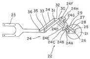
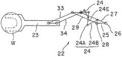
또한, 본 발명에 따른 반송장치의 4번째 구성예에 의하면, 예컨대 도7 ~ 도9에 도시된 것과 같이, 제1, 제2구동축(도시되지 않음)이 동축구조로 된 구동축(26; 이하 편의상 "구동축"이라 함)과, 이 구동축(26)을 축심위치에서 지지함과 더불어 구동축(26)의 구동원을 내장한 지지체(21), 이 지지체(21)의 구동축(26)에 기단부가 지지된 평행링크식 아암(22), 이 평행링크식 아암(22)의 선단부에 연결되어 반도체웨이퍼(W)를 보유지지하는 웨이퍼지지체(23) 및, 상기 평행링크식 아암(22)의 자세를 규제하여 항상 웨이퍼지지체를 일정한 자세로 지지하게 되는 자세유지링크(24)를 갖춘 구조로 되어 있다. 상기 구동축(26)을 구성하는 제1구동축은 중공축(中空軸)으로 이루어지고, 제2구동축은 중공축의 축심을 관통하는 축으로 되어 있다. 여기서, 이들 제1, 제2구동축은 모두 구동원으로 연결되어 각각 정역회전할 수 있도록 구성되어 있다. 즉, 제2구동축이 정역회전하게 되면 평행링크식 아암(22)이 신축될 수 있도록 되어 있다. 또, 제1, 제2구동축이 같은 방향으로 같은 각도씩 회전하게 되면 평행링크식 아암(22)에 의한 반송방향이 바꿔지도록 되어 있다. 따라서, 본 구성예의 반송장치를 예컨대 복수체임버식 처리장치에다 적용하는 경우에는, 복수의 처리실에 대해 자유로이 웨이퍼를 반입, 반출할 수가 있게 된다.Further, according to the fourth configuration example of the conveying apparatus according to the present invention, as shown in Figs. 7 to 9, for example, the first and second driving shafts (not shown) have a
상기 평행링크식 아암(22)은 도7 ~ 도9에 도시되 것과 같이 제1구동축에 기단부가 축지지된 어깨위치링크(25)와, 제2구동축에 기단부가 축지지되어 정역회전할 수 있도록 된 구동아암(27), 상기 어깨위치링크(25)의 다른쪽 단부에 기단부가 제1관절(28)을 매개로 축지지되어 정역회전할 수 있도록 된 종동아암(29), 상기 구동아암(27)과 종동아암(29) 각각의 선단부에 제2, 제3관절(30, 31)을 매개로 각각 축지지되어 정역회전할 수 있도록 된 팔꿈치위치링크(32), 이 팔꿈치위치링크(32)에 기단부가 제2관절(30)을 매개로 축지지되어 정역회전할 수 있도록 된 제1앞쪽아암(33) 및, 상기 팔꿈치위치링크(32)에 기단부가 제3관절(31)을 매개로 축지지되어 정역회전할 수 있도록 된 제2앞쪽아암(34)을 갖춘 구조로 되어 있다.The
그리고, 상기 웨이퍼지지체(23)는 제1, 제2앞쪽아암(33, 34) 각각의 선단부에 제4, 제5관절을 매개로 축지지되어, 평행링크식 아암(22)의 선단부에서 수평으로 지지되어 있다. 본 구성예에서는 구동아암(27)과 종동아암(29), 제1앞쪽아암(33) 및 제2앞쪽아암(34)이 모두 같은 길이가 되도록 설정되어 있다. 팔꿈치위치링크(32)와 구동아암(27), 제1앞쪽아암(33)은 서로 자세유지링크(24)를 매개로 연결되도록 되어 있다.The
그리고, 본 구성예의 자세유지링크(24)는 도7 ~ 도9에 도시된 것과 같이, 구동아암(27)의 길이방향 대략 중간부에 축(24A)을 매개로 한쪽 단부가 연결된 제1링크(24B)와, 이 제1링크(24B)의 다른쪽 단부에 축(24C)을 매개로 한쪽 단부가 연결됨과 더불어 팔꿈치위치링크(32)의 축(30)쪽으로부터 연장된 단부에 축(24D)을 매개로 다른쪽 단부가 연결된 제2링크(24E) 및, 제1앞쪽아암(33)의 제2관절(30)로부터 연장된 단부에 축(24F)을 매개로 한쪽 단부가 연결됨과 더불어 제2링크(24E)의 일부에 축(24G)을 매개로 다른쪽 단부가 연결된 제3링크(24H)로 구성되어 있다.And, as shown in Figs. 7 to 9, the
도10은 도9에 도시된 평행링크식 아암(22) 및 자세유지링크(24)의 링크기구를 설명하기 위한 설명도로서, 이 설명도를 참조하면서 자세유지링크(24)에 대해 설명한다.Fig. 10 is an explanatory diagram for explaining the link mechanism of the
평행링크식 아암(22)은, 고정된 어깨위치링크(25)와, 구동아암(27), 종동아암(29) 및 팔꿈치위치링크(32)로 구성된 제1평행링크기구, 팔꿈치위치링크(32) 및, 제1, 제2앞쪽아암(33, 34) 및 웨이퍼지지체(23)의 관절(35, 36) 사이에 이루어진 제2평행링크기구로 구성되어 있다.The
상기 자세유지링크(24) 중 제1링크(24B)의 길이와 제2관절(30)과 축(27) 사이의 길이가 같아지도록 설정되고, 제2링크(24E)의 길이와 구동아암(27)의 제2관절(30)과 축(27) 사이의 길이도 같아지도록 설정되어, 축(24A)과 축(24C), 축(24D) 및 관절(30)로 본 구성예에서의 제1역평행링크기구가 구성되도록 되어 있다. 또, 구동아암(27)의 제2관절(30)과 축(24F) 사이의 거리와 제2링크(24E)의 축(24D)과 축(24G) 사이의 거리가 같아지도록 설정되고, 제3링크(24H)의 길이와 팔꿈치위치링크(32)의 제2관절(30)과 축(24D) 사이의 거리도 같아지도록 설정되어, 축(24D)과 축(24G), 축(24F) 및 관절(30)로 본 구성예에서의 제2역평행링크기구가 구성되도록 되어 있다. 그리고, 제1링크(24B)의 길이에 대한 축(24A)과 제2관절(30) 사이의 길이의 비와, 제2관절(30)과 축(24F) 사이의 길이에 대한 제3링크(24H)의 길이의 비가 같아지지 않도록 설정되어 있다.The length of the
따라서 제1역평행링크기구에서는, 축(24A)을 사이에 둔 각도와 축(24D)을 사이에 둔 각도가 같고, 축(24C)을 사이에 둔 각도와 관절(30)을 사이에 둔 각도가 같아지게 된다. 또, 제2역평행기구에서는, 축(24d)을 사이에 둔 각도와 축(24f)을 사이에 둔 각도가 같고, 축(24g)을 사이에 둔 각도와 관절(30)을 사이에 둔 각도가 같아지게 된다. 그리고, 상기 제1, 제2역평행링크기구는 축(24d)을 사이에 두고 있기 때문에, 대응하는 각도가 모두 같아져 양자가 상사형을 이루도록 되어 있다. 이들의 관계는 평행링크식 아암(22)이 어떤 자세를 하게 되더라도 성립되게 된다. 이상으로부터 제1역평행링크기구의 관절(30)을 사이에 둔 각도와 제2역평행링크기구의 관절(30)을 사이에 둔 각도가 항상 같아져, 팔꿈치위치링크(32)는 평행링크식 아암(22)이 어떤 자세를 하고 있더라도 구동아암(27)과 제1앞쪽아암(33) 사이의 각을 2등분하게 된다.Therefore, in the first antiparallel link mechanism, the angle between the
따라서, 구동아암(27)이 구동축(26)의 제2구동축을 매개로 반시계방향으로 선회하면, 팔꿈치위치링크(32)는 제1평행링크기구의 작용에 따라 선회하지 않기 때문에, 제1앞쪽아암이 자세유지링크(24)의 작용에 따라 시계방향으로 같은 각도만큼 선회하게 된다. 그 결과, 웨이퍼지지체(23)가 어깨위치링크(25)상을 직진해서 그 연장선상에 배치된 목적하는 위치로 반도체웨이퍼(W)를 정확하게 반송할 수 있게 된다.Therefore, when the
다음에는 도11을 참조하면서 동작에 대해 설명한다. 도11a에 도시된 것과 같이 자세유지링크(24)의 작용으로 평행링크식 아암(22)이 지지체(도11에서는 생략되어 있음)의 오른쪽 끝까지 이동한 상태로부터 구동축(26)의 제2구동축이 구동해서 평행링크식 아암(22)의 구동아암(27) 및 종동아암(29)이 반시계방향으로 선회하게 되면, 자세유지링크(24)의 작용으로 제1, 제2앞쪽아암(33, 34)이 팔꿈치위치링크(32)를 기준으로 해서 시계방향으로 선회하게 되고, 그 결과 도11a의 위치에서 왼쪽으로 직진하여 도11b에 도시된 것과 같이 제1, 제2앞쪽아암(33, 34)이 구동아암(27) 및 종동아암(29)상에서 겹쳐짐과 더불어 웨이퍼지지체(23)의 관절(35, 36)이 구동축(26)과 관절(28)상에 겹쳐지게 된다.Next, the operation will be described with reference to FIG. As shown in Fig. 11A, the second drive shaft of the
계속해서 구동축(1)이 구동하게 되면, 구동아암(27)과 종동아암(29)이 반시계방향으로 선회하고, 웨이퍼지지체(23)는 그대로 직진해서 통과하게 되어, 최종적으로는 도11d에 도시된 반도체웨이퍼(W)를 넘겨받는 위치까지 직진하여 반도체웨이 퍼의 수도동작(受渡動作)이 이루어지게 된다.Subsequently, when the
이상 설명한 바와 같이 4번째 구성예에 의하면, 평행식링크(22)의 구동아암(27)과 팔꿈치위치링크(32)의 제1앞쪽아암(33)을 상호 자세유지링크(24)로 연결시켜 놓았기 때문에, 고온으로 부식되기 쉬운 환경에 있게 되더라도 웨이퍼지지체(23)의 동작이 안정되게 되고, 또 웨이퍼지지체(23)가 항상 어깨위치링크(25)상을 직진하게 되어 항상 일정한 자세를 유지함으로써, 목적하는 위치까지 반도체웨이퍼(W)를 정확하고 확실하게 반송할 수가 있게 된다.As described above, according to the fourth configuration example, the
또, 본 발명의 개구리다리식 아암을 가진 반송장치는 도12 ~ 도15에 도시된 것과 같이 구성할 수도 있는 바, 이러한 반송장치에 의해서도 1번째, 2번째 구성예와 마찬가지 작용효과를 기할 수가 있게 된다.In addition, the conveying apparatus having the frog leg type arm of the present invention can also be configured as shown in Figs. 12 to 15, so that the conveying apparatus can achieve the same effects as the first and second structural examples. do.
도12에 도시된 반송장치는, 동축구조의 구동축(31)과, 개구리다리식 아암(32), 웨이퍼지지체(33) 및, 이 웨이퍼지지체(33)와 상기 개구리다리식 아암(32)을 연결하는 자세유지링크(34)를 구비하고 있다. 개구리다리식 아암(32)은 제1, 제2구동아암(32A, 32B) 및 제1, 제2앞쪽아암(32C, 32D)을 갖고서 관절(35)을 매개로 웨이퍼지지체(33)와 연결되어 있다.The conveying apparatus shown in FIG. 12 connects the
상기 자세유지링크(34)는 도12에 도시된 것과 같이, 한쪽 단부가 제1앞쪽아암(34A)에 축(34A)을 매개로 연결된 제1링크(34B)와, 이 제1링크(34B)의 다른쪽 단부에 축(34C)을 매개로 한쪽 단부가 연결됨과 더불어 웨이퍼지지체(33)의 관절(35)의 길이방향 연장선상에 다른쪽 단부가 축(34D)을 매개로 연결된 제2링크(34E), 이 제2링크(34E)의 도중에 배치된 축(34F)에 한쪽 단부가 연결된 제3링크(34G), 제3링 크(34G)의 다른쪽 단부에 축(34H)을 매개로 한쪽 단부가 연결된 제2링크(34E)와 평행한 제4링크(34I) 및, 이 제4링크(34I)의 다른쪽 단부에 축(34J)을 매개로 한쪽 단부가 연결됨과 더불어 웨이퍼지지체(33)에 축(34D)을 매개로 다른쪽 단부가 연결된 제3링크(34G)와 평행한 제5링크(34K)를 갖도록 되어 있다. 또, 상기 제4링크(34I)는 제2앞쪽아암(32D)과 축(34L)을 매개로 연결되어 있다. 그리고, 상기 각 링크는 모두 각 축에서 회전할 수 있도록 되어 있다.As shown in Fig. 12, the
제1링크(34B)의 길이와 축(34D)과 관절(35) 사이의 길이가 같아지도록 설정되고, 제2링크(34E)의 길이와 축(34A)과 축(35) 사이의 거리도 같아지도록 설정되어, 축(34A)과 축(34C), 축(34D) 및 관절(35)로 제1역평행링크기구가 구성되도록 되어 있다. 또, 축(34D)과 관절(35) 사이의 길이와 축(34L)과 제2링크(34E)의 가상점(36) 사이의 길이(이들 양자를 잇는 파선은 제5링크(34K)와 평행하도록 되어 있다)가 같아지도록 설정되고, 축(34D)과 가상점(36) 사이의 길이와 축(34L)과 관절(35) 사이의 길이도 같아지도록 설정되어, 축(34D)과 가상점(36), 축(34L) 및 관절(35)로 제2역평행링크기구가 구성되도록 되어 있다. 그리고, 제1링크(34B)의 길이에 대한 제2링크(34E)의 길이의 비와, 축(34D)와 가상점(36) 사이의 길이에 대한 축(34D)과 관절(35) 사이의 거리의 비가 같아지도록 설정되어 있다. 또한, 제2링크(34E)와 축(34D)과 관절(35)의 연결성으로 이루어지는 각은 제1, 제2역평행링크기구로 공유하게 되어, 개구리다리식 아암(32)이 어떤 신축상태로 되어 있더라도 제1, 제2역평행링크기구가 상호 상관관계를 갖게 됨으로써, 제1역평행링크기구의 관절(35)에서의 꼭지각이 항상 같아지게 된다. 따라서, 웨이퍼지지체(33)의 축(34D)과 관절(35)을 있는 선이 항상 제1, 제2앞쪽아암(32C, 32D) 사이에 이루어지는 각을 2등분해서 웨이퍼지지체(33)가 항상 좌우로 흔들리지 않고 일정한 자세를 유지할 수 있게 된다.The length of the
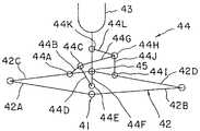
도13에 도시된 반송장치는, 동축구조의 구동축(41)과, 개구리다리식 아암(42), 웨이퍼지지체(43) 및, 이 웨이퍼지지체(43)와 상기 개구리다리식 아암(42)을 연결하는 자세유지링크(44)를 구비하고 있다. 개구리다리식 아암(42)은 제1, 제2구동아암(42A, 42B) 및 제1, 제2앞쪽아암(42C, 42D)을 갖고서 관절(45)을 매개로 웨이퍼지지체(43)와 연결되어 있다.The conveying apparatus shown in Fig. 13 connects the
상기 자세유지링크(44)는 도13에 도시된 것과 같이, 한쪽 단부가 제1앞쪽아암(42C)에 축(44A)을 매개로 연결된 제1링크(44B)와, 이 제1링크(34B)의 다른쪽 단부에 축(44C)을 매개로 한쪽 단부가 연결된 제2링크(44D), 이 제2링크(44D)의 다른쪽 단부에 축(44E)을 매개로 한쪽 단부가 연결됨과 더불어 다른쪽 단부가 관절(45)에 연결된 제3링크[44F; 웨이퍼지지체의 기단부의 축심상에서 관절(45)에 의해 기단부에 기단부의 일부로 또는 그 연장부에 일체화되어 있음], 제1링크(44B)의 다른쪽 단부에 축(44C)을 매개로 한쪽 단부가 연결된 제4링크(44G), 이 제4링크(44G)의 다른쪽 단부에 축(44H)을 매개로 한쪽 단부가 연결됨과 더불어 제2앞쪽아암(42D)에 배치된 축(44I)에 다른쪽 단부가 연결된 제5링크(44J), 이들 제4, 제5링크(44G, 44J)의 축(44H)에 한쪽 단부가 연결됨과 더불어 웨이퍼지지체(43)의 관절(45)의 길이방향 연장선상에 배치된 축(44K)에 다른쪽 단부가 연결된 제6링크(44L)를 갖도록 되어 있다. 그리고, 각 링크는 모두 각 축에서 회전할 수 있도록 되어 있다.As shown in Fig. 13, the
제1링크(44B)의 길이와 제3링크(44F)의 길이가 같아지도록 설정되고, 제2링크(44D)의 길이와 제1앞쪽아암(42C)의 축(44A)과 관절(45) 사이의 길이도 같아지도록 설정되어, 축(44A)과 축(44C), 축(44E) 및 관절(45)로 제1역평행링크기구가 구성되도록 되어 있다. 또, 제2링크(44D)의 길이와 제5링크(44L)의 길이가 같아지도록 설정되고, 제4링크(44G)의 길이와 웨이퍼지지체(43)의 기단부의 축(44E)과 축(44K) 사이의 길이도 같아지도록 설정되어, 축(44C)과 축(44E), 축(44K) 및 축(44H)으로 제2역평행링크기구가 구성되도록 되어 있다. 또한, 제1링크(44B)의 길이에 대한 제4링크(44G)의 길이에 대한 비와, 제2링크(44D)의 길이에 대한 제4링크(44G)의 길이의 비가 같도록 설정되어 있다. 그리고, 제2링크(44D)와, 축(44E)과 관절(45)을 잇는 선으로 만들어지는 각이 제1, 제2역평행링크기구에서 공유하도록 되어 있어서, 개구리다리식 아암(42)이 어떤 신축상태에 있더라도 상기 제1, 제2역평행링크기구가 상호 상사관계에 있게 된다. 또, 축(44I)과 축(44H), 축(44K) 및 관절(45)로 이루어지는 4각형이 평행4변형이 되도록 설정되어 있다. 이와 같이 됨으로써, 제1역평행링크기구의 관절(45)에서의 꼭지각과 제2역평행링크기구의 축(44K)에서의 꼭지각이 항상 같게 되고, 더구나 이 축(44K)에서의 꼭지각과 제2앞쪽아암(42D)과 축(44E)과 관절(45)을 잇는 선으로 만들어지는 각이 같아지게 되어, 제2앞쪽아암(42D)과 축(44E)과 관절(4)을 잇는 선으로 만들어지는 각과 제1역평행링크기구의 관절(45)에서의 꼭지각이 같아지게 된다. 따라서, 축(44E)과 축(44K)을 잇는 선이 제1앞쪽아암(42C)과 제2앞쪽아암(42D)이 이루는 각을 항상 2등분하여, 웨이퍼지지체(43)가 항상 좌우로 흔들리지 않고 일정한 자세를 유지하게 된다.The length of the
도14에 도시된 반송장치는, 동축구조로 된 구동축(51)과, 개구리다리식 아암(52), 웨이퍼지지체(53) 및, 이 웨이퍼지지체(53)와 상기 개구리다리식 아암(52)을 연결하는 자세유지링크(54)를 구비하고 있다. 상기 개구리다리식 아암(52)은, 제1, 제2구동아암(52A, 52B) 및 제1, 제2앞쪽아암(52C, 52D)을 갖고서, 웨이퍼지지체(53)의 기단부의 길이방향과 직교하는 방향으로 나란히 설치된 관절(55, 56)을 매개로 웨이퍼지지체(53)와 연결되도록 되어 있다.In the conveying apparatus shown in Fig. 14, a
상기 자세유지링크(54)는 도14에 도시된 것과 같이, 한쪽 단부가 제1앞쪽아암(52C)에 고정축(54A)을 매개로 연결된 제1고정링크(54B)와, 이 제1고정링크(54B)의 다른쪽 단부에 축(54C)을 매개로 한쪽 단부가 연결됨과 더불어 관절(55, 56)과 2등변3각형을 이루는 웨이퍼지지체(53)의 기단부에 배치된 축(54F)을 매개로 다른쪽 단부가 연결된 제2링크(54G), 이 제2링크(54G)에 배치된 고정축(54H)에 연결된 제2고정링크(54I), 이 제2고정링크(54I)의 다른쪽 단부에 축(54J)을 매개로 연결된 제3링크(54K) 및, 이 제3링크(54K)의 다른쪽 단부에 축(54L)을 매개로 한쪽 단부가 연결됨과 더불어 제2앞쪽아암(52D)의 고정축(54M)에 다른쪽 단부가 연결된 제3고정링크(54N)를 갖도록 되어 있다.As shown in Fig. 14, the
제1링크(54D)의 길이와 웨이퍼지지체(53)에서의 축(54F)과 관절(55) 사이의 길이가 같아지도록 설정되고, 제2링크(54G)의 길이와 축(54C)과 관절(55)을 잇는 파선으로 나타내어진 선의 길이도 같아지도록 설정되어, 축(54C)과 축(54E), 축(54F) 및 관절(55)로 제1역평행링크기구가 구성되도록 되어 있다. 또, 제3링크(54K)의 길이와 축(54F)과 관절(56) 사이를 잇는 파선으로 나타내어진 선의 길이가 같도록 설정되고, 축(54F)과 축(54J) 사이를 잇는 파선으로 나타내어진 선의 길이와 축(54L)과 관절(56) 사이를 잇는 파선으로 나타내어진 선의 길이도 같은 길이로 설정되어, 축(54F)과 축(54J), 축(54L) 및 관절(56)로 제2역평행링크기구가 구성되도록 되어 있다. 그리고, 제1링크(54D)의 길이에 대한 제2링크(54G)의 길이의 비와, 축(54F)과 축(54J) 사이의 길이에 대한 제3링크(54K)의 길이의 비가 같도록 설정되어 있다. 이 경우, 제1, 제2역평행링크기구에서 공유하는 각은 아니지만, 제1역평행링크기구의 축(54F)에서의 꼭지각과 제2역평행링크기구의 축(54F)에서의 꼭지각이 항상 같아지도록 제2고정링크(54I)의 길이와 관절(55, 56) 사이의 길이가 설정되어 있기 때문에, 개구리다리식 아암(52)이 어떤 신축위치에 있더라도 제1, 제2역평행링크기구가 서로 상사관계에 있게 된다. 이렇게 됨으로써, 제1역평행링크기구의 관절(55)에서의 꼭지각과 제2역평행링크기구의 관절(56)에서의 꼭지각이 항상 같아지게 된다. 따라서, 이 경우에도 개구리다리식 아암(52)이 동작할 때 웨이퍼지지체(53)가 항상 좌우로 흔들리지 않고 일정한 자세를 유지하게 된다.The length of the
도15에 도시된 반송장치는, 동축구조로 된 구동축(61)과, 개구리다리식 아암(62), 웨이퍼지지체(63) 및, 이 웨이퍼지지체(63)와 상기 개구리다리식 아암(62)을 연결하는 자세유지링크(64)를 구비하고 있다. 상기 개구리다리식 아암(62)은, 제1, 제2구동아암(62A, 62B) 및 제1, 제2앞쪽아암(62C, 62D)을 갖고서, 웨이퍼지지체(63)의 기단부의 길이방향과 직교하는 방향으로 나란히 설치된 관절(65, 66)을 매개로 웨이퍼지지체(63)와 연결되도록 되어 있다.The conveying apparatus shown in Fig. 15 has a
상기 자세유지링크(64)는 도15에 도시된 것과 같이, 한쪽 단부가 관절(65)에 연결된 제1링크[64A; 제1앞쪽아암(62C)의 연장부]와, 이 제1링크(64A)의 다른쪽 단부에 축(64B)을 매개로 한쪽 단부가 연결된 제2링크(64C), 이 제2링크(64C)의 다른쪽 단부에 축(64D)을 매개로 연결됨과 더불어 웨이퍼지지체(63)의 축(64E)에 한쪽 단부가 연결된 제3링크(64F), 이 제3링크(64F)의 다른쪽 단부에 축(64G)을 매개로 한쪽 단부가 연결됨과 더불어 다른쪽 단부가 축(64H)을 매개로 제2앞쪽아암(62D)에 연결된 제4링크(64I)를 갖도록 되어 있다. 축(64E)은 관절(65, 66)의 연장선상에 배치되도록 되어 있다. 그리고, 각 링크는 모두 각 축에서 회전할 수 있도록 되어 있다.As shown in Fig. 15, the
제1링크(64A)의 길이와 제3링크(64F)의 축(64D)과 축(64W) 사이의 길이가 같아지도록 설정되고, 제2링크(64C)의 길이와 관절(65)과 축(64E) 사이의 길이도 같아지도록 설정되어, 관절(65)과 축(64B), 축(64D) 및 축(64E)으로 제1역평행링크기구가 구성되도록 되어 있다. 또, 관절(66)과 축(64E) 사이의 길이와 제4링크(64I)의 길이가 같도록 설정되고, 제3링크(64F)의 길이와 제2앞쪽아암(62D)의 관절(66)과 축(64H) 사이의 길이도 같아지도록 설정되어, 관절(66)과 축(64E), 축(64G) 및 축(54H)으로 제2역평행링크기구가 구성되도록 되어 있다. 그리고, 제1링크(64A)의 길이에 대한 제2링크(64C)의 길이의 비와, 제4링크(64I)의 길이에 대한 제3링크(64F)의 길이의 비가 같도록 설정되어 있다. 그리고, 관절(66)과 축(64E)을 잇는 선과 제3링크(64F)로 만들어지는 각을 제1, 제2역평행링크기구에서 공유하도록 되어 있어서, 개구리다리식 아암(62)이 어떤 신축위치에 있더라도 제1, 제2역 평행링크기구가 서로 상사관계에 있게 된다. 이렇게 됨으로써, 제1역평행링크기구의 관절(65)에서의 꼭지각과 제2역평행링크기구의 관절(66)에서의 꼭지각이 항상 같아지게 된다. 따라서, 이 경우에도 개구리다리식 아암(62)이 동작할 때 웨이퍼지지체(63)가 항상 좌우로 흔들리지 않고 일정한 자세를 유지하게 된다.The length of the first link 64A and the length between the
또, 본 발명에서의 평행링크식 아암을 가진 반송장치는 도17 및 도18에 도시된 것과 같이 구성될 수도 있는 바, 이들 반송장치에 의해서도 앞에서 설명한 4번째 실시예와 마찬가지 작용효과를 기대할 수가 있게 된다.In addition, the conveying apparatus having the parallel link arm in the present invention may be configured as shown in Figs. 17 and 18, so that these conveying apparatuses can have the same operational effects as in the fourth embodiment described above. do.
도16에 도시된 반송장치는, 지지체(도시되지 않음)의 구동축(71)에 기단부가 지지된 평행링크식 아암(73)과, 이 평행링크식 아암(73)의 선단부에 연결되어 반도체웨이퍼(W)를 보유지지하는 웨이퍼지지체(74) 및, 평행링크식 아암(73)의 자세를 규제하여 항상 웨이퍼지지체(74)를 일정한 자세로 유지되도록 하는 자세유지링크(75)를 갖춘 구조로 되어 있다. 이 반송장치에서는 웨이퍼지지체(74)와 자세유지링크(75)가 부착되는 위치가 다르게 되어 있는 점 외에는 도5에 도시된 반송장치와 마찬가지로 구성되어 있다. 웨이퍼지지체(74)는 2장의 반도체웨이퍼를 보유지지하는 형식으로, 평행링크식 아암(73)에서 지지하는 형태는 도5에 도시된 것과 다르지 않다.The conveying apparatus shown in Fig. 16 includes a
상기 평행링크식 아암(73)은 도16에 도시된 것과 같이, 어깨위치링크(76)와 구동아암(78), 팔꿈치위치링크(80) 및 제2앞쪽아암(81)을 갖춘 구조로 되어 있다. 참조부호 82 ~ 85는 모두 관절이다.As shown in FIG. 16, the
도16에 도시된 자세유지링크(75)는, 구동아암(77)의 연장부 끝에 축(75A)을 매개로 한쪽 단부가 연결된 제1링크(75B)와, 이 제1링크(75B)의 다른쪽 단부에 축(75C)을 매개로 연결된 제2링크(75D) 및, 이 제2링크(75D)의 한쪽 단부에 축(75E)을 매개로 한쪽 단부가 연결됨과 더불어 다른쪽 단부가 축(75F)을 매개로 제1앞쪽아암(80)에 연결된 제3링크(75G)를 갖춘 구조로 되어 있다. 또, 상기 제2링크(75C)의 다른쪽 단부에는 팔꿈치위치링크(79)의 연장부 끝에 축(75H)을 매개로 연결되어 있다.The
상기 자세유지링크(75) 중 제1링크(75B)의 길이와 팔꿈치위치링크(79)의 관절(83)과 축(75H) 사이의 길이가 같아지도록 설정되고, 구동아암(77)의 관절(83)과 축(75A) 사이의 길이와 제2링크(75D)의 축(75C)과 축(75H) 사이의 길이도 같아지도록 설정되어, 축(75A)과 축(75C), 축(75H) 및 관절(83)로 제1역평행링크기구가 구성되도록 되어 있다. 또, 제3링크(75G)의 길이와 팔꿈치위치링크(79)의 관절(83)과 축(75H) 사이의 길이가 같아지도록 설정되고, 제2링크(75D)의 길이와 제1앞쪽아암(80)의 관절(83)과 축(75F) 사이의 길이도 같아지도록 설정되어, 축(75H)과 축(75E), 축(75F) 및 관절(83)로 제2역평행링크기구가 구성되도록 되어 있다. 또한, 제1링크(75B)의 길이에 대한 구동아암(77)의 관절(83)과 축(75A) 사이의 비와, 제2링크(75D)의 길이에 대한 제3링(75G)의 길이의 비가 같도록 설정되어 있다. 그리고, 제1, 제2역평행링크기구는 축(75H)을 사이에 둔 각도를 공유하고 있기 때문에, 대응하는 각도가 모두 같아지게 되어 양자가 상사형상을 이루게 된다.The length of the
따라서, 구동아암(77)이 구동축(71)의 제2구동축을 매개로 반시계방향으로 선회하게 되면, 웨이퍼지지체(74)가 자세유지링크(75)를 매개로 어깨위치링크(76) 상을 직진하여, 그 연장선상에 배치된 목적하는 위치로 반도체웨이퍼(W)를 정확하게 반송할 수가 있게 된다.Therefore, when the driving
또, 도17에 도시된 반송장치와 도16에 도시된 반송장치에서 동일한 부분 또는 그에 상당하는 부분에는 20만큼 큰 숫자를 붙이고서 그에 대한 설명은 생략하기로 하고, 주로 자세유지링크(95)에 대해서만 설명한다. 이 평행링크식 아암(93)의 경우에는 제1, 제2앞쪽아암(100, 101)이 구동아암(97) 및 종동아암(98)과는 직접 연결되지 않고, 팔꿈치위치링크(99)에서 오른쪽으로 치우친 위치에서 팔꿈치위치링크(99)에 대해 관절(106, 107)을 매개로 연결되도록 되어 있다.In addition, in the conveying apparatus shown in FIG. 17 and the conveying apparatus shown in FIG. 16, the same portion or a corresponding portion thereof is attached with a number as large as 20, and description thereof will be omitted, and the
도17에 도시된 자세유지링크(95)는, 구동아암(97)의 연장부 끝에 축(95A)을 매개로 한쪽 단부가 연결된 제1링크(95B)와, 이 제1링크(95B)의 다른쪽 단부에 축(95C)을 매개로 한쪽 단부가 제2링크(95D) 및, 상기 제1링크(95B)의 다른쪽 단부에 축(95C)을 매개로 한쪽 단부가 연결된 제3링크(95E)를 갖춘 구조로 되어 있다. 또, 제2링크(95D)의 다른쪽 단부는 제2앞쪽아암(101)에 축(95F)을 매개로 연결되고, 제3링크(95E)의 다른쪽 단부는 팔꿈치위치링크(99)에 관절(103)을 매개로 연결되어 있다.The
그리고, 제1링크(95B)의 길이와 팔꿈치위치링크(99)의 관절(102)과 관절(103) 사이의 길이가 같아지도록 설정되고, 제3링크(95E)의 길이와 구동아암(97)의 관절(103)과 축(95A) 사이의 길이도 같아지도록 설정되어, 축(95A)과 축(96C), 관절(102) 및 관절(103)로 제1역평행링크기구가 구성되도록 되어 있다.The length of the
또, 제2링크(95D)의 길이와 팔꿈치위치링크(99)의 관절(102)과 관절(106) 사이의 길이가 같아지도록 설정되고, 제3링크(95E)의 길이와 제2앞쪽아암(101)의 관절(106)과 축(95F) 사이의 길이도 같아지도록 설정되어, 축(95C)과 축(95F), 관절(106) 및 관절(102)로 제2역평행링크기구가 구성되도록 되어 있다. 또한, 제1링크(95B)의 길이에 대한 제3링크(95E)의 길이의 비와, 제3링크(95E)의 길이에 대한 제2링크(95D)의 길이의 비가 같도록 설정되어 있다. 그리고, 상기 제1, 제2역평행링크기구는 관절(102)을 사이에 둔 각도를 공유하고 있기 때문에, 대응하는 각도가 모두 같아져 양자가 상사형상을 하도록 되어 있다. 따라서, 구동아암(97)이 구동축(91)의 제2구동축을 매개로 반시계방향으로 선회하게 되면, 웨이퍼지지체(94)가 자세유지링크(95)를 매개로 어깨위치링크(96)상을 직진하여, 그 연장선상에 배치된 목적하는 위치로 반도체웨이퍼(w)를 정확히 반송할 수 있게 된다.Further, the length of the
한편, 본 발명에 따른 개구리다리식 아암 또는 평행링크식 아암을 가진 반송장치는 상기 각 구성예에 하등 제한을 받지 않고, 2개의 역평행링크기구를 자세유지링크로 갖춰져 있다면 모두 본 발명에 포함되게 된다. 또 2개의 역평행링크기구을 명확히 갖고 있지 않는다 하더라도, 도12나 도14에 도시된 반송장치와 같이 다른 평행링크기구나 굴곡시켜진 고정링크에 의해 2점 사이의 거리가 일정하게 유지되고, 거기에 가상선을 그으면 2개의 역평행링크기구가 나타나 그것이 자세유지링크로 작용한다면 모두 본 발명에 포함되게 된다.
On the other hand, the conveying device having a frog-legged arm or a parallel link arm according to the present invention is not limited to each of the above configuration, if both the anti-parallel link mechanism is provided as a posture maintaining link to be included in the present invention do. Even if the two anti-parallel link mechanisms are not clearly defined, the distance between the two points is kept constant by another parallel link mechanism or a bent fixed link, such as the conveying apparatus shown in Figs. When the imaginary line is drawn, two antiparallel link mechanisms appear and all of them are included in the present invention if they act as posture maintenance links.
이상 설명한 바와 같이, 본 발명의 1번째 또는 5번째와 같은 구성에 의하면, 벨트나 치차와 같은 전달기구를 사용하지 않고서 내열성과 내부식성이 뛰어나 항상 안정된 자세로 반도체웨이퍼와 같은 피반송체를 정확하고 확실하게 반송할 수 있는 개구리다리식 아암 또는 평행링크식 아암을 가진 반송장치를 제공할 수 있게 된다.As described above, according to the first or fifth configuration of the present invention, it is excellent in heat resistance and corrosion resistance without using a transmission mechanism such as a belt or a gear, and it is possible to accurately carry a carrier such as a semiconductor wafer in a stable posture at all times. It is possible to provide a conveying apparatus having a frog leg arm or a parallel link arm which can be reliably conveyed.
또, 상기 2번째 또는 4번째와 같은 구성에 의하면, 1번째 구성의 반송장치에서 지지체를 중심으로 해서 그 전후방향으로 자유로이 피반송체를 반송할 수 있는 개구리다리식 아암형태의 아암을 가진 반송장치를 제공할 수 있게 된다.Further, according to the second or fourth configuration, the conveying apparatus having an arm of a frog leg type arm capable of freely conveying the conveyed object in the front and rear direction with respect to the support in the conveying apparatus of the first configuration. Can be provided.
또한, 상기 3번째 구성에 의하면, 상기 1번째 구성의 반송체와 같은 작용효과를 갖게 됨과 더불어 좁은 개구부에 대해서도 피반송체를 반입, 반출할 수 있는 개구리다리식 아암형태의 아암을 가진 반송장치를 제공할 수 있게 된다.According to the third aspect of the present invention, there is provided a conveying apparatus having an arm of a frog-legged arm capable of bringing in and carrying out a conveyed object even in a narrow opening while having the same effect as that of the conveyed body of the first configuration. It can be provided.
Claims (6)
Translated fromKoreanApplications Claiming Priority (2)
| Application Number | Priority Date | Filing Date | Title |
|---|---|---|---|
| JP10343585AJP2000150617A (en) | 1998-11-17 | 1998-11-17 | Transporter |
| JP?10-343585 | 1998-11-17 |
Publications (2)
| Publication Number | Publication Date |
|---|---|
| KR20010089466A KR20010089466A (en) | 2001-10-06 |
| KR100617504B1true KR100617504B1 (en) | 2006-09-01 |
Family
ID=18362674
Family Applications (1)
| Application Number | Title | Priority Date | Filing Date |
|---|---|---|---|
| KR1020017006186AExpired - Fee RelatedKR100617504B1 (en) | 1998-11-17 | 1999-11-15 | Conveying device |
Country Status (7)
| Country | Link |
|---|---|
| US (2) | US6450757B1 (en) |
| EP (1) | EP1207025B1 (en) |
| JP (1) | JP2000150617A (en) |
| KR (1) | KR100617504B1 (en) |
| DE (1) | DE69940220D1 (en) |
| TW (1) | TW444243B (en) |
| WO (1) | WO2000029176A1 (en) |
Families Citing this family (420)
| Publication number | Priority date | Publication date | Assignee | Title |
|---|---|---|---|---|
| JP2002200583A (en)* | 2000-06-15 | 2002-07-16 | Jel:Kk | Transfer arm |
| KR100867293B1 (en)* | 2000-10-24 | 2008-11-06 | 가부시키가이샤 알박 | Transport apparatus and vacuum processing system using the same |
| JP4489998B2 (en)* | 2001-02-06 | 2010-06-23 | 株式会社アルバック | Conveying apparatus and vacuum processing apparatus |
| JP4489999B2 (en)* | 2000-10-24 | 2010-06-23 | 株式会社アルバック | Conveying apparatus and vacuum processing apparatus |
| JP4628602B2 (en)* | 2001-04-05 | 2011-02-09 | ナブテスコ株式会社 | Robot arm |
| JP4995295B2 (en)* | 2001-04-05 | 2012-08-08 | ナブテスコ株式会社 | Robot arm |
| KR100428781B1 (en)* | 2001-04-16 | 2004-04-27 | 삼성전자주식회사 | Method and transfer apparatus for wafer |
| JP4615760B2 (en)* | 2001-04-26 | 2011-01-19 | 株式会社ダイヘン | Arm operating mechanism and industrial robot equipped with the same |
| JP4757404B2 (en)* | 2001-06-04 | 2011-08-24 | 株式会社ジェーイーエル | Transfer arm |
| US6663333B2 (en)* | 2001-07-13 | 2003-12-16 | Axcelis Technologies, Inc. | Wafer transport apparatus |
| JP3853645B2 (en)* | 2001-12-03 | 2006-12-06 | ナブテスコ株式会社 | Robot arm |
| KR100471088B1 (en)* | 2003-02-07 | 2005-03-10 | 삼성전자주식회사 | Transporting apparatus |
| TW200505606A (en)* | 2003-05-20 | 2005-02-16 | Ishikawajima Harima Heavy Ind | Panel transporting device |
| JP4411025B2 (en)* | 2003-07-11 | 2010-02-10 | 株式会社ダイヘン | 2-arm transfer robot |
| US7562765B2 (en)* | 2004-05-10 | 2009-07-21 | Ihi Corporation | Panel carrying device |
| US20080028883A1 (en)* | 2004-07-20 | 2008-02-07 | Kawasaki Jukogyo Kabushiki Kaisha | Robot Arm Structure |
| CN101262985B (en) | 2005-09-16 | 2011-12-14 | 株式会社爱发科 | Conveying mechanism, conveying device and vacuum processing device |
| US7785060B2 (en)* | 2006-10-27 | 2010-08-31 | Applied Materials, Inc. | Multi-directional mechanical scanning in an ion implanter |
| JP4770856B2 (en)* | 2008-03-21 | 2011-09-14 | トヨタ自動車株式会社 | Transfer robot |
| JP4833266B2 (en)* | 2008-08-22 | 2011-12-07 | ナブテスコ株式会社 | Arm device |
| US10378106B2 (en) | 2008-11-14 | 2019-08-13 | Asm Ip Holding B.V. | Method of forming insulation film by modified PEALD |
| US9394608B2 (en) | 2009-04-06 | 2016-07-19 | Asm America, Inc. | Semiconductor processing reactor and components thereof |
| DE102009025262A1 (en)* | 2009-06-17 | 2010-12-30 | Thomas Beetz | Movement device, arrangement and manufacturing facility |
| US8802201B2 (en) | 2009-08-14 | 2014-08-12 | Asm America, Inc. | Systems and methods for thin-film deposition of metal oxides using excited nitrogen-oxygen species |
| JP5525339B2 (en)* | 2010-06-10 | 2014-06-18 | ナブテスコ株式会社 | Robot arm |
| WO2012020562A1 (en)* | 2010-08-09 | 2012-02-16 | 株式会社アルバック | Conveyance device |
| JP5995404B2 (en) | 2011-01-26 | 2016-09-21 | ナブテスコ株式会社 | Wafer transfer robot |
| US9312155B2 (en) | 2011-06-06 | 2016-04-12 | Asm Japan K.K. | High-throughput semiconductor-processing apparatus equipped with multiple dual-chamber modules |
| US9793148B2 (en) | 2011-06-22 | 2017-10-17 | Asm Japan K.K. | Method for positioning wafers in multiple wafer transport |
| US10364496B2 (en) | 2011-06-27 | 2019-07-30 | Asm Ip Holding B.V. | Dual section module having shared and unshared mass flow controllers |
| US10854498B2 (en) | 2011-07-15 | 2020-12-01 | Asm Ip Holding B.V. | Wafer-supporting device and method for producing same |
| US20130023129A1 (en) | 2011-07-20 | 2013-01-24 | Asm America, Inc. | Pressure transmitter for a semiconductor processing environment |
| US9017481B1 (en) | 2011-10-28 | 2015-04-28 | Asm America, Inc. | Process feed management for semiconductor substrate processing |
| WO2013088548A1 (en)* | 2011-12-15 | 2013-06-20 | タツモ株式会社 | Wafer conveyance robot |
| US8946830B2 (en) | 2012-04-04 | 2015-02-03 | Asm Ip Holdings B.V. | Metal oxide protective layer for a semiconductor device |
| KR20150003803A (en)* | 2012-04-12 | 2015-01-09 | 어플라이드 머티어리얼스, 인코포레이티드 | Robot systems, apparatus, and methods having independently rotatable waists |
| US9558931B2 (en) | 2012-07-27 | 2017-01-31 | Asm Ip Holding B.V. | System and method for gas-phase sulfur passivation of a semiconductor surface |
| US9659799B2 (en) | 2012-08-28 | 2017-05-23 | Asm Ip Holding B.V. | Systems and methods for dynamic semiconductor process scheduling |
| US9021985B2 (en) | 2012-09-12 | 2015-05-05 | Asm Ip Holdings B.V. | Process gas management for an inductively-coupled plasma deposition reactor |
| US9324811B2 (en) | 2012-09-26 | 2016-04-26 | Asm Ip Holding B.V. | Structures and devices including a tensile-stressed silicon arsenic layer and methods of forming same |
| US10714315B2 (en) | 2012-10-12 | 2020-07-14 | Asm Ip Holdings B.V. | Semiconductor reaction chamber showerhead |
| US9640416B2 (en) | 2012-12-26 | 2017-05-02 | Asm Ip Holding B.V. | Single-and dual-chamber module-attachable wafer-handling chamber |
| US20160376700A1 (en) | 2013-02-01 | 2016-12-29 | Asm Ip Holding B.V. | System for treatment of deposition reactor |
| US9484191B2 (en) | 2013-03-08 | 2016-11-01 | Asm Ip Holding B.V. | Pulsed remote plasma method and system |
| US9589770B2 (en) | 2013-03-08 | 2017-03-07 | Asm Ip Holding B.V. | Method and systems for in-situ formation of intermediate reactive species |
| US8993054B2 (en) | 2013-07-12 | 2015-03-31 | Asm Ip Holding B.V. | Method and system to reduce outgassing in a reaction chamber |
| US9018111B2 (en) | 2013-07-22 | 2015-04-28 | Asm Ip Holding B.V. | Semiconductor reaction chamber with plasma capabilities |
| US9793115B2 (en) | 2013-08-14 | 2017-10-17 | Asm Ip Holding B.V. | Structures and devices including germanium-tin films and methods of forming same |
| US9240412B2 (en) | 2013-09-27 | 2016-01-19 | Asm Ip Holding B.V. | Semiconductor structure and device and methods of forming same using selective epitaxial process |
| WO2015099858A2 (en)* | 2013-09-30 | 2015-07-02 | Board Of Regents, The University Of Texas System | Upper-body robotic exoskeleton |
| US9556516B2 (en) | 2013-10-09 | 2017-01-31 | ASM IP Holding B.V | Method for forming Ti-containing film by PEALD using TDMAT or TDEAT |
| US10179947B2 (en) | 2013-11-26 | 2019-01-15 | Asm Ip Holding B.V. | Method for forming conformal nitrided, oxidized, or carbonized dielectric film by atomic layer deposition |
| US9370863B2 (en)* | 2014-02-04 | 2016-06-21 | Asm Ip Holding B.V. | Anti-slip end-effector for transporting workpiece |
| US10683571B2 (en) | 2014-02-25 | 2020-06-16 | Asm Ip Holding B.V. | Gas supply manifold and method of supplying gases to chamber using same |
| US10167557B2 (en) | 2014-03-18 | 2019-01-01 | Asm Ip Holding B.V. | Gas distribution system, reactor including the system, and methods of using the same |
| US9447498B2 (en) | 2014-03-18 | 2016-09-20 | Asm Ip Holding B.V. | Method for performing uniform processing in gas system-sharing multiple reaction chambers |
| US11015245B2 (en) | 2014-03-19 | 2021-05-25 | Asm Ip Holding B.V. | Gas-phase reactor and system having exhaust plenum and components thereof |
| US9404587B2 (en) | 2014-04-24 | 2016-08-02 | ASM IP Holding B.V | Lockout tagout for semiconductor vacuum valve |
| KR20150142361A (en)* | 2014-06-11 | 2015-12-22 | 삼성전자주식회사 | Link structure |
| US10858737B2 (en) | 2014-07-28 | 2020-12-08 | Asm Ip Holding B.V. | Showerhead assembly and components thereof |
| US9543180B2 (en) | 2014-08-01 | 2017-01-10 | Asm Ip Holding B.V. | Apparatus and method for transporting wafers between wafer carrier and process tool under vacuum |
| US9890456B2 (en) | 2014-08-21 | 2018-02-13 | Asm Ip Holding B.V. | Method and system for in situ formation of gas-phase compounds |
| US9657845B2 (en) | 2014-10-07 | 2017-05-23 | Asm Ip Holding B.V. | Variable conductance gas distribution apparatus and method |
| US10941490B2 (en) | 2014-10-07 | 2021-03-09 | Asm Ip Holding B.V. | Multiple temperature range susceptor, assembly, reactor and system including the susceptor, and methods of using the same |
| KR102300403B1 (en) | 2014-11-19 | 2021-09-09 | 에이에스엠 아이피 홀딩 비.브이. | Method of depositing thin film |
| KR102263121B1 (en) | 2014-12-22 | 2021-06-09 | 에이에스엠 아이피 홀딩 비.브이. | Semiconductor device and manufacuring method thereof |
| US9478415B2 (en) | 2015-02-13 | 2016-10-25 | Asm Ip Holding B.V. | Method for forming film having low resistance and shallow junction depth |
| US10529542B2 (en) | 2015-03-11 | 2020-01-07 | Asm Ip Holdings B.V. | Cross-flow reactor and method |
| US10276355B2 (en) | 2015-03-12 | 2019-04-30 | Asm Ip Holding B.V. | Multi-zone reactor, system including the reactor, and method of using the same |
| US10458018B2 (en) | 2015-06-26 | 2019-10-29 | Asm Ip Holding B.V. | Structures including metal carbide material, devices including the structures, and methods of forming same |
| US10600673B2 (en) | 2015-07-07 | 2020-03-24 | Asm Ip Holding B.V. | Magnetic susceptor to baseplate seal |
| US9899291B2 (en) | 2015-07-13 | 2018-02-20 | Asm Ip Holding B.V. | Method for protecting layer by forming hydrocarbon-based extremely thin film |
| US10043661B2 (en) | 2015-07-13 | 2018-08-07 | Asm Ip Holding B.V. | Method for protecting layer by forming hydrocarbon-based extremely thin film |
| US10083836B2 (en) | 2015-07-24 | 2018-09-25 | Asm Ip Holding B.V. | Formation of boron-doped titanium metal films with high work function |
| US10087525B2 (en) | 2015-08-04 | 2018-10-02 | Asm Ip Holding B.V. | Variable gap hard stop design |
| US9647114B2 (en) | 2015-08-14 | 2017-05-09 | Asm Ip Holding B.V. | Methods of forming highly p-type doped germanium tin films and structures and devices including the films |
| US9711345B2 (en) | 2015-08-25 | 2017-07-18 | Asm Ip Holding B.V. | Method for forming aluminum nitride-based film by PEALD |
| US9960072B2 (en) | 2015-09-29 | 2018-05-01 | Asm Ip Holding B.V. | Variable adjustment for precise matching of multiple chamber cavity housings |
| US9909214B2 (en) | 2015-10-15 | 2018-03-06 | Asm Ip Holding B.V. | Method for depositing dielectric film in trenches by PEALD |
| US10211308B2 (en) | 2015-10-21 | 2019-02-19 | Asm Ip Holding B.V. | NbMC layers |
| US10322384B2 (en) | 2015-11-09 | 2019-06-18 | Asm Ip Holding B.V. | Counter flow mixer for process chamber |
| US9455138B1 (en) | 2015-11-10 | 2016-09-27 | Asm Ip Holding B.V. | Method for forming dielectric film in trenches by PEALD using H-containing gas |
| US9905420B2 (en) | 2015-12-01 | 2018-02-27 | Asm Ip Holding B.V. | Methods of forming silicon germanium tin films and structures and devices including the films |
| US9607837B1 (en) | 2015-12-21 | 2017-03-28 | Asm Ip Holding B.V. | Method for forming silicon oxide cap layer for solid state diffusion process |
| US9735024B2 (en) | 2015-12-28 | 2017-08-15 | Asm Ip Holding B.V. | Method of atomic layer etching using functional group-containing fluorocarbon |
| US9627221B1 (en) | 2015-12-28 | 2017-04-18 | Asm Ip Holding B.V. | Continuous process incorporating atomic layer etching |
| US11139308B2 (en) | 2015-12-29 | 2021-10-05 | Asm Ip Holding B.V. | Atomic layer deposition of III-V compounds to form V-NAND devices |
| US10468251B2 (en) | 2016-02-19 | 2019-11-05 | Asm Ip Holding B.V. | Method for forming spacers using silicon nitride film for spacer-defined multiple patterning |
| US9754779B1 (en) | 2016-02-19 | 2017-09-05 | Asm Ip Holding B.V. | Method for forming silicon nitride film selectively on sidewalls or flat surfaces of trenches |
| US10529554B2 (en) | 2016-02-19 | 2020-01-07 | Asm Ip Holding B.V. | Method for forming silicon nitride film selectively on sidewalls or flat surfaces of trenches |
| DE102016002925A1 (en)* | 2016-03-07 | 2017-09-07 | Alfatec Gmbh Fördersysteme | Telescope; Method for telescoping at least one load by means of a telescope |
| US10501866B2 (en) | 2016-03-09 | 2019-12-10 | Asm Ip Holding B.V. | Gas distribution apparatus for improved film uniformity in an epitaxial system |
| US10343920B2 (en) | 2016-03-18 | 2019-07-09 | Asm Ip Holding B.V. | Aligned carbon nanotubes |
| US9892913B2 (en) | 2016-03-24 | 2018-02-13 | Asm Ip Holding B.V. | Radial and thickness control via biased multi-port injection settings |
| US10865475B2 (en) | 2016-04-21 | 2020-12-15 | Asm Ip Holding B.V. | Deposition of metal borides and silicides |
| US10190213B2 (en) | 2016-04-21 | 2019-01-29 | Asm Ip Holding B.V. | Deposition of metal borides |
| US10087522B2 (en) | 2016-04-21 | 2018-10-02 | Asm Ip Holding B.V. | Deposition of metal borides |
| US10032628B2 (en) | 2016-05-02 | 2018-07-24 | Asm Ip Holding B.V. | Source/drain performance through conformal solid state doping |
| US10367080B2 (en) | 2016-05-02 | 2019-07-30 | Asm Ip Holding B.V. | Method of forming a germanium oxynitride film |
| KR102592471B1 (en) | 2016-05-17 | 2023-10-20 | 에이에스엠 아이피 홀딩 비.브이. | Method of forming metal interconnection and method of fabricating semiconductor device using the same |
| US11453943B2 (en) | 2016-05-25 | 2022-09-27 | Asm Ip Holding B.V. | Method for forming carbon-containing silicon/metal oxide or nitride film by ALD using silicon precursor and hydrocarbon precursor |
| US10388509B2 (en) | 2016-06-28 | 2019-08-20 | Asm Ip Holding B.V. | Formation of epitaxial layers via dislocation filtering |
| US10612137B2 (en) | 2016-07-08 | 2020-04-07 | Asm Ip Holdings B.V. | Organic reactants for atomic layer deposition |
| US9859151B1 (en) | 2016-07-08 | 2018-01-02 | Asm Ip Holding B.V. | Selective film deposition method to form air gaps |
| USD793352S1 (en)* | 2016-07-11 | 2017-08-01 | Asm Ip Holding B.V. | Getter plate |
| US9793135B1 (en) | 2016-07-14 | 2017-10-17 | ASM IP Holding B.V | Method of cyclic dry etching using etchant film |
| US10714385B2 (en) | 2016-07-19 | 2020-07-14 | Asm Ip Holding B.V. | Selective deposition of tungsten |
| KR102354490B1 (en) | 2016-07-27 | 2022-01-21 | 에이에스엠 아이피 홀딩 비.브이. | Method of processing a substrate |
| KR102532607B1 (en) | 2016-07-28 | 2023-05-15 | 에이에스엠 아이피 홀딩 비.브이. | Substrate processing apparatus and method of operating the same |
| US10177025B2 (en) | 2016-07-28 | 2019-01-08 | Asm Ip Holding B.V. | Method and apparatus for filling a gap |
| US9812320B1 (en) | 2016-07-28 | 2017-11-07 | Asm Ip Holding B.V. | Method and apparatus for filling a gap |
| US9887082B1 (en) | 2016-07-28 | 2018-02-06 | Asm Ip Holding B.V. | Method and apparatus for filling a gap |
| US10395919B2 (en) | 2016-07-28 | 2019-08-27 | Asm Ip Holding B.V. | Method and apparatus for filling a gap |
| US10090316B2 (en) | 2016-09-01 | 2018-10-02 | Asm Ip Holding B.V. | 3D stacked multilayer semiconductor memory using doped select transistor channel |
| US10410943B2 (en) | 2016-10-13 | 2019-09-10 | Asm Ip Holding B.V. | Method for passivating a surface of a semiconductor and related systems |
| US10643826B2 (en) | 2016-10-26 | 2020-05-05 | Asm Ip Holdings B.V. | Methods for thermally calibrating reaction chambers |
| US11532757B2 (en) | 2016-10-27 | 2022-12-20 | Asm Ip Holding B.V. | Deposition of charge trapping layers |
| US10435790B2 (en) | 2016-11-01 | 2019-10-08 | Asm Ip Holding B.V. | Method of subatmospheric plasma-enhanced ALD using capacitively coupled electrodes with narrow gap |
| US10643904B2 (en) | 2016-11-01 | 2020-05-05 | Asm Ip Holdings B.V. | Methods for forming a semiconductor device and related semiconductor device structures |
| US10714350B2 (en) | 2016-11-01 | 2020-07-14 | ASM IP Holdings, B.V. | Methods for forming a transition metal niobium nitride film on a substrate by atomic layer deposition and related semiconductor device structures |
| US10229833B2 (en) | 2016-11-01 | 2019-03-12 | Asm Ip Holding B.V. | Methods for forming a transition metal nitride film on a substrate by atomic layer deposition and related semiconductor device structures |
| US10134757B2 (en) | 2016-11-07 | 2018-11-20 | Asm Ip Holding B.V. | Method of processing a substrate and a device manufactured by using the method |
| KR102546317B1 (en) | 2016-11-15 | 2023-06-21 | 에이에스엠 아이피 홀딩 비.브이. | Gas supply unit and substrate processing apparatus including the same |
| US10340135B2 (en) | 2016-11-28 | 2019-07-02 | Asm Ip Holding B.V. | Method of topologically restricted plasma-enhanced cyclic deposition of silicon or metal nitride |
| KR102762543B1 (en) | 2016-12-14 | 2025-02-05 | 에이에스엠 아이피 홀딩 비.브이. | Substrate processing apparatus |
| US9916980B1 (en) | 2016-12-15 | 2018-03-13 | Asm Ip Holding B.V. | Method of forming a structure on a substrate |
| US11581186B2 (en) | 2016-12-15 | 2023-02-14 | Asm Ip Holding B.V. | Sequential infiltration synthesis apparatus |
| US11447861B2 (en) | 2016-12-15 | 2022-09-20 | Asm Ip Holding B.V. | Sequential infiltration synthesis apparatus and a method of forming a patterned structure |
| KR102700194B1 (en) | 2016-12-19 | 2024-08-28 | 에이에스엠 아이피 홀딩 비.브이. | Substrate processing apparatus |
| US10269558B2 (en) | 2016-12-22 | 2019-04-23 | Asm Ip Holding B.V. | Method of forming a structure on a substrate |
| US10867788B2 (en) | 2016-12-28 | 2020-12-15 | Asm Ip Holding B.V. | Method of forming a structure on a substrate |
| US11390950B2 (en) | 2017-01-10 | 2022-07-19 | Asm Ip Holding B.V. | Reactor system and method to reduce residue buildup during a film deposition process |
| US10655221B2 (en) | 2017-02-09 | 2020-05-19 | Asm Ip Holding B.V. | Method for depositing oxide film by thermal ALD and PEALD |
| US10468261B2 (en) | 2017-02-15 | 2019-11-05 | Asm Ip Holding B.V. | Methods for forming a metallic film on a substrate by cyclical deposition and related semiconductor device structures |
| US10283353B2 (en) | 2017-03-29 | 2019-05-07 | Asm Ip Holding B.V. | Method of reforming insulating film deposited on substrate with recess pattern |
| US10529563B2 (en) | 2017-03-29 | 2020-01-07 | Asm Ip Holdings B.V. | Method for forming doped metal oxide films on a substrate by cyclical deposition and related semiconductor device structures |
| US10103040B1 (en) | 2017-03-31 | 2018-10-16 | Asm Ip Holding B.V. | Apparatus and method for manufacturing a semiconductor device |
| USD830981S1 (en) | 2017-04-07 | 2018-10-16 | Asm Ip Holding B.V. | Susceptor for semiconductor substrate processing apparatus |
| KR102457289B1 (en) | 2017-04-25 | 2022-10-21 | 에이에스엠 아이피 홀딩 비.브이. | Method for depositing a thin film and manufacturing a semiconductor device |
| US10446393B2 (en) | 2017-05-08 | 2019-10-15 | Asm Ip Holding B.V. | Methods for forming silicon-containing epitaxial layers and related semiconductor device structures |
| US10770286B2 (en) | 2017-05-08 | 2020-09-08 | Asm Ip Holdings B.V. | Methods for selectively forming a silicon nitride film on a substrate and related semiconductor device structures |
| US10892156B2 (en) | 2017-05-08 | 2021-01-12 | Asm Ip Holding B.V. | Methods for forming a silicon nitride film on a substrate and related semiconductor device structures |
| US10504742B2 (en) | 2017-05-31 | 2019-12-10 | Asm Ip Holding B.V. | Method of atomic layer etching using hydrogen plasma |
| US10886123B2 (en) | 2017-06-02 | 2021-01-05 | Asm Ip Holding B.V. | Methods for forming low temperature semiconductor layers and related semiconductor device structures |
| US12040200B2 (en) | 2017-06-20 | 2024-07-16 | Asm Ip Holding B.V. | Semiconductor processing apparatus and methods for calibrating a semiconductor processing apparatus |
| US11306395B2 (en) | 2017-06-28 | 2022-04-19 | Asm Ip Holding B.V. | Methods for depositing a transition metal nitride film on a substrate by atomic layer deposition and related deposition apparatus |
| US10685834B2 (en) | 2017-07-05 | 2020-06-16 | Asm Ip Holdings B.V. | Methods for forming a silicon germanium tin layer and related semiconductor device structures |
| KR20190009245A (en) | 2017-07-18 | 2019-01-28 | 에이에스엠 아이피 홀딩 비.브이. | Methods for forming a semiconductor device structure and related semiconductor device structures |
| US10541333B2 (en) | 2017-07-19 | 2020-01-21 | Asm Ip Holding B.V. | Method for depositing a group IV semiconductor and related semiconductor device structures |
| US11018002B2 (en) | 2017-07-19 | 2021-05-25 | Asm Ip Holding B.V. | Method for selectively depositing a Group IV semiconductor and related semiconductor device structures |
| US11374112B2 (en) | 2017-07-19 | 2022-06-28 | Asm Ip Holding B.V. | Method for depositing a group IV semiconductor and related semiconductor device structures |
| US10605530B2 (en) | 2017-07-26 | 2020-03-31 | Asm Ip Holding B.V. | Assembly of a liner and a flange for a vertical furnace as well as the liner and the vertical furnace |
| US10590535B2 (en) | 2017-07-26 | 2020-03-17 | Asm Ip Holdings B.V. | Chemical treatment, deposition and/or infiltration apparatus and method for using the same |
| US10312055B2 (en) | 2017-07-26 | 2019-06-04 | Asm Ip Holding B.V. | Method of depositing film by PEALD using negative bias |
| TWI815813B (en) | 2017-08-04 | 2023-09-21 | 荷蘭商Asm智慧財產控股公司 | Showerhead assembly for distributing a gas within a reaction chamber |
| US10692741B2 (en) | 2017-08-08 | 2020-06-23 | Asm Ip Holdings B.V. | Radiation shield |
| US10770336B2 (en) | 2017-08-08 | 2020-09-08 | Asm Ip Holding B.V. | Substrate lift mechanism and reactor including same |
| US11139191B2 (en) | 2017-08-09 | 2021-10-05 | Asm Ip Holding B.V. | Storage apparatus for storing cassettes for substrates and processing apparatus equipped therewith |
| US11769682B2 (en) | 2017-08-09 | 2023-09-26 | Asm Ip Holding B.V. | Storage apparatus for storing cassettes for substrates and processing apparatus equipped therewith |
| US10249524B2 (en) | 2017-08-09 | 2019-04-02 | Asm Ip Holding B.V. | Cassette holder assembly for a substrate cassette and holding member for use in such assembly |
| US10236177B1 (en) | 2017-08-22 | 2019-03-19 | ASM IP Holding B.V.. | Methods for depositing a doped germanium tin semiconductor and related semiconductor device structures |
| USD900036S1 (en) | 2017-08-24 | 2020-10-27 | Asm Ip Holding B.V. | Heater electrical connector and adapter |
| US11830730B2 (en) | 2017-08-29 | 2023-11-28 | Asm Ip Holding B.V. | Layer forming method and apparatus |
| KR102491945B1 (en) | 2017-08-30 | 2023-01-26 | 에이에스엠 아이피 홀딩 비.브이. | Substrate processing apparatus |
| US11056344B2 (en) | 2017-08-30 | 2021-07-06 | Asm Ip Holding B.V. | Layer forming method |
| US11295980B2 (en) | 2017-08-30 | 2022-04-05 | Asm Ip Holding B.V. | Methods for depositing a molybdenum metal film over a dielectric surface of a substrate by a cyclical deposition process and related semiconductor device structures |
| KR102401446B1 (en) | 2017-08-31 | 2022-05-24 | 에이에스엠 아이피 홀딩 비.브이. | Substrate processing apparatus |
| US10607895B2 (en) | 2017-09-18 | 2020-03-31 | Asm Ip Holdings B.V. | Method for forming a semiconductor device structure comprising a gate fill metal |
| US10453725B2 (en)* | 2017-09-19 | 2019-10-22 | Applied Materials, Inc. | Dual-blade robot including vertically offset horizontally overlapping frog-leg linkages and systems and methods including same |
| KR102630301B1 (en) | 2017-09-21 | 2024-01-29 | 에이에스엠 아이피 홀딩 비.브이. | Method of sequential infiltration synthesis treatment of infiltrateable material and structures and devices formed using same |
| US10844484B2 (en) | 2017-09-22 | 2020-11-24 | Asm Ip Holding B.V. | Apparatus for dispensing a vapor phase reactant to a reaction chamber and related methods |
| US10658205B2 (en) | 2017-09-28 | 2020-05-19 | Asm Ip Holdings B.V. | Chemical dispensing apparatus and methods for dispensing a chemical to a reaction chamber |
| US10403504B2 (en) | 2017-10-05 | 2019-09-03 | Asm Ip Holding B.V. | Method for selectively depositing a metallic film on a substrate |
| US10319588B2 (en) | 2017-10-10 | 2019-06-11 | Asm Ip Holding B.V. | Method for depositing a metal chalcogenide on a substrate by cyclical deposition |
| US10923344B2 (en) | 2017-10-30 | 2021-02-16 | Asm Ip Holding B.V. | Methods for forming a semiconductor structure and related semiconductor structures |
| US10910262B2 (en) | 2017-11-16 | 2021-02-02 | Asm Ip Holding B.V. | Method of selectively depositing a capping layer structure on a semiconductor device structure |
| KR102443047B1 (en) | 2017-11-16 | 2022-09-14 | 에이에스엠 아이피 홀딩 비.브이. | Method of processing a substrate and a device manufactured by the same |
| US11022879B2 (en) | 2017-11-24 | 2021-06-01 | Asm Ip Holding B.V. | Method of forming an enhanced unexposed photoresist layer |
| WO2019103613A1 (en) | 2017-11-27 | 2019-05-31 | Asm Ip Holding B.V. | A storage device for storing wafer cassettes for use with a batch furnace |
| CN111344522B (en) | 2017-11-27 | 2022-04-12 | 阿斯莫Ip控股公司 | Including clean mini-environment device |
| US10290508B1 (en) | 2017-12-05 | 2019-05-14 | Asm Ip Holding B.V. | Method for forming vertical spacers for spacer-defined patterning |
| US10872771B2 (en) | 2018-01-16 | 2020-12-22 | Asm Ip Holding B. V. | Method for depositing a material film on a substrate within a reaction chamber by a cyclical deposition process and related device structures |
| KR102695659B1 (en) | 2018-01-19 | 2024-08-14 | 에이에스엠 아이피 홀딩 비.브이. | Method for depositing a gap filling layer by plasma assisted deposition |
| TWI799494B (en) | 2018-01-19 | 2023-04-21 | 荷蘭商Asm 智慧財產控股公司 | Deposition method |
| USD903477S1 (en) | 2018-01-24 | 2020-12-01 | Asm Ip Holdings B.V. | Metal clamp |
| US11018047B2 (en) | 2018-01-25 | 2021-05-25 | Asm Ip Holding B.V. | Hybrid lift pin |
| US10535516B2 (en) | 2018-02-01 | 2020-01-14 | Asm Ip Holdings B.V. | Method for depositing a semiconductor structure on a surface of a substrate and related semiconductor structures |
| USD880437S1 (en) | 2018-02-01 | 2020-04-07 | Asm Ip Holding B.V. | Gas supply plate for semiconductor manufacturing apparatus |
| US11081345B2 (en) | 2018-02-06 | 2021-08-03 | Asm Ip Holding B.V. | Method of post-deposition treatment for silicon oxide film |
| WO2019158960A1 (en) | 2018-02-14 | 2019-08-22 | Asm Ip Holding B.V. | A method for depositing a ruthenium-containing film on a substrate by a cyclical deposition process |
| US10896820B2 (en) | 2018-02-14 | 2021-01-19 | Asm Ip Holding B.V. | Method for depositing a ruthenium-containing film on a substrate by a cyclical deposition process |
| US10731249B2 (en) | 2018-02-15 | 2020-08-04 | Asm Ip Holding B.V. | Method of forming a transition metal containing film on a substrate by a cyclical deposition process, a method for supplying a transition metal halide compound to a reaction chamber, and related vapor deposition apparatus |
| US10658181B2 (en) | 2018-02-20 | 2020-05-19 | Asm Ip Holding B.V. | Method of spacer-defined direct patterning in semiconductor fabrication |
| KR102636427B1 (en) | 2018-02-20 | 2024-02-13 | 에이에스엠 아이피 홀딩 비.브이. | Substrate processing method and apparatus |
| US10975470B2 (en) | 2018-02-23 | 2021-04-13 | Asm Ip Holding B.V. | Apparatus for detecting or monitoring for a chemical precursor in a high temperature environment |
| US11473195B2 (en) | 2018-03-01 | 2022-10-18 | Asm Ip Holding B.V. | Semiconductor processing apparatus and a method for processing a substrate |
| US11629406B2 (en) | 2018-03-09 | 2023-04-18 | Asm Ip Holding B.V. | Semiconductor processing apparatus comprising one or more pyrometers for measuring a temperature of a substrate during transfer of the substrate |
| US11114283B2 (en) | 2018-03-16 | 2021-09-07 | Asm Ip Holding B.V. | Reactor, system including the reactor, and methods of manufacturing and using same |
| KR102646467B1 (en) | 2018-03-27 | 2024-03-11 | 에이에스엠 아이피 홀딩 비.브이. | Method of forming an electrode on a substrate and a semiconductor device structure including an electrode |
| US11088002B2 (en) | 2018-03-29 | 2021-08-10 | Asm Ip Holding B.V. | Substrate rack and a substrate processing system and method |
| US10510536B2 (en) | 2018-03-29 | 2019-12-17 | Asm Ip Holding B.V. | Method of depositing a co-doped polysilicon film on a surface of a substrate within a reaction chamber |
| US11230766B2 (en) | 2018-03-29 | 2022-01-25 | Asm Ip Holding B.V. | Substrate processing apparatus and method |
| KR102501472B1 (en) | 2018-03-30 | 2023-02-20 | 에이에스엠 아이피 홀딩 비.브이. | Substrate processing method |
| KR102600229B1 (en) | 2018-04-09 | 2023-11-10 | 에이에스엠 아이피 홀딩 비.브이. | Substrate supporting device, substrate processing apparatus including the same and substrate processing method |
| US12025484B2 (en) | 2018-05-08 | 2024-07-02 | Asm Ip Holding B.V. | Thin film forming method |
| TWI811348B (en) | 2018-05-08 | 2023-08-11 | 荷蘭商Asm 智慧財產控股公司 | Methods for depositing an oxide film on a substrate by a cyclical deposition process and related device structures |
| US12272527B2 (en) | 2018-05-09 | 2025-04-08 | Asm Ip Holding B.V. | Apparatus for use with hydrogen radicals and method of using same |
| KR20190129718A (en) | 2018-05-11 | 2019-11-20 | 에이에스엠 아이피 홀딩 비.브이. | Methods for forming a doped metal carbide film on a substrate and related semiconductor device structures |
| KR102596988B1 (en) | 2018-05-28 | 2023-10-31 | 에이에스엠 아이피 홀딩 비.브이. | Method of processing a substrate and a device manufactured by the same |
| US11718913B2 (en) | 2018-06-04 | 2023-08-08 | Asm Ip Holding B.V. | Gas distribution system and reactor system including same |
| TWI840362B (en) | 2018-06-04 | 2024-05-01 | 荷蘭商Asm Ip私人控股有限公司 | Wafer handling chamber with moisture reduction |
| US11286562B2 (en) | 2018-06-08 | 2022-03-29 | Asm Ip Holding B.V. | Gas-phase chemical reactor and method of using same |
| US10797133B2 (en) | 2018-06-21 | 2020-10-06 | Asm Ip Holding B.V. | Method for depositing a phosphorus doped silicon arsenide film and related semiconductor device structures |
| KR102568797B1 (en) | 2018-06-21 | 2023-08-21 | 에이에스엠 아이피 홀딩 비.브이. | Substrate processing system |
| KR102854019B1 (en) | 2018-06-27 | 2025-09-02 | 에이에스엠 아이피 홀딩 비.브이. | Periodic deposition method for forming a metal-containing material and films and structures comprising the metal-containing material |
| TWI873894B (en) | 2018-06-27 | 2025-02-21 | 荷蘭商Asm Ip私人控股有限公司 | Cyclic deposition methods for forming metal-containing material and films and structures including the metal-containing material |
| KR102686758B1 (en) | 2018-06-29 | 2024-07-18 | 에이에스엠 아이피 홀딩 비.브이. | Method for depositing a thin film and manufacturing a semiconductor device |
| US10612136B2 (en) | 2018-06-29 | 2020-04-07 | ASM IP Holding, B.V. | Temperature-controlled flange and reactor system including same |
| US10388513B1 (en) | 2018-07-03 | 2019-08-20 | Asm Ip Holding B.V. | Method for depositing silicon-free carbon-containing film as gap-fill layer by pulse plasma-assisted deposition |
| US10755922B2 (en) | 2018-07-03 | 2020-08-25 | Asm Ip Holding B.V. | Method for depositing silicon-free carbon-containing film as gap-fill layer by pulse plasma-assisted deposition |
| US10767789B2 (en) | 2018-07-16 | 2020-09-08 | Asm Ip Holding B.V. | Diaphragm valves, valve components, and methods for forming valve components |
| US10483099B1 (en) | 2018-07-26 | 2019-11-19 | Asm Ip Holding B.V. | Method for forming thermally stable organosilicon polymer film |
| US11053591B2 (en) | 2018-08-06 | 2021-07-06 | Asm Ip Holding B.V. | Multi-port gas injection system and reactor system including same |
| US10883175B2 (en) | 2018-08-09 | 2021-01-05 | Asm Ip Holding B.V. | Vertical furnace for processing substrates and a liner for use therein |
| US10829852B2 (en) | 2018-08-16 | 2020-11-10 | Asm Ip Holding B.V. | Gas distribution device for a wafer processing apparatus |
| US11430674B2 (en) | 2018-08-22 | 2022-08-30 | Asm Ip Holding B.V. | Sensor array, apparatus for dispensing a vapor phase reactant to a reaction chamber and related methods |
| KR102707956B1 (en) | 2018-09-11 | 2024-09-19 | 에이에스엠 아이피 홀딩 비.브이. | Method for deposition of a thin film |
| US11024523B2 (en) | 2018-09-11 | 2021-06-01 | Asm Ip Holding B.V. | Substrate processing apparatus and method |
| US11049751B2 (en) | 2018-09-14 | 2021-06-29 | Asm Ip Holding B.V. | Cassette supply system to store and handle cassettes and processing apparatus equipped therewith |
| CN110970344B (en) | 2018-10-01 | 2024-10-25 | Asmip控股有限公司 | Substrate holding apparatus, system comprising the same and method of using the same |
| US11232963B2 (en) | 2018-10-03 | 2022-01-25 | Asm Ip Holding B.V. | Substrate processing apparatus and method |
| KR102592699B1 (en) | 2018-10-08 | 2023-10-23 | 에이에스엠 아이피 홀딩 비.브이. | Substrate support unit and apparatuses for depositing thin film and processing the substrate including the same |
| US10847365B2 (en) | 2018-10-11 | 2020-11-24 | Asm Ip Holding B.V. | Method of forming conformal silicon carbide film by cyclic CVD |
| US10811256B2 (en) | 2018-10-16 | 2020-10-20 | Asm Ip Holding B.V. | Method for etching a carbon-containing feature |
| KR102546322B1 (en) | 2018-10-19 | 2023-06-21 | 에이에스엠 아이피 홀딩 비.브이. | Substrate processing apparatus and substrate processing method |
| KR102605121B1 (en) | 2018-10-19 | 2023-11-23 | 에이에스엠 아이피 홀딩 비.브이. | Substrate processing apparatus and substrate processing method |
| USD948463S1 (en) | 2018-10-24 | 2022-04-12 | Asm Ip Holding B.V. | Susceptor for semiconductor substrate supporting apparatus |
| US10381219B1 (en) | 2018-10-25 | 2019-08-13 | Asm Ip Holding B.V. | Methods for forming a silicon nitride film |
| US12378665B2 (en) | 2018-10-26 | 2025-08-05 | Asm Ip Holding B.V. | High temperature coatings for a preclean and etch apparatus and related methods |
| US11087997B2 (en) | 2018-10-31 | 2021-08-10 | Asm Ip Holding B.V. | Substrate processing apparatus for processing substrates |
| KR102748291B1 (en) | 2018-11-02 | 2024-12-31 | 에이에스엠 아이피 홀딩 비.브이. | Substrate support unit and substrate processing apparatus including the same |
| US11572620B2 (en) | 2018-11-06 | 2023-02-07 | Asm Ip Holding B.V. | Methods for selectively depositing an amorphous silicon film on a substrate |
| US11031242B2 (en) | 2018-11-07 | 2021-06-08 | Asm Ip Holding B.V. | Methods for depositing a boron doped silicon germanium film |
| US10847366B2 (en) | 2018-11-16 | 2020-11-24 | Asm Ip Holding B.V. | Methods for depositing a transition metal chalcogenide film on a substrate by a cyclical deposition process |
| US10818758B2 (en) | 2018-11-16 | 2020-10-27 | Asm Ip Holding B.V. | Methods for forming a metal silicate film on a substrate in a reaction chamber and related semiconductor device structures |
| US10559458B1 (en) | 2018-11-26 | 2020-02-11 | Asm Ip Holding B.V. | Method of forming oxynitride film |
| US12040199B2 (en) | 2018-11-28 | 2024-07-16 | Asm Ip Holding B.V. | Substrate processing apparatus for processing substrates |
| US11217444B2 (en) | 2018-11-30 | 2022-01-04 | Asm Ip Holding B.V. | Method for forming an ultraviolet radiation responsive metal oxide-containing film |
| KR102636428B1 (en) | 2018-12-04 | 2024-02-13 | 에이에스엠 아이피 홀딩 비.브이. | A method for cleaning a substrate processing apparatus |
| US11158513B2 (en) | 2018-12-13 | 2021-10-26 | Asm Ip Holding B.V. | Methods for forming a rhenium-containing film on a substrate by a cyclical deposition process and related semiconductor device structures |
| TWI874340B (en) | 2018-12-14 | 2025-03-01 | 荷蘭商Asm Ip私人控股有限公司 | Method of forming device structure, structure formed by the method and system for performing the method |
| TWI866480B (en) | 2019-01-17 | 2024-12-11 | 荷蘭商Asm Ip 私人控股有限公司 | Methods of forming a transition metal containing film on a substrate by a cyclical deposition process |
| KR102727227B1 (en) | 2019-01-22 | 2024-11-07 | 에이에스엠 아이피 홀딩 비.브이. | Semiconductor processing device |
| CN111524788B (en) | 2019-02-01 | 2023-11-24 | Asm Ip私人控股有限公司 | Method for forming topologically selective films of silicon oxide |
| TWI873122B (en) | 2019-02-20 | 2025-02-21 | 荷蘭商Asm Ip私人控股有限公司 | Method of filling a recess formed within a surface of a substrate, semiconductor structure formed according to the method, and semiconductor processing apparatus |
| TWI838458B (en) | 2019-02-20 | 2024-04-11 | 荷蘭商Asm Ip私人控股有限公司 | Apparatus and methods for plug fill deposition in 3-d nand applications |
| KR102626263B1 (en) | 2019-02-20 | 2024-01-16 | 에이에스엠 아이피 홀딩 비.브이. | Cyclical deposition method including treatment step and apparatus for same |
| TWI845607B (en) | 2019-02-20 | 2024-06-21 | 荷蘭商Asm Ip私人控股有限公司 | Cyclical deposition method and apparatus for filling a recess formed within a substrate surface |
| TWI842826B (en) | 2019-02-22 | 2024-05-21 | 荷蘭商Asm Ip私人控股有限公司 | Substrate processing apparatus and method for processing substrate |
| KR102858005B1 (en) | 2019-03-08 | 2025-09-09 | 에이에스엠 아이피 홀딩 비.브이. | Method for Selective Deposition of Silicon Nitride Layer and Structure Including Selectively-Deposited Silicon Nitride Layer |
| KR102782593B1 (en) | 2019-03-08 | 2025-03-14 | 에이에스엠 아이피 홀딩 비.브이. | Structure Including SiOC Layer and Method of Forming Same |
| US11742198B2 (en) | 2019-03-08 | 2023-08-29 | Asm Ip Holding B.V. | Structure including SiOCN layer and method of forming same |
| JP2020167398A (en) | 2019-03-28 | 2020-10-08 | エーエスエム・アイピー・ホールディング・ベー・フェー | Door openers and substrate processing equipment provided with door openers |
| KR102809999B1 (en) | 2019-04-01 | 2025-05-19 | 에이에스엠 아이피 홀딩 비.브이. | Method of manufacturing semiconductor device |
| KR20200123380A (en) | 2019-04-19 | 2020-10-29 | 에이에스엠 아이피 홀딩 비.브이. | Layer forming method and apparatus |
| KR20200125453A (en) | 2019-04-24 | 2020-11-04 | 에이에스엠 아이피 홀딩 비.브이. | Gas-phase reactor system and method of using same |
| KR20200130121A (en) | 2019-05-07 | 2020-11-18 | 에이에스엠 아이피 홀딩 비.브이. | Chemical source vessel with dip tube |
| US11289326B2 (en) | 2019-05-07 | 2022-03-29 | Asm Ip Holding B.V. | Method for reforming amorphous carbon polymer film |
| KR20200130652A (en) | 2019-05-10 | 2020-11-19 | 에이에스엠 아이피 홀딩 비.브이. | Method of depositing material onto a surface and structure formed according to the method |
| JP7612342B2 (en) | 2019-05-16 | 2025-01-14 | エーエスエム・アイピー・ホールディング・ベー・フェー | Wafer boat handling apparatus, vertical batch furnace and method |
| JP7598201B2 (en) | 2019-05-16 | 2024-12-11 | エーエスエム・アイピー・ホールディング・ベー・フェー | Wafer boat handling apparatus, vertical batch furnace and method |
| USD975665S1 (en) | 2019-05-17 | 2023-01-17 | Asm Ip Holding B.V. | Susceptor shaft |
| USD947913S1 (en) | 2019-05-17 | 2022-04-05 | Asm Ip Holding B.V. | Susceptor shaft |
| USD935572S1 (en) | 2019-05-24 | 2021-11-09 | Asm Ip Holding B.V. | Gas channel plate |
| USD922229S1 (en) | 2019-06-05 | 2021-06-15 | Asm Ip Holding B.V. | Device for controlling a temperature of a gas supply unit |
| KR20200141002A (en) | 2019-06-06 | 2020-12-17 | 에이에스엠 아이피 홀딩 비.브이. | Method of using a gas-phase reactor system including analyzing exhausted gas |
| KR20200141931A (en) | 2019-06-10 | 2020-12-21 | 에이에스엠 아이피 홀딩 비.브이. | Method for cleaning quartz epitaxial chambers |
| KR20200143254A (en) | 2019-06-11 | 2020-12-23 | 에이에스엠 아이피 홀딩 비.브이. | Method of forming an electronic structure using an reforming gas, system for performing the method, and structure formed using the method |
| USD944946S1 (en) | 2019-06-14 | 2022-03-01 | Asm Ip Holding B.V. | Shower plate |
| USD931978S1 (en) | 2019-06-27 | 2021-09-28 | Asm Ip Holding B.V. | Showerhead vacuum transport |
| KR20210005515A (en) | 2019-07-03 | 2021-01-14 | 에이에스엠 아이피 홀딩 비.브이. | Temperature control assembly for substrate processing apparatus and method of using same |
| JP7499079B2 (en) | 2019-07-09 | 2024-06-13 | エーエスエム・アイピー・ホールディング・ベー・フェー | Plasma device using coaxial waveguide and substrate processing method |
| CN112216646A (en) | 2019-07-10 | 2021-01-12 | Asm Ip私人控股有限公司 | Substrate supporting assembly and substrate processing device comprising same |
| KR20210010307A (en) | 2019-07-16 | 2021-01-27 | 에이에스엠 아이피 홀딩 비.브이. | Substrate processing apparatus |
| KR102860110B1 (en) | 2019-07-17 | 2025-09-16 | 에이에스엠 아이피 홀딩 비.브이. | Methods of forming silicon germanium structures |
| KR20210010816A (en) | 2019-07-17 | 2021-01-28 | 에이에스엠 아이피 홀딩 비.브이. | Radical assist ignition plasma system and method |
| US11643724B2 (en) | 2019-07-18 | 2023-05-09 | Asm Ip Holding B.V. | Method of forming structures using a neutral beam |
| KR20210010817A (en) | 2019-07-19 | 2021-01-28 | 에이에스엠 아이피 홀딩 비.브이. | Method of Forming Topology-Controlled Amorphous Carbon Polymer Film |
| TWI839544B (en) | 2019-07-19 | 2024-04-21 | 荷蘭商Asm Ip私人控股有限公司 | Method of forming topology-controlled amorphous carbon polymer film |
| TWI851767B (en) | 2019-07-29 | 2024-08-11 | 荷蘭商Asm Ip私人控股有限公司 | Methods for selective deposition utilizing n-type dopants and/or alternative dopants to achieve high dopant incorporation |
| CN112309899A (en) | 2019-07-30 | 2021-02-02 | Asm Ip私人控股有限公司 | Substrate processing apparatus |
| US12169361B2 (en) | 2019-07-30 | 2024-12-17 | Asm Ip Holding B.V. | Substrate processing apparatus and method |
| CN112309900A (en) | 2019-07-30 | 2021-02-02 | Asm Ip私人控股有限公司 | Substrate processing apparatus |
| US11587814B2 (en) | 2019-07-31 | 2023-02-21 | Asm Ip Holding B.V. | Vertical batch furnace assembly |
| US11587815B2 (en) | 2019-07-31 | 2023-02-21 | Asm Ip Holding B.V. | Vertical batch furnace assembly |
| US11227782B2 (en) | 2019-07-31 | 2022-01-18 | Asm Ip Holding B.V. | Vertical batch furnace assembly |
| CN112323048B (en) | 2019-08-05 | 2024-02-09 | Asm Ip私人控股有限公司 | Liquid level sensor for chemical source container |
| CN112342526A (en) | 2019-08-09 | 2021-02-09 | Asm Ip私人控股有限公司 | Heater assembly including cooling device and method of using same |
| USD965524S1 (en) | 2019-08-19 | 2022-10-04 | Asm Ip Holding B.V. | Susceptor support |
| USD965044S1 (en) | 2019-08-19 | 2022-09-27 | Asm Ip Holding B.V. | Susceptor shaft |
| JP2021031769A (en) | 2019-08-21 | 2021-03-01 | エーエスエム アイピー ホールディング ビー.ブイ. | Production apparatus of mixed gas of film deposition raw material and film deposition apparatus |
| USD979506S1 (en) | 2019-08-22 | 2023-02-28 | Asm Ip Holding B.V. | Insulator |
| USD949319S1 (en) | 2019-08-22 | 2022-04-19 | Asm Ip Holding B.V. | Exhaust duct |
| USD930782S1 (en) | 2019-08-22 | 2021-09-14 | Asm Ip Holding B.V. | Gas distributor |
| KR20210024423A (en) | 2019-08-22 | 2021-03-05 | 에이에스엠 아이피 홀딩 비.브이. | Method for forming a structure with a hole |
| USD940837S1 (en) | 2019-08-22 | 2022-01-11 | Asm Ip Holding B.V. | Electrode |
| US11286558B2 (en) | 2019-08-23 | 2022-03-29 | Asm Ip Holding B.V. | Methods for depositing a molybdenum nitride film on a surface of a substrate by a cyclical deposition process and related semiconductor device structures including a molybdenum nitride film |
| KR20210024420A (en) | 2019-08-23 | 2021-03-05 | 에이에스엠 아이피 홀딩 비.브이. | Method for depositing silicon oxide film having improved quality by peald using bis(diethylamino)silane |
| KR102806450B1 (en) | 2019-09-04 | 2025-05-12 | 에이에스엠 아이피 홀딩 비.브이. | Methods for selective deposition using a sacrificial capping layer |
| KR102733104B1 (en) | 2019-09-05 | 2024-11-22 | 에이에스엠 아이피 홀딩 비.브이. | Substrate processing apparatus |
| US11562901B2 (en) | 2019-09-25 | 2023-01-24 | Asm Ip Holding B.V. | Substrate processing method |
| CN112593212B (en) | 2019-10-02 | 2023-12-22 | Asm Ip私人控股有限公司 | Method for forming topologically selective silicon oxide film by cyclic plasma enhanced deposition process |
| TWI846953B (en) | 2019-10-08 | 2024-07-01 | 荷蘭商Asm Ip私人控股有限公司 | Substrate processing device |
| TW202128273A (en) | 2019-10-08 | 2021-08-01 | 荷蘭商Asm Ip私人控股有限公司 | Gas injection system, reactor system, and method of depositing material on surface of substratewithin reaction chamber |
| KR20210042810A (en) | 2019-10-08 | 2021-04-20 | 에이에스엠 아이피 홀딩 비.브이. | Reactor system including a gas distribution assembly for use with activated species and method of using same |
| TWI846966B (en) | 2019-10-10 | 2024-07-01 | 荷蘭商Asm Ip私人控股有限公司 | Method of forming a photoresist underlayer and structure including same |
| US12009241B2 (en) | 2019-10-14 | 2024-06-11 | Asm Ip Holding B.V. | Vertical batch furnace assembly with detector to detect cassette |
| TWI834919B (en) | 2019-10-16 | 2024-03-11 | 荷蘭商Asm Ip私人控股有限公司 | Method of topology-selective film formation of silicon oxide |
| US11637014B2 (en) | 2019-10-17 | 2023-04-25 | Asm Ip Holding B.V. | Methods for selective deposition of doped semiconductor material |
| KR102845724B1 (en) | 2019-10-21 | 2025-08-13 | 에이에스엠 아이피 홀딩 비.브이. | Apparatus and methods for selectively etching films |
| KR20210050453A (en) | 2019-10-25 | 2021-05-07 | 에이에스엠 아이피 홀딩 비.브이. | Methods for filling a gap feature on a substrate surface and related semiconductor structures |
| US11646205B2 (en) | 2019-10-29 | 2023-05-09 | Asm Ip Holding B.V. | Methods of selectively forming n-type doped material on a surface, systems for selectively forming n-type doped material, and structures formed using same |
| KR20210054983A (en) | 2019-11-05 | 2021-05-14 | 에이에스엠 아이피 홀딩 비.브이. | Structures with doped semiconductor layers and methods and systems for forming same |
| US11501968B2 (en) | 2019-11-15 | 2022-11-15 | Asm Ip Holding B.V. | Method for providing a semiconductor device with silicon filled gaps |
| KR102861314B1 (en) | 2019-11-20 | 2025-09-17 | 에이에스엠 아이피 홀딩 비.브이. | Method of depositing carbon-containing material on a surface of a substrate, structure formed using the method, and system for forming the structure |
| CN112951697B (en) | 2019-11-26 | 2025-07-29 | Asmip私人控股有限公司 | Substrate processing apparatus |
| US11450529B2 (en) | 2019-11-26 | 2022-09-20 | Asm Ip Holding B.V. | Methods for selectively forming a target film on a substrate comprising a first dielectric surface and a second metallic surface |
| CN120432376A (en) | 2019-11-29 | 2025-08-05 | Asm Ip私人控股有限公司 | Substrate processing apparatus |
| CN112885692B (en) | 2019-11-29 | 2025-08-15 | Asmip私人控股有限公司 | Substrate processing apparatus |
| JP7527928B2 (en) | 2019-12-02 | 2024-08-05 | エーエスエム・アイピー・ホールディング・ベー・フェー | Substrate processing apparatus and substrate processing method |
| KR20210070898A (en) | 2019-12-04 | 2021-06-15 | 에이에스엠 아이피 홀딩 비.브이. | Substrate processing apparatus |
| KR20210078405A (en) | 2019-12-17 | 2021-06-28 | 에이에스엠 아이피 홀딩 비.브이. | Method of forming vanadium nitride layer and structure including the vanadium nitride layer |
| KR20210080214A (en) | 2019-12-19 | 2021-06-30 | 에이에스엠 아이피 홀딩 비.브이. | Methods for filling a gap feature on a substrate and related semiconductor structures |
| JP7730637B2 (en) | 2020-01-06 | 2025-08-28 | エーエスエム・アイピー・ホールディング・ベー・フェー | Gas delivery assembly, components thereof, and reactor system including same |
| JP7636892B2 (en) | 2020-01-06 | 2025-02-27 | エーエスエム・アイピー・ホールディング・ベー・フェー | Channeled Lift Pins |
| US11993847B2 (en) | 2020-01-08 | 2024-05-28 | Asm Ip Holding B.V. | Injector |
| KR20210093163A (en) | 2020-01-16 | 2021-07-27 | 에이에스엠 아이피 홀딩 비.브이. | Method of forming high aspect ratio features |
| KR102675856B1 (en) | 2020-01-20 | 2024-06-17 | 에이에스엠 아이피 홀딩 비.브이. | Method of forming thin film and method of modifying surface of thin film |
| TWI889744B (en) | 2020-01-29 | 2025-07-11 | 荷蘭商Asm Ip私人控股有限公司 | Contaminant trap system, and baffle plate stack |
| TW202513845A (en) | 2020-02-03 | 2025-04-01 | 荷蘭商Asm Ip私人控股有限公司 | Semiconductor structures and methods for forming the same |
| KR20210100010A (en) | 2020-02-04 | 2021-08-13 | 에이에스엠 아이피 홀딩 비.브이. | Method and apparatus for transmittance measurements of large articles |
| US11776846B2 (en) | 2020-02-07 | 2023-10-03 | Asm Ip Holding B.V. | Methods for depositing gap filling fluids and related systems and devices |
| TW202146691A (en) | 2020-02-13 | 2021-12-16 | 荷蘭商Asm Ip私人控股有限公司 | Gas distribution assembly, shower plate assembly, and method of adjusting conductance of gas to reaction chamber |
| KR20210103956A (en) | 2020-02-13 | 2021-08-24 | 에이에스엠 아이피 홀딩 비.브이. | Substrate processing apparatus including light receiving device and calibration method of light receiving device |
| TWI855223B (en) | 2020-02-17 | 2024-09-11 | 荷蘭商Asm Ip私人控股有限公司 | Method for growing phosphorous-doped silicon layer |
| CN113410160A (en) | 2020-02-28 | 2021-09-17 | Asm Ip私人控股有限公司 | System specially used for cleaning parts |
| KR20210113043A (en) | 2020-03-04 | 2021-09-15 | 에이에스엠 아이피 홀딩 비.브이. | Alignment fixture for a reactor system |
| KR20210116240A (en) | 2020-03-11 | 2021-09-27 | 에이에스엠 아이피 홀딩 비.브이. | Substrate handling device with adjustable joints |
| US11876356B2 (en) | 2020-03-11 | 2024-01-16 | Asm Ip Holding B.V. | Lockout tagout assembly and system and method of using same |
| KR102775390B1 (en) | 2020-03-12 | 2025-02-28 | 에이에스엠 아이피 홀딩 비.브이. | Method for Fabricating Layer Structure Having Target Topological Profile |
| US12173404B2 (en) | 2020-03-17 | 2024-12-24 | Asm Ip Holding B.V. | Method of depositing epitaxial material, structure formed using the method, and system for performing the method |
| KR102755229B1 (en) | 2020-04-02 | 2025-01-14 | 에이에스엠 아이피 홀딩 비.브이. | Thin film forming method |
| TWI887376B (en) | 2020-04-03 | 2025-06-21 | 荷蘭商Asm Ip私人控股有限公司 | Method for manufacturing semiconductor device |
| TWI888525B (en) | 2020-04-08 | 2025-07-01 | 荷蘭商Asm Ip私人控股有限公司 | Apparatus and methods for selectively etching silcon oxide films |
| US11821078B2 (en) | 2020-04-15 | 2023-11-21 | Asm Ip Holding B.V. | Method for forming precoat film and method for forming silicon-containing film |
| KR20210128343A (en) | 2020-04-15 | 2021-10-26 | 에이에스엠 아이피 홀딩 비.브이. | Method of forming chromium nitride layer and structure including the chromium nitride layer |
| US11996289B2 (en) | 2020-04-16 | 2024-05-28 | Asm Ip Holding B.V. | Methods of forming structures including silicon germanium and silicon layers, devices formed using the methods, and systems for performing the methods |
| KR20210130646A (en) | 2020-04-21 | 2021-11-01 | 에이에스엠 아이피 홀딩 비.브이. | Method for processing a substrate |
| KR102866804B1 (en) | 2020-04-24 | 2025-09-30 | 에이에스엠 아이피 홀딩 비.브이. | Vertical batch furnace assembly comprising a cooling gas supply |
| TW202208671A (en) | 2020-04-24 | 2022-03-01 | 荷蘭商Asm Ip私人控股有限公司 | Methods of forming structures including vanadium boride and vanadium phosphide layers |
| CN113555279A (en) | 2020-04-24 | 2021-10-26 | Asm Ip私人控股有限公司 | Methods of forming vanadium nitride-containing layers and structures comprising the same |
| KR20210132612A (en) | 2020-04-24 | 2021-11-04 | 에이에스엠 아이피 홀딩 비.브이. | Methods and apparatus for stabilizing vanadium compounds |
| KR20210132600A (en) | 2020-04-24 | 2021-11-04 | 에이에스엠 아이피 홀딩 비.브이. | Methods and systems for depositing a layer comprising vanadium, nitrogen, and a further element |
| KR102783898B1 (en) | 2020-04-29 | 2025-03-18 | 에이에스엠 아이피 홀딩 비.브이. | Solid source precursor vessel |
| KR20210134869A (en) | 2020-05-01 | 2021-11-11 | 에이에스엠 아이피 홀딩 비.브이. | Fast FOUP swapping with a FOUP handler |
| JP7726664B2 (en) | 2020-05-04 | 2025-08-20 | エーエスエム・アイピー・ホールディング・ベー・フェー | Substrate processing system for processing a substrate |
| KR20210137395A (en) | 2020-05-07 | 2021-11-17 | 에이에스엠 아이피 홀딩 비.브이. | Apparatus and methods for performing an in-situ etch of reaction chambers with fluorine-based radicals |
| KR102788543B1 (en) | 2020-05-13 | 2025-03-27 | 에이에스엠 아이피 홀딩 비.브이. | Laser alignment fixture for a reactor system |
| TW202146699A (en) | 2020-05-15 | 2021-12-16 | 荷蘭商Asm Ip私人控股有限公司 | Method of forming a silicon germanium layer, semiconductor structure, semiconductor device, method of forming a deposition layer, and deposition system |
| KR20210143653A (en) | 2020-05-19 | 2021-11-29 | 에이에스엠 아이피 홀딩 비.브이. | Substrate processing apparatus |
| KR102795476B1 (en) | 2020-05-21 | 2025-04-11 | 에이에스엠 아이피 홀딩 비.브이. | Structures including multiple carbon layers and methods of forming and using same |
| KR20210145079A (en) | 2020-05-21 | 2021-12-01 | 에이에스엠 아이피 홀딩 비.브이. | Flange and apparatus for processing substrates |
| TWI873343B (en) | 2020-05-22 | 2025-02-21 | 荷蘭商Asm Ip私人控股有限公司 | Reaction system for forming thin film on substrate |
| KR20210146802A (en) | 2020-05-26 | 2021-12-06 | 에이에스엠 아이피 홀딩 비.브이. | Method for depositing boron and gallium containing silicon germanium layers |
| TWI876048B (en) | 2020-05-29 | 2025-03-11 | 荷蘭商Asm Ip私人控股有限公司 | Substrate processing device |
| TW202212620A (en) | 2020-06-02 | 2022-04-01 | 荷蘭商Asm Ip私人控股有限公司 | Apparatus for processing substrate, method of forming film, and method of controlling apparatus for processing substrate |
| TW202208659A (en) | 2020-06-16 | 2022-03-01 | 荷蘭商Asm Ip私人控股有限公司 | Method for depositing boron containing silicon germanium layers |
| TW202218133A (en) | 2020-06-24 | 2022-05-01 | 荷蘭商Asm Ip私人控股有限公司 | Method for forming a layer provided with silicon |
| TWI873359B (en) | 2020-06-30 | 2025-02-21 | 荷蘭商Asm Ip私人控股有限公司 | Substrate processing method |
| US12431354B2 (en) | 2020-07-01 | 2025-09-30 | Asm Ip Holding B.V. | Silicon nitride and silicon oxide deposition methods using fluorine inhibitor |
| TW202202649A (en) | 2020-07-08 | 2022-01-16 | 荷蘭商Asm Ip私人控股有限公司 | Substrate processing method |
| KR20220010438A (en) | 2020-07-17 | 2022-01-25 | 에이에스엠 아이피 홀딩 비.브이. | Structures and methods for use in photolithography |
| KR20220011092A (en) | 2020-07-20 | 2022-01-27 | 에이에스엠 아이피 홀딩 비.브이. | Method and system for forming structures including transition metal layers |
| TWI878570B (en) | 2020-07-20 | 2025-04-01 | 荷蘭商Asm Ip私人控股有限公司 | Method and system for depositing molybdenum layers |
| US12322591B2 (en) | 2020-07-27 | 2025-06-03 | Asm Ip Holding B.V. | Thin film deposition process |
| KR20220021863A (en) | 2020-08-14 | 2022-02-22 | 에이에스엠 아이피 홀딩 비.브이. | Method for processing a substrate |
| US12040177B2 (en) | 2020-08-18 | 2024-07-16 | Asm Ip Holding B.V. | Methods for forming a laminate film by cyclical plasma-enhanced deposition processes |
| TW202228863A (en) | 2020-08-25 | 2022-08-01 | 荷蘭商Asm Ip私人控股有限公司 | Method for cleaning a substrate, method for selectively depositing, and reaction system |
| US11725280B2 (en) | 2020-08-26 | 2023-08-15 | Asm Ip Holding B.V. | Method for forming metal silicon oxide and metal silicon oxynitride layers |
| TW202229601A (en) | 2020-08-27 | 2022-08-01 | 荷蘭商Asm Ip私人控股有限公司 | Method of forming patterned structures, method of manipulating mechanical property, device structure, and substrate processing system |
| TW202217045A (en) | 2020-09-10 | 2022-05-01 | 荷蘭商Asm Ip私人控股有限公司 | Methods for depositing gap filing fluids and related systems and devices |
| USD990534S1 (en) | 2020-09-11 | 2023-06-27 | Asm Ip Holding B.V. | Weighted lift pin |
| KR20220036866A (en) | 2020-09-16 | 2022-03-23 | 에이에스엠 아이피 홀딩 비.브이. | Silicon oxide deposition method |
| USD1012873S1 (en) | 2020-09-24 | 2024-01-30 | Asm Ip Holding B.V. | Electrode for semiconductor processing apparatus |
| TWI889903B (en) | 2020-09-25 | 2025-07-11 | 荷蘭商Asm Ip私人控股有限公司 | Semiconductor processing method |
| US12009224B2 (en) | 2020-09-29 | 2024-06-11 | Asm Ip Holding B.V. | Apparatus and method for etching metal nitrides |
| KR20220045900A (en) | 2020-10-06 | 2022-04-13 | 에이에스엠 아이피 홀딩 비.브이. | Deposition method and an apparatus for depositing a silicon-containing material |
| CN114293174A (en) | 2020-10-07 | 2022-04-08 | Asm Ip私人控股有限公司 | Gas supply unit and substrate processing apparatus including the same |
| TW202229613A (en) | 2020-10-14 | 2022-08-01 | 荷蘭商Asm Ip私人控股有限公司 | Method of depositing material on stepped structure |
| TW202232565A (en) | 2020-10-15 | 2022-08-16 | 荷蘭商Asm Ip私人控股有限公司 | Method of manufacturing semiconductor device, and substrate treatment apparatus using ether-cat |
| TW202217037A (en) | 2020-10-22 | 2022-05-01 | 荷蘭商Asm Ip私人控股有限公司 | Method of depositing vanadium metal, structure, device and a deposition assembly |
| TW202223136A (en) | 2020-10-28 | 2022-06-16 | 荷蘭商Asm Ip私人控股有限公司 | Method for forming layer on substrate, and semiconductor processing system |
| TW202229620A (en) | 2020-11-12 | 2022-08-01 | 特文特大學 | Deposition system, method for controlling reaction condition, method for depositing |
| TW202229795A (en) | 2020-11-23 | 2022-08-01 | 荷蘭商Asm Ip私人控股有限公司 | A substrate processing apparatus with an injector |
| TW202235649A (en) | 2020-11-24 | 2022-09-16 | 荷蘭商Asm Ip私人控股有限公司 | Methods for filling a gap and related systems and devices |
| TW202235675A (en) | 2020-11-30 | 2022-09-16 | 荷蘭商Asm Ip私人控股有限公司 | Injector, and substrate processing apparatus |
| US12255053B2 (en) | 2020-12-10 | 2025-03-18 | Asm Ip Holding B.V. | Methods and systems for depositing a layer |
| TW202233884A (en) | 2020-12-14 | 2022-09-01 | 荷蘭商Asm Ip私人控股有限公司 | Method of forming structures for threshold voltage control |
| US11946137B2 (en) | 2020-12-16 | 2024-04-02 | Asm Ip Holding B.V. | Runout and wobble measurement fixtures |
| TW202232639A (en) | 2020-12-18 | 2022-08-16 | 荷蘭商Asm Ip私人控股有限公司 | Wafer processing apparatus with a rotatable table |
| TW202231903A (en) | 2020-12-22 | 2022-08-16 | 荷蘭商Asm Ip私人控股有限公司 | Transition metal deposition method, transition metal layer, and deposition assembly for depositing transition metal on substrate |
| TW202226899A (en) | 2020-12-22 | 2022-07-01 | 荷蘭商Asm Ip私人控股有限公司 | Plasma treatment device having matching box |
| TW202242184A (en) | 2020-12-22 | 2022-11-01 | 荷蘭商Asm Ip私人控股有限公司 | Precursor capsule, precursor vessel, vapor deposition assembly, and method of loading solid precursor into precursor vessel |
| USD980813S1 (en) | 2021-05-11 | 2023-03-14 | Asm Ip Holding B.V. | Gas flow control plate for substrate processing apparatus |
| USD981973S1 (en) | 2021-05-11 | 2023-03-28 | Asm Ip Holding B.V. | Reactor wall for substrate processing apparatus |
| USD980814S1 (en) | 2021-05-11 | 2023-03-14 | Asm Ip Holding B.V. | Gas distributor for substrate processing apparatus |
| USD1023959S1 (en) | 2021-05-11 | 2024-04-23 | Asm Ip Holding B.V. | Electrode for substrate processing apparatus |
| USD990441S1 (en) | 2021-09-07 | 2023-06-27 | Asm Ip Holding B.V. | Gas flow control plate |
| USD1060598S1 (en) | 2021-12-03 | 2025-02-04 | Asm Ip Holding B.V. | Split showerhead cover |
| KR102678850B1 (en)* | 2022-07-18 | 2024-06-27 | 배준호 | Horizontal multi-joint robot |
Citations (3)
| Publication number | Priority date | Publication date | Assignee | Title |
|---|---|---|---|---|
| JPH05129418A (en)* | 1991-11-07 | 1993-05-25 | Tokyo Electron Ltd | Conveyor arm |
| JPH0871965A (en)* | 1994-08-31 | 1996-03-19 | Sony Corp | Transfer device |
| JPH08162516A (en)* | 1994-12-09 | 1996-06-21 | Dainippon Screen Mfg Co Ltd | Board carrying device |
Family Cites Families (13)
| Publication number | Priority date | Publication date | Assignee | Title |
|---|---|---|---|---|
| US3255893A (en)* | 1963-07-10 | 1966-06-14 | Gen Mills Inc | Manipulator boom system |
| CH637869A5 (en)* | 1979-06-19 | 1983-08-31 | Microbo Ag | HANDLING DEVICE, IN PARTICULAR FOR INDUSTRIAL ROBOTS. |
| JPS5810491A (en)* | 1981-07-08 | 1983-01-21 | 株式会社東芝 | robot equipment |
| JP2531261B2 (en)* | 1988-07-08 | 1996-09-04 | 富士電機株式会社 | Transfer device |
| US5447409A (en) | 1989-10-20 | 1995-09-05 | Applied Materials, Inc. | Robot assembly |
| JPH05124418A (en)* | 1991-11-05 | 1993-05-21 | Mazda Motor Corp | Air-conditioning device for vehicle |
| JP3113729B2 (en) | 1992-04-13 | 2000-12-04 | 日本真空技術株式会社 | Parallel link robot with coaxial drive |
| JP2536454B2 (en)* | 1994-05-20 | 1996-09-18 | 日本電気株式会社 | Transfer device |
| SE508890C2 (en)* | 1996-03-14 | 1998-11-16 | Asea Brown Boveri | Manipulator |
| JPH09283588A (en) | 1996-04-08 | 1997-10-31 | Hitachi Ltd | Substrate transfer device and substrate transfer method |
| JPH09323276A (en) | 1996-06-03 | 1997-12-16 | Toyota Autom Loom Works Ltd | Conveyor system and robot arm |
| JPH10163295A (en) | 1996-11-26 | 1998-06-19 | Tokyo Electron Ltd | Wafer carrying equipment |
| JPH1138909A (en)* | 1997-07-18 | 1999-02-12 | Toa Resin Kk | Signboard |
- 1998
- 1998-11-17JPJP10343585Apatent/JP2000150617A/enactivePending
- 1999
- 1999-11-15KRKR1020017006186Apatent/KR100617504B1/ennot_activeExpired - Fee Related
- 1999-11-15USUS09/856,097patent/US6450757B1/ennot_activeExpired - Fee Related
- 1999-11-15DEDE69940220Tpatent/DE69940220D1/ennot_activeExpired - Lifetime
- 1999-11-15EPEP99972143Apatent/EP1207025B1/ennot_activeExpired - Lifetime
- 1999-11-15WOPCT/JP1999/006358patent/WO2000029176A1/enactiveIP Right Grant
- 1999-11-16TWTW088119972Apatent/TW444243B/ennot_activeIP Right Cessation
- 2002
- 2002-08-15USUS10/218,997patent/US6699003B2/ennot_activeExpired - Fee Related
Patent Citations (3)
| Publication number | Priority date | Publication date | Assignee | Title |
|---|---|---|---|---|
| JPH05129418A (en)* | 1991-11-07 | 1993-05-25 | Tokyo Electron Ltd | Conveyor arm |
| JPH0871965A (en)* | 1994-08-31 | 1996-03-19 | Sony Corp | Transfer device |
| JPH08162516A (en)* | 1994-12-09 | 1996-06-21 | Dainippon Screen Mfg Co Ltd | Board carrying device |
Also Published As
| Publication number | Publication date |
|---|---|
| US6699003B2 (en) | 2004-03-02 |
| US20030012632A1 (en) | 2003-01-16 |
| US6450757B1 (en) | 2002-09-17 |
| EP1207025B1 (en) | 2008-12-31 |
| DE69940220D1 (en) | 2009-02-12 |
| TW444243B (en) | 2001-07-01 |
| EP1207025A4 (en) | 2004-05-26 |
| EP1207025A1 (en) | 2002-05-22 |
| KR20010089466A (en) | 2001-10-06 |
| WO2000029176A1 (en) | 2000-05-25 |
| JP2000150617A (en) | 2000-05-30 |
Similar Documents
| Publication | Publication Date | Title |
|---|---|---|
| KR100617504B1 (en) | Conveying device | |
| US6669434B2 (en) | Double arm substrate transport unit | |
| JP3339840B2 (en) | Horizontal articulated industrial robot and control method thereof | |
| EP1219394A2 (en) | Articulated robot | |
| CN100448632C (en) | a mechanical device | |
| JP5504641B2 (en) | Substrate transport robot, substrate transport apparatus including the same, and semiconductor manufacturing apparatus | |
| WO2012039274A1 (en) | Industrial robot | |
| KR100686707B1 (en) | Board Transfer Device | |
| KR100430885B1 (en) | Object transfer device with articulated arm | |
| KR100995498B1 (en) | Conveying mechanism, conveying apparatus and vacuum processing apparatus | |
| CN109761038A (en) | Work conveyance system and its control method | |
| JP3639764B2 (en) | Substrate transfer device | |
| TW202112510A (en) | Dual robot including splayed end effectors and systems and methods including same | |
| US6575691B1 (en) | Transfer arm | |
| JP2003209155A (en) | Conveying arm | |
| CN112309932A (en) | Industrial robot | |
| JPH11138474A (en) | Articulated robot | |
| JP2010199478A (en) | Method of correcting eccentricity of wafer, and wafer conveying apparatus | |
| JPH07276270A (en) | Parallel link type articulated robot | |
| JPH04129685A (en) | Transfer arm | |
| US12441009B2 (en) | Vertical articulated robot | |
| JP2000150615A (en) | Transporter | |
| US20240342930A1 (en) | Vertical articulated robot | |
| JP2003089088A (en) | Transfer device | |
| JPH0465149A (en) | Substrate conveyance arm |
Legal Events
| Date | Code | Title | Description |
|---|---|---|---|
| PA0105 | International application | St.27 status event code:A-0-1-A10-A15-nap-PA0105 | |
| P11-X000 | Amendment of application requested | St.27 status event code:A-2-2-P10-P11-nap-X000 | |
| P13-X000 | Application amended | St.27 status event code:A-2-2-P10-P13-nap-X000 | |
| PG1501 | Laying open of application | St.27 status event code:A-1-1-Q10-Q12-nap-PG1501 | |
| A201 | Request for examination | ||
| P11-X000 | Amendment of application requested | St.27 status event code:A-2-2-P10-P11-nap-X000 | |
| P13-X000 | Application amended | St.27 status event code:A-2-2-P10-P13-nap-X000 | |
| PA0201 | Request for examination | St.27 status event code:A-1-2-D10-D11-exm-PA0201 | |
| E902 | Notification of reason for refusal | ||
| PE0902 | Notice of grounds for rejection | St.27 status event code:A-1-2-D10-D21-exm-PE0902 | |
| T11-X000 | Administrative time limit extension requested | St.27 status event code:U-3-3-T10-T11-oth-X000 | |
| P11-X000 | Amendment of application requested | St.27 status event code:A-2-2-P10-P11-nap-X000 | |
| P13-X000 | Application amended | St.27 status event code:A-2-2-P10-P13-nap-X000 | |
| E701 | Decision to grant or registration of patent right | ||
| PE0701 | Decision of registration | St.27 status event code:A-1-2-D10-D22-exm-PE0701 | |
| GRNT | Written decision to grant | ||
| PR0701 | Registration of establishment | St.27 status event code:A-2-4-F10-F11-exm-PR0701 | |
| PR1002 | Payment of registration fee | St.27 status event code:A-2-2-U10-U12-oth-PR1002 Fee payment year number:1 | |
| PG1601 | Publication of registration | St.27 status event code:A-4-4-Q10-Q13-nap-PG1601 | |
| R18-X000 | Changes to party contact information recorded | St.27 status event code:A-5-5-R10-R18-oth-X000 | |
| PR1001 | Payment of annual fee | St.27 status event code:A-4-4-U10-U11-oth-PR1001 Fee payment year number:4 | |
| PR1001 | Payment of annual fee | St.27 status event code:A-4-4-U10-U11-oth-PR1001 Fee payment year number:5 | |
| PR1001 | Payment of annual fee | St.27 status event code:A-4-4-U10-U11-oth-PR1001 Fee payment year number:6 | |
| FPAY | Annual fee payment | Payment date:20120802 Year of fee payment:7 | |
| PR1001 | Payment of annual fee | St.27 status event code:A-4-4-U10-U11-oth-PR1001 Fee payment year number:7 | |
| FPAY | Annual fee payment | Payment date:20130801 Year of fee payment:8 | |
| PR1001 | Payment of annual fee | St.27 status event code:A-4-4-U10-U11-oth-PR1001 Fee payment year number:8 | |
| FPAY | Annual fee payment | Payment date:20140808 Year of fee payment:9 | |
| PR1001 | Payment of annual fee | St.27 status event code:A-4-4-U10-U11-oth-PR1001 Fee payment year number:9 | |
| LAPS | Lapse due to unpaid annual fee | ||
| PC1903 | Unpaid annual fee | St.27 status event code:A-4-4-U10-U13-oth-PC1903 Not in force date:20150823 Payment event data comment text:Termination Category : DEFAULT_OF_REGISTRATION_FEE | |
| PC1903 | Unpaid annual fee | St.27 status event code:N-4-6-H10-H13-oth-PC1903 Ip right cessation event data comment text:Termination Category : DEFAULT_OF_REGISTRATION_FEE Not in force date:20150823 |