KR100616206B1 - seal - Google Patents
sealDownload PDFInfo
- Publication number
- KR100616206B1 KR100616206B1KR1020017000050AKR20017000050AKR100616206B1KR 100616206 B1KR100616206 B1KR 100616206B1KR 1020017000050 AKR1020017000050 AKR 1020017000050AKR 20017000050 AKR20017000050 AKR 20017000050AKR 100616206 B1KR100616206 B1KR 100616206B1
- Authority
- KR
- South Korea
- Prior art keywords
- seal
- support member
- sealing
- support
- sealing member
- Prior art date
- Legal status (The legal status is an assumption and is not a legal conclusion. Google has not performed a legal analysis and makes no representation as to the accuracy of the status listed.)
- Expired - Fee Related
Links
Images


Classifications
- H—ELECTRICITY
- H02—GENERATION; CONVERSION OR DISTRIBUTION OF ELECTRIC POWER
- H02G—INSTALLATION OF ELECTRIC CABLES OR LINES, OR OF COMBINED OPTICAL AND ELECTRIC CABLES OR LINES
- H02G15/00—Cable fittings
- H02G15/013—Sealing means for cable inlets
- F—MECHANICAL ENGINEERING; LIGHTING; HEATING; WEAPONS; BLASTING
- F16—ENGINEERING ELEMENTS AND UNITS; GENERAL MEASURES FOR PRODUCING AND MAINTAINING EFFECTIVE FUNCTIONING OF MACHINES OR INSTALLATIONS; THERMAL INSULATION IN GENERAL
- F16L—PIPES; JOINTS OR FITTINGS FOR PIPES; SUPPORTS FOR PIPES, CABLES OR PROTECTIVE TUBING; MEANS FOR THERMAL INSULATION IN GENERAL
- F16L3/00—Supports for pipes, cables or protective tubing, e.g. hangers, holders, clamps, cleats, clips, brackets
- F16L3/22—Supports for pipes, cables or protective tubing, e.g. hangers, holders, clamps, cleats, clips, brackets specially adapted for supporting a number of parallel pipes at intervals
- F16L3/223—Supports for pipes, cables or protective tubing, e.g. hangers, holders, clamps, cleats, clips, brackets specially adapted for supporting a number of parallel pipes at intervals each support having one transverse base for supporting the pipes
- F16L3/2235—Supports for pipes, cables or protective tubing, e.g. hangers, holders, clamps, cleats, clips, brackets specially adapted for supporting a number of parallel pipes at intervals each support having one transverse base for supporting the pipes each pipe being supported by a common element fastened to the base
- G—PHYSICS
- G02—OPTICS
- G02B—OPTICAL ELEMENTS, SYSTEMS OR APPARATUS
- G02B6/00—Light guides; Structural details of arrangements comprising light guides and other optical elements, e.g. couplings
- G02B6/44—Mechanical structures for providing tensile strength and external protection for fibres, e.g. optical transmission cables
- G02B6/4439—Auxiliary devices
- G02B6/4459—Ducts; Conduits; Hollow tubes for air blown fibres
- G—PHYSICS
- G02—OPTICS
- G02B—OPTICAL ELEMENTS, SYSTEMS OR APPARATUS
- G02B6/00—Light guides; Structural details of arrangements comprising light guides and other optical elements, e.g. couplings
- G02B6/44—Mechanical structures for providing tensile strength and external protection for fibres, e.g. optical transmission cables
- G02B6/4401—Optical cables
- G02B6/4415—Cables for special applications
- G02B6/4427—Pressure resistant cables, e.g. undersea cables
- G02B6/4428—Penetrator systems in pressure-resistant devices
Landscapes
- General Engineering & Computer Science (AREA)
- Physics & Mathematics (AREA)
- Engineering & Computer Science (AREA)
- Mechanical Engineering (AREA)
- General Physics & Mathematics (AREA)
- Optics & Photonics (AREA)
- Cable Accessories (AREA)
- Glass Compositions (AREA)
- Packaging Of Annular Or Rod-Shaped Articles, Wearing Apparel, Cassettes, Or The Like (AREA)
- Sealing Battery Cases Or Jackets (AREA)
- Installation Of Indoor Wiring (AREA)
- Separation By Low-Temperature Treatments (AREA)
- Gasket Seals (AREA)
- Laying Of Electric Cables Or Lines Outside (AREA)
- Crystals, And After-Treatments Of Crystals (AREA)
- Piezo-Electric Or Mechanical Vibrators, Or Delay Or Filter Circuits (AREA)
- Insertion, Bundling And Securing Of Wires For Electric Apparatuses (AREA)
- Pharmaceuticals Containing Other Organic And Inorganic Compounds (AREA)
- Endoscopes (AREA)
- Connector Housings Or Holding Contact Members (AREA)
- Pressure Vessels And Lids Thereof (AREA)
Abstract
Description
Translated fromKorean본 발명은 시일(seal)에 관한 것으로, 보다 구체적으로는 물체 내부에 형성된 구멍을 통하여 하나 이상의 긴 물품이 연장되는 물체의 구멍을 시일링하기 위한 시일과 이런 시일을 포함하는 물체에 관한 것이다.FIELD OF THE INVENTION The present invention relates to seals and, more particularly, to seals and objects comprising such seals for sealing holes in objects in which one or more elongated articles extend through holes formed inside the objects.
본 발명은 특히 파이프, 튜브 또는 케이블과 같이 긴 물품 간의 접합부를 보호하기 위한 시일로 이용된다. 이하, "케이블"이란 용어는 전도성 케이블(conductive cable) 및 광섬유 다발(bundles of optical fibres)을 포함하는 것으로 해석될 것이다. 파이프, 튜브 또는 케이블 같이 긴 물품을 연결할 필요성이 있는 경우, 이러한 물품의 단부와 단부가 연결되는 접합부 또는 스플라이스(splice)는 필연적으로 물품 자체에 비해 환경제(environmental agents)에 대한 저항 및 강도가 약하여 시간이 지날수록 질이 저하된다.The invention is particularly used as a seal for protecting the joints between long articles, such as pipes, tubes or cables. Hereinafter, the term "cable" will be interpreted to include conductive cables and bundles of optical fibers. If there is a need to connect long articles, such as pipes, tubes or cables, the joints or splices that connect the ends of these articles inevitably have a higher resistance and strength to environmental agents than the articles themselves. It is weak and deteriorates with time.
예를 들면, 전기통신 시스템 또는 동력전달 시스템과 같은 케이블 시스템의 제작에 있어서, 케이블의 한쪽 끝과 다른 한쪽을 결합하거나 브랜치를 만들기 위해 스플라이스를 형성해야 하는 경우가 많다. 케이블 및 스플라이스는 빌딩의 내부 또는 외부에서 도관 또는 다른 환경 내에 그리고 지하에 위치될 수 있으나, 어떠한 경우에도 습기 또는 먼지 같은 환경제의 침입의 위험성이 항상 존재한다. 또한, 지하설치(underground installation)는 압력, 특히 정수압의 영향을 받게 되는 반면, 지상설치(above ground installation)는 주간 열 변동(diurnal thermal variation)을 겪는다. 케이블 또는 기타 다른 긴 물품의 스플라이스를 환경적으로 보호하기 위해, 다양한 보호 수단이 공지되어 있다. 폐쇄 케이싱을 이용하는 시스템이 매우 유용성이 큰 것으로 알려져 있다. 이러한 케이싱 또는 폐쇄 컨테이너는 케이블 연결부 또는 스플라이스를 폐쇄하기 위한 하우징과 하우징 벽체에 케이블 또는 케이블들이 통과하여 연장될 수 있는 하나 이상의 구멍을 가지고 있다. 적절한 보호를 보장하기 위하여, 이러한 구멍을 위한 시일이 제공되어야 할 것이다.For example, in the fabrication of cable systems, such as telecommunication systems or power transmission systems, splices are often required to join or branch one end of the cable to the other. Cables and splices can be located in conduits or other environments and underground, inside or outside the building, but in any case there is always the risk of ingress of environmental agents such as moisture or dust. In addition, underground installations are subject to pressure, in particular hydrostatic pressure, whereas above ground installations experience diurnal thermal variations. In order to environmentally protect the splices of cables or other long articles, various means of protection are known. Systems using closed casings are known to be very useful. Such a casing or closure container has a housing for closing the cable connection or splice and one or more holes through which the cable or cables can extend through the housing wall. In order to ensure adequate protection, seals for these holes will have to be provided.
물체의 구멍을 시일링하기 위해, 구조가 간단하며 설치하기 쉽고 시일링 능력이 우수한 시일이 필요하다.In order to seal the holes of an object, a seal which is simple in structure, easy to install and excellent in sealing capability is required.
본 발명의 제 1 양태에 따라, 물체 내부에 형성된 구멍을 통하여 하나 이상의 긴 물품이 연장되는 물체의 구멍을 시일링하기 위한 시일이 제공되며, 상기 시일은:According to a first aspect of the invention, there is provided a seal for sealing a hole in an object through which one or more elongated articles extend through a hole formed inside the object, the seal comprising:
상기 긴 물품을 수용하고 지지하도록 연장된 하나 이상의 채널을 가진 제 1 지지부재;A first support member having one or more channels extending to receive and support the elongate article;
상기 제 1 지지부재로부터 종방향으로 이격되어 사용되며, 상기 제 1 지지부재의 채널에 상응되는 종방향으로 연장된 하나 이상의 채널을 가진 제 2 지지부재; 및A second support member spaced longitudinally from the first support member, the second support member having one or more channels extending in a longitudinal direction corresponding to the channel of the first support member; And
상기 제 1 지지부재와 제 2 지지부재 사이에 배치되는 시일링 부재;를 포함하며,And a sealing member disposed between the first support member and the second support member.
상기 제 1 지지부재의 종방향으로 연장된 채널 내에 상기 긴 물품이 수용되어 상기 제 2 지지부재 상의 대응하는 채널을 통해서 연장되며, 상기 시일링 부재는 그 고유의 구조로부터 필수적으로 변형된다.The elongated article is received in a longitudinally extending channel of the first support member and extends through a corresponding channel on the second support member, the sealing member being essentially deformed from its own structure.
본 발명은 양호한 시일을 제공함과 동시에 구멍에 대하여 긴 물품을 그립핑하는 기능을 제공한다. 상기 긴 물품에 의하여 시일링 부재가 변형됨으로써, 상기 시일링 부재는 상기 물품들의 사이와 주위를 시일링하게 된다.The present invention provides a good seal while at the same time providing the function of gripping the long article against the hole. By deforming the sealing member by the elongated article, the sealing member seals between and around the articles.
상기 제 1 및 제 2 지지부재는 실질적으로 서로 동일한 것이 바람직하다. 이 지지부재들은 일체식 구성요소일 수 있으며, 그 경우, 이 지지부재들은 연결부재에 의해 함께 결합된다. 대안적인 방법으로, 상기 제 1 및 제 2 지지부재는 분리된 별도의 구성요소일 수 있고, 이들 중 어느 하나와 일체일 수 있는 연결부재에 의해 함께 선택적으로 결합될 수 있다.Preferably, the first and second support members are substantially the same. These support members can be integral components, in which case they are joined together by means of connecting members. In an alternative way, the first and second support members may be separate components, which may be selectively joined together by a connecting member which may be integral with any one of them.
각각의 지지부재 또는 양 지지부재는, 하나 이상의 종방향으로 연장된 채널을 둘레에 가진 실질적으로 원통형의 보디 형태를 취함이 바람직하다. 각각의 지지부재에는 종방향으로 연장된 다수의 채널이 제공되는 것이 바람직하다. 상기 채널은 지지부재의 외부둘레에 대해 개방되고 이로부터 연장되며, 당해 시일이 사용되어지는 긴 물품을 수용할 수 있는 임의의 형상 또는 형태를 취할 수 있다. 예를 들어, 상기 채널은 실질적으로 U자 또는 V자 형상의 채널일 수 있다. 연결부재의 수용을 위해, 상기 지지부재 또는 각각의 지지부재에는 종방향으로 연장된 벽체가 제공되고, 이 벽체는 지지부재의 종축에 평행하게 지지부재의 중앙부에 제공되는 것이 바람직하다.Each support member or both support members preferably take the form of a substantially cylindrical body with at least one longitudinally extending channel around it. Each support member is preferably provided with a plurality of longitudinally extending channels. The channel is open to and extends from the outer periphery of the support member and can take any shape or form that can accommodate the elongated article in which the seal is to be used. For example, the channel may be a substantially U- or V-shaped channel. For accommodating the connecting member, the supporting member or each supporting member is preferably provided with a wall extending in the longitudinal direction, which wall is provided at the center of the supporting member parallel to the longitudinal axis of the supporting member.
상기 지지부재 또는 각각의 지지부재는 적당한 재료로 형성될 수 있으며, 탄성중합체이거나 강성일 수 있다. 예를 들어, 상기 지지부재 또는 각각의 지지부재는, 알루미늄 또는 강철과 같은 금속, 고무와 같은 탄성중합체 재료, 예를 들어, 폴리에틸렌 또는 폴리프로필렌과 같은 폴리올레핀, 폴리카보네이트 또는 폴리아미드와 같은 플라스틱 재료로 형성될 수 있다.The support member or each support member may be formed of a suitable material and may be elastomeric or rigid. For example, the support member or each support member may be made of a metal such as aluminum or steel, an elastomeric material such as rubber, for example, a plastic material such as polyolefin, polycarbonate or polyamide such as polyethylene or polypropylene. Can be formed.
상기 시일링 부재는 실런트 재료로 이루어진 실질적으로 원통형 블록의 형상을 취함이 바람직하다. 상기 실런트 재료 블록의 크기, 특히 단면의 폭은 적어도 상기 제 1 및 제 2 지지부재의 대응하는 부분의 크기만큼 커야 한다. 특히, 상기 실런트 재료 블록의 외부 크기는, 상기 채널 내에 배치되는 긴 물품이 측방향으로 변형되지 않고 일직선상에 놓이면서 실런트 재료를 변형시키도록, 특히 종방향으로 연장된 채널의 내부 크기보다 커야 한다.The sealing member preferably takes the shape of a substantially cylindrical block made of sealant material. The size of the sealant material block, in particular the width of the cross section, should be at least as large as the size of the corresponding portion of the first and second support members. In particular, the outer size of the sealant material block must be greater than the inner size of the longitudinally extending channel, in particular, so that the long article disposed in the channel deforms the sealant material while being in a straight line rather than laterally deformed.
일반적으로, 상기 시일링 부재는 임의의 적당한 실런트를 포함할 수 있다. 특히 바람직한 실런트 재료는 겔 실런트이다. 상기 겔 실런트는 실리콘, 요소 또는 우레탄 겔과 같은 겔로이드 실런트 또는 임의의 적당한 겔일 수 있다. 상기 겔 실런트는, 중합체가 탄성중합체를 포함하는, 중합체 조성의 겔 실런트(composition gel sealant)가 희석된 액체의 형태를 취할 수 있으며, 또는 비교적 경(硬)한 블록과 비교적 탄성이 있는 블록을 가진 블록 공중합체의 형태를 취할 수 있다. 이러한 공중합체의 예에는, 스티렌-디엔 블록 공중합체(styrene-diene block copolymers) 또는 스티렌-에틸렌-프로필렌-스티렌 블록 공중합체(styrene-ethylene-propylene-styrene)가 포함된다. 바람직하게, 겔에 사용된 희석액(extender liquid)은 천연의 탄화수소 오일, 합성 오일 또는 이들의 혼합물과 같은 오일을 포함한다. 바람직한 오일은 비방향족 파라핀(non-aromatic paraffins) 및 나프타계 탄화수소 오일(naphthenic hydrocarbon oil)이다. 이러한 겔은 당업계에 공지되어 있다.In general, the sealing member may comprise any suitable sealant. Particularly preferred sealant materials are gel sealants. The gel sealant may be a geloid sealant such as a silicone, urea or urethane gel or any suitable gel. The gel sealant may take the form of a liquid in which a polymer sealant gel sealant is diluted, wherein the polymer comprises an elastomer, or having a relatively hard block and a relatively elastic block. It may take the form of a block copolymer. Examples of such copolymers include styrene-diene block copolymers or styrene-ethylene-propylene-styrene copolymers. Preferably, the extender liquid used in the gel includes oils such as natural hydrocarbon oils, synthetic oils or mixtures thereof. Preferred oils are non-aromatic paraffins and naphthenic hydrocarbon oils. Such gels are known in the art.
연결 부재가 존재하는 경우, 이는 임의의 적절한 형상을 가질 수 있다. 예를 들어, 상기 제 1 및 제 2 지지부재와 관련하여 전술한 임의의 재료로 형성된 로드의 형태를 가질 수 있다.If there is a connecting member, it may have any suitable shape. For example, it may have the form of a rod formed of any of the materials described above in connection with the first and second support members.
상기 제 1 및 제 2 지지부재의 종방향으로 연장된 채널 내에서 긴 물품의 지지를 돕기 위해, 추가적인 유지수단(retaining mean)이 제공될 수 있다. 이 유지수단은 타이 랩(tie wrap) 및/또는 테이프 또는 스트립의 형태일 수 있다. 예를 들어, 케이블 그립핑 스트립이 긴 물품의 둘레를 개별적으로 또는 집단으로 감을 수 있다. 축방향 풀 스트립(axial pull strip)이라 불려지는 이와 같은 그립핑 스트립은 국제출원 제 96/09670호에 개시되어 있으며, 본원에 참조되었다. 이러한 스트립은 케이블과 같은 긴 물품이 축 방향 힘에 대해 저항하는 능력을 증가시키고, 필요한 경우, 케이싱 구멍의 크기와 부합되도록 긴 물품의 크기를 증가시키게 된다.Additional retaining means may be provided to assist in the support of elongate articles in the longitudinally extending channels of the first and second support members. This retaining means may be in the form of a tie wrap and / or tape or strip. For example, the cable gripping strips can individually or collectively wind around the long article. Such gripping strips, called axial pull strips, are disclosed in International Application No. 96/09670, incorporated herein by reference. Such strips increase the ability of long articles such as cables to resist axial forces and, if necessary, increase the size of the long articles to match the size of the casing holes.
부가적인 실런트 재료가 긴 물품의 둘레에 배치될 수 있으며, 필요하다면 중앙의 실런트 재료가 배치될 수도 있다. 이러한 부가적인 실런트 재료는 테이프의 형태로 사용될 수 있다.Additional sealant material may be disposed around the long article, and a central sealant material may be disposed if desired. Such additional sealant material may be used in the form of a tape.
본 발명의 시일은 구멍을 가진 물체의 시일링을 위해 광범위하게 적용된다. 예를 들어, 상기 시일은 덕트 시일, 벽체의 그로밋(grommet) 또는 "공급통로(feed through)", 또는 자동차 또는 기타 다른 운송수단의 격벽으로서 사용될 수 있다. 보다 바람직하게, 상기 시일은 광섬유 또는 전기적 스플라이스 또는 연결부를 수용하기 위한 폐쇄 컨테이너의 구멍을 시일링하기 위해 사용될 수 있다. 이러한 컨테이너는 예비 장착된 본 발명의 제 1 양태에 따른 시일과 함께 사용될 수 있으며, 또는 사용시 시일이 별도로 장착될 수도 있다. 특히, 이러한 시일은 케이블 스플라이스 덮개(cable splice closure)의 케이블 구멍에서 직경이 작은 여러 개의 케이블의 둘레를 시일링하기에 적절하다.The seals of the present invention find wide application for the sealing of objects with holes. For example, the seal can be used as a duct seal, a grommet or "feed through" of a wall, or as a partition of an automobile or other vehicle. More preferably, the seal can be used to seal a hole in a closed container for receiving an optical fiber or electrical splice or connection. Such a container can be used with the seal according to the first aspect of the invention, which is pre-mounted, or it can be mounted separately in use. In particular, such a seal is suitable for sealing around several small diameter cables in a cable hole of a cable splice closure.
본 발명의 제 2 양태에 따르면, 본 발명의 제 1 양태에 따른 시일을 포함하는 하나 또는 그 이상의 케이블 스플라이스 또는 연결부를 포함하는 폐쇄 컨테이너가 제공된다.According to a second aspect of the invention, there is provided a closed container comprising one or more cable splices or connections comprising a seal according to the first aspect of the invention.
본 발명의 제 2 양태에 따른 컨테이너는 국제출원 제97/45904호에 개시된 바와 같이 케이블 스플라이스 덮개일 수 있으며, 이는 본원에 참조되었다. 이러한 컨테이너 또는 케이블 스플라이스 덮개는 2개 이상의 부품 또는 하프쉘(half-shell)을 가진 하우징을 포함하며, 상기 하프쉘은 서로 결합될 수 있거나, 합체됨으로써 폐쇄 컨테이너를 형성하는 별개의 부품으로 형성될 수 있다. 본 발명의 시일에 추가하여, 폐쇄 컨테이너를 통과함으로써 케이블과 하우징 사이의 간극을 시일링하는 시일링 재료가 제공된다. 이러한 시일링 재료는, 예를 들어 하우징의 분리된 부품을 폐쇄함으로써, 또는 다른 수단으로써, 예를 들면 컨테이너에 가동 부품을 제공함으로써, 가압하에서 사용되는 것이 바람직하다. 컨테이너, 특히 하우징은 제 1 및 제 2 지지부재와 관련하여 전술한 바와 같은 임의의 적절한 재료로 형성될 수 있다.The container according to the second aspect of the invention may be a cable splice sheath as disclosed in International Application No. 97/45904, which is referred to herein. Such a container or cable splice sheath comprises a housing having two or more parts or half-shells, which half shells can be joined together or formed into separate parts which are joined to form a closed container. Can be. In addition to the seal of the present invention, a sealing material is provided that seals the gap between the cable and the housing by passing through a closed container. Such sealing material is preferably used under pressure, for example by closing a separate part of the housing, or by other means, for example by providing a moving part in a container. The container, in particular the housing, may be formed of any suitable material as described above in connection with the first and second support members.
종방향 및 측방향이라는 용어는, 일반적으로, 긴 물품이 연장된 방향에 대해 실질적으로 평행한 방향과 수직인 방향을 각각 의미한다.The terms longitudinal and lateral generally refer to directions substantially perpendicular to and perpendicular to the direction in which the long article extends, respectively.
본 발명은 종래의 시일링 장치보다 이로우며, 사용하기 간단하고, 제조 및 설치가 용이하며 우수한 기계적 및 환경적 보호를 제공함과 동시에, 힘, 특히 축방향(종방향) 힘에 대하여 효율적인 보호를 제공한다. 본 발명에 의한 스트레인의 경감은, 테이프로 케이블을 각각 감아야 하고 각각의 케이블의 수가 증가함에 따라 더 많은 시간이 소비되는 종래의 방법보다, 쉽게 달성된다. 또한, 본 발명은 케이블이 서로 분리되어 있어서, 즉 거리를 두고 이격되어 있어서, 실런트 재료의 시일링 압력이 케이블 사이로 양호하게 전달될 수 있다.The present invention is advantageous over conventional sealing devices, is simple to use, easy to manufacture and install, and provides excellent mechanical and environmental protection while providing efficient protection against forces, in particular axial (longitudinal) forces. do. Reduction of strain according to the present invention is more easily achieved than in the conventional method, in which each cable has to be wound with tape and more time is consumed as the number of each cable increases. In addition, the present invention allows the cables to be separated from each other, ie spaced apart at a distance, so that the sealing pressure of the sealant material can be well transmitted between the cables.
본 발명을 보다 용이하게 이해하고, 그에 따른 효과를 구현할 수 있도록 첨부된 도면을 참조하여, 예시적으로 설명한다.Exemplary embodiments will be described with reference to the accompanying drawings so that the present invention may be more readily understood and the effects thereof may be implemented.
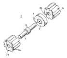
도 1a는 본 발명에 따른 시일의 제 1 실시예의 분해 사시도;1A is an exploded perspective view of a first embodiment of a seal according to the present invention;
도 1b 및 도 1c는 도 1a의 실시예의 일부 구성요소가 조립되어 있는 사시도;1B and 1C are perspective views in which some components of the embodiment of FIG. 1A are assembled;
도 2a 내지 도 2d는, 사용시, 도 1a에 도시된 실시예의 여러 조립 단계를 도시하고 있는 일련의 사시도;2A-2D are a series of perspective views showing various assembly steps of the embodiment shown in FIG. 1A when in use;
도 3은 본 발명의 제 2 실시예의 사시도;3 is a perspective view of a second embodiment of the present invention;
도 4는 도 1a 및 도 2 또는 도 3에 도시된 시일과 함께 사용하기 위한 본 발명의 제 2 양상에 따른 컨테이너를 도시하는 도면이다.4 shows a container according to a second aspect of the invention for use with the seal shown in FIGS. 1a and 2 or 3.
도 1a에 도시된 시일(1)은 고무와 같은 탄성중합체 재료 또는 폴리프로필렌과 같은 강성 재료로 형성된 2개의 지지부재(2a,2b)를 포함한다. 상기 2개의 지지부재(2a,2b)는 서로의 횡방향으로 배치되며, 그들 사이에는 시일링 부재(3)가 삽입된다. 상기 2개의 지지부재(2a,2b)는 폴리프로필렌으로 이루어진 연결부재(4)에 의해 서로 연결된다. 상기 연결부재는 원형의 원통형 로드이며, 지지부재(2a,2b)에 제공된 원형의 원통형 보어구멍(3a,3b)을 통과한다. 상기 연결부재(4)에는 지름이 증가된 영역(6)이 제공되며, 도 1b에 도시된 바와 같이 축방향의 보어구멍(7)에 맞물려 시일링 부재(3)를 지지하게 된다.The
각각 지지부재(2a,2b)에는 당해 지지부재의 원통형 둘레에 방사상으로 배열되어 종방향으로 연장된 다수의 채널(8a,8b)이 제공된다.Each of the supporting
도 2a에 도시된 바와 같이, 광섬유 케이블과 같은 긴 물품(9)이 종방향으로 연장된 채널(8a,8b) 내에 수용될 수 있으며, 서로에 대해 실질적으로 평행하게 배치된다. 상기 시일링 부재(3)의 크기는, 케이블을 대응되는 채널(8a,8b) 내에 수용하기 위하여, 실런트 재료가 케이블에 의해 찌그러지고, 이에 따라 케이블 사이를 시일링하도록, 케이블의 적어도 일부분으로부터 압출되어지는 크기이다.As shown in FIG. 2A, an elongated article 9, such as an optical fiber cable, can be accommodated in longitudinally extending
도 2b에 도시된 바와 같이, 부가적인 유지수단으로서 타이 랩(10)이 시일(1) 상에 배열된 케이블 둘레를 감싸며 설치될 수 있다. 또한, 도 2c에 도시된 바와 같이, 축방향 힘에 대하여 강도를 부가하기 위하여, 축방향 풀 스트립(11)이 시일 상에 배열된 케이블 다발의 둘레를 감싸며 설치될 수 있다. 직경이 큰 구멍 또는 포트에 수용되도록 하기 위해, 겔 테이프(12)와 같은 부가적인 시일링 재료가 변형된 시일링 부재(3)의 둘레를 감싸며 설치될 수 있다.As shown in FIG. 2B, a
도 3에 도시된 제 2 실시예에서, 별도의 연결부재에 의해 상호 연결되는 개별 부품인 상기 제 1 및 제 2 지지부재와는 달리, 제 1 지지부재(13)와 제 2 지지부재(14)는 이들 사이에서 연장된 일체식 상호연결 로드(15)에 의해 일체식 구성요소로서 형성된다. 이러한 일체식 구성요소는 유리하게 폴리프로필렌과 같은 강성 재료로 형성된다.In the second embodiment shown in FIG. 3, unlike the first and second support members, which are separate parts interconnected by separate connecting members, the
전술한 제 1 및 제 2 실시예를 포함하는 본 발명의 시일은 케이블 스플라이스 덮개의 케이블 구멍에 직경이 작은 여러 개의 케이블 둘레를 시일링하는 케이블 시일로서 사용된다. 이러한 케이블 스플라이스 덮개(16)가 도 4에 도시되어 있다. 상기 케이블 스플라이스 덮개(16)는 2개의 하우징 부품(17a,17b)으로 형성되며, 이 하우징 부품은 합체되어 폐쇄 컨테이너를 형성하게 된다. 덮개의 단부는 케이블 구멍(19)을 갖고, 이 구멍은 단부 벽체(18)에 U자형 절개부가 형성된 2개의 하우징 부품(17a,17b)을 합체함으로써 형성된다. 종방향으로 이격된 벽체(20)는 단부 벽체(18)와 함께 캐비티(21)를 형성한다. 시일은, 중앙의 시일링 부재(3)가 캐비티(21) 내에 수용되고, 지지부재(2a,2b 또는 13,14)와, 만약 존재한다면, 축방향 풀 스트립(11)이 벽체(20)의 내측면과 결합되도록, 케이블 구멍(19) 중 어느 하나에 결합된다.The seal of the present invention, which includes the first and second embodiments described above, is used as a cable seal for sealing around a plurality of small diameter cables in a cable hole of a cable splice cover. Such a
Claims (10)
Translated fromKoreanApplications Claiming Priority (2)
| Application Number | Priority Date | Filing Date | Title |
|---|---|---|---|
| GB9814399.3 | 1998-07-03 | ||
| GBGB9814399.3AGB9814399D0 (en) | 1998-07-03 | 1998-07-03 | A seal |
Publications (2)
| Publication Number | Publication Date |
|---|---|
| KR20010074636A KR20010074636A (en) | 2001-08-04 |
| KR100616206B1true KR100616206B1 (en) | 2006-08-25 |
Family
ID=10834866
Family Applications (1)
| Application Number | Title | Priority Date | Filing Date |
|---|---|---|---|
| KR1020017000050AExpired - Fee RelatedKR100616206B1 (en) | 1998-07-03 | 1999-06-15 | seal |
Country Status (19)
| Country | Link |
|---|---|
| US (1) | US6353186B1 (en) |
| EP (1) | EP1095435B1 (en) |
| JP (1) | JP4122136B2 (en) |
| KR (1) | KR100616206B1 (en) |
| CN (1) | CN1169270C (en) |
| AT (1) | ATE273581T1 (en) |
| AU (1) | AU742680B2 (en) |
| BR (1) | BR9911817A (en) |
| CA (1) | CA2337608C (en) |
| DE (1) | DE69919358T2 (en) |
| ES (1) | ES2226396T3 (en) |
| GB (1) | GB9814399D0 (en) |
| IL (1) | IL140215A0 (en) |
| NO (1) | NO327797B1 (en) |
| PL (1) | PL190619B1 (en) |
| RU (1) | RU2001102587A (en) |
| TR (1) | TR200003796T2 (en) |
| WO (1) | WO2000002295A1 (en) |
| ZA (1) | ZA200007408B (en) |
Families Citing this family (48)
| Publication number | Priority date | Publication date | Assignee | Title |
|---|---|---|---|---|
| US7113679B2 (en) | 2000-05-26 | 2006-09-26 | Corning Cable Systems, Llc | Fiber optic drop cables and preconnectorized assemblies having toning portions |
| US7467896B2 (en) | 2000-05-26 | 2008-12-23 | Corning Cable Systems Llc | Fiber optic drop cables and preconnectorized assemblies |
| US9239441B2 (en) | 2000-05-26 | 2016-01-19 | Corning Cable Systems Llc | Fiber optic drop cables and preconnectorized assemblies having toning portions |
| US6583357B2 (en)* | 2001-07-24 | 2003-06-24 | Hewlett-Packard Development Company, L.P. | Cable retention system |
| EP1565776A1 (en)* | 2002-11-30 | 2005-08-24 | Tyco Electronics UK Limited | Sealing device |
| GB0315948D0 (en)* | 2003-07-08 | 2003-08-13 | Tyco Electronics Raychem Nv | Cable splice closure and method of installation therefor |
| GB0321680D0 (en)* | 2003-09-16 | 2003-10-15 | Tyco Electronics Raychem Nv | Improvements in or relating to a protective casing component and an element for forming a protective casing component |
| US7473849B2 (en)* | 2005-04-25 | 2009-01-06 | Cable Components Group | Variable diameter conduit tubes for high performance, multi-media communication cable |
| US7473850B2 (en)* | 2005-04-25 | 2009-01-06 | Cable Components Group | High performance, multi-media cable support-separator facilitating insertion and removal of conductive media |
| US8020811B2 (en)* | 2005-07-07 | 2011-09-20 | Panduit Corp. | Cable bracket and strap assembly |
| US7186929B2 (en)* | 2005-07-08 | 2007-03-06 | 3M Innovative Properties Company | Sealing member for an entry port |
| US20070120023A1 (en)* | 2005-11-29 | 2007-05-31 | Cnh America Llc | Hydraulic hose retention device |
| DE102006007989A1 (en)* | 2006-02-21 | 2007-08-30 | Robert Bosch Gmbh | Electrical plug for use in e.g. rail pressure sensor, has housing, electrical contacts and connecting flange, which are sealed against each other by sealing or adhesive compound provided at housing sides around contacts and flange |
| US7499622B2 (en)* | 2007-02-28 | 2009-03-03 | Corning Cable Systems Llc | Fiber optic drop terminals for multiple dwelling units |
| NO329608B1 (en)* | 2007-11-27 | 2010-11-22 | Nexans | Electric three-phase power cable system |
| US20100139949A1 (en)* | 2008-12-09 | 2010-06-10 | Alfredo Haros Hernandez | Splice wire holder |
| ES2633452T3 (en)* | 2009-12-03 | 2017-09-21 | CommScope Connectivity Belgium BVBA | Gel sealing device |
| EP2339216B1 (en)* | 2009-12-23 | 2012-08-08 | LacTec GmbH | Conduit bushing |
| US8344246B2 (en)* | 2010-04-06 | 2013-01-01 | Google Inc. | Cooling disc for bundles of current carrying cables |
| WO2012058391A1 (en) | 2010-10-28 | 2012-05-03 | Corning Cable Systems Llc | Impact resistant fiber optic enclosures and related methods |
| US9110266B2 (en)* | 2011-07-29 | 2015-08-18 | Corning Cable Systems Llc | Fiber optic cables seal and/or strain relief members, and related assemblies and methods |
| DE102011115521A1 (en)* | 2011-10-11 | 2013-04-11 | Mankiewicz Gebr. & Co. Gmbh & Co Kg | Spacers in cable connection sleeves |
| US8873926B2 (en) | 2012-04-26 | 2014-10-28 | Corning Cable Systems Llc | Fiber optic enclosures employing clamping assemblies for strain relief of cables, and related assemblies and methods |
| US9450389B2 (en) | 2013-03-05 | 2016-09-20 | Yaroslav A. Pichkur | Electrical power transmission system and method |
| DE102014100516B4 (en)* | 2014-01-17 | 2016-01-28 | S-Y Systems Technologies Europe Gmbh | Connecting device and method for producing a cable composite strand |
| WO2016036420A1 (en) | 2014-09-05 | 2016-03-10 | PICHKUR, Dmytro | Transformer |
| CN104181658A (en)* | 2014-09-11 | 2014-12-03 | 成都前宏通讯有限责任公司 | Mechanical sealing locking device for elliptical hole of cable splice closure |
| CN104595585B (en)* | 2014-12-24 | 2017-11-14 | 重庆市瀚德高科机器人有限公司 | A kind of sealing door of pressure vessel wire passing device |
| US9835816B2 (en)* | 2015-06-10 | 2017-12-05 | Telect, Inc. | Fiber blocking kits |
| CN106286530B (en)* | 2016-08-31 | 2018-03-13 | 北京术锐技术有限公司 | A kind of locking device of plurality of rods |
| US12271040B2 (en) | 2017-06-28 | 2025-04-08 | Corning Research & Development Corporation | Fiber optic extender ports, assemblies and methods of making the same |
| US10359577B2 (en) | 2017-06-28 | 2019-07-23 | Corning Research & Development Corporation | Multiports and optical connectors with rotationally discrete locking and keying features |
| CN111051945B (en) | 2017-06-28 | 2023-12-29 | 康宁研究与开发公司 | Compact fiber optic connector, cable assembly and method of making the same |
| US11187859B2 (en) | 2017-06-28 | 2021-11-30 | Corning Research & Development Corporation | Fiber optic connectors and methods of making the same |
| CN111788749B (en)* | 2017-10-18 | 2021-09-28 | 通贝国际有限公司 | Sealant filled cable gland |
| US10481344B2 (en) | 2017-11-21 | 2019-11-19 | Lumentum Operations Llc | High density optical fiber feedthrough |
| EP3830620A1 (en)* | 2018-08-01 | 2021-06-09 | Telefonaktiebolaget LM Ericsson (publ) | Sealing unit for optical fiber cable cabinet |
| WO2020242847A1 (en) | 2019-05-31 | 2020-12-03 | Corning Research & Development Corporation | Multiports and other devices having optical connection ports with sliding actuators and methods of making the same |
| US11294133B2 (en) | 2019-07-31 | 2022-04-05 | Corning Research & Development Corporation | Fiber optic networks using multiports and cable assemblies with cable-to-connector orientation |
| US11536921B2 (en) | 2020-02-11 | 2022-12-27 | Corning Research & Development Corporation | Fiber optic terminals having one or more loopback assemblies |
| US11604320B2 (en) | 2020-09-30 | 2023-03-14 | Corning Research & Development Corporation | Connector assemblies for telecommunication enclosures |
| AU2021368055A1 (en) | 2020-10-30 | 2023-06-08 | Corning Research & Development Corporation | Female fiber optic connectors having a rocker latch arm and methods of making the same |
| US11994722B2 (en) | 2020-11-30 | 2024-05-28 | Corning Research & Development Corporation | Fiber optic adapter assemblies including an adapter housing and a locking housing |
| US11686913B2 (en) | 2020-11-30 | 2023-06-27 | Corning Research & Development Corporation | Fiber optic cable assemblies and connector assemblies having a crimp ring and crimp body and methods of fabricating the same |
| US11880076B2 (en) | 2020-11-30 | 2024-01-23 | Corning Research & Development Corporation | Fiber optic adapter assemblies including a conversion housing and a release housing |
| US11927810B2 (en) | 2020-11-30 | 2024-03-12 | Corning Research & Development Corporation | Fiber optic adapter assemblies including a conversion housing and a release member |
| KR102448205B1 (en)* | 2022-03-03 | 2022-09-28 | 마인엔지니어링건축사사무소 주식회사 | Wire connector for enhanced safety |
| US12129929B1 (en)* | 2024-06-03 | 2024-10-29 | Marco Daniel Iseli | Universal multiple instrumentation gland |
Family Cites Families (8)
| Publication number | Priority date | Publication date | Assignee | Title |
|---|---|---|---|---|
| US3197830A (en)* | 1964-05-01 | 1965-08-03 | Hoadley Robert Bruce | Keeper for electrical cords |
| US4267401A (en)* | 1978-07-03 | 1981-05-12 | Wilkinson William L | Seal plug |
| US4607469A (en)* | 1984-01-03 | 1986-08-26 | Team, Inc. | Seal for water proofing a utility line conduit and a method of forming the seal |
| NL8700204A (en)* | 1987-01-28 | 1988-08-16 | Pidou Bv | SEALING DEVICE. |
| US5245133A (en) | 1991-10-15 | 1993-09-14 | Thomas & Betts Corporation | Moisture-resistant cable splice and sealing structure thereof |
| BR9508857A (en)* | 1994-09-21 | 1997-10-21 | Raychem Sa Nv | Cable joint closure |
| PE69897A1 (en)* | 1996-05-02 | 1997-11-05 | Raychem Sa Nv | CLOSE TO SEAL AN OPENING |
| US6180882B1 (en)* | 1999-01-19 | 2001-01-30 | Thomas & Betts, International | Single and dual cable seal system |
- 1998
- 1998-07-03GBGBGB9814399.3Apatent/GB9814399D0/ennot_activeCeased
- 1999
- 1999-06-15CNCNB998082333Apatent/CN1169270C/ennot_activeExpired - Fee Related
- 1999-06-15RURU2001102587/09Apatent/RU2001102587A/ennot_activeApplication Discontinuation
- 1999-06-15JPJP2000558594Apatent/JP4122136B2/ennot_activeExpired - Fee Related
- 1999-06-15ESES99926613Tpatent/ES2226396T3/ennot_activeExpired - Lifetime
- 1999-06-15ATAT99926613Tpatent/ATE273581T1/ennot_activeIP Right Cessation
- 1999-06-15BRBR9911817-3Apatent/BR9911817A/ennot_activeApplication Discontinuation
- 1999-06-15WOPCT/GB1999/001898patent/WO2000002295A1/enactiveIP Right Grant
- 1999-06-15USUS09/720,501patent/US6353186B1/ennot_activeExpired - Fee Related
- 1999-06-15AUAU43799/99Apatent/AU742680B2/ennot_activeCeased
- 1999-06-15KRKR1020017000050Apatent/KR100616206B1/ennot_activeExpired - Fee Related
- 1999-06-15EPEP99926613Apatent/EP1095435B1/ennot_activeExpired - Lifetime
- 1999-06-15ILIL14021599Apatent/IL140215A0/ennot_activeIP Right Cessation
- 1999-06-15PLPL99344755Apatent/PL190619B1/ennot_activeIP Right Cessation
- 1999-06-15DEDE69919358Tpatent/DE69919358T2/ennot_activeExpired - Lifetime
- 1999-06-15TRTR2000/03796Tpatent/TR200003796T2/enunknown
- 1999-06-15CACA002337608Apatent/CA2337608C/ennot_activeExpired - Fee Related
- 2000
- 2000-12-12ZAZA200007408Apatent/ZA200007408B/enunknown
- 2001
- 2001-01-02NONO20010008Apatent/NO327797B1/ennot_activeIP Right Cessation
Also Published As
| Publication number | Publication date |
|---|---|
| ATE273581T1 (en) | 2004-08-15 |
| WO2000002295A1 (en) | 2000-01-13 |
| GB9814399D0 (en) | 1998-09-02 |
| DE69919358T2 (en) | 2005-09-08 |
| AU742680B2 (en) | 2002-01-10 |
| CA2337608C (en) | 2007-11-20 |
| TR200003796T2 (en) | 2001-07-23 |
| EP1095435A1 (en) | 2001-05-02 |
| IL140215A0 (en) | 2002-02-10 |
| CA2337608A1 (en) | 2000-01-13 |
| JP2002520987A (en) | 2002-07-09 |
| ES2226396T3 (en) | 2005-03-16 |
| NO327797B1 (en) | 2009-09-28 |
| NO20010008L (en) | 2001-01-02 |
| BR9911817A (en) | 2001-03-27 |
| EP1095435B1 (en) | 2004-08-11 |
| NO20010008D0 (en) | 2001-01-02 |
| US6353186B1 (en) | 2002-03-05 |
| CN1308784A (en) | 2001-08-15 |
| AU4379999A (en) | 2000-01-24 |
| JP4122136B2 (en) | 2008-07-23 |
| ZA200007408B (en) | 2002-02-27 |
| PL344755A1 (en) | 2001-11-19 |
| PL190619B1 (en) | 2005-12-30 |
| KR20010074636A (en) | 2001-08-04 |
| DE69919358D1 (en) | 2004-09-16 |
| CN1169270C (en) | 2004-09-29 |
| RU2001102587A (en) | 2003-01-27 |
Similar Documents
| Publication | Publication Date | Title |
|---|---|---|
| KR100616206B1 (en) | seal | |
| RU2186449C2 (en) | Hole packing for object and container | |
| US5675124A (en) | Grommet for a fiber optic enclosure | |
| AU757414B2 (en) | Cable closure | |
| US5886300A (en) | Plug for a sealing grommet | |
| US5556060A (en) | Aerial pedestal below grade or buried optical fiber | |
| CN102197557B (en) | mechanical cable entry | |
| EP2452404B1 (en) | Sealing member | |
| EP0876697A1 (en) | Cable closure | |
| US5783778A (en) | Cable sealing and locking device | |
| AU750371B2 (en) | A seal for a closure and a closure incorporating the seal | |
| US5825960A (en) | Fiber optic management system | |
| WO1997041474A1 (en) | Grommet for a fiber optic enclosure | |
| EP2557442A1 (en) | Cable closure | |
| MXPA00012551A (en) | A seal | |
| US20020062977A1 (en) | Drop cable sealing adapter | |
| CZ20004713A3 (en) | Plug | |
| WO1996009673A1 (en) | Sealing device |
Legal Events
| Date | Code | Title | Description |
|---|---|---|---|
| PA0105 | International application | St.27 status event code:A-0-1-A10-A15-nap-PA0105 | |
| P11-X000 | Amendment of application requested | St.27 status event code:A-2-2-P10-P11-nap-X000 | |
| P13-X000 | Application amended | St.27 status event code:A-2-2-P10-P13-nap-X000 | |
| PG1501 | Laying open of application | St.27 status event code:A-1-1-Q10-Q12-nap-PG1501 | |
| A201 | Request for examination | ||
| P11-X000 | Amendment of application requested | St.27 status event code:A-2-2-P10-P11-nap-X000 | |
| P13-X000 | Application amended | St.27 status event code:A-2-2-P10-P13-nap-X000 | |
| PA0201 | Request for examination | St.27 status event code:A-1-2-D10-D11-exm-PA0201 | |
| E902 | Notification of reason for refusal | ||
| PE0902 | Notice of grounds for rejection | St.27 status event code:A-1-2-D10-D21-exm-PE0902 | |
| T11-X000 | Administrative time limit extension requested | St.27 status event code:U-3-3-T10-T11-oth-X000 | |
| P11-X000 | Amendment of application requested | St.27 status event code:A-2-2-P10-P11-nap-X000 | |
| P13-X000 | Application amended | St.27 status event code:A-2-2-P10-P13-nap-X000 | |
| E701 | Decision to grant or registration of patent right | ||
| PE0701 | Decision of registration | St.27 status event code:A-1-2-D10-D22-exm-PE0701 | |
| PR1002 | Payment of registration fee | St.27 status event code:A-2-2-U10-U12-oth-PR1002 Fee payment year number:1 | |
| GRNT | Written decision to grant | ||
| PR0701 | Registration of establishment | St.27 status event code:A-2-4-F10-F11-exm-PR0701 | |
| PG1601 | Publication of registration | St.27 status event code:A-4-4-Q10-Q13-nap-PG1601 | |
| PR1001 | Payment of annual fee | St.27 status event code:A-4-4-U10-U11-oth-PR1001 Fee payment year number:4 | |
| R18-X000 | Changes to party contact information recorded | St.27 status event code:A-5-5-R10-R18-oth-X000 | |
| PR1001 | Payment of annual fee | St.27 status event code:A-4-4-U10-U11-oth-PR1001 Fee payment year number:5 | |
| FPAY | Annual fee payment | Payment date:20110809 Year of fee payment:6 | |
| PR1001 | Payment of annual fee | St.27 status event code:A-4-4-U10-U11-oth-PR1001 Fee payment year number:6 | |
| LAPS | Lapse due to unpaid annual fee | ||
| PC1903 | Unpaid annual fee | St.27 status event code:A-4-4-U10-U13-oth-PC1903 Not in force date:20120819 Payment event data comment text:Termination Category : DEFAULT_OF_REGISTRATION_FEE | |
| PC1903 | Unpaid annual fee | St.27 status event code:N-4-6-H10-H13-oth-PC1903 Ip right cessation event data comment text:Termination Category : DEFAULT_OF_REGISTRATION_FEE Not in force date:20120819 | |
| PN2301 | Change of applicant | St.27 status event code:A-5-5-R10-R13-asn-PN2301 St.27 status event code:A-5-5-R10-R11-asn-PN2301 |