KR100614638B1 - Hybrid Serial Peripheral Interface Interface Suitable for High-Speed Wireless Communication and Its Method - Google Patents
Hybrid Serial Peripheral Interface Interface Suitable for High-Speed Wireless Communication and Its MethodDownload PDFInfo
- Publication number
- KR100614638B1 KR100614638B1KR20030012069AKR20030012069AKR100614638B1KR 100614638 B1KR100614638 B1KR 100614638B1KR 20030012069 AKR20030012069 AKR 20030012069AKR 20030012069 AKR20030012069 AKR 20030012069AKR 100614638 B1KR100614638 B1KR 100614638B1
- Authority
- KR
- South Korea
- Prior art keywords
- data
- transmission
- slave
- transmission rate
- transmitted
- Prior art date
- Legal status (The legal status is an assumption and is not a legal conclusion. Google has not performed a legal analysis and makes no representation as to the accuracy of the status listed.)
- Expired - Fee Related
Links
Images


Classifications
- H—ELECTRICITY
- H04—ELECTRIC COMMUNICATION TECHNIQUE
- H04L—TRANSMISSION OF DIGITAL INFORMATION, e.g. TELEGRAPHIC COMMUNICATION
- H04L12/00—Data switching networks
- H04L12/64—Hybrid switching systems
- H—ELECTRICITY
- H04—ELECTRIC COMMUNICATION TECHNIQUE
- H04W—WIRELESS COMMUNICATION NETWORKS
- H04W28/00—Network traffic management; Network resource management
- H04W28/16—Central resource management; Negotiation of resources or communication parameters, e.g. negotiating bandwidth or QoS [Quality of Service]
- H04W28/18—Negotiating wireless communication parameters
- H—ELECTRICITY
- H04—ELECTRIC COMMUNICATION TECHNIQUE
- H04L—TRANSMISSION OF DIGITAL INFORMATION, e.g. TELEGRAPHIC COMMUNICATION
- H04L9/00—Cryptographic mechanisms or cryptographic arrangements for secret or secure communications; Network security protocols
- H04L9/40—Network security protocols
- H—ELECTRICITY
- H04—ELECTRIC COMMUNICATION TECHNIQUE
- H04L—TRANSMISSION OF DIGITAL INFORMATION, e.g. TELEGRAPHIC COMMUNICATION
- H04L69/00—Network arrangements, protocols or services independent of the application payload and not provided for in the other groups of this subclass
- H04L69/30—Definitions, standards or architectural aspects of layered protocol stacks
- H04L69/32—Architecture of open systems interconnection [OSI] 7-layer type protocol stacks, e.g. the interfaces between the data link level and the physical level
- H04L69/322—Intralayer communication protocols among peer entities or protocol data unit [PDU] definitions
- H04L69/324—Intralayer communication protocols among peer entities or protocol data unit [PDU] definitions in the data link layer [OSI layer 2], e.g. HDLC
- H—ELECTRICITY
- H04—ELECTRIC COMMUNICATION TECHNIQUE
- H04W—WIRELESS COMMUNICATION NETWORKS
- H04W28/00—Network traffic management; Network resource management
- H04W28/02—Traffic management, e.g. flow control or congestion control
- H04W28/06—Optimizing the usage of the radio link, e.g. header compression, information sizing, discarding information
- H—ELECTRICITY
- H04—ELECTRIC COMMUNICATION TECHNIQUE
- H04W—WIRELESS COMMUNICATION NETWORKS
- H04W28/00—Network traffic management; Network resource management
- H04W28/16—Central resource management; Negotiation of resources or communication parameters, e.g. negotiating bandwidth or QoS [Quality of Service]
- H04W28/18—Negotiating wireless communication parameters
- H04W28/22—Negotiating communication rate
- H—ELECTRICITY
- H04—ELECTRIC COMMUNICATION TECHNIQUE
- H04W—WIRELESS COMMUNICATION NETWORKS
- H04W84/00—Network topologies
- H04W84/02—Hierarchically pre-organised networks, e.g. paging networks, cellular networks, WLAN [Wireless Local Area Network] or WLL [Wireless Local Loop]
- H04W84/10—Small scale networks; Flat hierarchical networks
- H04W84/12—WLAN [Wireless Local Area Networks]
Landscapes
- Engineering & Computer Science (AREA)
- Computer Networks & Wireless Communication (AREA)
- Signal Processing (AREA)
- Computer Security & Cryptography (AREA)
- Quality & Reliability (AREA)
- Communication Control (AREA)
- Mobile Radio Communication Systems (AREA)
- Information Transfer Systems (AREA)
- Small-Scale Networks (AREA)
Abstract
Translated fromKoreanDescription
Translated fromKorean도 1은 본 발명에 따른 무선 랜용 전자 장치의 일부 구성을 개략적으로 나타내는 블럭도;1 is a block diagram schematically showing some components of an electronic device for a wireless LAN according to the present invention;
도 2는 일반적인 무선랜용 전자 장치의 미디어 억세스 컨트롤러와 베이스밴드 프로세서 간의 데이터 전송시 임계 시점을 나타내는 타이밍도;FIG. 2 is a timing diagram illustrating a threshold time point during data transmission between a media access controller and a baseband processor in a typical WLAN electronic device. FIG.
도 3은 본 발명에 따른 무선랜용 전자 장치의 미디어 억세스 컨트롤러와 베이스밴드 프로세서 간의 데이터 전송시 임계 시점을 맞추기 위한 셋 어헤드(set-ahead) 기능을 설명하기 위한 타이밍도;FIG. 3 is a timing diagram illustrating a set-ahead function for matching a threshold time point during data transmission between a media access controller and a baseband processor of an electronic device for a wireless LAN according to the present invention; FIG.
도 4는 도 1에 도시된 직렬 주변장치 인터페이스 회로의 상세한 구성을 도시한 블럭도;4 is a block diagram showing a detailed configuration of the serial peripheral interface circuit shown in FIG.
도 5는 도 4에 도시된 유한 상태 머신의 하드웨어 자동 동작 제어 방식을 나타내는 도면;FIG. 5 shows a hardware automatic motion control scheme of the finite state machine shown in FIG. 4; FIG.
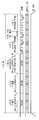
도 6a는 도 4에 도시된 직렬 주변장치 인터페이스 회로로부터 베이스밴드 프로세서로 전송 속도 데이터를 전송하기 위한 타이밍도; 그리고FIG. 6A is a timing diagram for transferring baud rate data from the serial peripheral interface circuit shown in FIG. 4 to the baseband processor. FIG. And
도 6b는 도 4에 도시된 직렬 주변장치 인터페이스 회로로부터 베이스밴드 프 로세서로 전송 길이 데이터를 전송하기 위한 타이밍도이다.6B is a timing diagram for transferring transmission length data from the serial peripheral interface circuit shown in FIG. 4 to the baseband processor.
* 도면의 주요 부분에 대한 부호 설명 *Explanation of symbols on the main parts of the drawings
10 : 무선 랜용 전자 장치20 : 미디어 억세스 컨트롤러10: electronic device for wireless LAN 20: media access controller
30 : 베이스밴드 프로세서40 : 외부 메모리 장치30: baseband processor 40: external memory device
100 : SPI 회로102 : SPI 컨트롤러100: SPI circuit 102: SPI controller
104 : 제어 레지스터106 : 타이머104: control register 106: timer
108 : 데이터 변환부110 : 멀티플렉서108: data converter 110: multiplexer
112 : 전송전송 속도 데이터 제어부114 : 전송전송 길이 데이터 제어부112: transmission transmission speed data control unit 114: transmission transmission length data control unit
116 : 수신 데이터 버퍼118 : 송신 데이터 버퍼116: receive data buffer 118: transmit data buffer
120 : 클럭 제너레이터122 : 데이터 쉬프터120: clock generator 122: data shifter
130 : 유한 상태 머신(FSM)S0 ~ S12 : 상태(State)130: Finite state machine (FSM) S0 ~ S12: State
본 발명은 데이터 전송 장치에 관한 것으로, 좀 더 구체적으로는 데이터 전송 장치내 마스터와 슬레이브 간의 직렬 주변 장치 인터페이스(Serial Peripheral Interface : SPI)를 통한 데이터 전송에 관한 것이다.The present invention relates to a data transmission device, and more particularly, to data transmission through a serial peripheral interface (SPI) between a master and a slave in a data transmission device.
또한, 본 발명은 무선 랜(Wireless LAN) 환경 하에서의 동작하는 데이터 전송 장치의 직렬 주변 장치 인터페이스(Serial Peripheral Interface : SPI) 회로에 관한 것이다.The present invention also relates to a serial peripheral interface (SPI) circuit of a data transmission device operating in a wireless LAN environment.
미디어 억세스 컨트롤러(Media Access Controller : MAC)와 베이스밴드 프로세서(BaseBand processor : BBP)는 상호 데이터 통신을 위해서 직렬 주변장치 인터페이스(SPI)를 구비하고, 정보의 요청, 전송 및 수신 확인 등의 신호를 주고받는 핸드쉐이킹 방식(handshaking)을 이용하여 상호 데이터 통신을 수행한다.The Media Access Controller (MAC) and the BaseBand Processor (BBP) are equipped with a Serial Peripheral Interface (SPI) for data communication with each other and provide signals for requesting, transmitting and receiving information. Receive handshaking (handshaking) to perform mutual data communication.
일반적으로 직렬 주변장치 인터페이스(SPI)는 동기식 직렬 통신 방식으로 저속의 제어가 필요한 전자 장치에 사용하기 적합한 통신 프로토콜이다. 또한 상기 SPI는 저속의 통신에 이용되기 때문에 이들 전자 장치들은 소프트웨어 제어 방식을 이용하여 직렬 주변장치 인터페이스를 제어한다.In general, serial peripheral interface (SPI) is a synchronous serial communication method that is suitable for use in electronic devices requiring low speed control. In addition, since the SPI is used for low speed communication, these electronic devices use a software control method to control the serial peripheral interface.
그러나 무선 랜(WLAN) 환경과 같이 고속 통신이 필요한 시스템 내의 마스터와 슬레이브 간에 직렬 주변장치 인터페이스(SPI)를 이용하여 통신을 수행하는 경우, 종래에는 소프트웨어 제어 방식만으로 처리하여 데이터 전송시 프레임들 간의 임계 시점(critical timing)을 정확히 맞추지 못함으로써, 통신 장애가 발생하게 된다.However, when performing communication using a serial peripheral interface (SPI) between a master and a slave in a system requiring high speed communication, such as a wireless LAN (WLAN) environment, it is conventionally processed only by a software control method and thus the threshold between frames in data transmission. Incorrect timing can lead to communication failures.
본 발명의 목적은 상술한 문제점을 해결하기 위한 것으로, 고속의 무선 통신을 수행하는 데이터 전송 장치 내 마스터와 슬레이브 간의 새로운 직렬 주변 장치 인터페이스 회로를 제공하는데 있다.SUMMARY OF THE INVENTION An object of the present invention is to solve the above problems, and to provide a new serial peripheral interface circuit between a master and a slave in a data transmission device that performs high-speed wireless communication.
본 발명의 다른 목적은 상술한 문제점을 해결하기 위한 것으로, 고속의 무선 통신을 수행하는 데이터 전송 장치 내 직렬 주변 장치 인터페이스의 데이터 전송 방법을 구현하는데 있다.Another object of the present invention is to solve the above-described problem, and to implement a data transmission method of a serial peripheral interface in a data transmission device that performs high-speed wireless communication.
상술한 목적을 달성하기 위한 본 발명의 특징에 의하면, 마스터와 슬레이브 간에 직렬 데이터 통신 인터페이스를 이용하여 상호 데이터 통신을 수행하는 데이터 전송 장치는, 상기 마스터로부터 상기 슬레이브로 전송할 데이터에 대한 전송 속도 데이터 및 전송 길이 데이터를 각각 받아들이는 데이터 입력부들과, 상기 데이터 입력부들로부터 상기 전송 속도 데이터 및 상기 전송 길이 데이터를 받아들이고, 외부로부터 상기 전송 속도 데이터 및/또는 상기 전송 길이 데이터를 상기 슬레이브로 전송하도록 하는 제 1 및/또는 제 2 이벤트 신호를 받아서 상기 전송 속도 데이터 및/또는 상기 전송 길이 데이터를 선택적으로 출력하는 선택부와, 상기 선택부로부터 상기 전송할 데이터를 받아서 직렬 데이터 통신 인터페이스를 이용하여 상기 슬레이브로 전송하도록 제어하는 컨트롤러 및 상기 이벤트 신호가 적어도 하나 발생되면, 상기 전송할 데이터의 프레임 전송시, 상기 전송 속도 데이터 및/또는 상기 전송 길이 데이터를 상기 슬레이브가 워밍업하는 구간 내에 전송하여 임계 시점을 조절하도록 자동 제어하는 제어부를 포함한다.According to an aspect of the present invention for achieving the above object, a data transmission apparatus for performing mutual data communication using a serial data communication interface between a master and a slave, the transmission rate data for the data to be transmitted from the master to the slave and A data input unit for receiving transmission length data, and receiving the transmission rate data and the transmission length data from the data input units, and transmitting the transmission rate data and / or the transmission length data from the outside to the slave. A selection unit that receives a first and / or second event signal and selectively outputs the transmission rate data and / or the transmission length data, and receives the transmission data from the selection unit and transmits the transmission data to the slave using a serial data communication interface. When at least one controller and the event signal are generated, when the frame is transmitted, the transmission rate data and / or the transmission length data are transmitted within a period where the slave warms up to automatically adjust a threshold time point. It includes a control unit.
이 특징의 바람직한 실시예에 있어서, 상기 입력부는 상기 전송 속도 데이터를 받아들이는 제 1 데이터 입력부와, 상기 전송 길이 데이터를 받아들이는 제 2 전송 데이터 입력부를 포함하되, 상기 제 1/제 2 데이터 입력부는 상기 제 1/제 2 이벤트 신호가 발생되면, 상기 제어부의 제어를 받아서 상기 선택부로 출력한다.In a preferred embodiment of this aspect, the input section includes a first data input section for receiving the transmission rate data and a second transmission data input section for receiving the transmission length data, wherein the first / second data input section includes: When the first / second event signal is generated, the controller outputs the signal to the selection unit under the control of the controller.
이 특징의 바람직한 실시예에 있어서, 상기 선택부는 멀티플렉서로 구비된다.In a preferred embodiment of this feature, the selector is provided as a multiplexer.
이 특징의 바람직한 실시예에 있어서, 상기 컨트롤러는, 직렬 데이터 통신 인터페이스를 위한 정보들을 설정하는 다수의 플래그를 구비하는 제어 레지스터와, 상기 전송 속도 데이터와 상기 전송 길이 데이터를 연속해서 전송할 경우, 상기 제어부의 제어를 받아서 상기 슬레이브와 연계 동작이 이루어지도록 상기 데이터들 간의 적정의 지속 시간을 설정하기 위한 타이머 및 상기 제어부의 제어를 받아서 상기 전송 길이 데이터를 상기 슬레이브의 데이터로 변환하는 데이터 변환부를 구비한다.In a preferred embodiment of this aspect, the controller includes a control register having a plurality of flags for setting information for a serial data communication interface, and the control unit when continuously transmitting the transmission rate data and the transmission length data. And a timer for setting an appropriate duration between the data to perform the cooperative operation with the slave under control of the controller, and a data converter for converting the transmission length data into data of the slave under the control of the controller.
이 실시예에 있어서, 상기 데이터 변환부는 데이터 량을 시간 단위의 데이터로 변환하는 것이 바람직하다.In this embodiment, the data converter preferably converts the data amount into data in units of time.
이 특징의 바람직한 실시예에 있어서, 상기 제 1 및 제 2 이벤트 신호는 외부에 구비되는 메모리 장치에 저장된 펌웨어로부터 발생되며, 상기 슬레이브로부터 데이터 수신시, 상기 펌웨어가 상기 프레임의 헤더로부터 전송된 프레임에 대한 응답 프레임을 전송할 필요가 있는지를 판별하거나, 또는 상기 펌웨어 사용자의 요구에 의해서 발생된다.In a preferred embodiment of this aspect, the first and second event signals are generated from firmware stored in an externally provided memory device, and upon receiving data from the slave, the firmware is transmitted to a frame transmitted from a header of the frame. Whether a response frame needs to be transmitted or generated at the request of the firmware user.
이 특징의 바람직한 실시예에 있어서, 상기 제어부는 유한 상태 머신으로 구비된다. 상기 제어부는 상기 전송 속도 데이터와 상기 전송 길이 데이터를 연속해서 전송할 경우, 상기 전송 속도 데이터를 미리 전송한다. 이 경우, 상기 제어부는 바로 직전에 전송된 프레임의 전송 속도와 동일한 전송 속도 데이터로 전송하는 것이 바람직하다.In a preferred embodiment of this aspect, the control unit is provided with a finite state machine. The control unit transmits the transmission rate data in advance when the transmission rate data and the transmission length data are continuously transmitted. In this case, the control unit preferably transmits data at the same transmission rate data as that of the immediately transmitted frame.
이 특징의 바람직한 실시예에 있어서, 상기 제어부는 상기 이벤트 신호가 적어도 하나 발생되면, 해당 이벤트 신호에 응답해서 상기 전송 속도 데이터와 상기 전송 길이 데이터를 상기 슬레이브로 연속해서 전송하도록 제어하는 제 1의 제어 상태들 및 상기 전송 속도 데이터와 상기 전송 길이 데이터들 중 하나만 상기 슬레이브로 전송하도록 제어하는 제 2 또는 제 3의 제어 상태들을 포함한다.In a preferred embodiment of the present invention, the control unit controls the first control to continuously transmit the transmission rate data and the transmission length data to the slave in response to the event signal when at least one event signal is generated. States and second or third control states that control to transmit only one of the transmission rate data and the transmission length data to the slave.
이 때, 상기 제어부는 상기 전송 속도 데이터와 상기 전송 길이 데이터를 연속해서 전송하는 경우, 상기 타이머의 상기 지속 시간에 대응해서 상기 슬레이브의 선택하는 신호를 활성화시키고, 상기 전송 길이 데이터를 전송시, 상기 전송 길이 데이터를 바이트 단위의 데이터에서 마이크로 세컨드 단위의 데이터로 변환하여 전송하는 것이 바람직하다.In this case, when the transmission rate data and the transmission length data are continuously transmitted, the controller activates a signal selected by the slave in response to the duration of the timer, and when transmitting the transmission length data, It is preferable to convert the transmission length data from data in bytes to data in microseconds.
이 특징의 바람직한 실시예에 있어서, 상기 제어부는 상기 임계 시점을 조절하기 위한 하드웨어 인터럽트 발생 또는 소프트웨어 폴링 방식으로 상기 전송할 데이터의 프레임 전송 상태를 체크하도록 하는 소프트웨어로 구비될 수 있다.In a preferred embodiment of this aspect, the control unit may be provided with software for checking the frame transmission state of the data to be transmitted in a hardware interrupt generation or software polling method for adjusting the threshold time.
이 특징의 바람직한 실시예에 있어서, 상기 데이터 전송 장치는 무선 랜용 전자 장치에 구비되는 것이 적합하다.In a preferred embodiment of this aspect, the data transmission device is suitably provided in the electronic device for wireless LAN.
따라서 본 발명에 의하면, 하이브리드 형 데이터 전송 장치는 기본적으로 소프트웨어 제어 방식에 의해 동작하도록 준비 상태에 있다가 무선 랜 펌웨어에 의해 베이스밴드 프로세서로 전송 데이터의 전송 속도 데이터와 전송 길이 데이터를 기입하는 적어도 하나의 이벤트 신호를 입력받게 되면, 유한 상태 머신의 동작 수순에 따라 하드웨어 자동 제어 방식으로 동작한다. 이 때, 전송 속도 데이터와 전송 길이 데이터를 모두 전송시에 이들을 분리하고, 전송 속도 데이터는 미리 전송하는 셋 어헤드(Set-ahead) 기능을 이용한다Therefore, according to the present invention, at least one of the hybrid data transmission apparatus is basically ready to operate by a software control scheme and writes transmission rate data and transmission length data of the transmission data to the baseband processor by the WLAN firmware. When the event signal is received, it operates by the hardware automatic control method according to the operation procedure of the finite state machine. In this case, a set-ahead function is used in which both transmission rate data and transmission length data are separated at the time of transmission, and transmission rate data is transmitted in advance.
이하 본 발명의 실시예를 첨부된 도면에 의거하여 상세히 설명한다.DETAILED DESCRIPTION Hereinafter, embodiments of the present invention will be described in detail with reference to the accompanying drawings.
도 1은 본 발명에 따른 무선 랜용 전자 장치의 일부 구성을 도시한 블럭도이다.1 is a block diagram illustrating some components of an electronic device for a wireless LAN according to the present invention.
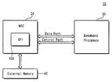
도면을 참조하면, 상기 전자 장치(10)는 미디어 억세스 컨트롤러(Media Access Controller : MAC)(20)와 베이스밴드 프로세서(BaseBand Processor : BBP)(30) 및 외부 메모리 장치(External Memory)(40)를 포함한다. 상기 전자 장치(10)는 고속의 무선 랜 프로토콜을 이용하여 데이터 통신을 수행하는 예를 들어, PDA 등의 모바일 장치와, 무선 랜용 네트워크 카드 및 외장형 모뎀 등과 같은 박스(box) 형 어플리케이션 등이 있다.Referring to the drawings, the
상기 미디어 억세스 컨트롤러(MAC)(20)는 무선 랜용 데이터 통신에 적합한 디바이스로, 신규한 직렬 주변장치 인터페이스(Serial Perripheral Interface : SPI) 회로(100)를 구비한다.The media access controller (MAC) 20 is a device suitable for data communication for a wireless LAN and includes a novel serial peripheral interface (SPI)
상기 베이스밴드 프로세서(BBP)(30)는 예컨대, 상기 전자 장치(10)의 RF/IF 트랜시버(미도시됨)와 상기 미디어 억세스 컨트롤러(20) 사이에 구비되어 송수신되는 데이터를 변복조하여 출력한다.The baseband processor (BBP) 30 modulates and outputs data transmitted and received between, for example, an RF / IF transceiver (not shown) of the
그리고 상기 외부 메모리 장치(40)는 상기 미디어 억세스 컨트롤러(MAC)(20) 외부에 구비되며 상기 전자 장치(10)의 용도에 따른 펌웨어(firmware), 오퍼레이팅 시스템(OS) 및 응용 프로그램 등의 소프트웨어를 저장한다.The
따라서 상기 미디어 억세스 컨트롤러(MAC)(20)는 무선 랜(WLAN) 환경에서 베이스밴드 프로세서(BBP)(30)와 상호 데이터 및 제어 신호를 전송하기 위한 데이터 패스(Data Path) 및 제어 신호 패스(Control Path)를 구비한다. 그리고 상기 미디어 억세스 컨트롤러(MAC)(20)는 외부 메모리(40)에 저장된 데이터 및 제어 신호들을 받아들여서 상기 전자 장치(10)의 펌웨어(firmware), 오퍼레이팅 시스템(OS) 및/또는 응용 프로그램 등의 처리 수순에 대응하는 제어 동작을 수행한다.Accordingly, the media access controller (MAC) 20 controls a data path and a control signal path for transmitting data and control signals to and from the baseband processor (BBP) 30 in a wireless LAN (WLAN) environment. Path). The media access controller (MAC) 20 accepts data and control signals stored in the
상기 데이터 패스는 상기 미디어 억세스 컨트롤러(MAC)(20)와 상기 베이스밴드 프로세서(BBP)(30) 간의 데이터 전송 경로로서, 데이터 전송량에 따라 비트 직렬(bit-serial) 방식 또는 바이트 병렬(byte-parallel) 방식 등으로 구분된다. 상기 제어 패스는 베이스밴드 프로세서(BBP)(30)에 구비되는 레지스터(미도시됨)를 독출, 기입하기 위한 경로로, 직렬 주변장치 인터페이스(SPI)나 IOM-2 인터페이스(ISDN Oriented Modular Interface) 또는 메모리 컨트롤러 인터페이스 등을 사용한다. 그런데 제어 패스를 통해 전송되는 정보는 일반적으로 레지스터의 초기화나 현재 상태를 점검하는 정보들이지만, 필요에 따라 매 전송 데이터마다 전달해야 하는 정보가 포함된다. 이러한 정보로는 전송할 프레임의 전송 속도 데이터(TX Rate)와 전송 데이터의 전송 길이 데이터(TX Length) 등이 있다.The data path is a data transmission path between the media access controller (MAC) 20 and the baseband processor (BBP) 30, and is a bit-serial method or byte-parallel depending on the amount of data transmission. ) And the like. The control path is a path for reading and writing a register (not shown) included in the baseband processor (BBP) 30. The control path is a serial peripheral interface (SPI) or an IOM-2 interface (ISDN Oriented Modular Interface). Use a memory controller interface. By the way, the information transmitted through the control path is generally information that checks the initialization or the current state of the register, but includes information that must be transmitted for each transmission data as necessary. Such information may include transmission rate data (TX rate) of a frame to be transmitted and transmission length data (TX Length) of transmission data.
상기 직렬 주변장치 인터페이스(SPI) 회로(100)는 본 발명에 따른 소프트웨어 제어 방식 및 하드웨어 자동 제어 방식으로 처리하는 하이브리드(hybrid) 형 인터페이스 장치이다. 상기 SPI 회로(100)는 무선 랜 환경에서 전송되는 프레임 간 의 임계 시점(critical timing)을 정확히 조절하기 위하여 하드웨어 자동 제어 방식으로 제어한다.The serial peripheral interface (SPI)
무선 랜 환경에서의 프레임 전송은 유선 랜 환경과 대비하여 채널 특성이 좋지 않기 때문에, 매 프레임마다 수신 확인용 승인(acknowledgment : ACK) 프레임을 전송해야 한다. 즉, 수신측 스테이션(station : STA)은 데이터가 정상적으로 수신되면, 승인(ACK) 프레임을 송신측 스테이션(STA)으로 전송하여 수신 상태의 정상 여부를 알려준다.Frame transmission in a wireless LAN environment has poor channel characteristics compared to a wired LAN environment, and therefore, an acknowledgment (ACK) frame must be transmitted every frame. That is, when data is normally received, the receiving station (station) transmits an acknowledgment (ACK) frame to the transmitting station (STA) to inform whether the reception state is normal.
그런데 무선 랜 환경에서 데이터 수신 후, 승인(ACK) 프레임을 전송해야 하는데 사용되는 시간 간격(time interval)은 SIFS(Short Inter-Frame Space)로서 매우 짧은 간격이다. 시간 간격은 인터프레임 스페이스(Inter-Frame Space : IFS)라 칭하는, 전송되는 프레임들 사이의 시간 간격으로, 우선 순위에 의하여 프레임 간격이나 재전송 간격 등에 차이를 두어 제어한다. SIFS는 승인(ACK) 프레임, CTS(Clear To Send) 프레임 및 세그멘트된 데이터 프레임의 버스트(burst) 전송 등의 동작에 대응하여 즉각적인 응답을 하기 위하여 사용된다.However, after receiving data in a wireless LAN environment, an acknowledgment (ACK) frame should be transmitted. The time interval used is a short inter-frame space (SIFS), which is a very short interval. The time interval is a time interval between transmitted frames, called an inter-frame space (IFS), and is controlled based on a difference in frame interval or retransmission interval according to priority. SIFS is used for immediate response in response to operations such as acknowledgment (ACK) frames, clear to send (CTS) frames, and burst transmission of segmented data frames.
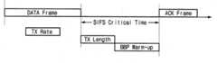
따라서 도 2에 도시된 바와 같이, SIFS의 짧은 간격 내에 전송 데이터의 전송 속도 데이터(TX Rate)와 전송 길이 데이터(TX Length)를 전달하고, 베이스밴드 프로세서를 워밍업(warm-up)시키는 동작은 매우 조절이 어려워 베이스밴드 프로세서의 워밍업 타이밍(BBP Warm-up)이 임계 시점을 지나치게 되는 경우가 빈번하다. 특히, 소프트웨어 제어 방식의 직렬 주변장치 인터페이스(SPI)를 이용하여 데이터 프레임(DATA Frame)과 승인 프레임(ACK Frame) 간의 SIFS 동안, 전송 데이터의 전송 속도 데이터(TX Rate)와 전송 길이 데이터(TX Length)를 전달하고 베이스밴드 프로세서를 워밍업(BBP Warm-up)하는 경우에는 SIFS의 임계 시간(Critical Time)을 정확히 맞출 수가 없다.Therefore, as shown in FIG. 2, the operation of transferring the transmission rate data (TX rate) and transmission length data (TX Length) of transmission data within a short interval of SIFS, and warming up the baseband processor is very difficult. Difficult adjustments often cause the baseband processor's warm-up timing to go beyond the critical point. In particular, during the SIFS between the data frame and the acknowledgment frame using the software-controlled serial peripheral interface (SPI), the transmission rate data (TX rate) and transmission length data (TX Length) of the transmission data ), And the BBP warm-up of the baseband processor does not accurately match the critical time of the SIFS.
그 이유는 소프트웨어 제어 방식의 SPI는 데이터의 송수신 동작시 소프트웨어가 폴링(polling)하는 방식으로 매 동작을 제어하는데, 소프트웨어 제어 방식은 동작 시간에 대한 예측이 정확하지 못할 뿐만 아니라, 일반적으로 많은 시간이 소요된다. 또한 SPI는 저속의 통신에 적합한 인터페이스로 개발되어서 SPI 자체의 전송 속도가 낮기 때문이다.The reason is that the software-controlled SPI controls every operation by the software polling during data transmission and reception. It takes In addition, SPI is developed as an interface suitable for low-speed communication, so the transmission rate of the SPI itself is low.
따라서 본 발명의 하이브리드형 SPI 회로는 상술한 문제점들을 해결하기 위하여 다음의 2 가지 기능을 구비한다.Accordingly, the hybrid SPI circuit of the present invention has the following two functions in order to solve the above problems.
첫째, 전송 데이터의 전송 길이 데이터와 전송 속도 데이터를 제어하는 부분은 하드웨어적으로 자동 제어한다. 즉, 기존의 소프트웨어가 제어하는 부분을 유한 상태 머신으로 자동 제어함으로써, 시간 예측이 정확하지 못한 점을 해결한다.First, the part controlling the transmission length data and the transmission rate data of the transmission data is automatically controlled by hardware. In other words, by automatically controlling the part controlled by the existing software with a finite state machine, the time prediction is corrected.
둘째, 비록 하드웨어적로 제어한다고 할지라도 SPI 자체의 속도가 느리므로 데이터 프레임 수신 후에, 전송할 데이터의 전송 길이 데이터와 전송 속도 데이터를 전송하는 것은 프레임 간의 임계 시점을 정확히 맞출 수가 없다. 따라서 도 3에 도시된 바와 같이, 전송 데이터의 전송 길이 데이터와 전송 속도 데이터를 분리하여 전송 속도 데이터는 미리 전송하는 방식(이하 '셋 어헤드(Set-ahead)' 기능이라 한다)을 사용한다. 이 때, 셋 어헤드 기능은 전송 데이터의 전송 속도 데이터를 바로 직전 송신 프레임의 전송 속도 데이터와 동일한 전송 속도로 전송함으로써 통신 채널을 충분히 활용할 수 있다.Second, even if the hardware control, since the speed of the SPI itself is slow, after transmitting the data frame, transmitting the transmission length data and the transmission rate data of the data to be transmitted cannot accurately match the critical time point between the frames. Therefore, as shown in FIG. 3, the transmission length data of the transmission data and the transmission rate data are separated, and thus the transmission rate data is transmitted in advance (hereinafter, referred to as a “set-ahead” function). At this time, the set-head function can fully utilize the communication channel by transmitting the transmission rate data of the transmission data at the same transmission rate as the transmission rate data of the immediately preceding transmission frame.
구체적으로 도 4는 도 1에 도시된 직렬 주변장치 인터페이스 회로의 상세한 구성을 도시한 블럭도이다.Specifically, FIG. 4 is a block diagram showing a detailed configuration of the serial peripheral interface circuit shown in FIG.
도면을 참조하면, 상기 SPI 회로(100)는 신규한 SPI 컨트롤러(102)와, 유한 상태 머신(Finite State Machine : FSM)(130)과, 제 1 및 제 2 데이터 입력부(112, 114) 및 멀티플렉서(110)를 포함한다. 그리고 상기 SPI 회로(100)는 송수신 데이터 버퍼(116, 118)와, 데이터 쉬프터(122) 및 클럭 발생부(120)를 포함한다.Referring to the drawings, the
상기 SPI 회로(100)는 SPI의 전형적인 소프트웨어 제어 방식에서 필요한 기본 입출력 신호들 예컨대, 소프트웨어 제어 신호(Control_SW), SPI 클럭 신호(SPICLK), MISO(Master In Slave Out), MOSI(Master Out Slave In) 및 SPI 칩선택 신호(SPICS) 등을 포함한다. 예를 들어, SPI 회로(100)는 마스터(master)인 미디어 억세스 컨트롤러(20)와, 슬레이브(slave)인 베이스밴드 프로세서(30) 간의 데이터 통신시, SPI 클럭 신호(SPICLK)가 마스터 모드(master mode)에서는 출력용 클럭 신호로, 슬레이브 모드(slave mode)에서는 입력용 클럭 신호로 동작된다.The
또한 상기 SPI 회로(100)는 본 발명에 따른 하드웨어 자동 제어 방식에 의해서 동작하기 위하여, 기본적으로 필요한 상술한 입출력 신호 외에도 외부 메모리 장치(40)에 저장된 무선 랜 펌웨어로부터 전송 속도 데이터와, 전송 데이터의 전송 길이 데이터를 전송하는 제 1 및 제 2 데이터 신호(TX Rate, TX Length)와, 이들을 베이스밴드 프로세서(30)에 전송하도록 하는 제 1 및 제 2 이벤트 신호들(ES_TXRate, ES_TXLength)을 포함한다.In addition to the above-described input and output signals necessary for the
상기 제 1 데이터 입력부(112)는 외부 메모리(40)로부터 전송 데이터의 전송 속도 데이터(TX Rate)를 받아서 저장하고, 전송 속도 데이터(TX Rate)를 전송하기 위한 제 1 이벤트 신호(ES_TXRate)가 활성화되면, 상기 유한 상태 머신(130)의 제어를 받아서 상기 멀티플렉서(110)로 출력한다.The first
상기 제 2 데이터 입력부(114)는 외부 메모리(40)로부터 전송 데이터의 전송 길이 데이터(TX Length)를 받아서 저장하고, 전송 길이 데이터(TX Length)를 전송하기 위한 제 2 이벤트 신호(ES_TXLength)가 활성화되면, 상기 유한 상태 머신(130)의 제어를 받아서 상기 멀티플렉서(110)로 출력한다.The second
상기 멀티플렉서(110)는 펌웨어로부터 제 1 및 제 2 이벤트 신호들(ES_TXRate, ES_TXLength)을 받아서 소프트웨어 제어 신호(Control_SW)와, 제 1 및 제 2 데이터(TX Rate, TX Length)들 중에 해당 이벤트 신호에 적합한 데이터를 상기 SPI 컨트롤러(102)로 출력한다.The
상기 SPI 컨트롤러(102)는 내부에 제어 레지스터(104)와, 타이머(106) 및 데이터 변환부(108)를 구비한다. 상기 제어 레지스터(102)는 SPI 인에이블, SPI 마스터/슬레이브 모드 선택, 클럭 극성(polarity), 클럭 위상(phase), 클럭 속도, 인터럽트 인에이블, 전송 종료 등의 값들을 설정하는 플래그들을 구비한다. 상기 타이머(106)는 전송될 프레임들 간의 적정의 지연 구간(duration)을 설정하기 위하여 시간을 계산한다. 따라서 전송 속도(TX Rate)와 전송 데이터의 전송 길이 데이터(TX Length)를 연속해서 전송할 경우, 전송 속도 데이터(TX Rate)와 전송 데이터의 전송 길이 데이터(TX Length)의 전송 사이에 SPI 칩선택 신호(SPICS)를 일정 시간 로직 하이(high) 레벨로 유지해야 하므로 타이머(106)를 이용하여 베이스밴드 프로세서(30)와 연계 동작이 이루어지도록 지연 구간을 설정한다. 그리고 상기 데이터 변환부(108)는 데이터 량을 시간 단위로 변환하는 즉, 바이트 단위의 전송 길이 데이터(TX Length)를 마이크로세컨드(microsecond) 단위로 데이터 변환한다.The
상기 유한 상태 머신(130)은 하드웨어 자동 제어 방식으로 구비되며, 본 발명에 의해서 구현되는 셋 어헤드(Set-ahead) 기능을 처리한다. 상기 유한 상태 머신(130)의 제어 동작에 대해서는 다음에 도 5를 참조하여 구체적으로 설명한다.The
상기 수신 데이터 버퍼(116)는 상기 베이스밴드 프로세서(30)로부터 전송된 데이터를 상기 데이터 쉬프터(122)를 통해 받아서 상기 SPI 컨트롤러(102)로 출력한다.The received
상기 송신 데이터 버퍼(118)는 상기 SPI 컨트롤러(102)로부터 전송할 데이터를 받아서 상기 데이터 쉬프터(122)로 출력한다.The
상기 클럭 발생부(120)는 상기 SPI 컨트롤러(102)의 제어를 받아서 SPI 데이터 전송을 위한 동기 신호인 SPI 클럭 신호(SPICLK)를 발생한다.The
그리고 상기 데이터 쉬프터(122)는 상기 베이스밴드 프로세서(30)로부터 전송된 데이터를 직렬로 받아서 이를 쉬프트하여 상기 수신 데이터 버퍼(116)로 출력하고, 상기 송신 데이터 버퍼(118)로부터 전송할 데이터를 직렬로 받아서 쉬프트하여 상기 베이스밴드 프로세서(30)로 전송한다.The
따라서 상기 SPI 회로(100)는 상기 SPI 컨트롤러(102)의 제어 레지스터(104)에 데이터 값이 기입되면, 클럭 발생부(120)로부터 SPI 클럭 신호(SPICLK)를 발성 하여 데이터 쉬프터(122)를 통해 MOSI 단자로 데이터가 출력되어 베이스밴드 프로세서(30)로 전송된다. 하나의 바이트가 모두 쉬프트되고 나면 클럭 발생부(120)는 동작을 정지하고 제어 레지스터(104)의 전송 종료 플래그가 셋트된다.Accordingly, when the data value is written to the control register 104 of the
또한, 상기 SPI 회로(100)는 프레임 수신시, 펌웨어가 프레임 헤더(header)에 대해 응답을 해야할 필요가 있는지를 판별하여 이벤트 신호들(ES_TXRate, ES_TXLength)를 발생시키면, 수신 프레임의 프레임 종류를 디코딩하여 셋 어헤드 기능(Set-ahead)을 수행한다. 뿐만 아니라, 프레임 전송 등과 같이 사용자의 요구에 따른 이벤트가 발생되면, 펌웨어는 이를 판별하여 이벤트 신호들(ES_TXRate, ES_TXLength)을 활성화하고, 이에 응답해서 상기 SPI 회로(100)는 해당 이벤트 신호에 따른 제어 동작을 수행한다.In addition, when receiving the frame, the
상술한 바와 같이, 본 발명에서 제안하는 하이브리드 형 SPI 회로(100)는 2 가지 방식 즉, 소프트웨어 제어 방식과, 하드웨어 자동 제어 방식에 의해 동작된다.As described above, the hybrid
우선 일반적으로 사용되는 소프트웨어 제어 방식에 의해 하이브리드 형 SPI가 동작할 경우에는 기존 SPI 회로와 동일하게 동작한다.First of all, when the hybrid type SPI is operated by the commonly used software control method, it operates like the existing SPI circuit.
즉, 소프트웨어 제어 방식에 의한 SPI 회로(100)의 직렬 통신 제어 수순은 SPI 칩선택 신호(SPICS)를 로직 로우(low) 레벨로 활성화시킨다. SPI 컨트롤러(102)의 제어 레지스터(104)를 설정한다. 이는 SPI 칩선택 신호(SPICS)를 로직 로우 레벨로 활성화시켜 직렬 통신을 수행할 슬레이브를 결정하고, 제어 레지스터(104)를 설정함으로써, SPI 클럭 신호(SPICS)의 극성, 위상 등의 특성과, 송수 신하는 데이터 량 등을 결정한다.That is, the serial communication control procedure of the
이어서 송신 데이터 버퍼(118)에 전송할 데이터를 기입하고 데이터 쉬프터(122)를 통해 베이스밴드 프로세서(30)와 SPI 직렬 통신을 수행한다. 송신 데이터 버퍼(118)에 전송할 데이터를 기입하면 하이브리드 형 SPI 회로(100)는 마스터로서 동작되며, 슬레이브인 베이스밴드 프로세서(30)와 SPI 클럭 신호(SPICS)에 동기되어 직렬 통신을 수행한다.Subsequently, data to be transmitted is written to the
끝으로, 데이터 전송이 완료되는 시점에서 SPI 칩선택 신호(SPICS)를 로직 하이 레벨로 비활성화시켜서 전송을 완료시킨다. 그러나 소프트웨어 제어 방식의 SPI는 정확한 동작 시간을 예측하기 어려우므로 완료되는 시점을 알기 위하여 하드웨어 인터럽트를 사용하거나 소프트웨어 폴링 방식으로 항상 전송 완료 여부를 체크해야 한다.Finally, the data is completed by deactivating the SPI chip select signal (SPICS) to a logic high level to complete the transfer. However, the software-controlled SPI is difficult to predict the exact operating time. Therefore, it is necessary to check whether the transmission is completed by using hardware interrupt or software polling method to know when it is completed.
또한, 하드웨어 자동 제어 방식으로 하이브리드 형 SPI 회로(100)가 동작하는 경우에는 무선 랜 펌웨어가 베이스밴드 프로세서(30)에 전송할 데이터의 전송 길이 데이터(TX Length)와 전송 속도 데이터(TX Rate)를 기입하기 위한 제 1 및 제 2 이벤트 신호들(ES_TXRate, ES_TXLength)을 받아서 베이스밴드 프로세서(30)와 직렬 통신을 수행한다.In addition, when the hybrid
그리고 하이브리드 형 SPI 회로(100)가 소프트웨어 제어 방식으로 동작하는지 하드웨어 자동 제어 방식으로 동작하는지를 판별하여 하드웨어 자동 제어 방식으로 동작하는 경우, SPI 클럭 신호(SPICLK)의 특성과 전송하는 데이터의 길이 등을 결정하는 내부 제어 레지스터(104)에 설정된 값에 대응하여 전송할 데이터를 베 이스밴드 프로세서(30)에 적합한 베이스밴드 데이터로 재구성하여 전송한다.In addition, when the hybrid
따라서 하이브리드 형 SPI 회로(100)는 기본적으로 소프트웨어 제어 방식에 의해 동작하도록 준비 상태에 있다가 무선 랜 펌웨어에 의해 베이스밴드 프로세서(30)로 전송 데이터의 전송 길이 데이터(TX Length) 또는 전송 속도 데이터(TX Rate)를 기입하는 적어도 하나의 이벤트 신호(ES_TXRate, ES_TXLength)가 활성화되면, 유한 상태 머신(130)의 동작 수순에 따라 하드웨어 자동 제어 방식으로 동작한다.Therefore, the hybrid
상술한 바와 같이, 무선 랜 환경에서 베이스밴드 프로세서를 워밍업하기 위한 SPI의 동작이 임계 시점에 놓이면, 정확한 동작 시간을 예측하여 임계 시점을 만족시키기 위하여 하드웨어 자동 제어 방식에 의해서도 동작하는 하이브리드 형 SPI를 구현함으로써, 프레임 간의 임계 시점을 정확히 조절할 수 있다.As described above, when the operation of the SPI for warming up the baseband processor in the wireless LAN environment is placed at the threshold time point, the hybrid type SPI that is also operated by the hardware automatic control method to predict the correct operation time and satisfy the threshold time point is implemented. By doing so, it is possible to accurately adjust the threshold time between frames.
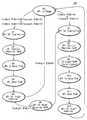
계속해서 도 5는 도 4에 도시된 유한 상태 머신의 하드웨어 자동 동작 제어 방식을 처리하기 위한 상태도이다.5 is a state diagram for processing the hardware automatic operation control scheme of the finite state machine shown in FIG.
도면을 참조하면, 상기 유한 상태 머신(130)은 대기 상태에서 전송 데이터의 전송 길이 데이터(TX Length)와 전송 속도 데이터(TX Rate)를 전송하기 위한 이벤트 신호들(ES_TXRate, ES_TXLength) 중 적어도 하나가 활성화되면, 해당 이벤트 신호에 응답해서 두 데이터를 연속해서 또는 둘 중 하나만 베이스밴드 프로세서(30)로 전송한다.Referring to the drawing, the
즉, 대기 상태(S0)에서 전송 속도 데이터(TX Rate)와 전송 데이터의 전송 길이 데이터(TX Length)를 모두 전송하거나 전송 속도 데이터(TX Rate) 만을 전송하기 위해서 상태 S1으로 상태 변환된다.That is, in the standby state SO, the state is converted to the state S1 in order to transmit both the transmission rate data TX rate and the transmission length data TX length of the transmission data or to transmit only the transmission rate data TX rate.
상태 S1에서 전송 속도 데이터(TX Rate)를 베이스밴드 프로세서(30)로 전송하기 위하여 SPI 칩선택 신호(SPICS)를 활성화시킨다. 상태 S2에서 제어 레지스터(104)의 값을 설정하고, 상태 S3으로 변환한다. 상태 S3에서는 전송할 데이터를 베이스밴드 프로세서(30)와 직렬 통신을 수행할 수 있도록 재구성한다.In the state S1, the SPI chip select signal SPICS is activated to transmit the transmission rate data TX rate to the
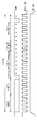
이 때, 전송 속도 데이터(TX Rate)는 도 6a에 도시된 바와 같이, 베이스밴드 프로세서(30)와의 직렬 통신 프로토콜에 따라 재구성된다. 전송 속도 데이터(TX Rate)는 MOSI를 통해 출력되며, MOSI 구성 값들 중에 칩 어드레스(chip address), 기입/독출(R/W), 자동 증가(Auto Increment : AI), 메모리 어드레스 포인터(Memory Address Pointer : MAP)들은 SPI에 의해 정해진 값으로 설정되지만, 유연성을 높이기 위하여 레지스터 프로그래밍 가능하도록 구성한다. 그리고 전송 속도 데이터(TX Rate)의 상위 4 비트는 무선 랜 펌웨어에 의해 입력된 값을 그대로 사용하며, 하위 4 비트는 데이터의 길이를 8 비트로 맞추기 위하여 임의의 값으로 구성하는 더미(Dummy) 비트들로 재구성하여 데이터 송수신에 아무런 영향을 주지 않도록 한다.At this time, the transmission rate data (TX Rate) is reconstructed according to the serial communication protocol with the
따라서 전송 속도 데이터(TX Rate)를 베이스밴드 프로세서(30)로 전송하기 위하여 상태 S1에서 상태 S5로 상태 변환된다. 다시 도 5를 참조하면, 상태 S4에서 SPI 데이터 전송이 완료되면 상태 S5로 상태 변환하여 SPI 칩선택 신호(SPICS)를 비활성화시킨다. 이어서 전송 데이터의 전송 길이 데이터(TX Length)의 전송 여부에 따라 상태 S0로 변환하여 대기 상태를 유지하거나 상태 S6으로 변환하여 전송 데이터의 전송 길이 데이터(TX Length)를 전송하기 위한 지속 시간을 유지한다.Therefore, the state transition from the state S1 to the state S5 in order to transmit the transmission rate data (TX Rate) to the
상태 S6는 전송 속도 데이터(TX Rate)와 전송 데이터의 전송 길이 데이터(TX Length)를 연속해서 전송하는 경우, 즉 SPI 회로(100)는 베이스밴드 프로세서(30)와 2 회의 직렬 통신이 수행될 때만 필요한 상태이다. 왜냐하면, 베이스밴드 프로세서(30)의 직렬 통신 프로토콜에 의하면 직렬 통신 사이에는 SPI 칩선택 신호(SPICS)가 일정 시간 동안 로직 하이 레벨을 유지해야 하기 때문이다. 따라서 도 4에 도시된 바와 같이, 타이머(106)를 하드웨어로 구비하여 프레임 간의 지속 시간(duration) 영역에 대응해서 SPI 칩선택 신호(SPICS)를 로직 하이 레벨로 유지되도록 일정 시간을 카운트한다.State S6 is a case where the transmission rate data (TX Rate) and the transmission length data (TX Length) of the transmission data are continuously transmitted, i.e., when the
그리고 상기 유한 상태 머신(130)은 상태 S0 또는 상태 S6에서 전송 데이터의 전송 길이 데이터(TX Length)를 전송하기 위하여 상태 S7로 상태 변환한다. 상태 S7에서 전송 데이터의 전송 길이 데이터(TX Length)를 전송할 수 있도록 SPI 칩선택 신호(SPICS)를 활성화시키고 상태 S8로 상태 변환한다. 상태 S8에서는 정해진 값대로 SPI 내부 제어 레지스터(104)를 설정한다. 이어서 상태 S9에서 전송 데이터의 전송 길이 데이터(TX Length)를 바이트(byte) 단위의 데이터에서 마이크로 세컨드(micro second) 단위의 데이터로 변환한다. 이는 무선 랜 펌웨어로부터 입력된 전송 데이터의 전송 길이 데이터(TX Length)는 바이트 단위이고, 베이스밴드 프로세서(30)로 전송하기 위한 데이터는 마이크로 세컨드 단위로 표현되어야 하기 때문이다. 따라서 유한 상태 머신(130)은 데이터 변환부(108)에서 전송 데이터의 전송 길이 데이터(TX Length)를 바이트 단위에서 마이크로 세컨드 단위로 변환하도록 한다.The
상태 S10에서 SPI 전송 데이터를 베이스밴드 프로세서(30)가 직렬 통신 프로토콜에 의해 인식되도록 재구성한다. 재구성된 전송 데이터의 전송 길이 데이터(TX Length)는 도 6b에 도시된 바와 같이, 데이터 구성 값들 중 칩 어드레스, 기입/독출, 자동 증가, 메모리 어드레스 포인터 값들은 이미 정해진 값들로 레지스터 프로그래머블 가능하도록 하고, 전송 길이 데이터(TX Length)는 무선 랜 펌웨어로부터 입력된 바이트 단위의 전송 데이터의 전송 길이 데이터 값을 마이크로 세컨드 단위로 변환된 데이터(DATA1 ~ DATA3)를 이용하여 재구성한다.In state S10, the SPI transmission data is reconfigured so that the
그리고 상태 S11에서 재구성된 SPI 데이터를 전송한다. 이어서 상태 S12에서 SPI 칩선택 신호(SPICS)를 비활성하고, 상태 S0로 변환하여 대기 상태를 유지한다.In step S11, the reconstructed SPI data is transmitted. In the state S12, the SPI chip select signal SPICS is inactivated, and the state is switched to state S0 to maintain the standby state.
따라서 유한 상태 머신(130)을 이용하여 정해진 동작 수순에 의해 미디어 억세스 컨트롤러(20)와 베이스밴드 프로세서(30) 간에 직렬 데이터 통신이 수행된다.Accordingly, serial data communication is performed between the
상술한 바와 같이, 직렬 데이터 통신 인터페이스를 이용한 데이터 전송시, 마스터인 MAC 컨트롤러가 수신 프레임의 헤더를 보고 SIFS 이전에 전송 속도 데이터를 슬레이브인 베이스밴드 프로세서로 전송한다. 따라서, SIFS 구간 내에 전송 길이 정보를 베이스밴드 프로세서로 전송하고, 베이스밴드 프로세서가 워밍업될 수 있다.As described above, during data transmission using the serial data communication interface, the MAC controller as the master sees the header of the received frame and transmits the transmission rate data to the slave baseband processor before SIFS. Therefore, transmission length information is transmitted to the baseband processor within the SIFS interval, and the baseband processor may be warmed up.
또한 상술한 바와 같이, 직렬 데이터 전송 장치를 소프트웨어 제어 방식 및 하드웨어 자동 제어 방식의 하이브리드 형으로 구비하여, 하드웨어 자동 제어 방식에 의해 데이터 전송 장치의 정확한 동작 시간이 예측 가능하게 되고, 전송 속도 데이터와 전송 길이 데이터 전송시, 미리 전송 속도 데이터를 전송함으로써, 짧은 인터프레임 시간 동안에 임계 시점을 정확히 조절할 수 있다. 즉, 전송 속도 데이터의 전송 시기를 앞당겨서 ACK 프레임 이전에 전송 속도 데이터 및 전송 길이 데이터를 슬레이브로 전송하고, 슬레이브의 워밍업까지 완전하게 수행함으로써 고속의 전송 시스템의 안정된 동작을 보장할 수 있다. 그 결과 무선 랜 환경에서의 직렬 주변장치 인터페이스를 이용하여 고속의 직렬 통신을 이룰 수 있다.In addition, as described above, the serial data transmission device is provided in a hybrid type of software control method and hardware automatic control method, and the accurate operation time of the data transmission device can be predicted by the hardware automatic control method, and the transmission speed data and the transmission can be predicted. In transmitting the length data, by transmitting the transmission rate data in advance, it is possible to accurately adjust the threshold time point for a short interframe time. That is, it is possible to ensure stable operation of the high-speed transmission system by advancing the transmission time of the transmission rate data, transmitting the transmission rate data and the transmission length data to the slave before the ACK frame, and performing the warming up of the slave completely. As a result, high-speed serial communication can be achieved using a serial peripheral interface in a wireless LAN environment.
Claims (22)
Translated fromKoreanPriority Applications (5)
| Application Number | Priority Date | Filing Date | Title |
|---|---|---|---|
| KR20030012069AKR100614638B1 (en) | 2003-02-26 | 2003-02-26 | Hybrid Serial Peripheral Interface Interface Suitable for High-Speed Wireless Communication and Its Method |
| TW93104539ATWI257787B (en) | 2003-02-26 | 2004-02-24 | Hybrid-type data transmission apparatus and method suitable for high-performance wireless LAN |
| CN200410038775ACN100592730C (en) | 2003-02-26 | 2004-02-26 | Hybrid data transmission device and method suitable for high-performance wireless local area network |
| JP2004051256AJP4318566B2 (en) | 2003-02-26 | 2004-02-26 | Hybrid data transmission apparatus and method suitable for high-speed wireless communication |
| US10/787,671US7453833B2 (en) | 2003-02-26 | 2004-02-26 | Hybrid-type data transmission apparatus and method suitable for high-performance wireless LAN |
Applications Claiming Priority (1)
| Application Number | Priority Date | Filing Date | Title |
|---|---|---|---|
| KR20030012069AKR100614638B1 (en) | 2003-02-26 | 2003-02-26 | Hybrid Serial Peripheral Interface Interface Suitable for High-Speed Wireless Communication and Its Method |
Publications (2)
| Publication Number | Publication Date |
|---|---|
| KR20040076730A KR20040076730A (en) | 2004-09-03 |
| KR100614638B1true KR100614638B1 (en) | 2006-08-23 |
Family
ID=32923749
Family Applications (1)
| Application Number | Title | Priority Date | Filing Date |
|---|---|---|---|
| KR20030012069AExpired - Fee RelatedKR100614638B1 (en) | 2003-02-26 | 2003-02-26 | Hybrid Serial Peripheral Interface Interface Suitable for High-Speed Wireless Communication and Its Method |
Country Status (5)
| Country | Link |
|---|---|
| US (1) | US7453833B2 (en) |
| JP (1) | JP4318566B2 (en) |
| KR (1) | KR100614638B1 (en) |
| CN (1) | CN100592730C (en) |
| TW (1) | TWI257787B (en) |
Families Citing this family (19)
| Publication number | Priority date | Publication date | Assignee | Title |
|---|---|---|---|---|
| US7561558B2 (en)* | 2002-09-10 | 2009-07-14 | Koninklijke Philips Electronics N.V. | Transmission power optimization of OFDM wireless communication system |
| US8234399B2 (en)* | 2003-05-29 | 2012-07-31 | Seagate Technology Llc | Method and apparatus for automatic phy calibration based on negotiated link speed |
| US20050215248A1 (en)* | 2004-03-23 | 2005-09-29 | Texas Instruments Incorporated | Method and system of communication between a master device and a slave device |
| WO2006016745A1 (en)* | 2004-08-12 | 2006-02-16 | Samsung Electronics Co., Ltd. | Method and apparatus for transmitting ack frame |
| TWI287375B (en)* | 2004-11-23 | 2007-09-21 | Inst Information Industry | Parallel transmission method and the system of a wireless local area network |
| US7917173B2 (en)* | 2006-06-13 | 2011-03-29 | Pixart Imaging Inc. | Multimedia data communication method and system |
| US20090138638A1 (en) | 2007-11-27 | 2009-05-28 | Microsoft Corporation | Serial Peripheral Interface for a Transceiver Integrated Circuit |
| EP2490339A4 (en)* | 2009-10-14 | 2015-01-14 | Nec Corp | Wireless communication device and method for controlling the state between rfic and bbic thereof |
| US8510487B2 (en)* | 2010-02-11 | 2013-08-13 | Silicon Image, Inc. | Hybrid interface for serial and parallel communication |
| KR20120055034A (en)* | 2010-11-22 | 2012-05-31 | 삼성전자주식회사 | Apparatus for connecting peripheral device in portable terminal using serial peripheral interface and method for transmitting data |
| US9071243B2 (en) | 2011-06-30 | 2015-06-30 | Silicon Image, Inc. | Single ended configurable multi-mode driver |
| US8760188B2 (en) | 2011-06-30 | 2014-06-24 | Silicon Image, Inc. | Configurable multi-dimensional driver and receiver |
| CN102508799B (en)* | 2011-11-30 | 2014-12-24 | 北京宏思电子技术有限责任公司 | Automatic control method, system and USB (universal serial bus) device |
| CN104253900B (en)* | 2013-06-28 | 2017-03-15 | 展讯通信(上海)有限公司 | Smart mobile phone and its data transmission method and system |
| CN103744814B (en)* | 2014-01-06 | 2017-01-11 | 深圳市芯海科技有限公司 | High speed communication method by two lines |
| CN104597817A (en)* | 2015-01-12 | 2015-05-06 | 北京慧物科联科技有限公司 | Parallel acquisition system of multi-channel digital sensor |
| US9829913B2 (en)* | 2015-06-02 | 2017-11-28 | Goodrich Corporation | System and method of realignment of read data by SPI controller |
| KR101925912B1 (en)* | 2016-12-19 | 2018-12-06 | 주식회사 엘지유플러스 | Packet Processing Method and Apparatus |
| US11301414B1 (en)* | 2019-12-19 | 2022-04-12 | Cadence Design Systems, Inc. | Systems and methods for communicating with clients with non-deterministic response delay over a communication interface |
Family Cites Families (5)
| Publication number | Priority date | Publication date | Assignee | Title |
|---|---|---|---|---|
| US4509164A (en)* | 1981-11-30 | 1985-04-02 | Queen's University At Kingston | Microprocessor based digital to digital converting dataset |
| US6334219B1 (en)* | 1994-09-26 | 2001-12-25 | Adc Telecommunications Inc. | Channel selection for a hybrid fiber coax network |
| KR100230375B1 (en) | 1996-10-10 | 1999-11-15 | 윤종용 | Serial data communication system |
| US7561558B2 (en)* | 2002-09-10 | 2009-07-14 | Koninklijke Philips Electronics N.V. | Transmission power optimization of OFDM wireless communication system |
| US7263105B2 (en)* | 2002-12-18 | 2007-08-28 | Intel Corporation | WLAN device and method for interfacing between a MAC sublayer and a physical layer |
- 2003
- 2003-02-26KRKR20030012069Apatent/KR100614638B1/ennot_activeExpired - Fee Related
- 2004
- 2004-02-24TWTW93104539Apatent/TWI257787B/ennot_activeIP Right Cessation
- 2004-02-26JPJP2004051256Apatent/JP4318566B2/ennot_activeExpired - Fee Related
- 2004-02-26USUS10/787,671patent/US7453833B2/enactiveActive
- 2004-02-26CNCN200410038775Apatent/CN100592730C/ennot_activeExpired - Lifetime
Also Published As
| Publication number | Publication date |
|---|---|
| JP4318566B2 (en) | 2009-08-26 |
| TWI257787B (en) | 2006-07-01 |
| TW200420034A (en) | 2004-10-01 |
| KR20040076730A (en) | 2004-09-03 |
| US7453833B2 (en) | 2008-11-18 |
| CN1538703A (en) | 2004-10-20 |
| US20040174831A1 (en) | 2004-09-09 |
| CN100592730C (en) | 2010-02-24 |
| JP2004260831A (en) | 2004-09-16 |
Similar Documents
| Publication | Publication Date | Title |
|---|---|---|
| KR100614638B1 (en) | Hybrid Serial Peripheral Interface Interface Suitable for High-Speed Wireless Communication and Its Method | |
| US8694710B2 (en) | Conversion of a two-wire bus into a single-wire bus | |
| US6625472B1 (en) | Apparatus and method for connecting a cellular telephone to a universal serial bus | |
| RU2352980C2 (en) | Compatibility of single-wire and three-wire buses | |
| US20150220472A1 (en) | Increasing throughput on multi-wire and multi-lane interfaces | |
| JP2002232508A (en) | Electronic device and method for automatically selecting interface protocol used by the electronic device | |
| US12306787B2 (en) | Communication device, communication system, and communication method | |
| EP2540135A1 (en) | Scalable digrf architecture | |
| US7231467B2 (en) | Method and apparatus for providing an inter integrated circuit interface with an expanded address range and efficient priority-based data throughput | |
| US7421527B2 (en) | Transmission apparatus and transmission method | |
| CA2808595A1 (en) | A packet structure for a mobile display digital interface | |
| CN117640783B (en) | Data transmission method, system, electronic equipment and readable medium | |
| JP2007074641A (en) | Communication system | |
| JP2004334551A (en) | Serial communication system and local terminal for serial communication | |
| JP5661702B2 (en) | Electronic system and communication control method | |
| KR100361511B1 (en) | Multi-Function Serial Communication Interface Device | |
| JP2006079621A (en) | Digital programming interface between baseband processor and radio frequency integrated module | |
| WO2004012405A9 (en) | Packet processing architecture | |
| JP2006304011A (en) | Interface circuit | |
| KR100295683B1 (en) | General call acknowledge apparatus and method for inter-integrated circuit | |
| KR100427764B1 (en) | Apparatus for Interface between Devices of different Data Bus | |
| CN120045481A (en) | Electronic device and data transmission control method | |
| CN118069556A (en) | Method for realizing UART communication by software simulation | |
| CN117785773A (en) | Serial communication interface protocol | |
| KR100962306B1 (en) | Bidirectional Data Communication Device of Embedded System and Its Method |
Legal Events
| Date | Code | Title | Description |
|---|---|---|---|
| A201 | Request for examination | ||
| PA0109 | Patent application | St.27 status event code:A-0-1-A10-A12-nap-PA0109 | |
| PA0201 | Request for examination | St.27 status event code:A-1-2-D10-D11-exm-PA0201 | |
| P11-X000 | Amendment of application requested | St.27 status event code:A-2-2-P10-P11-nap-X000 | |
| P13-X000 | Application amended | St.27 status event code:A-2-2-P10-P13-nap-X000 | |
| R15-X000 | Change to inventor requested | St.27 status event code:A-3-3-R10-R15-oth-X000 | |
| R16-X000 | Change to inventor recorded | St.27 status event code:A-3-3-R10-R16-oth-X000 | |
| R18-X000 | Changes to party contact information recorded | St.27 status event code:A-3-3-R10-R18-oth-X000 | |
| PG1501 | Laying open of application | St.27 status event code:A-1-1-Q10-Q12-nap-PG1501 | |
| D13-X000 | Search requested | St.27 status event code:A-1-2-D10-D13-srh-X000 | |
| D14-X000 | Search report completed | St.27 status event code:A-1-2-D10-D14-srh-X000 | |
| E902 | Notification of reason for refusal | ||
| PE0902 | Notice of grounds for rejection | St.27 status event code:A-1-2-D10-D21-exm-PE0902 | |
| T11-X000 | Administrative time limit extension requested | St.27 status event code:U-3-3-T10-T11-oth-X000 | |
| E13-X000 | Pre-grant limitation requested | St.27 status event code:A-2-3-E10-E13-lim-X000 | |
| P11-X000 | Amendment of application requested | St.27 status event code:A-2-2-P10-P11-nap-X000 | |
| P13-X000 | Application amended | St.27 status event code:A-2-2-P10-P13-nap-X000 | |
| PN2301 | Change of applicant | St.27 status event code:A-3-3-R10-R13-asn-PN2301 St.27 status event code:A-3-3-R10-R11-asn-PN2301 | |
| PN2301 | Change of applicant | St.27 status event code:A-3-3-R10-R13-asn-PN2301 St.27 status event code:A-3-3-R10-R11-asn-PN2301 | |
| E902 | Notification of reason for refusal | ||
| PE0902 | Notice of grounds for rejection | St.27 status event code:A-1-2-D10-D21-exm-PE0902 | |
| P11-X000 | Amendment of application requested | St.27 status event code:A-2-2-P10-P11-nap-X000 | |
| P13-X000 | Application amended | St.27 status event code:A-2-2-P10-P13-nap-X000 | |
| E701 | Decision to grant or registration of patent right | ||
| PE0701 | Decision of registration | St.27 status event code:A-1-2-D10-D22-exm-PE0701 | |
| GRNT | Written decision to grant | ||
| PR0701 | Registration of establishment | St.27 status event code:A-2-4-F10-F11-exm-PR0701 | |
| PR1002 | Payment of registration fee | St.27 status event code:A-2-2-U10-U11-oth-PR1002 Fee payment year number:1 | |
| PG1601 | Publication of registration | St.27 status event code:A-4-4-Q10-Q13-nap-PG1601 | |
| PR1001 | Payment of annual fee | St.27 status event code:A-4-4-U10-U11-oth-PR1001 Fee payment year number:4 | |
| PR1001 | Payment of annual fee | St.27 status event code:A-4-4-U10-U11-oth-PR1001 Fee payment year number:5 | |
| PR1001 | Payment of annual fee | St.27 status event code:A-4-4-U10-U11-oth-PR1001 Fee payment year number:6 | |
| R18-X000 | Changes to party contact information recorded | St.27 status event code:A-5-5-R10-R18-oth-X000 | |
| FPAY | Annual fee payment | Payment date:20120801 Year of fee payment:7 | |
| PR1001 | Payment of annual fee | St.27 status event code:A-4-4-U10-U11-oth-PR1001 Fee payment year number:7 | |
| FPAY | Annual fee payment | Payment date:20130731 Year of fee payment:8 | |
| PR1001 | Payment of annual fee | St.27 status event code:A-4-4-U10-U11-oth-PR1001 Fee payment year number:8 | |
| FPAY | Annual fee payment | Payment date:20140731 Year of fee payment:9 | |
| PR1001 | Payment of annual fee | St.27 status event code:A-4-4-U10-U11-oth-PR1001 Fee payment year number:9 | |
| PR1001 | Payment of annual fee | St.27 status event code:A-4-4-U10-U11-oth-PR1001 Fee payment year number:10 | |
| FPAY | Annual fee payment | Payment date:20160801 Year of fee payment:11 | |
| PR1001 | Payment of annual fee | St.27 status event code:A-4-4-U10-U11-oth-PR1001 Fee payment year number:11 | |
| PR1001 | Payment of annual fee | St.27 status event code:A-4-4-U10-U11-oth-PR1001 Fee payment year number:12 | |
| FPAY | Annual fee payment | Payment date:20180731 Year of fee payment:13 | |
| PR1001 | Payment of annual fee | St.27 status event code:A-4-4-U10-U11-oth-PR1001 Fee payment year number:13 | |
| FPAY | Annual fee payment | Payment date:20190731 Year of fee payment:14 | |
| PR1001 | Payment of annual fee | St.27 status event code:A-4-4-U10-U11-oth-PR1001 Fee payment year number:14 | |
| PR1001 | Payment of annual fee | St.27 status event code:A-4-4-U10-U11-oth-PR1001 Fee payment year number:15 | |
| PR1001 | Payment of annual fee | St.27 status event code:A-4-4-U10-U11-oth-PR1001 Fee payment year number:16 | |
| PC1903 | Unpaid annual fee | St.27 status event code:A-4-4-U10-U13-oth-PC1903 Not in force date:20220815 Payment event data comment text:Termination Category : DEFAULT_OF_REGISTRATION_FEE | |
| PC1903 | Unpaid annual fee | St.27 status event code:N-4-6-H10-H13-oth-PC1903 Ip right cessation event data comment text:Termination Category : DEFAULT_OF_REGISTRATION_FEE Not in force date:20220815 |