KR100610191B1 - Motorized Buckle Pretensioner - Google Patents
Motorized Buckle PretensionerDownload PDFInfo
- Publication number
- KR100610191B1 KR100610191B1KR1020040055914AKR20040055914AKR100610191B1KR 100610191 B1KR100610191 B1KR 100610191B1KR 1020040055914 AKR1020040055914 AKR 1020040055914AKR 20040055914 AKR20040055914 AKR 20040055914AKR 100610191 B1KR100610191 B1KR 100610191B1
- Authority
- KR
- South Korea
- Prior art keywords
- gear
- cable
- pretensioner
- motor
- buckle
- Prior art date
- Legal status (The legal status is an assumption and is not a legal conclusion. Google has not performed a legal analysis and makes no representation as to the accuracy of the status listed.)
- Expired - Fee Related
Links
Images


Classifications
- B—PERFORMING OPERATIONS; TRANSPORTING
- B60—VEHICLES IN GENERAL
- B60R—VEHICLES, VEHICLE FITTINGS, OR VEHICLE PARTS, NOT OTHERWISE PROVIDED FOR
- B60R22/00—Safety belts or body harnesses in vehicles
- B60R22/34—Belt retractors, e.g. reels
- B60R22/46—Reels with means to tension the belt in an emergency by forced winding up
- B60R22/4604—Reels with means to tension the belt in an emergency by forced winding up characterised by arrangements in vehicle or relative to seat belt
- B—PERFORMING OPERATIONS; TRANSPORTING
- B60—VEHICLES IN GENERAL
- B60R—VEHICLES, VEHICLE FITTINGS, OR VEHICLE PARTS, NOT OTHERWISE PROVIDED FOR
- B60R22/00—Safety belts or body harnesses in vehicles
- B60R22/18—Anchoring devices
- B60R22/195—Anchoring devices with means to tension the belt in an emergency, e.g. means of the through-anchor or splitted reel type
- B60R22/1951—Anchoring devices with means to tension the belt in an emergency, e.g. means of the through-anchor or splitted reel type characterised by arrangements in vehicle or relative to seat belt
- B—PERFORMING OPERATIONS; TRANSPORTING
- B60—VEHICLES IN GENERAL
- B60R—VEHICLES, VEHICLE FITTINGS, OR VEHICLE PARTS, NOT OTHERWISE PROVIDED FOR
- B60R22/00—Safety belts or body harnesses in vehicles
- B60R22/34—Belt retractors, e.g. reels
- B60R22/46—Reels with means to tension the belt in an emergency by forced winding up
- B60R22/4676—Reels with means to tension the belt in an emergency by forced winding up comprising energy-absorbing means operating between belt reel and retractor frame
- B—PERFORMING OPERATIONS; TRANSPORTING
- B60—VEHICLES IN GENERAL
- B60R—VEHICLES, VEHICLE FITTINGS, OR VEHICLE PARTS, NOT OTHERWISE PROVIDED FOR
- B60R11/00—Arrangements for holding or mounting articles, not otherwise provided for
- B60R2011/0001—Arrangements for holding or mounting articles, not otherwise provided for characterised by position
- B60R2011/0003—Arrangements for holding or mounting articles, not otherwise provided for characterised by position inside the vehicle
- B60R2011/0031—Seat belts
- B—PERFORMING OPERATIONS; TRANSPORTING
- B60—VEHICLES IN GENERAL
- B60R—VEHICLES, VEHICLE FITTINGS, OR VEHICLE PARTS, NOT OTHERWISE PROVIDED FOR
- B60R21/00—Arrangements or fittings on vehicles for protecting or preventing injuries to occupants or pedestrians in case of accidents or other traffic risks
- B60R21/01—Electrical circuits for triggering passive safety arrangements, e.g. airbags, safety belt tighteners, in case of vehicle accidents or impending vehicle accidents
- B60R2021/01204—Actuation parameters of safety arrangents
- B60R2021/01252—Devices other than bags
- B60R2021/01265—Seat belts
- B60R2021/01272—Belt tensioners
- B—PERFORMING OPERATIONS; TRANSPORTING
- B60—VEHICLES IN GENERAL
- B60R—VEHICLES, VEHICLE FITTINGS, OR VEHICLE PARTS, NOT OTHERWISE PROVIDED FOR
- B60R22/00—Safety belts or body harnesses in vehicles
- B60R22/34—Belt retractors, e.g. reels
- B60R22/46—Reels with means to tension the belt in an emergency by forced winding up
- B60R2022/469—Reels with means to tension the belt in an emergency by forced winding up reusable
Landscapes
- Engineering & Computer Science (AREA)
- Mechanical Engineering (AREA)
- Automotive Seat Belt Assembly (AREA)
Abstract
Translated fromKoreanDescription
Translated fromKorean도 1은 종래의 버클 프리텐셔너가 장착된 시트를 도시하는 사시도,1 is a perspective view showing a seat on which a conventional buckle pretensioner is mounted;
도 2는 종래의 버클 프리텐셔너를 도시하는 일부절개도,2 is a partial cutaway view showing a conventional buckle pretensioner,
도 3은 본 발명의 모터구동형 버클 프리텐셔너의 일 실시예를 도시하는Figure 3 illustrates one embodiment of a motor-driven buckle pretensioner of the present invention.
일부절개도,Incision,
도 4a는 본 발명의 모터구동형 버클 프리텐셔너의 제1작동도,Figure 4a is a first operation of the motor-driven buckle pretensioner of the present invention,
도 4b는 본 발명의 모터구동형 버클 프리텐셔너의 제2작동도,Figure 4b is a second operation of the motor-driven buckle pretensioner of the present invention,
도 4c는 본 발명의 모터구동형 버클 프리텐셔너의 제3작동도,Figure 4c is a third operation of the motor-driven buckle pretensioner of the present invention,
도 4d는 본 발명의 모터구동형 버클 프리텐셔너의 제4작동도,Figure 4d is a fourth operation of the motor-driven buckle pretensioner of the present invention,
도 4e는 본 발명의 모터구동형 버클 프리텐셔너의 제5작동도.Figure 4e is a fifth operation of the motor-driven buckle pretensioner of the present invention.
<도면의 주요 부분에 대한 부호의 설명><Explanation of symbols for the main parts of the drawings>
10 : 케이블11 : 버클10 cable 11: buckle
12 : 프리텐셔너 케이스20 : 구동모터12: pretensioner case 20: drive motor
30 : 기어부31 : 랙기어30: gear part 31: rack gear
32 : 피니언기어33 : 래치기어32: pinion gear 33: latch gear
34 : 회전량측정기35: 구름수단34: rotation amount measuring instrument 35: rolling means
40 : 잠금부41 : 래치잠금키40: lock portion 41: latch lock key
42 : 전자석50 : 충돌감지센서42: electromagnet 50: collision detection sensor
60 : 가속도센서70 : 승객감지센서60: acceleration sensor 70: passenger detection sensor
80 : 제어부80: control unit
본 발명은 모터구동형 버클 프리텐셔너에 관한 것으로서, 특히 전동식으로 동작되어 반복적으로 사용할 수 있는 모터구동형 버클 프리텐셔너에 관한 것이다.The present invention relates to a motor-driven buckle pretensioner, and more particularly to a motor-driven buckle pretensioner that can be operated electrically and repeatedly used.
충돌사고가 발생시에 시트벨트의 구속효과를 높이기 위하여 각종 프리텐셔너를 사용하는데 그 중에서 버클에 장착된 버클 프리텐셔너는 적은 이동량으로도 큰 구속효과를 볼 수 있으므로 리트랙터 프리텐셔너와 함께 널리 사용되고 있다.Various pretensioners are used to increase the restraint effect of the seat belt when a crash occurs. Among them, the buckle pretensioner mounted on the buckle has a large restraint effect even with a small amount of movement, so it is widely used with the retractor pretensioner.
종래의 버클 프리텐셔너는 화약이 발화되면서 발생하는 팽창가스가 피스톤을 밀어내면서 버클에 연결된 케이블을 잡아당기는 작동을 함으로써 시트벨트의 구속력을 강화시키며, 충돌시에 탑승자의 몸이 앞으로 쏠리는 힘에 의하여 그 이동이 로킹되어 고정되는 구조이다.Conventional buckle pretensioner strengthens the seat belt's binding force by acting to pull the cable connected to the buckle while the expansion gas generated by the ignition of the powder pushes the piston, and moves by the force of the occupant's body in the event of a collision. This structure is locked and fixed.
도 1은 종래의 버클 프리텐셔너가 장착된 시트를 도시하는 사시도로서, 버클(1)의 하측으로 연결되어, 시트벨트의 구속력을 강화하기 위하여 장착된 버클 프리텐셔너(2)를 도시하고 있다.Fig. 1 is a perspective view showing a seat on which a conventional buckle pretensioner is mounted, which is connected to the lower side of the
도 2는 종래의 버클 프리텐셔너를 도시하는 일부절개도로서, 충돌감지센서(3)로부터 충돌신호를 수신한 제어부(4)가 버클 프리텐셔너(2)의 내부에 설치된 인플레이터(5)를 동작하여 화약을 발화하면, 팽창된 가스로 인하여 케이블(6)에 부착된 피스톤(7)이 뒤로 후퇴되고 상기 케이블(6)이 일체로 뒤로 당겨지면서 가속되어 버클의 구속력을 강화하는 것을 나타내며, 가속후에는 탑승자의 무게를 지탱할 수 있도록 로킹이 되어야 하는데, 충돌시 상기 케이블(6)에 탑승자의 무게가 실리면서 상기 케이블(6)이 역방향으로 이동되고 상기 케이블(6)에 부착된 잠금장치(8)도 일체로 이동되면서 상기 실린더(9) 내벽의 변형을 일으키며 변형된 부위와의 마찰로 인하여 로킹되는 것을 나타낸다.FIG. 2 is a partial cutaway view of a conventional buckle pretensioner, in which a
그런데, 상기한 바와 같은, 종래의 버클 프리텐셔너는, 충돌시 한번밖에 사용할 수 없으며, 화약을 발화시키는 인플레이터가 고가이며, 제품에 따라 실린더 내벽이 변형되는 형상과 시점이 다름으로 인하여 로킹되는 위치가 일정하지 않다는 문제점이 있었다.However, as described above, the conventional buckle pretensioner can be used only once in a collision, and the inflator for igniting the explosives is expensive, and the locked position is fixed due to the different shape and viewpoint of the cylinder inner wall being deformed depending on the product. There was a problem that not.
본 발명은 상기의 결점을 해소하기 위한 것으로 전동식으로 동작되어 반복적으로 사용할 수 있으므로 원가를 절감할 수 있으며, 충돌시뿐만 아니라 급제동시에도 사용할 수 있는 모터구동형 버클 프리텐셔너를 제공하고자 한다.
The present invention is to solve the above-mentioned drawbacks can be used repeatedly because it is electrically operated to reduce the cost, and to provide a motor-driven buckle pretensioner that can be used in case of sudden braking as well as in the event of a crash.
이러한 본 발명은, 일단이 버클에 연결 고정되며 타단이 프리텐셔너 케이스 내부로 연결되는 케이블과; 상기 케이블의 타단을 고정하며, 상기 프리텐셔너 케이스의 내부에 설치되는 구동모터에 의하여 동작되어, 상기 케이블을 이동시키는 기어부와; 상기 기어부의 회동을 구속하는 잠금부와; 충돌감지센서로부터 신호를 수신하여 상기 구동모터와 상기 잠금부를 제어하는 제어부를 구성함으로써 달성된다.
The present invention, the one end is connected to the buckle and the other end is connected to the cable inside the pretensioner case; A gear part fixed to the other end of the cable and operated by a driving motor installed inside the pretensioner case to move the cable; A locking portion for restraining rotation of the gear portion; Receiving a signal from a collision detection sensor is achieved by configuring a control unit for controlling the drive motor and the lock.
본 발명의 실시예를 첨부 도면을 참고하여 상세히 설명하면 다음과 같다.An embodiment of the present invention will be described in detail with reference to the accompanying drawings.
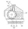
도 3은 본 발명의 모터구동형 버클 프리텐셔너의 일 실시예를 도시하는 일부절개도로서, 일단이 버클(11)에 연결 고정되며 타단이 프리텐셔너 케이스(12) 내부로 연결되는 케이블(10)과; 상기 케이블(10)의 타단을 고정하며, 상기 프리텐셔너 케이스(12)의 내부에 설치되는 구동모터(20)에 의하여 동작되어, 상기 케이블(10)을 이동시키는 기어부(30)와; 상기 기어부(30)의 회동을 구속하는 잠금부(40)와; 충돌감지센서(50)로부터 신호를 수신하여 상기 구동모터(20)와 상기 잠금부(40)를 제어하는 제어부(80)로 구성되며, 상기 기어부(30)는 상기 케이블(10)의 타단에 부착되어 설치되는 랙기어(31)와; 상기 랙기어(31)에 치합되며, 상기 구동모터(22)에 연결되는 피니언기어(32)와; 상기 피니언기어(32)의 축에 고정되어 설치되어, 상기 피니언기어(32)와 일체로 회동되는 래치기어(33)로 구성되며, 또한 상기 잠금부(40)는 상기 기어부(30)의 상기 래치기어(33)의 상측에 설치되어 상기 래치기어(33)의 회동을 구속함으로써 상기 기어부(30)의 회동을 구속하는 래치잠금키(41)와; 상기 제어부(80)의 제어신호에 의하여 상기 래치잠금키(41)를 이동시키는 전자석(42)으로 구성된다.3 is a partial cutaway view showing an embodiment of the motor-driven buckle pretensioner of the present invention, one end of which is connected to the
도 4a는 본 발명의 모터구동형 버클 프리텐셔너의 제1작동도로서, 전자석(42)에 공급되는 전원이 차단된 상태에서 래치잠금키(41)는 임의의 위치에 놓여있고, 구동모터(20)가 시계방향으로 회전하면 상기 구동모터(20)에 연결되는 피니언기어(32)가 반시계방향으로 회전되고 상기 피니언기어(32)와 치합되는 랙기어(31)가 우측으로 이동되어, 상기 랙기어(31)에 연결되는 케이블(10:도 3참조)이 당겨지는 것을 나타낸다.4A is a first operation diagram of the motor-driven buckle pretensioner of the present invention, in which the
이때, 상기 피니언기어(32)의 상측에 설치되는 회전량측정기(34)는 상기 피니언기어(32)의 반시계방향의 회전량을 계측하여 제어부(80:도 3참조)에 전송하게 된다.At this time, the rotation
도 4b는 본 발명의 모터구동형 버클 프리텐셔너의 제2작동도로서, 구동모터(20)의 작동이 중단된 상태에서, 충돌이나 급제동으로 인하여 승객의 하중이 케이블(10:도 3참조)에 실리게 되는데, 이때 승객의 실리는 하중에 의하여 상기 케이블(10:도 3참조)이 좌측으로 당겨지고, 상기 케이블(10:도 3참조)과 일체로 랙기어(31)가 좌측으로 이동됨에 따라 상기 랙기어(31)에 치합되는 피니언기어(32)가 시계방향으로 회전되는데, 이때 래치잠금키(41)가 하측으로 이동되어 래치기어(33)에 걸림으로써 승객의 하중을 지탱하는 것을 나타낸다.4B is a second operation diagram of the motor-driven buckle pretensioner of the present invention, in which the load of the passenger is carried on the cable 10 (see FIG. 3) due to collision or sudden braking while the
이때, 상기 피니언기어(32)의 상측에 설치되는 회전량측정기(34)는 상기 피니언기어(32)의 시계방향의 회전량을 계측하여 제어부(80:도 3참조)에 전송하게 된다.At this time, the rotation
도 4c는 본 발명의 모터구동형 버클 프리텐셔너의 제3작동도로서, 충돌 및 급제동이 종료한 후에 전자석(42)에 전원이 공급되고, 래치잠금키(41)가 상승하도록 구동모터(20)가 시계방향으로 정회전하는 것을 나타낸다.4C is a third operation diagram of the motor-driven buckle pretensioner of the present invention, in which power is supplied to the electromagnet 42 after the collision and sudden braking is completed, and the driving
이때, 피니언기어(32)의 상측에 설치되는 회전량측정기(34)는 상기 피니언기어(32)의 반시계방향의 회전량을 계측하여 제어부(80:도3참조)에 전송하게 된다.At this time, the rotation
도 4d는 본 발명의 모터구동형 버클 프리텐셔너의 제4작동도로서, 구동모터(20)가 반시계방향으로 회전하여 상기 구동모터(20)에 연결되는 피니언기어(33)를 시계방향으로 회전시킴으로써, 상기 피니언기어(33)에 치합되는 랙기어(31)가 좌측으로 이동되고 상기 랙기어(31)에 연결되는 케이블(10:도 3참조)이 최초의 위치로 복귀되는 것을 나타낸다.4D is a fourth operation diagram of the motor-driven buckle pretensioner of the present invention, in which the
이때, 상기 피니언기어(32)의 상측에 설치되는 회전량측정기(34)는 상기 피니언기어(32)의 시계방향의 회전량을 계측하여 제어부(80:도3참조)에 전송하게 된다.At this time, the rotation
도 4e는 본 발명의 모터구동형 버클 프리텐셔너의 제5작동도로서, 전자석(42)에 전원 공급이 차단되며, 버클 프리텐셔너가 초기화되는 상태를 나타낸 다.Figure 4e is a fifth operation of the motor-driven buckle pretensioner of the present invention, the power supply to the electromagnet 42 is cut off, and shows a state in which the buckle pretensioner is initialized.
한편, 가속도센서(60)가 추가 구성되어, 상기 제어부(80)가 상기 가속도센서(60)로부터 신호를 수신하여 상기 구동모터(20)와 상기 잠금부(40)를 제어하는 것이 바람직한 실시예이다.On the other hand, the
상기 가속도센서(60)로 인하여 충돌시뿐만 아니라 급제동시에도 상기 구동모터(20)와 상기 잠금부(40)의 작동이 가능한 것이다.Due to the
또한, 승객감지센서(70)가 추가로 구성되어, 상기 제어부(80)가 상기 승객감지센서(70)로부터 수신하여 상기 구동모터(20)와 상기 잠금부(40)를 제어하는 것이 바람직한 실시예이다.In addition, the
한편, 상기 승객감지센서(70)에서 감지된 승객의 체형에 따라 상기 구동모터(20)를 동작하여 상기 케이블(10)의 이동거리를 조절할 수 있도록 하는 것이 그 바람직한 실시예이다.On the other hand, it is a preferred embodiment to be able to adjust the moving distance of the
또한, 상기 피니언기어(32)의 상측에 회전량측정기(34)가 설치되어 상기 피니언기어(32)의 회전량을 검출하여 상기 제어부(80)에 전송하는 것이 바람직하다.In addition, the rotation
그리고, 상기 랙기어(31)의 저면으로 구름수단(35)이 설치되어 상기 랙기어(31)의 이동을 원활하게 하는 것이 그 바람직한 실시예이다.In addition, the
이하, 상기 도 3 또는 도 4를 참고하여 본 발명의 작용 및 효과를 설명하면 아래와 같다.Hereinafter, the operation and effects of the present invention will be described with reference to FIG. 3 or FIG. 4.
충돌감지센서(50)로부터 충돌을 감지한 제어부(80)는 구동모터(20)를 동작하여 피니언기어(32)를 회동시키면 상기 피니언기어(32)에 치합된 랙기어(31)가 후방으로 이동되며, 상기 랙기어(31)에 일단이 고정된 케이블(10)이 후방으로 이동됨에 따라, 상기 케이블(10)이 뒤로 당겨지면서 시트벨트의 구속력을 강화하는 것이다.When the
후방으로 이동되는 상기 케이블(10)은 승객의 몸을 지탱하기 위하여 로킹되어 고정되어야 하는데, 상기 제어부(80)가 상기 피니언기어(32)의 상측에 설치되어 있는 전자석(42)에 공급되는 전원을 차단하면, 상기 전자석(42)에 부착되어 있던 래치잠금키(41)가 하측으로 이동되어, 상기 피니언기어(32)의 축에 고정되어 일체로 회동하는 래치기어(33)에 걸림으로써, 상기 피니언기어(32)와 상기 랙기어(31)의 회동이 정지되며, 따라서 상기 랙기어(31)에 고정되어 있는 상기 케이블(10)이 로킹되어 고정되어, 시트벨트에 승객의 몸이 지탱될 수 있는 것이다.The
이때, 상기 래치잠금키(41)는 내구성이 뛰어난 강철재질로 제작하여, 상기 래치기어(33)로부터 전달되는 강한 회전력을 지탱할 수 있도록 하는 것이 바람직하다.At this time, the
또한, 상기 피니언기어(32)의 상측에는 회전량측정기(34)가 설치되어 상기 피니언기어(32)의 정회전량과 역회전량을 검출하여 상기 제어부(80)에 피드백 함으로써 작은 오차범위내에서 목표 작동거리를 유지할 수 있으며, 보다 상세하게는 상기 회전량측정기(34)는 상기 피니언기어(32)의 이가 지나간 개수를 측정한후 펄스신호로 상기 제어부(80)에 전송하는 것이다.In addition, a rotation
한편, 가속도센서(60)가 추가로 구성되어, 상기 제어부(80)가 상기 가속도센서(60)로부터 신호를 수신하여 상기 구동모터(20)와 상기 잠금부(40)를 제어함으로써, 충돌시뿐만 아니라 급제동시에도 상기 구동모터(20)와 상기 잠금부(40)의 작동이 가능한 것이다.On the other hand, the
또한, 승객감지센서(70)가 추가로 구성되어, 상기 제어부(80)가 상기 승객감지센서(70)로부터 신호를 수신하여 상기 구동모터(20)와 상기 잠금부(40)를 제어하여 승객의 체형에 따라 상기 케이블(10)의 이동거리를 적절하게 조절할 수 있는 것이다.In addition, the
한편, 상기 랙기어(31)의 저면으로 구름수단(35)이 설치되어 상기 랙기어(31)의 이동을 원활하게 하는데, 상기 구름수단(35)은 다수개의 볼베어링으로 구성하는 것이 바람직하다.On the other hand, the rolling means 35 is installed on the bottom of the
차량 충돌시 상기 케이블(10)의 큰 장력은 상기 래치잠금키(41)에서 지탱하기 때문에 상기 구동모터(20)는 슬랙을 없애줄 정도의 소형모터를 사용해도 충분한 것이다.Since the large tension of the
본 발명의 작동과정을 상세히 설명하면 아래와 같다.Referring to the operation of the present invention in detail as follows.
상기 충돌감지센서(50)와 상기 가속도센서(60)로부터 차량의 충돌 및 급제동을 판단한 제어부(80)는 상기 승객감지센서(70)로부터 승객의 체형을 판단하여 상 기 구동모터(20)의 회전속도와 회전량의 목표값을 정하여 상기 구동모터(20)를 제어하게 된다.The
충돌이 발생하거나 차량이 급제동 되는 순간에는 상기 구동모터(20)의 작동에 의하여 상기 피니언기어(32)가 정회전하여 상기 랙기어(31)를 후방으로 이동시킴으로써 상기 케이블(10)이 뒤로 당겨지게 된다.When the collision occurs or the vehicle is suddenly braked, the
이때, 상기 제어부(80)는 상기 전자석(42)에 전원을 공급하여 상기 래치잠금키(41)를 상측으로 이동시켜 상기 전자석(42)에 밀착되도록 한다.At this time, the
충돌 후 승객의 몸이 앞으로 쏠려서 시트벨트에 무게가 실리는 순간에는, 상기 피니언기어(32)가 역회전을 하여 상기 랙기어(31)가 전방으로 이동되며 이때 상기 제어부(80)는 상기 전자석(42)에 공급되는 전원을 차단하여 상기 래치잠금키(41)가 하강하여 상기 래치기어(33)에 걸리게 됨으로써, 상기 케이블(10)이 로킹되어 고정되는 것이다.At the moment when the passenger's body is moved forward and the weight is loaded on the seat belt after the collision, the
이상과 같은 본 발명은, 충돌시뿐만 아니라 급제동시에도 작동되어 효과를 발휘할 수 있으며, 종래의 버클 프리텐셔너에서 사용하던 인플레이터가 고가인 것에 반하여 본 발명에서는 소형모터를 사용하므로 원가를 절감할 수 있으며, 작동 후에는 원상태로 돌아가기 때문에 반복적으로 사용할 수 있으며, 승객의 체형에 맞게 작동거리를 조절할 수 있으며, 기어의 회전량을 측정하여 피드백함으로써 작동 거리에 따른 오차를 줄일 수 있는 효과가 있는 발명인 것이다.As described above, the present invention is effective not only at the time of a collision but also at the time of braking, and can exert an effect. In contrast to the inflator used in the conventional buckle pretensioner, the present invention uses a small motor, thereby reducing the cost. After the operation can be used repeatedly because it returns to its original state, the operation distance can be adjusted according to the passenger's body shape, by measuring the amount of rotation of the gear feedback to reduce the error according to the operation distance.
Claims (5)
Translated fromKoreanPriority Applications (1)
| Application Number | Priority Date | Filing Date | Title |
|---|---|---|---|
| KR1020040055914AKR100610191B1 (en) | 2004-07-19 | 2004-07-19 | Motorized Buckle Pretensioner |
Applications Claiming Priority (1)
| Application Number | Priority Date | Filing Date | Title |
|---|---|---|---|
| KR1020040055914AKR100610191B1 (en) | 2004-07-19 | 2004-07-19 | Motorized Buckle Pretensioner |
Publications (2)
| Publication Number | Publication Date |
|---|---|
| KR20060007157A KR20060007157A (en) | 2006-01-24 |
| KR100610191B1true KR100610191B1 (en) | 2006-08-10 |
Family
ID=37118525
Family Applications (1)
| Application Number | Title | Priority Date | Filing Date |
|---|---|---|---|
| KR1020040055914AExpired - Fee RelatedKR100610191B1 (en) | 2004-07-19 | 2004-07-19 | Motorized Buckle Pretensioner |
Country Status (1)
| Country | Link |
|---|---|
| KR (1) | KR100610191B1 (en) |
Families Citing this family (5)
| Publication number | Priority date | Publication date | Assignee | Title |
|---|---|---|---|---|
| KR100882202B1 (en) | 2008-01-25 | 2009-02-06 | 곽기태 | Electric buckle pretensioner for seat belt device |
| KR100906946B1 (en)* | 2008-04-24 | 2009-07-10 | 델파이코리아 주식회사 | Seat belt retractor using MEMS acceleration sensor and its control method |
| KR101452120B1 (en)* | 2013-07-05 | 2014-10-17 | (주)파인세스 | Lift buckle apparatus of seatbelt for automobile |
| KR101674508B1 (en)* | 2014-07-10 | 2016-11-10 | 아우토리브 디벨롭먼트 아베 | Apparatus for coupling seat belt of vehicle |
| KR101674497B1 (en)* | 2014-10-10 | 2016-11-10 | 아우토리브 디벨롭먼트 아베 | Buckle transmission apparatus |
- 2004
- 2004-07-19KRKR1020040055914Apatent/KR100610191B1/ennot_activeExpired - Fee Related
Also Published As
| Publication number | Publication date |
|---|---|
| KR20060007157A (en) | 2006-01-24 |
Similar Documents
| Publication | Publication Date | Title |
|---|---|---|
| US7866703B2 (en) | Re-settable vehicle seat belt buckle pre-tensioner presenter system and method of operation | |
| EP1240056B1 (en) | Passive safety system for a motor vehicle | |
| JP6977641B2 (en) | Vehicle seat belt device | |
| US7585024B2 (en) | Pre-crash seat positioning mechanism | |
| EP2125446B1 (en) | Occupant restraint system | |
| JP5654041B2 (en) | Device for preventing movement of seat back in belt-in seat | |
| WO2001074634A2 (en) | Seat restraint tensioner | |
| JP2006510521A (en) | Seat belt buckle | |
| EP1580088B1 (en) | Belt pretensioner | |
| CN111516636B (en) | Seat belt device for vehicle | |
| KR20240018402A (en) | belt retractor | |
| JP2009132314A (en) | Rear-seat occupant crash protection device | |
| US7131667B2 (en) | Seat belt pretensioner | |
| KR100610191B1 (en) | Motorized Buckle Pretensioner | |
| JP2020069871A (en) | Occupant protection device for vehicle | |
| JP2002211352A (en) | Pretensioner device | |
| US20020140278A1 (en) | Seat restraint tensioner | |
| JPH0840205A (en) | Seat belt preloader | |
| EP0940307A2 (en) | Seatbelt device, pre-tensioner, and vehicle | |
| EP1580089B1 (en) | Belt pretensioner | |
| KR100535003B1 (en) | Pretensioner for seat belt of vehicle | |
| JP2011173558A (en) | Pretensioner | |
| EP1783011A2 (en) | Pretensioner | |
| KR200165855Y1 (en) | Seat belt return device for passenger protection | |
| JP4222222B2 (en) | Seat belt pretensioner |
Legal Events
| Date | Code | Title | Description |
|---|---|---|---|
| A201 | Request for examination | ||
| PA0109 | Patent application | St.27 status event code:A-0-1-A10-A12-nap-PA0109 | |
| PA0201 | Request for examination | St.27 status event code:A-1-2-D10-D11-exm-PA0201 | |
| E902 | Notification of reason for refusal | ||
| PE0902 | Notice of grounds for rejection | St.27 status event code:A-1-2-D10-D21-exm-PE0902 | |
| PG1501 | Laying open of application | St.27 status event code:A-1-1-Q10-Q12-nap-PG1501 | |
| E13-X000 | Pre-grant limitation requested | St.27 status event code:A-2-3-E10-E13-lim-X000 | |
| P11-X000 | Amendment of application requested | St.27 status event code:A-2-2-P10-P11-nap-X000 | |
| P13-X000 | Application amended | St.27 status event code:A-2-2-P10-P13-nap-X000 | |
| PN2301 | Change of applicant | St.27 status event code:A-3-3-R10-R13-asn-PN2301 St.27 status event code:A-3-3-R10-R11-asn-PN2301 | |
| E701 | Decision to grant or registration of patent right | ||
| PE0701 | Decision of registration | St.27 status event code:A-1-2-D10-D22-exm-PE0701 | |
| GRNT | Written decision to grant | ||
| PR0701 | Registration of establishment | St.27 status event code:A-2-4-F10-F11-exm-PR0701 | |
| PR1002 | Payment of registration fee | St.27 status event code:A-2-2-U10-U11-oth-PR1002 Fee payment year number:1 | |
| PG1601 | Publication of registration | St.27 status event code:A-4-4-Q10-Q13-nap-PG1601 | |
| R18-X000 | Changes to party contact information recorded | St.27 status event code:A-5-5-R10-R18-oth-X000 | |
| LAPS | Lapse due to unpaid annual fee | ||
| PC1903 | Unpaid annual fee | St.27 status event code:A-4-4-U10-U13-oth-PC1903 Not in force date:20090802 Payment event data comment text:Termination Category : DEFAULT_OF_REGISTRATION_FEE | |
| PN2301 | Change of applicant | St.27 status event code:A-5-5-R10-R13-asn-PN2301 St.27 status event code:A-5-5-R10-R11-asn-PN2301 | |
| PN2301 | Change of applicant | St.27 status event code:A-5-5-R10-R13-asn-PN2301 St.27 status event code:A-5-5-R10-R11-asn-PN2301 | |
| PC1903 | Unpaid annual fee | St.27 status event code:N-4-6-H10-H13-oth-PC1903 Ip right cessation event data comment text:Termination Category : DEFAULT_OF_REGISTRATION_FEE Not in force date:20090802 | |
| PN2301 | Change of applicant | St.27 status event code:A-5-5-R10-R13-asn-PN2301 St.27 status event code:A-5-5-R10-R11-asn-PN2301 | |
| PN2301 | Change of applicant | St.27 status event code:A-5-5-R10-R13-asn-PN2301 St.27 status event code:A-5-5-R10-R11-asn-PN2301 | |
| P22-X000 | Classification modified | St.27 status event code:A-4-4-P10-P22-nap-X000 | |
| R18-X000 | Changes to party contact information recorded | St.27 status event code:A-5-5-R10-R18-oth-X000 | |
| PN2301 | Change of applicant | St.27 status event code:A-5-5-R10-R13-asn-PN2301 St.27 status event code:A-5-5-R10-R11-asn-PN2301 | |
| R18-X000 | Changes to party contact information recorded | St.27 status event code:A-5-5-R10-R18-oth-X000 | |
| PN2301 | Change of applicant | St.27 status event code:A-5-5-R10-R13-asn-PN2301 St.27 status event code:A-5-5-R10-R11-asn-PN2301 |