KR100610117B1 - Variable bump toe-in rear suspension - Google Patents
Variable bump toe-in rear suspensionDownload PDFInfo
- Publication number
- KR100610117B1 KR100610117B1KR1020040096419AKR20040096419AKR100610117B1KR 100610117 B1KR100610117 B1KR 100610117B1KR 1020040096419 AKR1020040096419 AKR 1020040096419AKR 20040096419 AKR20040096419 AKR 20040096419AKR 100610117 B1KR100610117 B1KR 100610117B1
- Authority
- KR
- South Korea
- Prior art keywords
- bump
- support block
- toe
- trailing arm
- joint
- Prior art date
- Legal status (The legal status is an assumption and is not a legal conclusion. Google has not performed a legal analysis and makes no representation as to the accuracy of the status listed.)
- Expired - Fee Related
Links
Images


Classifications
- B—PERFORMING OPERATIONS; TRANSPORTING
- B60—VEHICLES IN GENERAL
- B60G—VEHICLE SUSPENSION ARRANGEMENTS
- B60G21/00—Interconnection systems for two or more resiliently-suspended wheels, e.g. for stabilising a vehicle body with respect to acceleration, deceleration or centrifugal forces
- B60G21/02—Interconnection systems for two or more resiliently-suspended wheels, e.g. for stabilising a vehicle body with respect to acceleration, deceleration or centrifugal forces permanently interconnected
- B60G21/04—Interconnection systems for two or more resiliently-suspended wheels, e.g. for stabilising a vehicle body with respect to acceleration, deceleration or centrifugal forces permanently interconnected mechanically
- B60G21/05—Interconnection systems for two or more resiliently-suspended wheels, e.g. for stabilising a vehicle body with respect to acceleration, deceleration or centrifugal forces permanently interconnected mechanically between wheels on the same axle but on different sides of the vehicle, i.e. the left and right wheel suspensions being interconnected
- B60G21/051—Trailing arm twist beam axles
- B—PERFORMING OPERATIONS; TRANSPORTING
- B60—VEHICLES IN GENERAL
- B60G—VEHICLE SUSPENSION ARRANGEMENTS
- B60G21/00—Interconnection systems for two or more resiliently-suspended wheels, e.g. for stabilising a vehicle body with respect to acceleration, deceleration or centrifugal forces
- B60G21/02—Interconnection systems for two or more resiliently-suspended wheels, e.g. for stabilising a vehicle body with respect to acceleration, deceleration or centrifugal forces permanently interconnected
- B60G21/04—Interconnection systems for two or more resiliently-suspended wheels, e.g. for stabilising a vehicle body with respect to acceleration, deceleration or centrifugal forces permanently interconnected mechanically
- B60G21/05—Interconnection systems for two or more resiliently-suspended wheels, e.g. for stabilising a vehicle body with respect to acceleration, deceleration or centrifugal forces permanently interconnected mechanically between wheels on the same axle but on different sides of the vehicle, i.e. the left and right wheel suspensions being interconnected
- B60G21/055—Stabiliser bars
- B60G21/0551—Mounting means therefor
- B—PERFORMING OPERATIONS; TRANSPORTING
- B60—VEHICLES IN GENERAL
- B60G—VEHICLE SUSPENSION ARRANGEMENTS
- B60G7/00—Pivoted suspension arms; Accessories thereof
- B60G7/02—Attaching arms to sprung part of vehicle
- B—PERFORMING OPERATIONS; TRANSPORTING
- B60—VEHICLES IN GENERAL
- B60G—VEHICLE SUSPENSION ARRANGEMENTS
- B60G2200/00—Indexing codes relating to suspension types
- B60G2200/10—Independent suspensions
- B60G2200/18—Multilink suspensions, e.g. elastokinematic arrangements
- B60G2200/182—Multilink suspensions, e.g. elastokinematic arrangements with one longitudinal arm or rod and lateral rods
- B—PERFORMING OPERATIONS; TRANSPORTING
- B60—VEHICLES IN GENERAL
- B60G—VEHICLE SUSPENSION ARRANGEMENTS
- B60G2202/00—Indexing codes relating to the type of spring, damper or actuator
- B60G2202/10—Type of spring
- B60G2202/13—Torsion spring
- B60G2202/135—Stabiliser bar and/or tube
- B—PERFORMING OPERATIONS; TRANSPORTING
- B60—VEHICLES IN GENERAL
- B60G—VEHICLE SUSPENSION ARRANGEMENTS
- B60G2204/00—Indexing codes related to suspensions per se or to auxiliary parts
- B60G2204/10—Mounting of suspension elements
- B60G2204/12—Mounting of springs or dampers
- B60G2204/122—Mounting of torsion springs
- B60G2204/1224—End mounts of stabiliser on wheel suspension
Landscapes
- Engineering & Computer Science (AREA)
- Mechanical Engineering (AREA)
- Vehicle Body Suspensions (AREA)
Abstract
Translated fromKoreanDescription
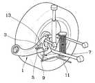
Translated fromKorean도 1은 본 발명에 따른 가변 범프 토우인 리어 서스펜션을 설명한 도면,1 is a view illustrating a variable bump toe rear suspension according to the present invention;
도 2는 트레일링암과 스태빌라이저링크 및 서포트블록의 구조를 상세히 설명한 도면,2 is a view illustrating in detail the structure of a trailing arm, a stabilizer link, and a support block;
도 3은 도 2의 상측에서 관측한 도면,3 is a view observed from the upper side of FIG.
도 4는 도 2의 Ⅳ??Ⅳ선 단면도,4 is a cross-sectional view taken along line IV ?? IV of FIG. 2;
도 5는 도 2와 비교한 차량의 롤거동시의 상태를 설명한 도면,5 is a view illustrating a state at the time of roll behavior of the vehicle compared to FIG. 2;
도 6은 서포트블록의 다른 실시예를 설명한 도면이다.6 is a view for explaining another embodiment of the support block.
<도면의 주요 부분에 대한 부호의 간단한 설명><Brief description of symbols for the main parts of the drawings>
1; 트레일링암 3; 서포트블록One;
5; 제1조인트 7; 스태빌라이저링크5;
9; 제2조인트 11; 스태빌라이저바9;
13; 서포트접촉부13; Support contact
본 발명은 휠의 범프 토우인이 차량의 주행상태에 따라서 가변되는 리어 서스펜션에 관한 것으로서, 보다 상세하게는 패널형 트레일링암을 구비한 현가장치에서 좌우차륜의 동상 거동시와 좌우 역상 거동시에 서로 다른 범프 토우인이 형성되도록 하는 기술에 관한 것이다.The present invention relates to a rear suspension in which the bump toe of the wheel is varied according to the driving state of the vehicle. It relates to a technique for forming a toe-in.
패널형 트레일링암은 자체의 굽힘강성에 따라서 후륜의 범프 토우인 값이 변화한다. 즉, 후륜의 범프시 트레일링암 자체의 차량 횡방향 변형이 범프 토우인 값에 영향을 주는 것이다. 이와 같은 패널형 트레일링암이 적용된 기존의 후륜현가장치에서는 현가장치의 지오메트리와 휠얼라인먼트를 후륜 범프시 상기 패널형 트레일링암에 횡력이 작용하도록 설계하고 있다.The panel trailing arm changes the bump toe of the rear wheel according to its bending stiffness. That is, the vehicle lateral deformation of the trailing arm itself during the bumping of the rear wheels affects the bump toe value. In the conventional rear wheel suspension device to which the panel trailing arm is applied, the geometry and the wheel alignment of the suspension system are designed to have a lateral force act on the panel trailing arm when the rear wheel bumps.
한편, 차량의 롤 거동을 제한하기 위한 스태빌라이저바는 조인트를 통해 스태빌라이저링크에 연결되고, 상기 스태빌라이저링크는 트레일링암 또는 너클 등에 조인트를 통해 장착된다.On the other hand, the stabilizer bar for limiting the roll behavior of the vehicle is connected to the stabilizer link through a joint, the stabilizer link is mounted via a joint to a trailing arm or knuckle.
본 발명은 상기 스태빌라이저링크가 패널형 트레일링암에 조인트를 매개로 장착된 구조를 그 기초로 한다.The present invention is based on a structure in which the stabilizer link is mounted to the panel trailing arm via a joint.
한편, 차량의 주행특성에 관하여 살펴보면, 차량의 선회 주행시에는 범프 토우인의 양이 큰 것이 타이어의 접지력 측면에서 유리하며, 차량의 직진 주행시에는 범프 토우인의 양이 작은 것이 차량의 직진 안정성의 측면에 유리하다.On the other hand, in terms of the driving characteristics of the vehicle, the amount of bump toe-in is advantageous in terms of tire grip when turning the vehicle, and the amount of bump-toe-in is advantageous in terms of the straight stability of the vehicle when the vehicle is traveling straight. Do.
차량의 선회 주행시에는 양쪽 차륜이 역상으로 거동하는 차량의 롤이 발생하므로, 양쪽 차륜이 역상으로 거동하는 차량의 롤 거동시에는 범프 토우인의 양이 큰 것이 유리하고, 주로 양쪽 차륜이 동상으로 상하로 거동하는 차량의 직진 주행시에는 범프 토우인의 양이 작은 것이 유리하다.Rolling of the vehicle generates a roll of a vehicle in which both wheels move in reverse, so that a large amount of bump toe is advantageous in a roll behavior of a vehicle in which both wheels move in reverse. It is advantageous that the amount of bump toe-in is small when driving straight in a moving vehicle.
본 발명은 양쪽 차륜이 역상으로 거동하는 경우에는 선회시에는 범프 토우인의 양을 비교적 크게 형성하도록 하고, 양쪽 차륜이 동상으로 거동하는 경우에는 직진 주행중 둔턱을 넘는 경우에는 범프 토우인의 양을 비교적 작게 형성하도록 하여, 차량의 선회 주행시나 직진 주행시에 각각 적절한 범프 토우인의 상태를 구현하여 차량 주행 안정성을 향상시킬 수 있도록 한 가변 범프 토우인 리어 서스펜션을 제공함에 그 목적이 있다.According to the present invention, when both wheels move in reverse, the amount of bump toe-in is relatively large when turning, and when both wheels are in phase, the amount of bump-toe-in is relatively small when the wheels exceed the threshold while driving straight. Accordingly, an object of the present invention is to provide a rear bump that is a variable bump toe which can improve vehicle driving stability by implementing a proper bump toe state when turning a vehicle or driving straight.
상기한 바와 같은 목적을 달성하기 위한 본 발명 가변 범프 토우인 리어 서스펜션은The present invention, the variable bump toe rear suspension for achieving the above object is
트레일링암에 차체의 내측을 향하여 돌출되게 형성된 서포트블록과;A support block formed on the trailing arm to protrude toward the inside of the vehicle body;
상기 트레일링암의 차체 내측에 유니버설조인트 타입의 부싱으로 결합되는 스태빌라이저링크와;A stabilizer link coupled to a bushing of a universal joint type inside the vehicle body of the trailing arm;
상기 스태빌라이저링크에 볼조인트로 연결되는 스태빌라이저바;A stabilizer bar connected to the stabilizer link by a ball joint;
를 포함하여 구성되고;It is configured to include;
상기 스태빌라이저링크에는 상기 스태빌라이저바에 비틀림토크가 작용되지 않는 상태에서 상기 서포트블록의 차체 내측면에 접촉하는 서포트접촉부가 구비된 것The stabilizer link is provided with a support contact portion for contacting the inner surface of the vehicle body of the support block in the state that the torsion torque is not applied to the stabilizer bar
을 특징으로 한다.It is characterized by.
이하, 첨부된 도면을 참조하여 본 발명의 바람직한 실시예를 설명하면 다음과 같다.Hereinafter, exemplary embodiments of the present invention will be described with reference to the accompanying drawings.
도 1 내지 도 4를 참조하면, 트레일링암(1)에 차체의 내측을 향하여 돌출되게 형성된 서포트블록(3)과; 상기 트레일링암(1)의 차체 내측에 제1조인트(5)로 결 합되는 스태빌라이저링크(7)와; 상기 스태빌라이저링크(7)에 제2조인트(9)로 연결되는 스태빌라이저바(11)를 포함한 구성이다.1 to 4, a
상기 스태빌라이저링크(7)에는 상기 스태빌라이저바(11)에 비틀림토크가 작용되지 않는 상태에서 상기 서포트블록(3)의 차체 내측면에 접촉하는 서포트접촉부(13)가 구비되어 있다.
여기서, 상기 제1조인트(5)는 유니버설 조인트의 특성을 가진 부싱을 사용하여 횡력에 대항할 수 있도록 되어 있어 스태빌라이저링크(7)의 서포트접촉부(13)가 서포트블록(3)에 대해서 횡방향으로 회전하여 이격되지 않도록 되어 있으며, 상기 제2조인트(9)는 볼조인트를 사용하여 정상적인 스태빌라이저바(11)의 작동이 가능하도록 되어 있다.The
Here, the first joint (5) is able to counter the lateral force by using a bushing having the characteristics of the universal joint so that the
상기 서포트블록(3)은 상기 제1조인트(5)로부터 멀어질수록 상기 서포트접촉부(13)와 접촉 가능한 면적이 넓어지도록 형성되는 바, 본 실시예에서는 상기 제1조인트(5)로부터 멀어질수록 폭이 넓어지는 사다리꼴로 형성되도록 하였다.The
상기 서포트블록(3)은 상기 서포트접촉부(13)와 접촉 가능한 부분의 상하 양측으로 그 폭이 점차 넓어지는 경사면을 구비하고 있어서, 결과적으로는 상기 서포트블록(3)의 단면 형상도 상기 제1포인트로부터 멀어질수록 상하방향 폭이 넓어지는 사다리꼴 단면이 된다.The
한편, 도 6은 상기 서포트블록(3)의 또 다른 실시예를 도시한 것으로서, 상기 트레일링암(1)에 접하는 현과 상기 현의 양단을 잇는 호로 이루어진 단면이 상기 제1조인트(5)로부터 멀어질수록 상하방향 폭이 확대되는 형상으로 구성할 수도 있다.Meanwhile, FIG. 6 shows another embodiment of the
이하에서는 상기 사다리꼴 단면 형상의 서포트블록(3)의 실시예를 도시하고 있는 도 1 내지 도 5를 기준으로 본 발명의 작용을 설명한다.Hereinafter, the operation of the present invention will be described with reference to FIGS. 1 to 5, which show an embodiment of the trapezoidal
선회 주행시와 같이 한쪽 차륜이 하측으로 이동하고 다른쪽 차륜은 상측으로 이동하는 차량의 롤 거동시에는 상기 스태빌라이저바(11)에 양쪽의 스태빌라이 저링크(7)를 통해 스태빌라이저바(11)에 비틀림토크가 작용한다.As in the case of turning driving, when one wheel moves downward and the other wheel moves upward, the stabilizer bar 11 twists to the
이와 같이 스태빌라이저바(11)에 비틀림토크가 작용할 때에는 스태빌라이저바(11) 양쪽의 스태빌라이저링크(7)가 각각 상측과 하측으로 회동되는 상태로서, 상기와 같이 스태빌라이저링크(7)가 회동되면, 상기 스태빌라이저링크(7)의 서포트접촉부(13)는 도 5에 도시된 바와 같이 서포트블록(3)으로부터 이격된다.When the torsion torque acts on the
따라서, 스태빌라이저링크(7)와 트레일링암(1)의 사이에는 상기 제1조인트(5)를 통해서만 연결된 구조가 되며, 이 상태에서는 상기 트레일링암(1)은 자체의 굽힘강성을 보강해주는 구조가 없으므로 선회주행시 발생하는 횡력과 기설정된 후륜현가장치의 지오메트리 및 휠얼라인먼트에 의해 트레일링암(1)에 발생되는 횡력에 의해 비교적 크게 차량의 횡방향으로 굽혀지면서 범프 토우인의 양을 비교적 크게 형성하게 되고, 이는 타이어의 접지력을 향상시켜 차량의 우수한 선회주행 성능을 발휘시켜준다.Therefore, between the
이와 비교하여, 차량의 직진 주행중 둔턱을 지나는 경우와 같이 양쪽 차륜이 동상으로 상하 거동하는 경우에는, 스태빌라이저바(11)에는 비틀림토크가 작용하지 않고, 상기 스태빌라이저바(11)와 트레일링암(1)을 연결하는 스태빌라이저링크(7)는 트레일링암(1)과 함께 거동하게 되므로 도 2와 같은 상태를 지속적으로 유지하게 된다.On the other hand, when both wheels move up and down in phase as in the case of passing through a barrier during the straight traveling of the vehicle, the torsion torque does not act on the
상기 도 2와 같은 상태에서는, 상기 스태빌라이저링크(7)의 서포트접촉부(13)가 상기 서포트블록(3)에 접촉하고 있어서, 스태빌라이저바(11)가 상기 서포트블록(3)을 통해 상기 트레일링암(1)을 지지하는 역할을 한다.In the state as shown in FIG. 2, the
따라서, 직진 주행중 둔턱을 넘어 범프가 발생할시 기설정된 후륜현가장치의 지오메트리 및 휠얼라인먼트에 의해 트레일링암(1)에 횡력이 발생하여도 상기 트레일링암(1)은 서포트블록(3)과 서포트접촉부(13)의 접촉상태에 의해 횡방향 굽힘강성이 보강되어 있으므로, 차륜 범프시 비교적 적은 양만 굽혀져서 범프 토우인의 양도 비교적 작게 형성되므로, 차량의 직진 안정성을 확보할 수 있도록 해준다.Accordingly, even when a lateral force is generated by the geometry and wheel alignment of the rear wheel suspension device, the
이상과 같이 본 발명에 의하면, 트레일링암에 구비된 서포트블록과 상기 서포트블록에의 접촉 상태가 가변되는 스태빌라이저링크를 구비하여, 양쪽 차륜이 역상으로 거동하는 선회 주행의 경우에는 범프 토우인의 양을 비교적 크게 형성하도록 하고, 양쪽 차륜이 동상으로 거동하는 직진 주행중 둔턱을 넘는 경우에는 범프 토우인의 양을 비교적 작게 형성하도록 함으로써, 차량의 선회 주행시나 직진 주행시에 각각 적절한 범프 토우인의 상태를 구현하여 차량 주행의 안정성을 향상시킨다.As described above, according to the present invention, a support block provided in the trailing arm and a stabilizer link having a variable contact state with the support block are provided. When the two wheels exceed the threshold during straight driving, in which the two wheels are in phase, the amount of bump toe is made relatively small. Improve stability.
Claims (5)
Translated fromKoreanPriority Applications (4)
| Application Number | Priority Date | Filing Date | Title |
|---|---|---|---|
| KR1020040096419AKR100610117B1 (en) | 2004-11-23 | 2004-11-23 | Variable bump toe-in rear suspension |
| JP2005213316AJP4755459B2 (en) | 2004-11-23 | 2005-07-22 | Variable toria suspension |
| DE102005039653ADE102005039653B4 (en) | 2004-11-23 | 2005-08-22 | Rear suspension with variable track |
| US11/285,468US7401797B2 (en) | 2004-11-23 | 2005-11-22 | Variable toe rear suspension |
Applications Claiming Priority (1)
| Application Number | Priority Date | Filing Date | Title |
|---|---|---|---|
| KR1020040096419AKR100610117B1 (en) | 2004-11-23 | 2004-11-23 | Variable bump toe-in rear suspension |
Publications (2)
| Publication Number | Publication Date |
|---|---|
| KR20060057311A KR20060057311A (en) | 2006-05-26 |
| KR100610117B1true KR100610117B1 (en) | 2006-08-09 |
Family
ID=36460236
Family Applications (1)
| Application Number | Title | Priority Date | Filing Date |
|---|---|---|---|
| KR1020040096419AExpired - Fee RelatedKR100610117B1 (en) | 2004-11-23 | 2004-11-23 | Variable bump toe-in rear suspension |
Country Status (4)
| Country | Link |
|---|---|
| US (1) | US7401797B2 (en) |
| JP (1) | JP4755459B2 (en) |
| KR (1) | KR100610117B1 (en) |
| DE (1) | DE102005039653B4 (en) |
Families Citing this family (21)
| Publication number | Priority date | Publication date | Assignee | Title |
|---|---|---|---|---|
| US7819220B2 (en) | 2006-07-28 | 2010-10-26 | Polaris Industries Inc. | Side-by-side ATV |
| US8596398B2 (en) | 2007-05-16 | 2013-12-03 | Polaris Industries Inc. | All terrain vehicle |
| KR100916794B1 (en)* | 2008-07-10 | 2009-09-14 | 현대자동차주식회사 | Active Control Suspension System |
| JP5182650B2 (en)* | 2009-03-30 | 2013-04-17 | スズキ株式会社 | Trailing arm suspension |
| US8613335B2 (en) | 2010-08-03 | 2013-12-24 | Polaris Industries Inc. | Side-by-side vehicle |
| US8746719B2 (en) | 2010-08-03 | 2014-06-10 | Polaris Industries Inc. | Side-by-side vehicle |
| KR101596691B1 (en)* | 2010-11-30 | 2016-02-23 | 현대자동차주식회사 | Link structure for controlling toe of rear wheel suspension |
| NL2006484C2 (en)* | 2011-03-29 | 2012-10-02 | Transp Industry Dev Ct Bv | TRAILER FOR A TRUCK COMBINATION, AND WHEEL SUSPENSION FOR SUCH TRAILER. |
| DE102013202527A1 (en)* | 2013-02-15 | 2014-08-21 | Bayerische Motoren Werke Aktiengesellschaft | Rear axle of a two-lane vehicle |
| JP6195069B2 (en)* | 2014-03-18 | 2017-09-13 | マツダ株式会社 | Mounting structure for vehicle suspension |
| CN104325858B (en)* | 2014-11-13 | 2017-07-28 | 郑州宇通客车股份有限公司 | A kind of vehicle and its active lateral stabilising arrangement |
| MX2017014403A (en) | 2015-05-15 | 2018-04-11 | Polaris Inc | UTILITY VEHICLE. |
| USD787985S1 (en) | 2015-06-24 | 2017-05-30 | Polaris Industries Inc. | All-terrain vehicle |
| US9649928B2 (en) | 2015-06-25 | 2017-05-16 | Polaris Industries Inc. | All-terrain vehicle |
| US9884647B2 (en) | 2015-12-10 | 2018-02-06 | Polaris Industries Inc. | Utility vehicle |
| US10723190B2 (en) | 2016-11-29 | 2020-07-28 | Zhejiang CFMOTO Power Co., Ltd. | Rear swing arm suspension |
| CN206765730U (en) | 2017-02-24 | 2017-12-19 | 浙江春风动力股份有限公司 | A kind of beach buggy and its rear arm bearing Mounting device |
| US10822037B2 (en) | 2017-11-15 | 2020-11-03 | Zhejiang CFMOTO Power Co., Ltd. | Frame structure for off road vehicle |
| US10946736B2 (en) | 2018-06-05 | 2021-03-16 | Polaris Industries Inc. | All-terrain vehicle |
| US12187127B2 (en) | 2020-05-15 | 2025-01-07 | Polaris Industries Inc. | Off-road vehicle |
| MX2023006716A (en) | 2022-06-13 | 2023-12-14 | Polaris Inc | POWER TRAIN FOR UTILITY VEHICLE. |
Citations (1)
| Publication number | Priority date | Publication date | Assignee | Title |
|---|---|---|---|---|
| JPS61278410A (en) | 1985-06-03 | 1986-12-09 | Honda Motor Co Ltd | Independent rear suspension |
Family Cites Families (35)
| Publication number | Priority date | Publication date | Assignee | Title |
|---|---|---|---|---|
| US2607610A (en)* | 1946-12-28 | 1952-08-19 | William D Allison | Spring suspension for motor vehicles |
| FR1237549A (en)* | 1958-10-18 | 1960-07-29 | Daimler Benz Ag | Elastic suspension of a rigid axle for vehicles, in particular for motor cars |
| US3029091A (en)* | 1959-11-16 | 1962-04-10 | Ford Motor Co | Vehicle suspension having u-shaped torsion bar |
| US2988374A (en)* | 1960-06-24 | 1961-06-13 | Elmo N Boyles | Kenee-action dead axle wheel suspension |
| US3195670A (en)* | 1962-08-17 | 1965-07-20 | Ford Motor Co | Torsion bar vehicle suspension |
| DE1630279A1 (en)* | 1967-04-29 | 1971-06-16 | Daimler Benz Ag | Wheel suspension for motor vehicles |
| DE2649990C2 (en)* | 1976-10-30 | 1985-10-17 | Daimler-Benz Ag, 7000 Stuttgart | Independent wheel suspension for motor vehicles |
| US4203615A (en)* | 1978-09-18 | 1980-05-20 | General Motors Corporation | Automotive vehicle suspension |
| US4542920A (en)* | 1982-07-07 | 1985-09-24 | Mazda Motor Corporation | Vehicle rear-suspension mechanism |
| JPS598511A (en)* | 1982-07-07 | 1984-01-17 | Mazda Motor Corp | Rear suspension of automobile |
| US4652009A (en)* | 1984-07-31 | 1987-03-24 | Mazda Motor Corporation | Rear suspension system for vehicle |
| GB8521143D0 (en)* | 1985-08-23 | 1985-10-02 | Gkn Technology Ltd | Vehicle suspension |
| JPH0537683Y2 (en)* | 1986-05-27 | 1993-09-24 | ||
| JPS6331812A (en)* | 1986-07-25 | 1988-02-10 | Mazda Motor Corp | Suspension device for automobile |
| JPH0775929B2 (en)* | 1988-07-28 | 1995-08-16 | マツダ株式会社 | Vehicle suspension system |
| US5102160A (en)* | 1990-11-28 | 1992-04-07 | General Motors Corporation | Connector assembly for a stabilizer bar |
| US5186486A (en)* | 1991-07-19 | 1993-02-16 | General Motors Corporation | Active link for a stabilizer bar |
| DE4330103C2 (en)* | 1992-09-22 | 1998-09-10 | Suzuki Motor Co | Suspension arm for the suspension of a motor vehicle |
| JPH0699709A (en)* | 1992-09-22 | 1994-04-12 | Suzuki Motor Corp | Automotive suspension |
| SE508519C2 (en)* | 1994-06-28 | 1998-10-12 | Volvo Ab | Wheel suspension for a pair of driven vehicle wheels |
| US5468018A (en)* | 1994-09-27 | 1995-11-21 | Chrysler Corporation | Torque box assembly for a vehicle |
| US5678845A (en)* | 1996-01-29 | 1997-10-21 | Reyco Industries, Inc. | Stabilizer for a steer axle air ride suspension of a vehicle |
| US5810383A (en)* | 1996-12-23 | 1998-09-22 | Anderson; Carey C. | Suspension and steering linkage for a tricycle |
| MY118375A (en)* | 1997-03-21 | 2004-10-30 | Honda Motor Co Ltd | Wheel suspension system |
| JP3716610B2 (en)* | 1998-03-30 | 2005-11-16 | マツダ株式会社 | Car rear wheel suspension system |
| ES2207938T3 (en)* | 1999-03-02 | 2004-06-01 | Zf Lemforder Metallwaren Ag | SUSPENSION OF AXIS OF RIGID AXLES. |
| KR100335957B1 (en)* | 1999-11-25 | 2002-05-10 | 이계안 | Multi camber suspension for vehicle |
| US6648350B1 (en)* | 2000-05-08 | 2003-11-18 | Meritor Light Vehicle Systems, Inc. | Suspension system for a vehicle having a vehicle stabilizer bar with integral end links |
| US6533301B1 (en)* | 2000-07-01 | 2003-03-18 | Meritor Suspension Systems Company | Stabilizer bar direct connect insert |
| JP3963069B2 (en)* | 2000-08-02 | 2007-08-22 | マツダ株式会社 | Rear suspension structure for vehicles |
| US20020074761A1 (en)* | 2000-12-14 | 2002-06-20 | Kincaid Jeffrey Lee | Robust, low mass stabilizer bar link assembly |
| US6530586B2 (en)* | 2001-03-13 | 2003-03-11 | Meritor Light Vehicle Systems Llc | Suspension torsion bar with variable rate adjustment arms |
| US6905130B2 (en)* | 2002-06-24 | 2005-06-14 | Norco Industries, Inc. | Torsion axle |
| JP2004098874A (en)* | 2002-09-10 | 2004-04-02 | Horikiri:Kk | Stabilizer and air leaf suspension using the same |
| US7052025B2 (en)* | 2003-08-28 | 2006-05-30 | General Motors Corporation | Apparatus for preloading a torsion bar |
- 2004
- 2004-11-23KRKR1020040096419Apatent/KR100610117B1/ennot_activeExpired - Fee Related
- 2005
- 2005-07-22JPJP2005213316Apatent/JP4755459B2/ennot_activeExpired - Fee Related
- 2005-08-22DEDE102005039653Apatent/DE102005039653B4/ennot_activeExpired - Fee Related
- 2005-11-22USUS11/285,468patent/US7401797B2/ennot_activeExpired - Fee Related
Patent Citations (1)
| Publication number | Priority date | Publication date | Assignee | Title |
|---|---|---|---|---|
| JPS61278410A (en) | 1985-06-03 | 1986-12-09 | Honda Motor Co Ltd | Independent rear suspension |
Also Published As
| Publication number | Publication date |
|---|---|
| DE102005039653B4 (en) | 2009-09-24 |
| US20060108762A1 (en) | 2006-05-25 |
| DE102005039653A1 (en) | 2006-06-01 |
| US7401797B2 (en) | 2008-07-22 |
| JP4755459B2 (en) | 2011-08-24 |
| JP2006143174A (en) | 2006-06-08 |
| KR20060057311A (en) | 2006-05-26 |
Similar Documents
| Publication | Publication Date | Title |
|---|---|---|
| KR100610117B1 (en) | Variable bump toe-in rear suspension | |
| US7407174B2 (en) | Suspension system for vehicle | |
| WO2012001933A1 (en) | Vehicle suspension apparatus | |
| WO2012001934A1 (en) | Vehicle suspension apparatus | |
| JP2007230517A (en) | Vehicle suspension system | |
| JP2008302813A (en) | Strut suspension system | |
| KR100335957B1 (en) | Multi camber suspension for vehicle | |
| KR100610110B1 (en) | Suspension System with Automatic Toe Control | |
| KR100667431B1 (en) | Lateral links for vehicle suspension | |
| KR100748762B1 (en) | Ball joint structure between vehicle lower arm and steering knuckle | |
| KR100811933B1 (en) | Coupled Torsion Beam Axle Suspension | |
| KR100462242B1 (en) | torsion beam suspension | |
| JP4011868B2 (en) | Independent suspension | |
| KR20010018375A (en) | Multi camber mode suspension | |
| KR100857361B1 (en) | Car Geometry Control | |
| KR101154572B1 (en) | suspension system with stability of straight and turning drive | |
| KR100462243B1 (en) | torsion beam suspension | |
| JP5267168B2 (en) | Suspension device | |
| JP2012071741A (en) | Suspension device | |
| KR100579734B1 (en) | Link structure of automobile suspension | |
| KR20110027227A (en) | Caster variable suspension of vehicle | |
| KR200260742Y1 (en) | An axle suspension system for automobile | |
| JP2007168753A (en) | Strut suspension system | |
| KR20090062654A (en) | Multi-Link Suspension in Cars | |
| KR20140072521A (en) | Variable arm |
Legal Events
| Date | Code | Title | Description |
|---|---|---|---|
| A201 | Request for examination | ||
| PA0109 | Patent application | St.27 status event code:A-0-1-A10-A12-nap-PA0109 | |
| PA0201 | Request for examination | St.27 status event code:A-1-2-D10-D11-exm-PA0201 | |
| D13-X000 | Search requested | St.27 status event code:A-1-2-D10-D13-srh-X000 | |
| D14-X000 | Search report completed | St.27 status event code:A-1-2-D10-D14-srh-X000 | |
| E902 | Notification of reason for refusal | ||
| PE0902 | Notice of grounds for rejection | St.27 status event code:A-1-2-D10-D21-exm-PE0902 | |
| P11-X000 | Amendment of application requested | St.27 status event code:A-2-2-P10-P11-nap-X000 | |
| P13-X000 | Application amended | St.27 status event code:A-2-2-P10-P13-nap-X000 | |
| PG1501 | Laying open of application | St.27 status event code:A-1-1-Q10-Q12-nap-PG1501 | |
| E701 | Decision to grant or registration of patent right | ||
| PE0701 | Decision of registration | St.27 status event code:A-1-2-D10-D22-exm-PE0701 | |
| GRNT | Written decision to grant | ||
| PR0701 | Registration of establishment | St.27 status event code:A-2-4-F10-F11-exm-PR0701 | |
| PR1002 | Payment of registration fee | St.27 status event code:A-2-2-U10-U11-oth-PR1002 Fee payment year number:1 | |
| PG1601 | Publication of registration | St.27 status event code:A-4-4-Q10-Q13-nap-PG1601 | |
| R18-X000 | Changes to party contact information recorded | St.27 status event code:A-5-5-R10-R18-oth-X000 | |
| PR1001 | Payment of annual fee | St.27 status event code:A-4-4-U10-U11-oth-PR1001 Fee payment year number:4 | |
| PN2301 | Change of applicant | St.27 status event code:A-5-5-R10-R13-asn-PN2301 St.27 status event code:A-5-5-R10-R11-asn-PN2301 | |
| PR1001 | Payment of annual fee | St.27 status event code:A-4-4-U10-U11-oth-PR1001 Fee payment year number:5 | |
| PR1001 | Payment of annual fee | St.27 status event code:A-4-4-U10-U11-oth-PR1001 Fee payment year number:6 | |
| FPAY | Annual fee payment | Payment date:20120731 Year of fee payment:7 | |
| PR1001 | Payment of annual fee | St.27 status event code:A-4-4-U10-U11-oth-PR1001 Fee payment year number:7 | |
| PN2301 | Change of applicant | St.27 status event code:A-5-5-R10-R13-asn-PN2301 St.27 status event code:A-5-5-R10-R11-asn-PN2301 | |
| FPAY | Annual fee payment | Payment date:20130731 Year of fee payment:8 | |
| PR1001 | Payment of annual fee | St.27 status event code:A-4-4-U10-U11-oth-PR1001 Fee payment year number:8 | |
| PR1001 | Payment of annual fee | St.27 status event code:A-4-4-U10-U11-oth-PR1001 Fee payment year number:9 | |
| FPAY | Annual fee payment | Payment date:20150731 Year of fee payment:10 | |
| PR1001 | Payment of annual fee | St.27 status event code:A-4-4-U10-U11-oth-PR1001 Fee payment year number:10 | |
| R18-X000 | Changes to party contact information recorded | St.27 status event code:A-5-5-R10-R18-oth-X000 | |
| FPAY | Annual fee payment | Payment date:20160729 Year of fee payment:11 | |
| PR1001 | Payment of annual fee | St.27 status event code:A-4-4-U10-U11-oth-PR1001 Fee payment year number:11 | |
| LAPS | Lapse due to unpaid annual fee | ||
| PC1903 | Unpaid annual fee | St.27 status event code:A-4-4-U10-U13-oth-PC1903 Not in force date:20170802 Payment event data comment text:Termination Category : DEFAULT_OF_REGISTRATION_FEE | |
| PC1903 | Unpaid annual fee | St.27 status event code:N-4-6-H10-H13-oth-PC1903 Ip right cessation event data comment text:Termination Category : DEFAULT_OF_REGISTRATION_FEE Not in force date:20170802 | |
| R18-X000 | Changes to party contact information recorded | St.27 status event code:A-5-5-R10-R18-oth-X000 |