KR100608109B1 - Apparatus and method for calculating Doppler frequency and moving speed in mobile communication system - Google Patents
Apparatus and method for calculating Doppler frequency and moving speed in mobile communication systemDownload PDFInfo
- Publication number
- KR100608109B1 KR100608109B1KR1020040049063AKR20040049063AKR100608109B1KR 100608109 B1KR100608109 B1KR 100608109B1KR 1020040049063 AKR1020040049063 AKR 1020040049063AKR 20040049063 AKR20040049063 AKR 20040049063AKR 100608109 B1KR100608109 B1KR 100608109B1
- Authority
- KR
- South Korea
- Prior art keywords
- signals
- signal
- band
- search
- doppler frequency
- Prior art date
- Legal status (The legal status is an assumption and is not a legal conclusion. Google has not performed a legal analysis and makes no representation as to the accuracy of the status listed.)
- Expired - Fee Related
Links
Images


Classifications
- G—PHYSICS
- G01—MEASURING; TESTING
- G01S—RADIO DIRECTION-FINDING; RADIO NAVIGATION; DETERMINING DISTANCE OR VELOCITY BY USE OF RADIO WAVES; LOCATING OR PRESENCE-DETECTING BY USE OF THE REFLECTION OR RERADIATION OF RADIO WAVES; ANALOGOUS ARRANGEMENTS USING OTHER WAVES
- G01S13/00—Systems using the reflection or reradiation of radio waves, e.g. radar systems; Analogous systems using reflection or reradiation of waves whose nature or wavelength is irrelevant or unspecified
- G01S13/02—Systems using reflection of radio waves, e.g. primary radar systems; Analogous systems
- G01S13/50—Systems of measurement based on relative movement of target
- G01S13/52—Discriminating between fixed and moving objects or between objects moving at different speeds
- G01S13/522—Discriminating between fixed and moving objects or between objects moving at different speeds using transmissions of interrupted pulse modulated waves
- G01S13/524—Discriminating between fixed and moving objects or between objects moving at different speeds using transmissions of interrupted pulse modulated waves based upon the phase or frequency shift resulting from movement of objects, with reference to the transmitted signals, e.g. coherent MTi
- G01S13/53—Discriminating between fixed and moving objects or between objects moving at different speeds using transmissions of interrupted pulse modulated waves based upon the phase or frequency shift resulting from movement of objects, with reference to the transmitted signals, e.g. coherent MTi performing filtering on a single spectral line and associated with one or more range gates with a phase detector or a frequency mixer to extract the Doppler information, e.g. pulse Doppler radar
- H—ELECTRICITY
- H04—ELECTRIC COMMUNICATION TECHNIQUE
- H04L—TRANSMISSION OF DIGITAL INFORMATION, e.g. TELEGRAPHIC COMMUNICATION
- H04L27/00—Modulated-carrier systems
- H04L27/0014—Carrier regulation
- H—ELECTRICITY
- H04—ELECTRIC COMMUNICATION TECHNIQUE
- H04B—TRANSMISSION
- H04B7/00—Radio transmission systems, i.e. using radiation field
- H04B7/002—Reducing depolarization effects
- H—ELECTRICITY
- H04—ELECTRIC COMMUNICATION TECHNIQUE
- H04L—TRANSMISSION OF DIGITAL INFORMATION, e.g. TELEGRAPHIC COMMUNICATION
- H04L27/00—Modulated-carrier systems
- H04L27/0014—Carrier regulation
- H04L2027/0044—Control loops for carrier regulation
- H04L2027/0063—Elements of loops
- H04L2027/0065—Frequency error detectors
Landscapes
- Engineering & Computer Science (AREA)
- Computer Networks & Wireless Communication (AREA)
- Signal Processing (AREA)
- Radar, Positioning & Navigation (AREA)
- Remote Sensing (AREA)
- Physics & Mathematics (AREA)
- Spectroscopy & Molecular Physics (AREA)
- General Physics & Mathematics (AREA)
- Mobile Radio Communication Systems (AREA)
- Radar Systems Or Details Thereof (AREA)
Abstract
Translated fromKoreanDescription
Translated fromKorean도 1은 종래 기술에 따른 도플러 주파수 계산장치를 나타내는 블록도이다.1 is a block diagram showing a Doppler frequency calculating apparatus according to the prior art.
도 2는 본 발명의 제 1 실시예에 따른 도플러 주파수 계산장치를 나타내는 블록도이다.2 is a block diagram illustrating a Doppler frequency calculating device according to a first embodiment of the present invention.
도 3a 및 도 3b는 도 2의 도플러 주파수 계산장치 내에 있는 필터뱅크의 주파수 응답특성을 나타내는 도면이다.3A and 3B are diagrams illustrating frequency response characteristics of a filter bank in the Doppler frequency calculator of FIG.
도 4는 도 2의 도플러 주파수 계산장치 내에 있는 필터들의 일례로 FIR 필터를 나타내는 도면이다.4 is a diagram illustrating an FIR filter as an example of filters in the Doppler frequency calculator of FIG. 2.
도 5는 도 2의 도플러 주파수 계산장치 내에 있는 필터들의 일례로 IIR 필터를 나타내는 도면이다.5 is a diagram illustrating an IIR filter as an example of filters in the Doppler frequency calculator of FIG. 2.
도 6은 본 발명의 제 2 실시예에 따른 도플러 주파수 계산장치를 나타내는 블록도이다.6 is a block diagram illustrating a Doppler frequency calculator according to a second embodiment of the present invention.
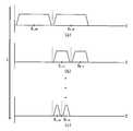
도 7은 도 6의 도플러 주파 계산장치를 사용하여 도플러 주파수를 계산하는 방법을 나타내는 도면이다.FIG. 7 is a diagram illustrating a method of calculating a Doppler frequency using the Doppler frequency calculator of FIG. 6.
*도면의 주요부분에 대한 부호의 설명** Description of the symbols for the main parts of the drawings *
100 : 필터뱅크100: filter bank
110, 120, 130, 140, 611, 613 : 대역통과필터110, 120, 130, 140, 611, 613: band pass filter
200, 620 : 비상관 누산기200, 620: uncorrelated accumulator
210, 621 : 제곱 연산부210, 621: square calculation unit
211, 213, 215, 217, 624, 625 : 제곱 연산기211, 213, 215, 217, 624, 625: Square operator
220, 623 : 누산부220, 623: Accumulation part
221, 223, 225, 227, 626, 627 : 누산기221, 223, 225, 227, 626, 627: accumulator
300 : 최대값 검출기300: maximum value detector
610 : 필터부610: filter unit
630 : 비교기630: comparator
640 : 검색 제어부640: search control
642 : 주파수 추적회로642: frequency tracking circuit
643 : 메모리643: memory
650 : 속도 계산부650 speed calculation unit
본 발명은 무선통신 시스템에 관한 것으로, 특히 무선통신 시스템에서 도플러 주파수 및 단말기의 이동속도를 계산하는 방법 및 장치에 관한 것이다.The present invention relates to a wireless communication system, and more particularly, to a method and apparatus for calculating a Doppler frequency and a moving speed of a terminal in a wireless communication system.
무선통신 시스템에서 신호의 전송채널은 시간에 따라 변화한다. 또한, 무선 통신 시스템에서 단말기의 이동속도의 변화에 따라 전송채널이 변화한다. 이것은 무선통신 시스템의 성능에 상당한 영향을 미친다. 일반적으로 이러한 효과를 도플러 주파수의 변화(Doppler Shift) 혹은 도플러 스프레드(Doppler Spread)라 부르며, 도플러 주파수의 변화량을 계산함으로써 단말기의 이동속도를 계산할 수 있다.In a wireless communication system, the transmission channel of a signal changes with time. In addition, in the wireless communication system, the transmission channel changes according to the change of the moving speed of the terminal. This has a significant impact on the performance of the wireless communication system. In general, such an effect is called a Doppler shift or a Doppler spread, and the moving speed of the terminal can be calculated by calculating the amount of change in the Doppler frequency.
도플러 주파수의 변화를 이용해서 단말기의 이동속도를 계산하면 다음과 같은 장점이 있다. 첫째, 수신 단말기의 복조성능 향상을 가져올 수 있다. 즉, 단말기의 속도를 측정함으로써 채널의 상황을 파악할 수 있기 때문에, 수신기에 사용되는 필터들의 채널 변화량에 따른 최적의 계수 값들을 실시간으로 구해서 복조과정에 반영할 수 있다. 둘째, 계층적 셀 구조를 갖는 시스템의 핸드오버(handover) 영역에서 단말기의 통화가 끊기는 현상을 예방할 수 있다. 즉, 고속으로 움직이는 단말기는 매크로 셀(Macro Cell)에 할당을 하고, 저속으로 움직이는 단말기는 마이크로 셀(Micro Cell)이나 피코 셀(Pico Cell)에 할당을 함으로써, 잦은 횟수의 핸드오버 현상을 방지할 수 있다. 셋째, 셀(Cell)의 자원관리 측면에서 고속 데이터 서비스는 저속의 단말기에 할당을 하고, 저속 데이터 서비스는 고속의 단말기에 할당할 수 있다.Calculating the moving speed of the terminal using the change of Doppler frequency has the following advantages. First, the demodulation performance of the receiving terminal can be improved. That is, since the state of the channel can be grasped by measuring the speed of the terminal, the optimum coefficient values according to the channel variation of the filters used in the receiver can be obtained in real time and reflected in the demodulation process. Second, the call disconnection of the terminal in the handover area of a system having a hierarchical cell structure can be prevented. That is, a terminal moving at high speed is allocated to a macro cell, and a terminal moving at low speed is assigned to a micro cell or a pico cell, thereby preventing frequent handovers. Can be. Third, in terms of resource management of a cell, a high speed data service may be allocated to a low speed terminal, and a low speed data service may be allocated to a high speed terminal.
도 1은 종래 기술에 따른 도플러 주파수 계산장치를 나타내는 블록도로서, Leonid Krasny 등에 의해 발명된 미국등록특허 6,563,861에 개시되어 있다. 도 1을 참조하면, 종래의 도플러 주파수 계산장치(20)는 승산기(multiplier)(26), 저역통과 필터(28), 프로세싱 블록(30), 프로세싱 블록(32), 및 최대 값 기능 블록(34)을 구비한다. 승산기(26)는 샘플된 수신신호들(rn)을 수신하고 이 신호들을 전송된 심벌의 복소공액(dn*)과 곱한다. 저역통과 필터(28)는 승산기(26)의 출력을 수신하고 전송된 심벌 계산값의 통계적 에러와 밴드 노이즈를 감소시키는 기능을 한다. 저역통과 필터(28)의 출력은 프로세싱 블록(30)에 입력된다. 프로세싱 블록(30)은 입력되는 신호의 스펙트럼 밀도(spectral density)를 계산한다. 프로세싱 블록(30)의 출력은 프로세싱 블록(32)에 입력된다. 프로세싱 블록(32)은 가능성 비 메트릭스(likelihood ratio metrics)를 발생시키는 다중 채널 코릴레이터(correlator)이다. 코릴레이터의 각 채널은 주파수 영역에서 스펙트럼 계산 값과 대기 함수(waiting function) 사이의 상관(correlation)을 계산한다. 가능성 비 메트릭스(likelihood ratio metrics)들은 서로 비교되고, 그 출력은 최대 값 기능 블록(34)에 입력된다. 가능성 비 메트릭스들 사이의 비교에 기초하여, m 번째 채널이 최대 출력 값을 갖는다면 프로세싱 블록(32)은 도플러 스프레드 fd(m)를 발생시킨다.1 is a block diagram showing a Doppler frequency calculating device according to the prior art, which is disclosed in US Patent No. 6,563,861 invented by Leonid Krasny et al. Referring to FIG. 1, a conventional
상기 특허는 FFT(Fast Fourier Transform)을 이용하여 수신신호의 스펙트럼을 구한 뒤 이를 도플러 스프레드(Doppler Spread) 신호들과 상관을 구하고 각 채널의 출력 값 중 가장 큰 값을 도플러 스프레드, 즉 도플러 주파수로서 출력한다.The patent obtains a spectrum of a received signal using a fast fourier transform (FFT) and then correlates it with Doppler Spread signals and outputs the largest value of each channel's output value as a Doppler spread, that is, a Doppler frequency. do.
Alexandre Mallette 등에 의해 발명된 미국등록특허 6,636,574에는 자기상관(autocorrelation) 또는 자기공분산(autocovariance) 방법을 이용해서 도플러 주파수 변이를 계산하는 방법이 개시되어 있다.U. S. Patent No. 6,636, 574, invented by Alexandre Mallette et al., Discloses a method for calculating Doppler frequency variation using an autocorrelation or autocovariance method.
그런데, 상기 특허들에서는 도플러 주파수를 구하기 위해 많은 연산량이 요구된다는 단점이 있다.However, the above patents have a disadvantage in that a large amount of calculation is required to obtain the Doppler frequency.
본 발명은 상술한 종래의 문제점을 해결하고자 고안된 발명으로서, 본 발명의 목적은 간단한 도플러 주파수 계산장치를 제공하는 것이다.The present invention has been made to solve the above-mentioned problems, and an object of the present invention is to provide a simple Doppler frequency calculating device.
본 발명의 다른 목적은 도플러 주파수 계산방법을 제공하는 것이다.Another object of the present invention is to provide a Doppler frequency calculation method.
본 발명의 또 다른 목적은 무선 단말기의 이동속도 계산장치를 제공하는 것이다.Still another object of the present invention is to provide an apparatus for calculating a moving speed of a wireless terminal.
본 발명의 또 다른 목적은 무선 단말기의 이동속도 계산방법을 제공하는 것이다.Still another object of the present invention is to provide a method of calculating a moving speed of a wireless terminal.
상기 목적을 달성하기 위하여 본 발명의 제 1 실시형태에 따른 도플러 주파수 및 단말기의 이동속도 계산장치는 필터뱅크, 비상관 누산기, 및 최대값 검출기를 구비한다. 필터뱅크는 복조신호들을 수신하여 대역별로 필터링하고 각 대역에 대응하는 복수의 필터링된 신호들을 발생시킨다. 비상관 누산기는 소정의 시간동안 입력된 데이터 블록에 대해 상기 복수의 필터링된 신호들 각각을 비상관 누적연산(non-coherent accumulation)하고 복수의 누적연산 신호들을 발생시킨다. 최대값 검출기는 상기 누적연산 신호들 중 가장 큰 값을 갖는 신호를 검출하고 이 신호에 대응하는 대역의 중심주파수를 도플러 주파수로 출력한다. 상기 복조신호들은 안테나로부터 수신된 신호들을 복조한 신호들이거나 일정한 패턴을 가지는 파일 럿 신호들을 복조한 신호들일 수 있다.In order to achieve the above object, the Doppler frequency and the moving speed calculating device of the terminal according to the first embodiment of the present invention includes a filter bank, an uncorrelated accumulator, and a maximum detector. The filter bank receives the demodulated signals, filters the bands, and generates a plurality of filtered signals corresponding to each band. An uncorrelated accumulator non-coherent accumulates each of the plurality of filtered signals for the input data block for a predetermined time and generates a plurality of cumulative computation signals. The maximum detector detects a signal having the largest value among the cumulative calculation signals and outputs the center frequency of the band corresponding to the signal as the Doppler frequency. The demodulated signals may be demodulated signals received from an antenna or demodulated pilot signals having a predetermined pattern.
상기 비상관 누산기는 상기 복수의 필터링된 신호들 각각을 제곱하고 복수의 제곱신호들을 출력하는 제곱 연산부, 및 소정의 시간동안 입력된 데이터 블록에 대해 상기 복수의 제곱신호들 각각을 누적연산하고 상기 복수의 누적연산 신호들을 출력하는 누산부를 구비한다.The non-correlated accumulator accumulates each of the plurality of filtered signals and outputs a plurality of squared signals, and accumulates each of the plurality of squared signals with respect to a data block input for a predetermined time. And an accumulating unit for outputting the cumulative calculation signals.
본 발명의 제 1 실시형태에 따른 도플러 주파수 및 단말기의 이동속도 계산장치에 있어서, 단말기의 이동속도를 Vd, 도플러 주파수를 fd, 캐리어 주파수를 fc, 및 전파의 속도를 C라 할 때, 단말기 이동속도는In the apparatus for calculating the Doppler frequency and the moving speed of a terminal according to the first embodiment of the present invention, when the moving speed of the terminal is Vd, the Doppler frequency is fd, the carrier frequency is fc, and the speed of the radio wave is C, the terminal is moved. Speed is

의 식에 의해 계산된다.Calculated by the formula
본 발명의 제 1 실시형태에 따른 도플러 주파수 및 단말기의 이동속도 계산방법은 복조신호들을 수신하여 대역별로 필터링하고 각 대역에 대응하는 복수의 필터링된 신호들을 발생시키는 단계, 소정의 시간동안 입력된 데이터 블록에 대해 상기 복수의 필터링된 신호들 각각을 비상관 누적연산(non-coherent accumulation)하고 복수의 누적 신호들을 발생시키는 단계, 및 상기 누적 신호들 중 가장 큰 값을 갖는 신호를 검출하고 이 신호에 대응하는 대역의 중심주파수를 도플러 주파수로 출력하는 단계를 구비한다.A method of calculating a Doppler frequency and a moving speed of a terminal according to a first embodiment of the present invention includes receiving demodulated signals, filtering each band, and generating a plurality of filtered signals corresponding to each band, and data input for a predetermined time. Non-coherent accumulating each of the plurality of filtered signals for a block and generating a plurality of cumulative signals, and detecting a signal having the largest value among the cumulative signals and applying to the signal. Outputting the center frequency of the corresponding band at the Doppler frequency.
본 발명의 제 2 실시형태에 따른 도플러 주파수 및 단말기의 이동속도 계산장치는 대역필터부, 비상관 누산기, 비교기, 및 검색제어부를 구비한다. 대역필터부는 설정된 2 분할 검색대역에 대해 복조신호를 각각 대역필터링하고 필터링된 신호쌍을 발생시킨다. 비상관 누산기는 상기 필터링된 신호쌍 각각을 소정 시간동안 비상관 누적연산하여 비상관 누적 신호쌍을 발생시킨다. 비교기는 상기 비상관 누적 신호쌍을 서로 비교하고 더 큰 값을 가진 신호를 검출신호로 발생시킨다. 검색제어부는 검색시작시 초기 2 분할 검색대역을 설정하고, 상기 2 분할 검색대역 중 상기 검출신호에 대응하는 분할대역을 다음 검색주기의 2 분할 검색대역으로 설정하기 위한 제어신호를 발생하여 상기 대역필터부에 제공하는 것을 소정 횟수의 검색주기 동안 검색대역을 좁혀가면서 반복하고, 최종 검색주기에 검출된 상기 검출신호를 찾고자 하는 도플러 주파수로 판단한다.The apparatus for calculating the Doppler frequency and the moving speed of the terminal according to the second embodiment of the present invention includes a band filter section, an uncorrelated accumulator, a comparator, and a search control section. The band filter unit band-filters the demodulated signal for each of the set two-division search bands and generates filtered signal pairs. An uncorrelated accumulator accumulates an uncorrelated cumulative operation on each of the filtered signal pairs for a predetermined time to generate an uncorrelated cumulative signal pair. A comparator compares the uncorrelated cumulative signal pairs with each other and generates a signal with a larger value as a detection signal. The search control unit sets the initial two-segment search band at the start of the search, generates a control signal for setting the divided band corresponding to the detection signal among the two-segment search bands to the two-segment search band of the next search period, and generates the band filter. The provision to the unit is repeated while the search band is narrowed for a predetermined number of search periods, and it is determined as the Doppler frequency to find the detected signal detected in the last search period.
본 발명의 제 2 실시형태에 따른 도플러 주파수 및 단말기의 이동속도 계산장치에 있어서, 단말기의 이동속도를 Vd, 도플러 주파수를 fd, 캐리어 주파수를 fc, 및 전파의 속도를 C라 할 때, 단말기 이동속도는In the apparatus for calculating the Doppler frequency and the moving speed of the terminal according to the second embodiment of the present invention, when the moving speed of the terminal is Vd, the Doppler frequency is fd, the carrier frequency is fc, and the propagation speed is C, the terminal is moved. Speed is

의 식에 의해 계산된다.Calculated by the formula
본 발명의 제 2 실시형태에 따른 도플러 주파수 및 단말기의 이동속도 계산방법은 설정된 2 분할 검색대역에 대해 복조신호를 각각 대역필터링하고 필터링된 신호쌍을 출력하는 단계, 상기 필터링된 신호쌍을 각 신호에 대해 소정 시간동안 비상관 누적연산하여 비상관 누적 신호쌍을 발생시키는 단계, 상기 비상관 누적 신호쌍을 서로 비교하고 더 큰 값을 가진 신호를 검출신호로 출력하는 단계, 검색시 작시 초기 2 분할 검색대역을 설정하고, 상기 2 분할 검색대역 중 상기 검출신호에 대응하는 분할대역을 다음 검색주기의 2 분할 검색대역으로 설정하기 위한 제어신호를 발생시키는 것을 소정 횟수의 검색주기 동안 검색대역을 좁혀가면서 반복하는 단계, 및 최종 검색주기에 검출된 상기 검출신호를 찾고자 하는 도플러 주파수로 판단하여 검색을 종료하는 단계를 구비한다.A method of calculating a Doppler frequency and a moving speed of a terminal according to a second embodiment of the present invention includes band-filtering a demodulated signal for a set two-division search band and outputting a filtered signal pair, respectively, and outputting the filtered signal pair to each signal. Generating uncorrelated cumulative signal pairs by performing uncorrelated cumulative operation for a predetermined time, comparing the uncorrelated cumulative signal pairs with each other and outputting a signal having a larger value as a detection signal; Setting the search band and generating a control signal for setting the divided band corresponding to the detection signal among the two divided search bands to the two divided search bands of the next search period while narrowing the search band for a predetermined number of search periods. Iterating, and determining the Doppler frequency to find the detected signal detected in the last search period to end the search Completing the process.
이하, 첨부한 도면을 참조하여 본 발명의 바람직한 실시예들을 설명한다.Hereinafter, exemplary embodiments of the present invention will be described with reference to the accompanying drawings.
도 2는 본 발명의 제 1 실시예에 따른 도플러 주파수 및 단말기의 이동속도 계산장치를 나타내는 블록도이다. 도 2를 참조하면, 도플러 주파수 계산장치는 필터뱅크(100), 비상관 누산기(non-coherent accumulator)(200), 및 최대값 검출기(300)를 구비한다. 필터뱅크(100)는 서로 다른 중심주파수들(f1 ~ fN)을 갖는 대역통과필터들(110, 120, 130, 140)로 구성되어 있다. 비상관 누산기(200)는 제곱 연산기들(211,213, 215, 217)로 구성된 제곱 연산부(210)와 누산기들(221, 223, 225, 227)로 구성된 누산부(220)를 구비한다. 필터뱅크(100)는 복조신호들(rk)을 수신하여 대역별로 필터링하고 각 대역에 대응하는 필터링된 신호들을 발생시킨다. 비상관 누산기(200)는 소정의 시간동안 입력된 데이터 블록에 대해 복수의 필터링된 신호들 각각을 비상관 누적연산하고 누적연산 신호들을 발생시킨다. 제곱 연산부(210)는 필터링된 신호들 각각을 제곱하고 제곱신호들을 출력한다. 누산부(220)는 소정의 시간동안 입력된 데이터 블록에 대해 상기 제곱신호들 각각을 누적연산하고 상기 누적연산 신호들을 출력한다. 최대값 검출기(300)는 누적연산 신호들 중 가장 큰 값을 갖는 신호를 검출하고 이 신호에 대응하는 대역의 중심주파수를 도플러 주파수(fd)로 출력한다.2 is a block diagram illustrating an apparatus for calculating a Doppler frequency and a moving speed of a terminal according to a first embodiment of the present invention. Referring to FIG. 2, the Doppler frequency calculator includes a
도 3a 및 도 3b는 도 2의 도플러 주파수 계산장치 내에 있는 필터뱅크의 주파수 응답특성을 나타내는 도면이다.3A and 3B are diagrams illustrating frequency response characteristics of a filter bank in the Doppler frequency calculator of FIG.
이하, 도 2, 도 3a, 및 도 3b를 참조하여 본 발명의 제 1 실시예에 따른 도플러 주파수 계산장치의 동작을 설명한다.Hereinafter, the operation of the Doppler frequency calculator according to the first embodiment of the present invention will be described with reference to FIGS. 2, 3A, and 3B.
대역통과 필터들(110, 120, 130, 140)은 각각 측정하고자 하는 각 도플러 주파수(f1 ~ fN)에 중심주파수가 맞추어져 있다. 도 2에서, 도플러 주파수 계산장치가 수신하는 신호는 안테나로부터 수신된 신호들을 복조한 신호들이거나 일정한 패턴을 가지는 파일럿 신호들을 복조한 신호들일 수 있다. 이러한 신호들은 무선 채널의 변화에 따라 도플러 변이(Doppler Shift)를 겪게 된다. 복조신호들(rk)은 서로 다른 중심주파수들(f1 ~ fN)을 갖는 대역통과필터들(110, 120, 130, 140)을 통해 대역별로 필터링된다. 서로 다른 중심주파수들(f1 ~ fN)을 갖는 대역통과필터들(110, 120, 130, 140)에 의해 필터링된 신호들은 비상관 누산기(200)에 의해 소정의 시간동안 입력된 데이터 블록에 대해 비상관 누적연산된다. 비상관 누산기(200)에 의해 누적된 값은 소정의 시간동안 평균된 값이다. 이와 같이 시간평균을 행하는 이유는 짧은 구간의 잡음에 대해 강인하게 만들기 위함이다. 따라서, 실제 신호가 통과한 무선채널의 도플러 주파수와 가장 가까운 중심주파수를 갖는 필터의 출력이 가장 크게 되며, 나머지 필터들의 출력은 상대적으로 작게 된다. 최대값 검출기(300)에 서는 비상관 누산기(200)의 출력들 중 가장 큰 값을 갖는 신호가 검출되고, 이 신호에 대응하는 대역통과필터의 중심주파수를 도플러 주파수로 출력한다.The bandpass filter (110, 120, 130, 140) has a center frequency as of the respective Doppler frequency (f1 ~ fN) to be measured, respectively. In FIG. 2, the signals received by the Doppler frequency calculator may be demodulated signals received from the antenna or demodulated pilot signals having a predetermined pattern. These signals undergo Doppler shift as the radio channel changes. The demodulated signals rk are filtered band by band through band pass filters 110, 120, 130, and 140 having different center frequencies f1 to fN. The signals filtered by the
도 3a는 에일리어싱(aliasing) 현상이 없을 경우, 필터뱅크의 주파수 응답특성을 나타내는 도면이고, 도 3b는 에일리어싱 현상이 있을 경우, 필터뱅크의 주파수 응답특성을 나타내는 도면이다. 도 3a를 참조하면, 필터뱅크는 서로 다른 중심주파수들(f1 ~ fN)을 갖는 N 개의 대역을 가진다. 도 3b를 참조하면, 필터뱅크는 서로 다른 중심주파수들(f1 ~ fN)을 갖는 N 개의 대역을 가지고, 대역들은 조금씩 겹쳐 있다. 도 2에 도시된 본 발명의 도플러 주파수 계산장치는 필터들의 출력의 상대적인 크기를 비교하는 것이므로, 도 3b에서와 같이 어느 정도의 에일리어싱 현상이 존재하더라도 도플러 주파수(fd)를 계산하는 데 큰 문제는 없다.3A is a diagram illustrating a frequency response characteristic of a filter bank when there is no aliasing phenomenon, and FIG. 3B is a diagram illustrating a frequency response characteristic of a filter bank when there is an aliasing phenomenon. Referring to FIG. 3A, the filter bank has N bands having different center frequencies f1 to fN. Referring to FIG. 3B, the filter bank has N bands having different center frequencies f1 to fN , and the bands overlap each other little by little. Since the Doppler frequency calculating device of the present invention shown in FIG. 2 compares the relative magnitudes of the outputs of the filters, there is no big problem in calculating the Doppler frequency fd even if some aliasing phenomenon exists as in FIG. 3B. .
도 2의 도플러 주파수 계산장치를 사용하여 도플러 주파수(fd)를 구한 다음 단말기의 이동속도는 수학식 1을 사용하여 구할 수 있다.After the Doppler frequency fd is obtained using the Doppler frequency calculator of FIG. 2, the moving speed of the terminal may be calculated using

수학식 1에서, Vd는 단말기의 이동속도를, fd는 도플러 주파수를, fc는 캐리어 주파수를, C는 전파의 속도(3×10⁸ m/s)를 나타낸다.In
도 4는 도 2의 도플러 주파수 계산장치 내에 있는 필터들의 일례로 FIR(Finite Impulse Response) 필터를 나타내는 도면이고, 도 5는 도 2의 도플러 주파수 계산장치 내에 있는 필터들의 일례로 IIR(Infinite Impulse Response) 필터를 나타내는 도면이다. 도 4와 도 5에 도시된 FIR 필터와 IIR 필터는 신호처리 분야에서 이미 잘 알려진 기술이므로 여기서 그 설명을 생략한다. 도 4와 도 5에서 W0 ~ WN은 필터의 계수를 나타내고, x는 필터의 입력신호를 나타내고 y는 필터의 출력신호를 나타낸다. 또한 Z-1은 지연요소를 나타낸다. 대역통과 필터를 IIR 필터로 구현하면, FIR 필터로 구현했을 때보다 회로가 간단해진다.4 is a diagram illustrating a finite impulse response (FIR) filter as an example of the filters in the Doppler frequency calculator of FIG. It is a figure which shows a filter. Since the FIR filter and the IIR filter illustrated in FIGS. 4 and 5 are well known in the signal processing art, the description thereof is omitted here. 4 and 5, W0 to WN represent the coefficients of the filter, x represents the input signal of the filter, and y represents the output signal of the filter. Z-1 represents a delay factor. Implementing a bandpass filter as an IIR filter simplifies the circuit than when implementing a FIR filter.
도 5에 도시된 IIR 필터의 전달함수는 수학식 2와 같다.The transfer function of the IIR filter illustrated in FIG. 5 is shown in

도 6은 본 발명의 제 2 실시예에 따른 도플러 주파수 및 단말기의 이동속도 계산장치를 나타내는 블록도이다. 도 6을 참조하면, 도플러 주파수 계산장치는 대역필터부(610), 비상관 누산기(620), 비교기(630), 검색 제어부(640), 및 속도 계산부(650)를 구비한다. 대역필터부(610)는 서로 다른 중심주파수(fH,fL)을 갖는 대역통과필터들(611, 613)로 구성되어 있다. 비상관 누산기(620)는 제곱 연산기들(624, 625)로 구성된 제곱 연산부(621)와 누산기들(626, 627)로 구성된 누산부(623)를 구비한다. 검색 제어부(640)는 주파수 추적회로(642), 및 제어회로(644)를 구비한다. 주파수 추적회로(642)는 메모리(643)를 내장한다.6 is a block diagram illustrating an apparatus for calculating a Doppler frequency and a moving speed of a terminal according to a second embodiment of the present invention. Referring to FIG. 6, the Doppler frequency calculator includes a
대역필터부(610)는 설정된 2 분할 검색대역에 대해 복조신호(rk)를 각각 대역필터링하고 필터링된 신호쌍을 발생시킨다. 2 분할 검색대역은 2 개로 분할된 검색대역을 의미한다. 비상관 누산기(620)는 필터링된 신호쌍 각각을 소정 시간동안 비상관 누적연산하여 비상관 누적 신호쌍을 발생시킨다. 제곱 연산부(621)는 필터링된 신호쌍 각각을 제곱하고 제곱신호쌍을 발생시킨다. 누산부(623)는 소정 시간동안 입력된 데이터 블록에 대해 제곱신호쌍 각각을 누적연산(accumulation)하고 비상관 누적 신호쌍을 발생시킨다. 비교기(630)는 비상관 누적 신호쌍을 서로 비교하고 더 큰 값을 가진 신호를 검출신호(fd)로 출력한다.The
검색 제어부(640) 내에 있는 주파수 추적회로(642)는 비교기(630)로부터 피드백 신호(SFEED)를 수신하고, 검색시작시 초기 2 분할 검색대역을 설정하고, 상기 2 분할 검색대역 중 상기 검출신호에 대응하는 분할대역을 다음 검색주기의 2 분할 검색대역으로 설정하기 위한 제어신호를 발생시킨다. 검색 제어부(640)는 이 제어신호를 소정 횟수의 검색주기 동안 반복하여 대역필터부에 제공하고 검색대역을 좁혀나간다. 또한, 검색 제어부(640)는 최종 검색주기에 검출된 상기 검출신호를 찾고자 하는 도플러 주파수(fd)로 판단하여 검색을 종료한다. 제어회로(644)는 주파수 추적회로(642)와 속도 계산부(650)의 동작을 시작시키고 종료시키기 위한 START/STOP 신호를 발생시킨다. 속도 계산부(650)는 도플러 주파수(fd)의 계산이 완료되었을 때, 수학식 1을 사용하여 단말기의 이동속도를 계산한다. The
도 7은 도 6의 도플러 주파수 및 단말기의 이동속도 계산장치를 사용하여 도플러 주파수를 계산하는 방법을 나타내는 도면이다.FIG. 7 is a diagram illustrating a method of calculating the Doppler frequency using the Doppler frequency and the moving speed calculating device of FIG. 6.
이하, 도 6과 도 7을 참조하여, 본 발명의 제 2 실시예에 따른 도플러 주파수 및 단말기의 이동속도 계산장치의 동작을 설명한다.6 and 7, the operation of the Doppler frequency and the moving speed calculating apparatus of the terminal according to the second embodiment of the present invention will be described.
일반적으로, 무선 단말기의 이동속도는 500 km/h이하이므로, 2 개의 대역통과 필터들(611, 613)만으로 구성된 대역필터부(610)를 사용하여 무선채널의 변화량을 추정할 수 있다. 도플러 주파수 계산장치가 수신하는 신호는 안테나로부터 수신된 신호들을 복조한 신호들이거나 일정한 패턴을 가지는 파일럿 신호들을 복조한 신호들일 수 있다. 이러한 신호들은 무선 채널의 변화에 따라 도플러 변이(Doppler Shift)를 겪게 된다. 복조신호들(rk)은 서로 다른 중심주파수들(fH, fL)을 갖는 대역통과필터들(611, 613)을 통해 대역별로 필터링된다. 대역통과필터들(611, 613)에 의해 필터링된 신호들은 비상관 누산기(620)에 의해 소정의 시간동안 입력된 데이터 블록에 대해 비상관 누적연산된다. 비상관 누산기(620)에 의해 누적된 값은 소정의 시간동안 평균된 값이다. 이와 같이 시간평균을 행하는 이유는 짧은 구간의 잡음에 대해 강인하게 만들기 위함이다.In general, since the moving speed of the wireless terminal is 500 km / h or less, the change amount of the wireless channel may be estimated using the
도 6의 도플러 주파수 계산장치는 도 2의 도플러 주파 계산장치와는 달리, 2 개의 대역통과 필터(611, 613)만을 사용하고, 비교기(630)와 검색 제어부(640)를 구비한다. 복조신호들(rk)은 첫번째 시도에서 2 개의 대역통과 필터(611, 613)에 인가된다. 도 7의 (a)에 도시된 바와 같이, 중심주파수가 fH인 대역과 중심주파수가 fL인 대역이 존재하는데, fH는 상부 대역통과 필터(611)의 중심주파수를 나타내고, fL는 하부 대역통과 필터(613)의 중심주파수를 나타낸다. 이와 같이, 첫 번째 시도에서는 필터들은 비교적 넓은 대역폭을 갖는다. 이러한 대역폭은 수학식 2의 필터의 전달함수에서 필터 계수들에 의해 결정된다. 두 필터(611, 613)의 출력신호가 비상관 누산기(620)에 의해 누적된 두 신호 중 큰 값에 응답하여 발생되는 피드백 신호(SFEED)에 따라 주파수 추적회로(642)는 메모리(643)로부터 필터 계수를 선택하여 대역통과 필터들(611, 613)에 제공한다. 두 번째 시도에서는, 대역통과필터들(611, 613)은 바뀐 필터 계수를 사용하여 복조신호들(rk)을 대역별로 필터링한다. 도 7의 (b)에서 보는 바와 같이, 두 번째 시도에서는 상부 대역이 더 큰 값을 가지는 경우, 상부 대역을 2 분하여 새로운 중심주파수(fL,t1; fh,t2)를 갖는 2 개의 대역이 만들어진다. 두 번째 시도에서는 대역통과 필터들은 첫 번째 시도에서의 대역폭의 절반인 대역폭을 갖는다. 이와 같이, 본 발명의 제 2 실시예에 따른 도플러 주파수 계산장치는 반복하여 필터 계수들을 바꾸어 가면서 비교기(630)에서 누적 값을 서로 비교하여 큰 값을 출력한다. 검색 제어부(640)는 최종 검색주기에 검출된 검출신호를 찾고자 하는 도플러 주파수(fd)로 판단하여 검색을 종료한다. 제어회로(644)는 주파수 추적회로(642)와 속도 계산부(650)의 동작을 시작시키고 종료시키기 위한 START/STOP 신호를 발생시킨다.Unlike the Doppler frequency calculator of FIG. 2, the Doppler frequency calculator of FIG. 6 uses only two
실시예를 참조하여 설명하였지만, 해당 기술 분야의 숙련된 당업자는 하기의 특허 청구의 범위에 기재된 본 발명의 사상 및 영역으로부터 벗어나지 않는 범위 내에서 본 발명을 다양하게 수정 및 변경시킬 수 있음을 이해할 수 있을 것이다.Although described with reference to the examples, those skilled in the art can understand that the present invention can be variously modified and changed without departing from the spirit and scope of the invention described in the claims below. There will be.
상술한 바와 같이, 본 발명에 따른 도플러 주파수 및 단말기의 이동속도 계산장치는 도플러 주파수 및 단말기의 이동속도를 빠르게 계산할 수 있다. As described above, the Doppler frequency and the moving speed calculation device of the terminal can quickly calculate the Doppler frequency and the moving speed of the terminal.
Claims (20)
Translated fromKorean

Priority Applications (2)
| Application Number | Priority Date | Filing Date | Title |
|---|---|---|---|
| KR1020040049063AKR100608109B1 (en) | 2004-06-28 | 2004-06-28 | Apparatus and method for calculating Doppler frequency and moving speed in mobile communication system |
| US11/167,833US7529328B2 (en) | 2004-06-28 | 2005-06-27 | Apparatus and method for estimating a Doppler frequency and a moving velocity of a wireless terminal |
Applications Claiming Priority (1)
| Application Number | Priority Date | Filing Date | Title |
|---|---|---|---|
| KR1020040049063AKR100608109B1 (en) | 2004-06-28 | 2004-06-28 | Apparatus and method for calculating Doppler frequency and moving speed in mobile communication system |
Publications (2)
| Publication Number | Publication Date |
|---|---|
| KR20060000137A KR20060000137A (en) | 2006-01-06 |
| KR100608109B1true KR100608109B1 (en) | 2006-08-02 |
Family
ID=35505731
Family Applications (1)
| Application Number | Title | Priority Date | Filing Date |
|---|---|---|---|
| KR1020040049063AExpired - Fee RelatedKR100608109B1 (en) | 2004-06-28 | 2004-06-28 | Apparatus and method for calculating Doppler frequency and moving speed in mobile communication system |
Country Status (2)
| Country | Link |
|---|---|
| US (1) | US7529328B2 (en) |
| KR (1) | KR100608109B1 (en) |
Cited By (1)
| Publication number | Priority date | Publication date | Assignee | Title |
|---|---|---|---|---|
| KR101144072B1 (en) | 2010-09-27 | 2012-05-24 | 한국표준과학연구원 | Measurement system and method for speed checker and recording medium thereof |
Families Citing this family (7)
| Publication number | Priority date | Publication date | Assignee | Title |
|---|---|---|---|---|
| KR100678152B1 (en)* | 2004-12-14 | 2007-02-02 | 삼성전자주식회사 | Speed display device and method according to user's moving speed in mobile communication terminal with portable internet |
| GB0805839D0 (en)* | 2008-03-31 | 2009-01-14 | Mbda Uk Ltd | A High Speed Frequency Detector |
| ES2398051B1 (en)* | 2011-06-28 | 2014-09-05 | Gamesa Innovation & Technology S.L. | A METHOD FOR THE IDENTIFICATION OF THE MAIN FREQUENCY OF THE POWER TRAIN OF AN AEROGENERATOR. |
| GB2536226B (en)* | 2015-03-09 | 2019-11-27 | Crfs Ltd | Frequency discriminator |
| WO2016145620A1 (en) | 2015-03-17 | 2016-09-22 | 华为技术有限公司 | Data demodulation method, apparatus and system |
| CN108549086B (en)* | 2018-03-20 | 2022-04-12 | 天津大学 | Laser Doppler Signal Filter Band Adaptive Selection and Test Method |
| CN114325671B (en)* | 2021-12-29 | 2024-04-09 | 南京世海声学科技有限公司 | Improved Doppler method based on underwater acoustic beacon signal multi-pulse accumulation |
Family Cites Families (21)
| Publication number | Priority date | Publication date | Assignee | Title |
|---|---|---|---|---|
| US4137532A (en)* | 1977-04-29 | 1979-01-30 | Westinghouse Electric Corp. | VIP doppler filter bank signal processor for pulse doppler radar |
| JP2600879B2 (en)* | 1988-12-27 | 1997-04-16 | 株式会社日本自動車部品総合研究所 | Top radar speed detection method |
| US5577022A (en)* | 1994-11-22 | 1996-11-19 | Qualcomm Incorporated | Pilot signal searching technique for a cellular communications system |
| US5764687A (en)* | 1995-06-20 | 1998-06-09 | Qualcomm Incorporated | Mobile demodulator architecture for a spread spectrum multiple access communication system |
| ZA965340B (en)* | 1995-06-30 | 1997-01-27 | Interdigital Tech Corp | Code division multiple access (cdma) communication system |
| FR2754968B1 (en)* | 1996-10-22 | 1999-06-04 | Sagem | LOCALIZABLE CELL MOBILE TELEPHONY TERMINAL |
| US6765953B1 (en)* | 1998-09-09 | 2004-07-20 | Qualcomm Incorporated | User terminal parallel searcher |
| US6590881B1 (en)* | 1998-12-04 | 2003-07-08 | Qualcomm, Incorporated | Method and apparatus for providing wireless communication system synchronization |
| US6477214B1 (en)* | 1999-02-04 | 2002-11-05 | Lockheed Martin Corporation | Phase-based frequency estimation using filter banks |
| US6563861B1 (en)* | 1999-03-22 | 2003-05-13 | Ericsson, Inc. | Doppler spread estimation system |
| US6453237B1 (en)* | 1999-04-23 | 2002-09-17 | Global Locate, Inc. | Method and apparatus for locating and providing services to mobile devices |
| JP3387471B2 (en)* | 2000-02-14 | 2003-03-17 | 日本電気株式会社 | Spread spectrum communication system receiver and path search method for spread spectrum communication |
| FR2813488B1 (en) | 2000-08-31 | 2003-07-04 | Cit Alcatel | RECEIVING DEVICE FOR MOBILE RADIO COMMUNICATION UNIT USING SPEED ESTIMATOR |
| KR100488078B1 (en)* | 2000-12-21 | 2005-05-09 | 엘지전자 주식회사 | Pilot Signal Detector of Mobile Communication System and Method thereof |
| US6990140B2 (en)* | 2001-05-17 | 2006-01-24 | Trimble Navigation Limited | Signal receiver using coherent integration in interleaved time periods for signal acquisition at low signal strength |
| US6636574B2 (en)* | 2001-05-31 | 2003-10-21 | Motorola, Inc. | Doppler spread/velocity estimation in mobile wireless communication devices and methods therefor |
| CA2405322A1 (en)* | 2001-09-28 | 2003-03-28 | Telecommunications Research Laboratories | Channel code decoding for the cdma forward link |
| JP3642483B2 (en)* | 2002-01-09 | 2005-04-27 | 日本電気株式会社 | Wireless mobile station and wireless communication system including the same |
| KR100454886B1 (en)* | 2002-02-01 | 2004-11-06 | 한국과학기술원 | Filter bank approach to adaptive filtering methods using independent component analysis |
| US7454209B2 (en)* | 2002-09-05 | 2008-11-18 | Qualcomm Incorporated | Adapting operation of a communication filter based on mobile unit velocity |
| US6873910B2 (en)* | 2002-10-22 | 2005-03-29 | Qualcomm Incorporated | Procedure for searching for position determination signals using a plurality of search modes |
- 2004
- 2004-06-28KRKR1020040049063Apatent/KR100608109B1/ennot_activeExpired - Fee Related
- 2005
- 2005-06-27USUS11/167,833patent/US7529328B2/ennot_activeExpired - Fee Related
Cited By (1)
| Publication number | Priority date | Publication date | Assignee | Title |
|---|---|---|---|---|
| KR101144072B1 (en) | 2010-09-27 | 2012-05-24 | 한국표준과학연구원 | Measurement system and method for speed checker and recording medium thereof |
Also Published As
| Publication number | Publication date |
|---|---|
| KR20060000137A (en) | 2006-01-06 |
| US7529328B2 (en) | 2009-05-05 |
| US20050286666A1 (en) | 2005-12-29 |
Similar Documents
| Publication | Publication Date | Title |
|---|---|---|
| Hwang et al. | Sinusoidal modeling and prediction of fast fading processes | |
| JP4011582B2 (en) | Fading frequency estimation device | |
| JP4164539B2 (en) | Ultrasonic measuring apparatus and ultrasonic measuring method | |
| US7697645B2 (en) | Method and apparatus for removing channel interference in wireless communication system | |
| EP0898379A2 (en) | Code division multiple access communication with pilot aided detection | |
| KR20010098657A (en) | Base station identification in orthongonal frequency division multiplexing based spread spectrum multiple access systems | |
| US8275086B2 (en) | Frequency synchronization apparatus | |
| JPH10504945A (en) | Power control method and receiver for cellular communication system | |
| KR100608109B1 (en) | Apparatus and method for calculating Doppler frequency and moving speed in mobile communication system | |
| EP2901639B1 (en) | Adaptive smoothing of channel estimates | |
| US7995676B2 (en) | Interpolation processing for enhanced signal acquisition | |
| US7106720B2 (en) | User equipment for detecting short codes | |
| EP1120923A2 (en) | Rake receiver with low pass filter | |
| JP2001514818A (en) | Evaluating CIR using correlation with line removal | |
| EP1865639A1 (en) | A method and an apparatus for eliminating the narrow-band interference in the spread spectrum system | |
| KR20180124501A (en) | Apparatus and method for estimating hopping frequency | |
| US7277500B2 (en) | Signal-processing method and a receiver | |
| US8514985B2 (en) | Synchronising a receiver to a signal having known structure | |
| CN100546209C (en) | Multipath Search Method and Device in Mobile Communication System | |
| Artes et al. | Unbiased scattering function estimation during data transmission | |
| US7231194B2 (en) | Localization of narrowband signals | |
| CN119341598B (en) | Capturing method and device for two-stage searching of spread spectrum frequency hopping signal | |
| KR100776678B1 (en) | Apparatus and Method for Channel Coefficient Estimation in the Wireless Pico cell Communication Systems | |
| JP2019021963A (en) | Demodulator and demodulation method | |
| JP3432288B2 (en) | Propagation path estimation device |
Legal Events
| Date | Code | Title | Description |
|---|---|---|---|
| A201 | Request for examination | ||
| PA0109 | Patent application | St.27 status event code:A-0-1-A10-A12-nap-PA0109 | |
| PA0201 | Request for examination | St.27 status event code:A-1-2-D10-D11-exm-PA0201 | |
| PN2301 | Change of applicant | St.27 status event code:A-3-3-R10-R13-asn-PN2301 St.27 status event code:A-3-3-R10-R11-asn-PN2301 | |
| PN2301 | Change of applicant | St.27 status event code:A-3-3-R10-R13-asn-PN2301 St.27 status event code:A-3-3-R10-R11-asn-PN2301 | |
| PG1501 | Laying open of application | St.27 status event code:A-1-1-Q10-Q12-nap-PG1501 | |
| E902 | Notification of reason for refusal | ||
| PE0902 | Notice of grounds for rejection | St.27 status event code:A-1-2-D10-D21-exm-PE0902 | |
| P11-X000 | Amendment of application requested | St.27 status event code:A-2-2-P10-P11-nap-X000 | |
| P13-X000 | Application amended | St.27 status event code:A-2-2-P10-P13-nap-X000 | |
| E701 | Decision to grant or registration of patent right | ||
| PE0701 | Decision of registration | St.27 status event code:A-1-2-D10-D22-exm-PE0701 | |
| GRNT | Written decision to grant | ||
| PR0701 | Registration of establishment | St.27 status event code:A-2-4-F10-F11-exm-PR0701 | |
| PR1002 | Payment of registration fee | St.27 status event code:A-2-2-U10-U11-oth-PR1002 Fee payment year number:1 | |
| PG1601 | Publication of registration | St.27 status event code:A-4-4-Q10-Q13-nap-PG1601 | |
| PR1001 | Payment of annual fee | St.27 status event code:A-4-4-U10-U11-oth-PR1001 Fee payment year number:4 | |
| PR1001 | Payment of annual fee | St.27 status event code:A-4-4-U10-U11-oth-PR1001 Fee payment year number:5 | |
| PR1001 | Payment of annual fee | St.27 status event code:A-4-4-U10-U11-oth-PR1001 Fee payment year number:6 | |
| R18-X000 | Changes to party contact information recorded | St.27 status event code:A-5-5-R10-R18-oth-X000 | |
| PR1001 | Payment of annual fee | St.27 status event code:A-4-4-U10-U11-oth-PR1001 Fee payment year number:7 | |
| FPAY | Annual fee payment | Payment date:20130701 Year of fee payment:8 | |
| PR1001 | Payment of annual fee | St.27 status event code:A-4-4-U10-U11-oth-PR1001 Fee payment year number:8 | |
| FPAY | Annual fee payment | Payment date:20140630 Year of fee payment:9 | |
| PR1001 | Payment of annual fee | St.27 status event code:A-4-4-U10-U11-oth-PR1001 Fee payment year number:9 | |
| FPAY | Annual fee payment | Payment date:20150630 Year of fee payment:10 | |
| PR1001 | Payment of annual fee | St.27 status event code:A-4-4-U10-U11-oth-PR1001 Fee payment year number:10 | |
| FPAY | Annual fee payment | Payment date:20160630 Year of fee payment:11 | |
| PR1001 | Payment of annual fee | St.27 status event code:A-4-4-U10-U11-oth-PR1001 Fee payment year number:11 | |
| FPAY | Annual fee payment | Payment date:20170630 Year of fee payment:12 | |
| PR1001 | Payment of annual fee | St.27 status event code:A-4-4-U10-U11-oth-PR1001 Fee payment year number:12 | |
| FPAY | Annual fee payment | Payment date:20180629 Year of fee payment:13 | |
| PR1001 | Payment of annual fee | St.27 status event code:A-4-4-U10-U11-oth-PR1001 Fee payment year number:13 | |
| PR1001 | Payment of annual fee | St.27 status event code:A-4-4-U10-U11-oth-PR1001 Fee payment year number:14 | |
| PC1903 | Unpaid annual fee | St.27 status event code:A-4-4-U10-U13-oth-PC1903 Not in force date:20200727 Payment event data comment text:Termination Category : DEFAULT_OF_REGISTRATION_FEE | |
| PC1903 | Unpaid annual fee | St.27 status event code:N-4-6-H10-H13-oth-PC1903 Ip right cessation event data comment text:Termination Category : DEFAULT_OF_REGISTRATION_FEE Not in force date:20200727 |