KR100606855B1 - Container Container Carrier - Google Patents
Container Container CarrierDownload PDFInfo
- Publication number
- KR100606855B1 KR100606855B1KR1020040070689AKR20040070689AKR100606855B1KR 100606855 B1KR100606855 B1KR 100606855B1KR 1020040070689 AKR1020040070689 AKR 1020040070689AKR 20040070689 AKR20040070689 AKR 20040070689AKR 100606855 B1KR100606855 B1KR 100606855B1
- Authority
- KR
- South Korea
- Prior art keywords
- pair
- container box
- link
- lifting
- members
- Prior art date
- Legal status (The legal status is an assumption and is not a legal conclusion. Google has not performed a legal analysis and makes no representation as to the accuracy of the status listed.)
- Expired - Fee Related
Links
Images


Classifications
- B—PERFORMING OPERATIONS; TRANSPORTING
- B62—LAND VEHICLES FOR TRAVELLING OTHERWISE THAN ON RAILS
- B62B—HAND-PROPELLED VEHICLES, e.g. HAND CARTS OR PERAMBULATORS; SLEDGES
- B62B3/00—Hand carts having more than one axis carrying transport wheels; Steering devices therefor; Equipment therefor
- B62B3/04—Hand carts having more than one axis carrying transport wheels; Steering devices therefor; Equipment therefor involving means for grappling or securing in place objects to be carried; Loading or unloading equipment
- B62B3/06—Hand carts having more than one axis carrying transport wheels; Steering devices therefor; Equipment therefor involving means for grappling or securing in place objects to be carried; Loading or unloading equipment for simply clearing the load from the ground
- B62B3/0637—Hand carts having more than one axis carrying transport wheels; Steering devices therefor; Equipment therefor involving means for grappling or securing in place objects to be carried; Loading or unloading equipment for simply clearing the load from the ground using flexible mechanical lifting mechanisms, e.g. ropes or chains
- B—PERFORMING OPERATIONS; TRANSPORTING
- B62—LAND VEHICLES FOR TRAVELLING OTHERWISE THAN ON RAILS
- B62B—HAND-PROPELLED VEHICLES, e.g. HAND CARTS OR PERAMBULATORS; SLEDGES
- B62B2203/00—Grasping, holding, supporting the objects
- B62B2203/10—Grasping, holding, supporting the objects comprising lifting means
- B—PERFORMING OPERATIONS; TRANSPORTING
- B62—LAND VEHICLES FOR TRAVELLING OTHERWISE THAN ON RAILS
- B62B—HAND-PROPELLED VEHICLES, e.g. HAND CARTS OR PERAMBULATORS; SLEDGES
- B62B2203/00—Grasping, holding, supporting the objects
- B62B2203/70—Comprising means for facilitating loading or unloading
Landscapes
- Engineering & Computer Science (AREA)
- Chemical & Material Sciences (AREA)
- Combustion & Propulsion (AREA)
- Transportation (AREA)
- Mechanical Engineering (AREA)
- Control And Other Processes For Unpacking Of Materials (AREA)
- Supplying Of Containers To The Packaging Station (AREA)
Abstract
Translated fromKoreanDescription
Translated fromKorean도 1은 본 발명에서 바람직한 실시예로 제공된 링크구조를 구비한 농업용 컨테이너박스 운반장치의 사시도이고,1 is a perspective view of an agricultural container box transport apparatus having a link structure provided as a preferred embodiment in the present invention,
도 2의 (a)는 본 발명에서 제 1형태로 제공된 링크구조를 보여주는 것이고,Figure 2 (a) shows a link structure provided in the first form in the present invention,
도 2의 (b)는 상기 도 2의 (a)에 도시된 링크구조의 작용상태를 보여주는 것이며,Figure 2 (b) shows the operating state of the link structure shown in Figure 2 (a),
도 3의 (a)는 본 발명에서 제 2형태로 제공된 링크구조를 보여주는 것으로,Figure 3 (a) shows a link structure provided in the second form in the present invention,
도 3의 (b)는 상기 도 3의 (a)에 도시된 링크구조의 작용상태를 보여주는 것이다.Figure 3 (b) shows the operating state of the link structure shown in (a) of FIG.
*** 도면의 주요부분에 대한 부호의 설명 ****** Explanation of symbols for main parts of drawing ***
100. 농업용 컨테이너박스 운반장치110. 이송구조체100. Container box transportation device for
111. 이송롤러111. Feed Roller
120. 승강암부121, 121'. 암축(ARM)120. Lift
122, 122'. 협지부재122a, 122a'. 결착돌기122, 122 '. The
122b, 122b'. 링크부재연결돌기122c. 손잡이122b, 122b '. Link
130. 승강레일140. 정역모터130.
141. 승강체인141.Elevating Chain
150. 제 1 실시형태에 따른 링크구조151. 링크부재150. Link structure according to the
160. 제 2 실시형태에 따른 링크구조161, 162.링크부재160.
163. 연결몸체164. 손잡이163. Connecting
H. 힌지H. hinge
본 발명은 농업용 컨테이너박스 운반장치에 관한 것이며, 더욱 상세하게는 승강레일을 따라 승강하는 승강암에 한 쌍의 협지부재를 마련하여, 이 협지부재에 의해 컨테이너박스가 결착되어 승강되도록 함으로써, 효과적인 하역 및 이송작업의 이루어지도록 한 농업용 컨테이너박스 운반장치에 관한 것이다.The present invention relates to an agricultural container box conveying apparatus, and more particularly, by providing a pair of holding members on the lifting arm which is lifted along the lifting rails, by which the container box is bound and lifted, thereby effectively unloading And it relates to an agricultural container box transport apparatus to be carried out.
최근 농업분야의 표준화가 이루어짐에 따라, 규격화된 형태 및 크기의 컨테이너박스가 생산, 보급되었고, 이에 운반수단이나 저장수단도 규격화가 이루어지고 있다.Recently, with the standardization of agriculture, container boxes of standardized shapes and sizes have been produced and disseminated, and thus transport and storage means have been standardized.
상기 컨테이너박스에는 대개 사과나 배를 포함한 과일들이 담겨져, 운반 및 저장되며, 이러한 과정에서 빈번한 적재 및 하역이 이루어지게 되는데, 종래에는 이러한 컨테이너 박스를 적재 및 하역할 수 있는 전용장치가 마련되어 있지 아니하여, 통상 인력으로 상기 컨테이너박스를 들어 적재 및 하역을 하고 있다.The container box is usually filled with fruits, including apples or pears, is transported and stored, and the frequent loading and unloading is made in this process, conventionally there is no dedicated device for loading and unloading such a container box In general, the container box is lifted and unloaded by a manpower.
이러한 작업형태는, 인력을 통해 컨테이너박스를 옮겨야 하므로 작업효율이 떨어질 뿐 아니라, 작업자의 피로가 증대되는 요인이기도 하다.This type of work is a factor that increases not only work efficiency but also worker fatigue because the container box must be moved through manpower.
물론, 대형창고와 같이 적재 및 하역이 빈번하게 행해지는 곳에서는 지게차와 같은 중장비를 마련하여 작업의 효율성이 도모되도록 하고 있지만, 각 농가마다 지게차를 마련하기는 현실적으로 어려워, 인력에 의존하여 컨테이너박스를 적재 및 하역하고 있는 실정이다.Of course, in places where loading and unloading are frequently done like large warehouses, heavy equipment such as forklifts are provided to increase the efficiency of work, but it is difficult to provide forklift trucks for each farmhouse. The situation is loading and unloading.
상기한 문제점을 해결하기 위해 안출된 본 발명의 목적은, 승강암부에 링크구조에 의해 연동되는 한 쌍의 협지구를 마련하여, 이 협지구에 의해 컨테이너박스가 협지되어 승강되도록 함으로써, 간편하게 하역 및 이송작업의 도모되도록 한 농업용 컨테이너박스 운반장치를 제공함에 있다.An object of the present invention devised to solve the above problems is to provide a pair of narrowing zones interlocked by a linking structure in the lifting arm, so that the container box is clamped and lifted by the narrowing zone, thereby easily unloading and It is to provide an agricultural container box conveying device to facilitate the transport operation.
상기한 목적은 본 발명에서 제공되는 하기 구성에 의해 달성된다.The above object is achieved by the following configuration provided in the present invention.
본 발명에 따른 농업용 컨테이너박스 운반장치는,Agricultural container box transport apparatus according to the present invention,
하나 이상의 이송롤러가 구비된 이송구조체와;A transfer structure provided with at least one transfer roller;
상기 이송구조체의 상부에 수직 설치되는 승강레일과;A lifting rail vertically installed on the transfer structure;
상기 승강레일에 대해 수직으로 설치되어 승강레일을 따라 승강되는 한 쌍의 평행한 암 및 상기 각 암에 상호 대향구조로 설치된 한 쌍의 협지부재를 구비한 승강암부; 및A lifting arm unit having a pair of parallel arms installed vertically with respect to the lifting rails and being lifted along the lifting rails and a pair of clamping members installed in mutually opposite structures on the arms; And
상기 승강암부에 승강력을 제공하는 동력수단을 포함하여 구성되며;It comprises a power means for providing a lifting force in the lifting arm;
상기 한 쌍의 협지부재는 협지시 컨테이너박스에 결착되는 결착돌기를 구비하며, 상기 각 암 또는 각 암과 협지부재를 결속하는 힌지축을 회동축으로 하여 소 정각도 제한적인 회동이 이루어지도록 연결되어, 상기 결착돌기에 의해 컨테이너박스의 측면부를 협지 또는 협지 해제하도록 구성된 것을 특징으로 하고 있다.The pair of clamping members are provided with a binding protrusion that is bound to the container box when the clamping member is clamped, and is connected such that a limited rotation of a predetermined angle is achieved by using the hinge shaft for binding the arm or the clamping member to each arm. The binding protrusion is characterized in that configured to sandwich or release the side of the container box.
상기 본 발명의 구성에 있어서, 상기 한 쌍의 협지부재들은 각각 독립적으로 설치되어 각 협지부재를 회동시키는 손잡이 등을 설치하여 회동되도록 구성할 수 있으며, 후술하는 바와 같이 링크구조에 의해 상호 연동되도록 구성할 수도 있다.In the configuration of the present invention, the pair of gripping members may be configured to be rotated by installing a handle, etc. for rotating each gripping member independently of each other, and configured to interlock with each other by a link structure as described below. You may.
링크구조를 이용하여 한 쌍의 협지부재가 연동되도록 구성된 본 발명에 따른 농업용 컨테이너박스 운반장치는,Agricultural container box transport apparatus according to the present invention configured to link a pair of holding member using a link structure,
하나 이상의 이송롤러가 구비된 이송구조체와;A transfer structure provided with at least one transfer roller;
상기 이송구조체의 상부에 수직 설치되는 승강레일과;A lifting rail vertically installed on the transfer structure;
상기 승강레일에 대해 수직으로 설치되어 승강레일을 따라 승강되는 한 쌍의 평행한 암축, 상기 각 암축에 소정각도 회동하도록 축 설치된 상호 대향구조의 한 쌍의 협지부재 및 상기 협지부재들간을 연결하는 링크구조를 구비한 승강암부; 및A pair of parallel arm shafts installed vertically with respect to the elevating rails and being lifted along the elevating rails, a pair of gripping members having a mutually opposite structure arranged to rotate at an angle to each of the arm shafts, and a link connecting the gripping members. Lifting arm portion having a structure; And
상기 승강암부에 승강력을 제공하는 동력수단을 포함하여 구성되며;It comprises a power means for providing a lifting force in the lifting arm;
상기 한 쌍의 협지부재는 협지시 컨테이너박스에 결착되는 결착돌기와 상기 링크구조에 결속되는 연결돌기가 소정각도를 이루며 형성되고, 한 쌍의 협지부재에 있어서 상기 결착돌기와 연결돌기의 상하위치는 서로 반대가 되도록 설치되어, 상기 링크구조에 의해 상호 연동하여 제한적인 회동이 이루어지도록 연결된 것을 특징으로 하고 있다.The pair of clamping members are formed at a predetermined angle with the binding protrusions bound to the container box and the link structure at the time of pinching, and the upper and lower positions of the binding protrusions and the connecting protrusions are opposite to each other in the pair of pinching members. It is installed so as to be connected to each other by the link structure is characterized in that the limited rotation is made.
한편, 본 발명에 있어서, 상기 한 쌍의 협지부재를 상호 연동하여 제한적인 회동이 이루어지도록 연결하는 링크구조의 바람직한 실시형태로는,On the other hand, in the present invention, as a preferred embodiment of the link structure that connects the pair of holding members to each other so that limited rotation is achieved,
수평에 대해 소정각도 경사를 이루도록 상기 한 쌍의 협지부재의 연결돌기에 힌지구조로 결속된 하나의 링크부재에 의해 한 쌍의 협지부재가 상호 연동하여 제한적인 회동이 구현되도록 한 제 1 형태의 링크구조와;A link of the first type in which a pair of clamping members are interlocked with each other by a link member that is hinged to the connecting protrusion of the pair of clamping members to form a predetermined angle with respect to the horizontal to realize a limited rotation. Structure;
소정 직경을 갖는 하나의 연결몸체와, 상기 연결몸체의 양측에 일단이 각각 힌지구조로 결속되며, 타단은 상기 협지부재의 연결돌기와 각각 힌지구조로 결속된 2개의 링크부재를 구비하여, 상기 연결몸체의 회동에 의해 한 쌍의 협지부재가 상호 연동하여 제한적인 회동이 구현되도록 한 제 2 형태의 링크구조를 들 수 있다.One connecting body having a predetermined diameter, and one end is coupled to the hinge structure on both sides of the connecting body, the other end is provided with two link members each connected to the connecting projection of the holding member and the hinge structure, the connecting body There is a second type of link structure in which a limited rotation is achieved by interlocking a pair of sandwiching members by a rotation of.
이하, 첨부된 도면을 참조하여 본 발명의 바람직한 실시예에 따른 농업용 컨테이너박스 운반장치를 상세히 설명하기로 한다.Hereinafter, with reference to the accompanying drawings will be described in detail an agricultural container box transport apparatus according to an embodiment of the present invention.
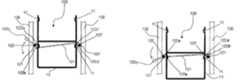
도 1은 본 발명에서 바람직한 실시예로 제공된 링크구조를 구비한 농업용 컨테이너박스 운반장치의 전체구조를 보여주는 사시도이다.1 is a perspective view showing the overall structure of the agricultural container box transport apparatus having a link structure provided as a preferred embodiment in the present invention.
본 실시예에 따른 농업용 컨테이너박스 운반장치(100)는, 도 1 에서 보는 바와 같이 운반장치(100)를 전체적으로 이송가능하도록 하는 이송구조체(110)와 상기 이송구조체(110)의 상부에 승강 및 협지를 위한 수단이 설치된 형태로 구성되며, 구체적으로는 상기 승강 및 협지를 위한 수단은 하나 이상 적층된 컨테이너박스를 협지하여 승강시킬 수 있도록 된 승강암부(120)와, 상기 승강암부(120)의 승강경로인 승강레일(130) 및 상기 승강암부(120)에 승강력을 제공하는 동력수단을 포함하여 구성된다.Agricultural container
도 1에서 보는 바와 같이, 상기 이송구조체(110)는 금속제 프레임구조체의 하부 4개의 각 모서리부분에 이송롤러(111)가 설치되어 원활한 이송이 가능하도록 이루어지며, 이 이송구조체(110)의 상부에는 수직방향으로 한 쌍의 승강레일(130)이 평행하게 이격 설치되어 있다.As shown in Figure 1, the
한편, 도면에서는 이송구조체(110)에 4개의 이송롤러(111)를 설치한 상태를 보여주지만, 앞쪽에는 이송롤러 대신에 지지발(도시하지 않음)을 설치하고 이송시에는 앞쪽을 약간 들어 뒤쪽의 이송롤러만으로 이송시키는 형태도 가능하며, 상기 승강레일(130) 또한 도면에서와 같이 한 쌍으로 설치하지 않고, 중앙부에 승강레일(130)을 하나만 설치하고 여기에 한 쌍의 암축을 연결하는 것도 가능하며, 이러한 형태의 단순한 형상의 변경은 모두 본 발명의 실시범위에 속하는 것으로 이해한다.On the other hand, the drawing shows a state in which four
그리고 상기 승강레일(130)을 따라 승강되는 승강암부(120)는, 한 쌍의 암축(121, 121')이 상호 평행한 구조로 이격 설치되어 있다. 여기서 이 암축들(121, 12')간의 이격폭은, 이 이격공간(S)상에 위치되는 컨테이너박스의 폭 또는 길이에 준하게 된다.In addition, the lifting
그리고 상기 승강암부(120)에 승강에 요구되는 작용력을 제공하는 동력수단은, 유압실린더(도시하지 않음)를 승강암부(120)에 결속시켜 이 유압실린더의 인장 및 수축작용에 의해 승강암부(120)가 승강되도록 하는 형태와, 승강레일에 정역모터에 의해 이송되는 승강체인을 마련하고, 이 승강체인에 승강암부의 양편을 치합시켜 승강체인의 이송작용으로 승강암부가 승강되도록 하는 형태, 및 승강암부에 정역모터에 의해 권취되는 와이어(도시하지 않음)를 결속시켜, 이 와이어의 견인작용으로 승강암부가 승강되도록 하는 형태의 동력수단 등 공지의 기술들 중에서 선 택될 수 있다.And the power means for providing the lifting force to the
다만, 본 실시예에서는 작동의 안정성 및 외관을 고려하여, 도 1에서 보는 바와 같이 승강레일(130)에 정역모터(140)에 의해 이송되는 승강체인(141)을 마련하고, 이 승강체인(141)에 승강암부(120)의 양편을 결속시켜 승강체인(141)의 이송작용으로 승강암부(120)가 승강되도록 한 동력수단을 채택하고 있다.However, in the present embodiment, in consideration of the stability and appearance of the operation, as shown in FIG. 1 provides a
한편, 이하에서는 본 발명에 따른 농업용 컨테이너박스 운반장치(100)에 있어서의 컨테이너박스를 협지 또는 협지 해제하기 위한 승강암부(120)의 구조의 바람직한 형태를 도 2 내지 도 3을 참조하여 상세하게 설명한다.On the other hand, in the following description of the preferred form of the structure of the
도 2a는 본 발명에서 제 1 실시형태로 제공된 링크구조를 보여주는 것이고, 도 2b는 상기 도 2a에 도시된 링크구조의 작용상태를 보여주는 것이며, 도 3a는 본 발명에서 제 2 실시형태로 제공된 링크구조를 보여주는 것으로, 도 3b는 상기 도 3a에 도시된 링크구조의 작용상태를 보여주는 것이다. FIG. 2A shows the link structure provided in the first embodiment in the present invention, FIG. 2B shows the working state of the link structure shown in FIG. 2A, and FIG. 3A shows the link structure provided in the second embodiment in the present invention. 3b shows an operational state of the link structure shown in FIG. 3a.
본 발명에서는 상기와 같이 승강암부(120)가 컨테이너박스를 협지할 수 있도록, 도 1 내지 도 3에서 보는 바와 같이 상기 승강암부(120)의 암축(121, 121')에 협지부재(122, 122')를 상호 대향하도록 축 설치하고, 이들 협지부재들(122, 122')을 링크구조(150, 160)로 연결하여, 이들 한 쌍의 협지부재(122, 122')들에 의해 컨테이너박스(10)가 협지될 수 있도록 하고 있다.In the present invention, as shown in FIGS. 1 to 3, the clamping
좀 더 상세하게는, 상기 협지부재(122, 122')는, 협지시 컨테이너박스에 결착되는 결착돌기(122a, 122a')와 상기 링크구조(150, 160)에 결속되는 연결돌기(122b, 122b')가 소정각도를 이루며 형성되고, 한 쌍의 협지부재(122, 122')에 있어서 상기 결착돌기(122a, 122a')와 연결돌기(122b, 122b')의 상하위치는 도 2a 및 3a에서 보는 바와 같이 서로 반대가 되도록 설치되어, 상기 링크구조(150, 160)에 의해 상호 연동하여 제한적인 회동이 이루어지도록 연결된 것을 특징으로 하고 있다.More specifically, the gripping
따라서 상기 협지부재(122, 122')는, 컨테이너박스(10)에서 요입된 손잡이(11)부분에 결착돌기(122a, 122a')가 결착되어 협지하게 되며, 링크구조(150, 160)에 의해 연동되면서 소정각만이 제한적으로 회동되게 된다.Therefore, the holding
상기 링크구조에 대해 좀 더 살펴보면, 본 발명에서 제 1 실시형태로 제공되고 있는 링크구조(150)는, 도 2a에서 보는 바와 같이 상기 암축(121, 121')에 대향 설치된 한 쌍의 협지부재(122, 122')들이 수평에 대해 소정 각도 경사지게 설치된 하나의 링크부재(151)의 양단(151a, 151b)에 힌지(H)구조로 결속되어, 이 링크부재(151)에 의해 상기 한 쌍의 협지부재(122, 122')가 연동하여 회동되도록 구성되어 있다. 그리고, 상기 링크부재(151)와 연결된 협지부재들(122, 122') 중, 어느 하나에는 손잡이(122c)를 마련하여, 이 손잡이(122c)를 통해 협지부재(122, 122')를 손쉽게 조작하여 회동시킬 수 있도록 하고 있다.Looking at the link structure in more detail, the
이렇게 구성된 링크구조(150)에 의하면, 도 2b에서 보는 바와 같이 사용자가 손잡이(122c)를 정방향으로 회전시키게 되면, 손잡이에 연결된 협지부재(122)도 정방향으로 회전하면서 결착돌기(122a)가 내측으로, 연결돌기(122b)는 하측으로 이동하고, 이에 연결된 링크부재(151)의 일단(151a)은 하측으로 회동하면서 그 타단 (151b)에 연결된 협지부재(122')의 연결돌기(122b')는 상측으로, 결착돌기(122a')는 내측으로 회동되고, 따라서 컨테이너박스(100)의 손잡이(110)는 협지부재(122, 122')에 의해 협지되게 된다.According to the
그리고 사용자가 손잡이(122c)를 역방향으로 회전시키게 되면, 암축(121, 121')에 대칭되게 설치된 협지부재(122, 122')들은 상기 설명한 것과 반대로 회동되고, 따라서 컨테이너박스(100)의 협지상태는 해제되게 된다.When the user rotates the
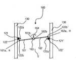
한편, 본 발명에서 제 2형태로 제공되고 있는 링크구조(160)는, 도 3a에서 보는 바와 같이, 소정 직경을 갖는 원형의 연결몸체(163)를 중심으로, 상기 연결몸체(163)의 양측에 2개의 링크부재(161, 162)의 일단(161b, 162b)이 각각 힌지구조로 결속되며, 상기 링크부재들(161, 162)의 타단(161a, 162a)은 상기 협지부재(122, 122')의 연결돌기(122b, 122b')와 각각 힌지구조(H)로 결속되어 있다.On the other hand, the
그리고 본 실시예에서는 상기 제 2 형태의 링크구조(160)를 구현함에 있어, 링크부재(161, 162)간을 연결하고 있는 연결부재(163)에 손잡이(164)를 마련하여, 이 손잡이(164)를 이용하여 외부에서 손쉽게 연결부재(163)를 회전시킬 수 있도록 하고 있다.In the present embodiment, in implementing the
이렇게 구성하게 되면, 암축(121, 121')에 마련된 한 쌍의 협지부재(122, 122')가 상호 연동하여 소정각 회동하게 되고, 따라서 암축(121, 121')간의 이격공간(S)에 위치된 컨테이너박스(10)는, 손잡이부(11)의 조작에 의해 협지 및 해제가 이루어지게 된다.In this configuration, the pair of clamping
따라서 이렇게 구성된 본 발명에 따른 농업용 컨테이너박스 운반장치(100)를 이용하여 컨테이너박스를 운반할 경우, 먼저 사용자는 승강암부(120)를 이용하여 컨테이너박스의 측면을 협지하여 일정높이로 상승시키고, 승강레일(130)에 부설된 손잡이(170)를 잡아 본 장치(100)를 밀어 원하는 위치로 이동시킨 다음, 승강암부(120)를 하강시켜 컨테이너박스를 땅 위에 내려놓은 뒤, 협지상태를 해제시켜, 컨테이너박스의 운반을 완료하게 된다.Therefore, when transporting the container box using the agricultural container
전술한 바와 같이 본 발명에 따른 농업용 컨테이너박스 운반장치는, 하나이상 적층된 상태 농업용 컨테이너박스를 손쉽게 협지하여 운반할 수 있다.As described above, the agricultural container box transport apparatus according to the present invention can be carried by easily sandwiching one or more stacked agricultural container boxes.
또한 본 실시예에서 제공된 링크구조를 통한 컨테이너박스의 협지형태는 구조가 간편하고 또 안정적이며, 사용이 간편한 이점을 가진다.In addition, the clamping form of the container box through the link structure provided in the present embodiment has the advantage that the structure is simple, stable, and easy to use.
특히 본 발명이 실제 제품화되게 되면, 종래 인력에 의존하고 있는 컨테이너박스의 적재 및 하역과정이, 기계화될 수 있어 그 편리성이 증대된다 할 것이다.In particular, when the present invention is actually manufactured, the loading and unloading process of the container box, which is dependent on the conventional manpower, may be mechanized, thereby increasing convenience.
Claims (5)
Translated fromKoreanPriority Applications (1)
| Application Number | Priority Date | Filing Date | Title |
|---|---|---|---|
| KR1020040070689AKR100606855B1 (en) | 2004-09-06 | 2004-09-06 | Container Container Carrier |
Applications Claiming Priority (1)
| Application Number | Priority Date | Filing Date | Title |
|---|---|---|---|
| KR1020040070689AKR100606855B1 (en) | 2004-09-06 | 2004-09-06 | Container Container Carrier |
Publications (2)
| Publication Number | Publication Date |
|---|---|
| KR20060021961A KR20060021961A (en) | 2006-03-09 |
| KR100606855B1true KR100606855B1 (en) | 2006-08-01 |
Family
ID=37128614
Family Applications (1)
| Application Number | Title | Priority Date | Filing Date |
|---|---|---|---|
| KR1020040070689AExpired - Fee RelatedKR100606855B1 (en) | 2004-09-06 | 2004-09-06 | Container Container Carrier |
Country Status (1)
| Country | Link |
|---|---|
| KR (1) | KR100606855B1 (en) |
Cited By (3)
| Publication number | Priority date | Publication date | Assignee | Title |
|---|---|---|---|---|
| KR20210130933A (en) | 2020-04-23 | 2021-11-02 | 강동길 | Cart for carrying box have a lift divice |
| KR20230081525A (en) | 2021-11-30 | 2023-06-07 | 강동길 | Cart for carrying box have a lift divice |
| KR20240100907A (en) | 2022-12-23 | 2024-07-02 | 강동길 | Divice for fixing of a carrying box |
Families Citing this family (2)
| Publication number | Priority date | Publication date | Assignee | Title |
|---|---|---|---|---|
| CN106976664B (en)* | 2017-04-14 | 2019-04-12 | 广西高农机械有限公司 | It is a kind of for agricultural crop storage and the device of transport |
| CN111846705A (en)* | 2020-07-03 | 2020-10-30 | 刘治清 | Medical garbage bin carrier |
Citations (4)
| Publication number | Priority date | Publication date | Assignee | Title |
|---|---|---|---|---|
| JPH06144769A (en)* | 1992-11-10 | 1994-05-24 | Toyokuni Densen Kk | Bobbin hoisting fixture |
| JPH08318860A (en)* | 1995-05-24 | 1996-12-03 | Okudaya Giken:Kk | Box cart |
| JP2003246599A (en)* | 2002-02-21 | 2003-09-02 | Sugiyasu Industries Co Ltd | Leveler |
| JP2004189000A (en) | 2002-12-06 | 2004-07-08 | Yec Co Ltd | Carrier for cargo conveyance |
- 2004
- 2004-09-06KRKR1020040070689Apatent/KR100606855B1/ennot_activeExpired - Fee Related
Patent Citations (4)
| Publication number | Priority date | Publication date | Assignee | Title |
|---|---|---|---|---|
| JPH06144769A (en)* | 1992-11-10 | 1994-05-24 | Toyokuni Densen Kk | Bobbin hoisting fixture |
| JPH08318860A (en)* | 1995-05-24 | 1996-12-03 | Okudaya Giken:Kk | Box cart |
| JP2003246599A (en)* | 2002-02-21 | 2003-09-02 | Sugiyasu Industries Co Ltd | Leveler |
| JP2004189000A (en) | 2002-12-06 | 2004-07-08 | Yec Co Ltd | Carrier for cargo conveyance |
Non-Patent Citations (1)
| Title |
|---|
| 15246599 * |
Cited By (3)
| Publication number | Priority date | Publication date | Assignee | Title |
|---|---|---|---|---|
| KR20210130933A (en) | 2020-04-23 | 2021-11-02 | 강동길 | Cart for carrying box have a lift divice |
| KR20230081525A (en) | 2021-11-30 | 2023-06-07 | 강동길 | Cart for carrying box have a lift divice |
| KR20240100907A (en) | 2022-12-23 | 2024-07-02 | 강동길 | Divice for fixing of a carrying box |
Also Published As
| Publication number | Publication date |
|---|---|
| KR20060021961A (en) | 2006-03-09 |
Similar Documents
| Publication | Publication Date | Title |
|---|---|---|
| EP0425167A1 (en) | Load handling apparatus | |
| US5118243A (en) | Pallet load transfer method and apparatus | |
| JPH0696440B2 (en) | Slip sheet processing equipment | |
| KR101787036B1 (en) | truck for transferring palette | |
| CN105692507A (en) | Material circulation box automatic turnover device based on forklift transportation | |
| KR100606855B1 (en) | Container Container Carrier | |
| JP3340843B2 (en) | Transfer container assembling method and apparatus | |
| CN112477944B (en) | Material carrying trolley for building | |
| US5102282A (en) | Unit load transfer device and method | |
| JP2012001300A (en) | Attachment for forklift and freight handling method using the same | |
| CA1080159A (en) | Bundle carrier attachment for fork lift trucks | |
| EP3081453A1 (en) | Roll container and method of transporting a plurality of roll containers | |
| CN208615966U (en) | Lifting carrier | |
| KR101793506B1 (en) | Clamping apparatus for fork lift | |
| CN117302891A (en) | Remove the dragging device | |
| US11235932B1 (en) | Modular roller conveyor | |
| CN205575509U (en) | Automatic turning device of material cycling case based on forklift transportation | |
| JP3903796B2 (en) | Article transfer device | |
| US6619905B2 (en) | Drum handling device | |
| KR20170003307U (en) | Transport carts | |
| EP1460027A1 (en) | Multifunctional trolley with high mobility | |
| JP2009067186A (en) | Cart having cargo lifting mechanism | |
| CN222555227U (en) | A cast pipe packaging vehicle | |
| JPS5916356Y2 (en) | Article stacking device | |
| JP3816167B2 (en) | Continuous transfer device |
Legal Events
| Date | Code | Title | Description |
|---|---|---|---|
| A201 | Request for examination | ||
| PA0109 | Patent application | St.27 status event code:A-0-1-A10-A12-nap-PA0109 | |
| PA0201 | Request for examination | St.27 status event code:A-1-2-D10-D11-exm-PA0201 | |
| D13-X000 | Search requested | St.27 status event code:A-1-2-D10-D13-srh-X000 | |
| D14-X000 | Search report completed | St.27 status event code:A-1-2-D10-D14-srh-X000 | |
| E902 | Notification of reason for refusal | ||
| PE0902 | Notice of grounds for rejection | St.27 status event code:A-1-2-D10-D21-exm-PE0902 | |
| PG1501 | Laying open of application | St.27 status event code:A-1-1-Q10-Q12-nap-PG1501 | |
| E13-X000 | Pre-grant limitation requested | St.27 status event code:A-2-3-E10-E13-lim-X000 | |
| P11-X000 | Amendment of application requested | St.27 status event code:A-2-2-P10-P11-nap-X000 | |
| P13-X000 | Application amended | St.27 status event code:A-2-2-P10-P13-nap-X000 | |
| E701 | Decision to grant or registration of patent right | ||
| PE0701 | Decision of registration | St.27 status event code:A-1-2-D10-D22-exm-PE0701 | |
| GRNT | Written decision to grant | ||
| PR0701 | Registration of establishment | St.27 status event code:A-2-4-F10-F11-exm-PR0701 | |
| PR1002 | Payment of registration fee | St.27 status event code:A-2-2-U10-U11-oth-PR1002 Fee payment year number:1 | |
| PG1601 | Publication of registration | St.27 status event code:A-4-4-Q10-Q13-nap-PG1601 | |
| PR1001 | Payment of annual fee | St.27 status event code:A-4-4-U10-U11-oth-PR1001 Fee payment year number:4 | |
| PR1001 | Payment of annual fee | St.27 status event code:A-4-4-U10-U11-oth-PR1001 Fee payment year number:5 | |
| PR1001 | Payment of annual fee | St.27 status event code:A-4-4-U10-U11-oth-PR1001 Fee payment year number:6 | |
| FPAY | Annual fee payment | Payment date:20121016 Year of fee payment:7 | |
| PR1001 | Payment of annual fee | St.27 status event code:A-4-4-U10-U11-oth-PR1001 Fee payment year number:7 | |
| FPAY | Annual fee payment | Payment date:20130528 Year of fee payment:8 | |
| PR1001 | Payment of annual fee | St.27 status event code:A-4-4-U10-U11-oth-PR1001 Fee payment year number:8 | |
| PR1001 | Payment of annual fee | St.27 status event code:A-4-4-U10-U11-oth-PR1001 Fee payment year number:9 | |
| R18-X000 | Changes to party contact information recorded | St.27 status event code:A-5-5-R10-R18-oth-X000 | |
| FPAY | Annual fee payment | Payment date:20150616 Year of fee payment:10 | |
| PR1001 | Payment of annual fee | St.27 status event code:A-4-4-U10-U11-oth-PR1001 Fee payment year number:10 | |
| FPAY | Annual fee payment | Payment date:20160524 Year of fee payment:11 | |
| PR1001 | Payment of annual fee | St.27 status event code:A-4-4-U10-U11-oth-PR1001 Fee payment year number:11 | |
| P22-X000 | Classification modified | St.27 status event code:A-4-4-P10-P22-nap-X000 | |
| FPAY | Annual fee payment | Payment date:20170529 Year of fee payment:12 | |
| PR1001 | Payment of annual fee | St.27 status event code:A-4-4-U10-U11-oth-PR1001 Fee payment year number:12 | |
| FPAY | Annual fee payment | Payment date:20180625 Year of fee payment:13 | |
| PR1001 | Payment of annual fee | St.27 status event code:A-4-4-U10-U11-oth-PR1001 Fee payment year number:13 | |
| R18-X000 | Changes to party contact information recorded | St.27 status event code:A-5-5-R10-R18-oth-X000 | |
| FPAY | Annual fee payment | Payment date:20190613 Year of fee payment:14 | |
| PR1001 | Payment of annual fee | St.27 status event code:A-4-4-U10-U11-oth-PR1001 Fee payment year number:14 | |
| PC1903 | Unpaid annual fee | St.27 status event code:A-4-4-U10-U13-oth-PC1903 Not in force date:20200725 Payment event data comment text:Termination Category : DEFAULT_OF_REGISTRATION_FEE | |
| PC1903 | Unpaid annual fee | St.27 status event code:N-4-6-H10-H13-oth-PC1903 Ip right cessation event data comment text:Termination Category : DEFAULT_OF_REGISTRATION_FEE Not in force date:20200725 | |
| R18-X000 | Changes to party contact information recorded | St.27 status event code:A-5-5-R10-R18-oth-X000 |