KR100606165B1 - Multiple diaphragm for microphone and condenser microphone using same - Google Patents
Multiple diaphragm for microphone and condenser microphone using sameDownload PDFInfo
- Publication number
- KR100606165B1 KR100606165B1KR1020040026632AKR20040026632AKR100606165B1KR 100606165 B1KR100606165 B1KR 100606165B1KR 1020040026632 AKR1020040026632 AKR 1020040026632AKR 20040026632 AKR20040026632 AKR 20040026632AKR 100606165 B1KR100606165 B1KR 100606165B1
- Authority
- KR
- South Korea
- Prior art keywords
- ring
- back plate
- diaphragm
- case
- vibration
- Prior art date
- Legal status (The legal status is an assumption and is not a legal conclusion. Google has not performed a legal analysis and makes no representation as to the accuracy of the status listed.)
- Expired - Fee Related
Links
Images


Classifications
- H—ELECTRICITY
- H04—ELECTRIC COMMUNICATION TECHNIQUE
- H04R—LOUDSPEAKERS, MICROPHONES, GRAMOPHONE PICK-UPS OR LIKE ACOUSTIC ELECTROMECHANICAL TRANSDUCERS; DEAF-AID SETS; PUBLIC ADDRESS SYSTEMS
- H04R7/00—Diaphragms for electromechanical transducers; Cones
- H04R7/02—Diaphragms for electromechanical transducers; Cones characterised by the construction
- H04R7/04—Plane diaphragms
- H04R7/06—Plane diaphragms comprising a plurality of sections or layers
- H—ELECTRICITY
- H04—ELECTRIC COMMUNICATION TECHNIQUE
- H04R—LOUDSPEAKERS, MICROPHONES, GRAMOPHONE PICK-UPS OR LIKE ACOUSTIC ELECTROMECHANICAL TRANSDUCERS; DEAF-AID SETS; PUBLIC ADDRESS SYSTEMS
- H04R1/00—Details of transducers, loudspeakers or microphones
- H04R1/02—Casings; Cabinets ; Supports therefor; Mountings therein
- H—ELECTRICITY
- H04—ELECTRIC COMMUNICATION TECHNIQUE
- H04R—LOUDSPEAKERS, MICROPHONES, GRAMOPHONE PICK-UPS OR LIKE ACOUSTIC ELECTROMECHANICAL TRANSDUCERS; DEAF-AID SETS; PUBLIC ADDRESS SYSTEMS
- H04R2231/00—Details of apparatus or processes specially adapted for the manufacture of transducers or diaphragms therefor covered by H04R31/00, not provided for in its subgroups
- H04R2231/003—Manufacturing aspects of the outer suspension of loudspeaker or microphone diaphragms or of their connecting aspects to said diaphragms
Landscapes
- Engineering & Computer Science (AREA)
- Physics & Mathematics (AREA)
- Acoustics & Sound (AREA)
- Signal Processing (AREA)
- Multimedia (AREA)
- Electrostatic, Electromagnetic, Magneto- Strictive, And Variable-Resistance Transducers (AREA)
Abstract
Translated fromKoreanDescription
Translated fromKorean도 1은 종래의 마이크로폰용 진동판의 구조를 도시한 도면,1 is a view showing the structure of a conventional diaphragm for a microphone,
도 2a 내지 2c는 본 발명에 따른 마이크로폰용 다중 진동판을 도시한 도면,2a to 2c are views showing the multiple diaphragm for the microphone according to the present invention,
도 3은 본 발명이 적용된 콘덴서 마이크로폰의 제1 실시예,3 is a first embodiment of a condenser microphone to which the present invention is applied;
도 4는 본 발명이 적용된 콘덴서 마이크로폰의 제2 실시예,4 is a second embodiment of a condenser microphone to which the present invention is applied;
도 5는 본 발명이 적용된 콘덴서 마이크로폰의 제3 실시예.5 is a third embodiment of a condenser microphone to which the present invention is applied.
*도면의 주요부분에 대한 부호의 설명* Explanation of symbols for main parts of the drawings
100: 다중 진동판110: 극판100: multiple diaphragm 110: pole plate
120: 진동막112: 진동홀120: vibration membrane 112: vibration hole
202: 케이스204: 진동판202: case 204: diaphragm
206: 스페이서208: 절연링206: spacer 208: insulating ring
210: 백플레이트212: 도전링210: back plate 212: conductive ring
214: PCB214: PCB
본 발명은 콘덴서 마이크로폰에 관한 것으로, 더욱 상세하게는 마이크로폰의 다중 진동판 및 이를 이용한 콘덴서 마이크로폰에 관한 것이다.The present invention relates to a condenser microphone, and more particularly, to a condenser microphone using multiple diaphragms of the microphone and the same.
일반적으로, 이동통신 단말기나 오디오 등에 널리 사용되는 콘덴서 마이크로폰은 전압 바이어스 요소와, 음압(sound pressure)에 대응하여 변화하는 커패시터(C)를 형성하는 다이어프램/백플레이트 쌍, 그리고 출력신호를 버퍼링하기 위한 전계 효과 트랜지스터(JFET)로 이루어진다.In general, a condenser microphone widely used in a mobile communication terminal or an audio device includes a voltage bias element, a diaphragm / backplate pair forming a capacitor C that changes in response to sound pressure, and a buffer for output signal. It consists of a field effect transistor (JFET).
이러한 콘덴서 마이크로폰은 하나의 케이스 안에 진동판과, 스페이서링, 절연링, 백플레이트, 통전링, PCB가 일체로 조립된 조립체로 이루어지는데, 종래의 진동판(10)은 도 1에 도시된 바와 같이 금속으로 된 원통형의 극링(12)에 금속막이 코팅되어 있는 폴리에틸렌 테레프탈레이트(PET), PPS(Polyphenylene Sulfide) 등의 폴리머 필름으로 된 진동막(14)을 부착한 구조로 되어 있다.The condenser microphone is composed of an assembly in which a diaphragm, a spacer ring, an insulating ring, a back plate, an energizing ring, and a PCB are integrally assembled in one case. The
이러한 종래의 진동판(10)은 하나의 진동홀(12a)을 통해 진동막(14)이 진동하기 때문에 집음효과가 미흡한 문제점이 있다.The
본 발명은 상기와 같은 문제점을 해결하기 위하여 금속판에 진동홀을 다수 형성하여 집음효과가 일어나도록 된 다중 진동판 및 이를 이용한 콘덴서 마이크로 폰을 제공하는데 그 목적이 있다.
An object of the present invention is to provide a multi-vibration plate and a condenser microphone using the same to form a sound collecting effect by forming a plurality of vibration holes in the metal plate to solve the above problems.
상기와 같은 목적을 달성하기 위하여 본 발명의 진동판은, 콘덴서 마이크로폰에 있어서, 적어도 2개 이상의 진동홀이 형성된 금속판으로 된 극링; 상기 극링에 부착되는 진동막으로 구성된 것을 특징으로 한다. 여기서, 상기 진동막은 금속막이 코팅되어 있는 PET, PPS 등의 폴리머 필름으로 이루어진다.In order to achieve the above object, the diaphragm of the present invention comprises: a condenser microphone comprising: a pole ring made of a metal plate having at least two vibration holes; It is characterized by consisting of a vibration membrane attached to the pole ring. Here, the vibrating membrane is made of a polymer film, such as PET, PPS is coated with a metal film.
또한 상기와 같은 목적을 달성하기 위하여 본 발명의 마이크로폰은, 바닥면에 전방음향을 유입하기 위한 음향홀이 형성되고 타면이 개구된 통형으로 되어 개구면이 커링된 케이스; 적어도 2개 이상의 진동홀이 형성된 금속판으로 된 극링과, 상기 극링에 부착되는 진동막으로 구성된 다중 진동판; 상기 진동판에 접촉되는 스페이서; 상기 케이스에 삽입되어 절연기능을 제공하기 위한 절연링; 상기 절연링 안에서 상기 스페이서를 사이에 두고 상기 진동판과 대향하도록 삽입된 백 플레이트; 상기 절연링 내에 위치하고 상기 백 플레이트를 지지하며, 상기 백 플레이트에 전기적인 접속을 제공하기 위한 도전링; 및 상기 도전링을 통해 상기 백플레이트와 전기적으로 연결되고, 상기 케이스를 통해 상기 진동막과 전기적으로 연결되며, 회로소자가 설치된 PCB를 구비한 것을 특징으로 한다.In addition, the microphone of the present invention in order to achieve the above object, the sound hole for introducing the front sound in the bottom surface is formed and the other surface is opened in the tubular opening is cured; A multiple diaphragm comprising a pole ring made of a metal plate having at least two vibration holes and a vibration membrane attached to the pole ring; A spacer in contact with the diaphragm; An insulation ring inserted into the case to provide an insulation function; A back plate inserted into the insulating ring to face the diaphragm with the spacer interposed therebetween; A conductive ring located within the insulating ring and supporting the back plate, the conductive ring providing electrical connection to the back plate; And a PCB electrically connected to the back plate through the conductive ring, electrically connected to the vibrating membrane through the case, and provided with a circuit element.
이하, 첨부된 도면을 참조하여 본 발명의 바람직한 실시예를 자세히 설명하기로 한다.Hereinafter, exemplary embodiments of the present invention will be described in detail with reference to the accompanying drawings.
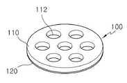
도 2a는 본 발명에 따른 마이크로폰용 다중 진동판을 도시한 사시도이고, 도 2b는 평면도이며, 도 2c는 측단면도이다.Figure 2a is a perspective view showing a multiple diaphragm for a microphone according to the present invention, Figure 2b is a plan view, Figure 2c is a side cross-sectional view.
도 2a 내지 도 2c를 참조하면, 본 발명의 다중 진동판(100)은 적어도 2개 이상의 진동홀(112)이 형성된 금속판으로 된 극링(110)과, 극링(110)에 부착되는 진동막(120)으로 구성된다. 진동막(120)은 금속막이 코팅되어 있는 폴리에틸렌 테레프탈레이트(PET), PPS(Polyphenylene Sulfide) 등의 폴리머 필름으로 이루어진다.2A to 2C, the
이러한 진동판(100)은 스페이서를 사이에 두고 백플레이트와 대향하여 다수의 진동셀을 형성하게 되는데, 각 진동셀은 전방 음향홀을 통해 유입된 음압에 의해 각각 독립적으로 진동하여 전체적으로 집음효과를 달성한다.The
도 3은 본 발명이 적용된 콘덴서 마이크로폰의 제1 실시예로서, 본 발명의 다중 진동판을 통상의 원형 마이크로폰에 적용한 경우이다.3 is a first embodiment of the condenser microphone to which the present invention is applied, and is a case where the multiple diaphragm of the present invention is applied to a conventional circular microphone.
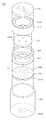
도 3을 참조하면, 본 발명 제1 실시예의 마이크로폰(200)은 일면이 개구되고 바닥면에 음향홀(202a)이 형성된 원통형의 케이스(202)와, 원통형의 케이스(202)에 삽입되는 다중 진동판(204), 링형의 얇은 스페이서(206), 상하가 개구된 원통형의 절연링(208), 음공(210a)이 형성된 원판형의 백플레이트(210), 백플레이트(210)를 회로기판(PCB:214)과 전기적으로 접속시키기 위한 도전링(212), 일면에 부품(IC, MLCC)이 실장되고 타면에 접속단자가 형성된 원판형의 PCB(214)로 구성되어 있다. 여기서, 다중 진동판(204)은 다수의 진동홀(112)이 형성된 금속판으로 된 극링(204b)과, 극링(204b)에 부착되는 진동막(204a)으로 구성되고, 진동막(204a)은 금속막이 코팅되어 있는 PET, PPS 등의 폴리머 필름으로 이루어진 다. 백플레이트(210)는 금속판에 유기필름이 융착되어 있고 유기필름에 일렉트릿이 형성되어 있다.Referring to FIG. 3, the
이와 같은 제1 실시예의 콘덴서 마이크로폰(200)은 원통형 모양의 케이스(202)안에 다중 진동판(204), 스페이서(206), 절연링(208), 음공(210a)이 형성된 백플레이트(210), 도전링(212), 원판형의 PCB(214)가 순차적으로 배설된 후 케이스(202)의 끝단을 커링시킨 구조로 조립되어 있다.The
이와 같은 제1 실시예의 콘덴서 마이크로폰의 동작을 살펴보면 다음과 같다.The operation of the condenser microphone of the first embodiment is as follows.
본 발명에 따른 콘덴서 마이크로폰(200)은 접속단자를 통해 외부로부터 Vdd와 GND 전원이 인가된다. 이에 따라 본 발명에 따른 콘덴서 마이크로폰의 다중 진동판(204)은 케이스(202)를 거쳐 PCB(214)와 전기적으로 연결되고, 백플레이트(210)는 도전링(212)을 통해 PCB(214)와 전기적으로 연결된다.In the
이와 같은 상태에서 외부 음원으로부터의 음향은 케이스(202)의 음향홀(202a)을 통해 마이크로폰의 내부로 유입되어 극링(204b)의 각 진동홀(112)로 전달되어 진동막(204a)을 개별적으로 진동시키고, 각 진동홀(112)의 진동막(204a)이 진동함에 따라 각 진동홀의 진동막(204a)과 백플레이트(210)와의 간격이 변하게 되며, 그 결과 정전용량이 변화되어 음파에 따른 전기적인 신호(전압)의 변화를 얻을 수 있고, 이 신호가 앞서의 전기적인 연결선로를 따라 PCB(214)에 실장된 IC로 전달되어 증폭된 후 접속단자를 통해 외부 회로로 출력된다.In such a state, the sound from the external sound source is introduced into the microphone through the
도 4는 본 발명이 적용된 콘덴서 마이크로폰의 제2 실시예로서, 본 발명의 다중 진동판을 통합 베이스를 갖는 콘덴서 마이크로폰에 적용한 예이다.4 is a second embodiment of the condenser microphone to which the present invention is applied, and is an example of applying the multiple diaphragm of the present invention to a condenser microphone having an integrated base.
도 4를 참조하면, 본 발명에 따른 콘덴서 마이크로폰(300)은 일면이 개구된 원통형의 케이스(302)에 진동판(304), 스페이서(306), 백플레이트 절연링(308), 백플레이트(310), 통합 베이스(312), PCB(314)가 순차적으로 배설된 후 케이스(302)의 끝부분을 커링시켜 조립을 완료한다. 여기서, 다중 진동판(304)은 다수의 홀(112)이 형성된 금속판으로 된 극링(304b)과, 극링(304b)에 부착되는 진동막(304a)으로 구성되고, 진동막(304a)은 금속막이 코팅되어 있는 PET, PPS 등의 폴리머 필름으로 이루어진다.Referring to FIG. 4, the
이때 백플레이트(310)는 금속판에 유기필름(고분자필름)이 접착되어 구성되고, 유기필름(고분자필름)에는 일렉트릿이 형성되어 있으며, 통합 베이스(312)가 아닌 별도의 백플레이트 절연링(308)에 의해 케이스(302)와 절연되어 있다. 백플레이트(310)는 통합 베이스(312)에 의해 지지됨과 아울러 통합 베이스(312)의 양면 내측에 형성된 금속도금층으로 된 도전패턴(312a)에 의해 PCB 기판(314)에 전기적으로 접속된다. PCB기판(314)에는 JFET 등과 같은 회로부품이 실장되어 있고, 케이스(302)의 끝단이 커링되어 PCB(314)를 내측으로 압착하고 있다. 또한 백플레이트(310)와 통합 베이스(312) 및 PCB(314)에 의해 형성된 내부 공간을 백 챔버라 하는데, 본 발명에 따른 마이크로폰의 백 챔버는 종래의 제2 베이스가 없으므로 종래 마이크로폰의 백 챔버에 비해 체적을 크게 할 수 있다.In this case, the
이러한 본 발명의 콘덴서 마이크로폰(300)은 진동막(304a)이 극링(304b)과 케이스(302)를 통해 PCB(314)회로와 전기적으로 연결되고, 백플레이트(310)은 통합 베이스(312)의 도전패턴(312a)을 통해 PCB(314)회로와 전기적으로 연결되어 전기적인 회로를 구성하고 있다.In the
이와 같은 본 발명의 콘덴서 마이크로폰(300)은 외부의 음파에 의해 공기가 케이스(302)의 음향홀(302a)을 통해 마이크로폰 내부로 유입되면, 이 음압에 의해 각 진동홀의 진동막(304a)이 진동됨과 아울러 백플레이트(310)에 형성된 음공(310a)을 통해 PCB(314)와 백플레이트(310) 사이에 형성된 백 챔버로 유입된다. 이때, 음향홀(302a)을 통해 유입된 음압에 의해 진동막(304a)이 진동하게 되면, 진동막(304a)과 백플레이트(310)와의 간격이 변하게 된다. 그리고 음압에 의해 간격이 변하게 되면, 진동막(304a)과 백플레이트(310)에 의해 형성된 정전용량이 변화되어 음파에 따른 전기적인 신호(전압)의 변화를 얻을 수 있고, 이 신호가 PCB(314)에 실장된 JFET 등의 IC로 전달되어 증폭된 후 접속단자를 통해 외부로 전송된다.In the
도 5는 본 발명이 적용된 콘덴서 마이크로폰의 제3 실시예로서, 본 발명의 다중 진동판을 사각형 마이크로폰에 적용한 예이다. 본 발명의 제3 실시예에서는 내부의 소자도 사각형인 경우를 예로들어 설명하였으나 내부 소자의 형상이 원형인 경우에도 가능하다.5 is a third embodiment of the condenser microphone to which the present invention is applied, and is an example in which the multiple diaphragm of the present invention is applied to a rectangular microphone. In the third embodiment of the present invention, the case in which the inner element is also a quadrangle has been described as an example.
도 5를 참조하면, 본 발명의 콘덴서 마이크로폰(400)은, 일면이 개구되고 바닥면에 음을 유입하기 위한 음향홀(402a)이 형성된 사각통형의 케이스(402)와, 사각통형의 케이스(402)에 삽입될 수 있는 외주면이 사각형이고 다수의 원형 진동홀 이 형성된 진동판(404), 외주면이 사각형이고 내주면도 사각형으로 된 스페이서(406), 상하면이 개구된 사각통형의 절연링(408), 음공(410a)이 형성된 사각판형의 백플레이트(410), 백플레이트(410)를 회로기판(414)과 전기적으로 접속시키기 위한 외주면이 사각형이고 내주면도 사각형으로 된 도전링(412), 일면에 부품(IC, MLCC)이 실장되고 타면에 돌출단자가 형성된 사각판형의 PCB(414)로 구성되어 있다. 여기서, 진동판(404)은 다수의 진동홀(112)이 형성된 금속판으로 된 극링(404b)과, 극링(404b)에 부착되는 진동막(404a)으로 구성되고, 진동막(404a)은 금속막이 코팅되어 있는 PET, PPS 등의 폴리머 필름으로 이루어진다.Referring to FIG. 5, the
이와 같은 제3 실시예의 콘덴서 마이크로폰의 동작을 살펴보면 다음과 같다.The operation of the condenser microphone of the third embodiment is as follows.
본 발명에 따른 콘덴서 마이크로폰(400)은 메인 PCB의 접속단자에 접속되어 Vdd와 GND 전원이 인가된다. 이에 따라 본 발명에 따른 콘덴서 마이크로폰(400)에서 진동막(404a)은 케이스(402)와 극링(404b)을 거쳐 PCB(414)에 전기적으로 연결되고, 백플레이트(410)는 도전링(412)을 통해 PCB(414)와 전기적으로 연결된다.The
이와 같은 상태에서 외부 음원으로부터의 음향은 케이스의 음향홀(402a)을 통해 마이크로폰의 내부로 유입되어 진동막(404a)으로 전달되고, 백챔버의 음향은 백플레이트(410)의 음공(410a)을 지나 진동막(404a)으로 전달된다.In this state, the sound from the external sound source is introduced into the microphone through the
따라서 진동막(404a)은 음압에 의해 진동하게 되고, 이에 따라 진동막(404a)과 백플레이트(410)와의 간격이 변하게 되며, 그 결과 진동막(404a)과 백 플레이트(410)에 의해 형성된 정전용량이 변화되어 음파에 따른 전기적인 신호(전압)의 변화를 얻을 수 있고, 이 신호가 앞서의 전기적인 연결선로를 따라 PCB(414) 에 실장된 IC로 전달되어 증폭된 후 돌출단자를 통해 외부 회로로 출력된다.Therefore, the vibrating
이상에서 설명한 바와 같이, 본 발명에 따르면 극링에 다수의 진동홀을 형성하여 하나의 마이크로폰으로도 여러개의 마이크로폰을 사용하는 것과 같은 집음효과를 제공할 수 있다.
As described above, according to the present invention, a plurality of vibration holes may be formed in the pole ring to provide a sound collection effect such as using a plurality of microphones even with one microphone.
Claims (5)
Translated fromKoreanPriority Applications (1)
| Application Number | Priority Date | Filing Date | Title |
|---|---|---|---|
| KR1020040026632AKR100606165B1 (en) | 2004-04-19 | 2004-04-19 | Multiple diaphragm for microphone and condenser microphone using same |
Applications Claiming Priority (1)
| Application Number | Priority Date | Filing Date | Title |
|---|---|---|---|
| KR1020040026632AKR100606165B1 (en) | 2004-04-19 | 2004-04-19 | Multiple diaphragm for microphone and condenser microphone using same |
Publications (2)
| Publication Number | Publication Date |
|---|---|
| KR20050101419A KR20050101419A (en) | 2005-10-24 |
| KR100606165B1true KR100606165B1 (en) | 2006-08-01 |
Family
ID=37279884
Family Applications (1)
| Application Number | Title | Priority Date | Filing Date |
|---|---|---|---|
| KR1020040026632AExpired - Fee RelatedKR100606165B1 (en) | 2004-04-19 | 2004-04-19 | Multiple diaphragm for microphone and condenser microphone using same |
Country Status (1)
| Country | Link |
|---|---|
| KR (1) | KR100606165B1 (en) |
Families Citing this family (3)
| Publication number | Priority date | Publication date | Assignee | Title |
|---|---|---|---|---|
| KR100776192B1 (en)* | 2006-07-10 | 2007-11-16 | 주식회사 비에스이 | Diaphragm and Condenser Microphone |
| CN112492500A (en)* | 2020-11-27 | 2021-03-12 | 西人马联合测控(泉州)科技有限公司 | Differential capacitance microphone and manufacturing method thereof |
| CN115022785A (en)* | 2022-06-30 | 2022-09-06 | 深圳市奥多格科技有限公司 | A bone conduction microphone |
- 2004
- 2004-04-19KRKR1020040026632Apatent/KR100606165B1/ennot_activeExpired - Fee Related
Also Published As
| Publication number | Publication date |
|---|---|
| KR20050101419A (en) | 2005-10-24 |
Similar Documents
| Publication | Publication Date | Title |
|---|---|---|
| KR200330089Y1 (en) | Integrated base and electret condenser microphone using the same | |
| FI105880B (en) | Fastening of a micromechanical microphone | |
| KR100544283B1 (en) | A parallelepiped type condenser microphone for SMD | |
| KR100544282B1 (en) | Parallelepiped condenser microphone | |
| WO2009005211A1 (en) | Diaphragm with air groove and condenser microphone using the same | |
| KR20090039376A (en) | Parasitic capacitance condenser microphone assembly | |
| TW200814831A (en) | Electret condenser microphone | |
| KR100606165B1 (en) | Multiple diaphragm for microphone and condenser microphone using same | |
| KR100549188B1 (en) | Integrated bass and electret condenser microphone | |
| KR100464700B1 (en) | Electret condenser microphone | |
| KR100526022B1 (en) | Condenser microphone | |
| KR100675024B1 (en) | Conductive microphone of condenser microphone and condenser microphone using same | |
| KR100812688B1 (en) | Condenser Microphone | |
| KR100812690B1 (en) | Condenser microphone | |
| KR20090119268A (en) | Silicon condenser microphone and method of manufacturing silicon chip used therein | |
| KR20050087578A (en) | A parallelepiped type directional condenser microphone for smd | |
| KR20000019963U (en) | Condenser microphone for mobile comunication terminal | |
| KR100675511B1 (en) | Ring Backplate and Condenser Microphone Using the Same | |
| KR100499356B1 (en) | Directivity condenser microphone | |
| KR100537435B1 (en) | Directional condenser microphone | |
| KR100629688B1 (en) | Front sound unidirectional microphone | |
| JP2001145196A (en) | Front electret type condenser microphone | |
| KR20050025840A (en) | Condenser microphone | |
| JP2005086831A (en) | Variable capacitance microphone using space efficiently and having no characteristic variations | |
| KR100540137B1 (en) | Directional microphone |
Legal Events
| Date | Code | Title | Description |
|---|---|---|---|
| A201 | Request for examination | ||
| PA0109 | Patent application | St.27 status event code:A-0-1-A10-A12-nap-PA0109 | |
| PA0201 | Request for examination | St.27 status event code:A-1-2-D10-D11-exm-PA0201 | |
| R18-X000 | Changes to party contact information recorded | St.27 status event code:A-3-3-R10-R18-oth-X000 | |
| D13-X000 | Search requested | St.27 status event code:A-1-2-D10-D13-srh-X000 | |
| PG1501 | Laying open of application | St.27 status event code:A-1-1-Q10-Q12-nap-PG1501 | |
| D14-X000 | Search report completed | St.27 status event code:A-1-2-D10-D14-srh-X000 | |
| E902 | Notification of reason for refusal | ||
| PE0902 | Notice of grounds for rejection | St.27 status event code:A-1-2-D10-D21-exm-PE0902 | |
| E13-X000 | Pre-grant limitation requested | St.27 status event code:A-2-3-E10-E13-lim-X000 | |
| P11-X000 | Amendment of application requested | St.27 status event code:A-2-2-P10-P11-nap-X000 | |
| P13-X000 | Application amended | St.27 status event code:A-2-2-P10-P13-nap-X000 | |
| E701 | Decision to grant or registration of patent right | ||
| PE0701 | Decision of registration | St.27 status event code:A-1-2-D10-D22-exm-PE0701 | |
| GRNT | Written decision to grant | ||
| PR0701 | Registration of establishment | St.27 status event code:A-2-4-F10-F11-exm-PR0701 | |
| PR1002 | Payment of registration fee | St.27 status event code:A-2-2-U10-U11-oth-PR1002 Fee payment year number:1 | |
| PG1601 | Publication of registration | St.27 status event code:A-4-4-Q10-Q13-nap-PG1601 | |
| R18-X000 | Changes to party contact information recorded | St.27 status event code:A-5-5-R10-R18-oth-X000 | |
| PR1001 | Payment of annual fee | St.27 status event code:A-4-4-U10-U11-oth-PR1001 Fee payment year number:4 | |
| PR1001 | Payment of annual fee | St.27 status event code:A-4-4-U10-U11-oth-PR1001 Fee payment year number:5 | |
| PR1001 | Payment of annual fee | St.27 status event code:A-4-4-U10-U11-oth-PR1001 Fee payment year number:6 | |
| FPAY | Annual fee payment | Payment date:20120629 Year of fee payment:7 | |
| PR1001 | Payment of annual fee | St.27 status event code:A-4-4-U10-U11-oth-PR1001 Fee payment year number:7 | |
| FPAY | Annual fee payment | Payment date:20130715 Year of fee payment:8 | |
| PR1001 | Payment of annual fee | St.27 status event code:A-4-4-U10-U11-oth-PR1001 Fee payment year number:8 | |
| FPAY | Annual fee payment | Payment date:20140808 Year of fee payment:9 | |
| PR1001 | Payment of annual fee | St.27 status event code:A-4-4-U10-U11-oth-PR1001 Fee payment year number:9 | |
| LAPS | Lapse due to unpaid annual fee | ||
| PC1903 | Unpaid annual fee | St.27 status event code:A-4-4-U10-U13-oth-PC1903 Not in force date:20150722 Payment event data comment text:Termination Category : DEFAULT_OF_REGISTRATION_FEE | |
| P22-X000 | Classification modified | St.27 status event code:A-4-4-P10-P22-nap-X000 | |
| PC1903 | Unpaid annual fee | St.27 status event code:N-4-6-H10-H13-oth-PC1903 Ip right cessation event data comment text:Termination Category : DEFAULT_OF_REGISTRATION_FEE Not in force date:20150722 | |
| P22-X000 | Classification modified | St.27 status event code:A-4-4-P10-P22-nap-X000 | |
| PN2301 | Change of applicant | St.27 status event code:A-5-5-R10-R13-asn-PN2301 St.27 status event code:A-5-5-R10-R11-asn-PN2301 |