KR100604705B1 - Active matrix liquid crystal display - Google Patents
Active matrix liquid crystal displayDownload PDFInfo
- Publication number
- KR100604705B1 KR100604705B1KR1020007009934AKR20007009934AKR100604705B1KR 100604705 B1KR100604705 B1KR 100604705B1KR 1020007009934 AKR1020007009934 AKR 1020007009934AKR 20007009934 AKR20007009934 AKR 20007009934AKR 100604705 B1KR100604705 B1KR 100604705B1
- Authority
- KR
- South Korea
- Prior art keywords
- pixel
- liquid crystal
- pixels
- sub
- different
- Prior art date
- Legal status (The legal status is an assumption and is not a legal conclusion. Google has not performed a legal analysis and makes no representation as to the accuracy of the status listed.)
- Expired - Fee Related
Links
Images


Classifications
- G—PHYSICS
- G09—EDUCATION; CRYPTOGRAPHY; DISPLAY; ADVERTISING; SEALS
- G09G—ARRANGEMENTS OR CIRCUITS FOR CONTROL OF INDICATING DEVICES USING STATIC MEANS TO PRESENT VARIABLE INFORMATION
- G09G3/00—Control arrangements or circuits, of interest only in connection with visual indicators other than cathode-ray tubes
- G09G3/20—Control arrangements or circuits, of interest only in connection with visual indicators other than cathode-ray tubes for presentation of an assembly of a number of characters, e.g. a page, by composing the assembly by combination of individual elements arranged in a matrix no fixed position being assigned to or needed to be assigned to the individual characters or partial characters
- G09G3/34—Control arrangements or circuits, of interest only in connection with visual indicators other than cathode-ray tubes for presentation of an assembly of a number of characters, e.g. a page, by composing the assembly by combination of individual elements arranged in a matrix no fixed position being assigned to or needed to be assigned to the individual characters or partial characters by control of light from an independent source
- G09G3/36—Control arrangements or circuits, of interest only in connection with visual indicators other than cathode-ray tubes for presentation of an assembly of a number of characters, e.g. a page, by composing the assembly by combination of individual elements arranged in a matrix no fixed position being assigned to or needed to be assigned to the individual characters or partial characters by control of light from an independent source using liquid crystals
- G—PHYSICS
- G02—OPTICS
- G02F—OPTICAL DEVICES OR ARRANGEMENTS FOR THE CONTROL OF LIGHT BY MODIFICATION OF THE OPTICAL PROPERTIES OF THE MEDIA OF THE ELEMENTS INVOLVED THEREIN; NON-LINEAR OPTICS; FREQUENCY-CHANGING OF LIGHT; OPTICAL LOGIC ELEMENTS; OPTICAL ANALOGUE/DIGITAL CONVERTERS
- G02F1/00—Devices or arrangements for the control of the intensity, colour, phase, polarisation or direction of light arriving from an independent light source, e.g. switching, gating or modulating; Non-linear optics
- G02F1/01—Devices or arrangements for the control of the intensity, colour, phase, polarisation or direction of light arriving from an independent light source, e.g. switching, gating or modulating; Non-linear optics for the control of the intensity, phase, polarisation or colour
- G02F1/13—Devices or arrangements for the control of the intensity, colour, phase, polarisation or direction of light arriving from an independent light source, e.g. switching, gating or modulating; Non-linear optics for the control of the intensity, phase, polarisation or colour based on liquid crystals, e.g. single liquid crystal display cells
- G02F1/1323—Arrangements for providing a switchable viewing angle
- G—PHYSICS
- G09—EDUCATION; CRYPTOGRAPHY; DISPLAY; ADVERTISING; SEALS
- G09G—ARRANGEMENTS OR CIRCUITS FOR CONTROL OF INDICATING DEVICES USING STATIC MEANS TO PRESENT VARIABLE INFORMATION
- G09G3/00—Control arrangements or circuits, of interest only in connection with visual indicators other than cathode-ray tubes
- G09G3/20—Control arrangements or circuits, of interest only in connection with visual indicators other than cathode-ray tubes for presentation of an assembly of a number of characters, e.g. a page, by composing the assembly by combination of individual elements arranged in a matrix no fixed position being assigned to or needed to be assigned to the individual characters or partial characters
- G09G3/34—Control arrangements or circuits, of interest only in connection with visual indicators other than cathode-ray tubes for presentation of an assembly of a number of characters, e.g. a page, by composing the assembly by combination of individual elements arranged in a matrix no fixed position being assigned to or needed to be assigned to the individual characters or partial characters by control of light from an independent source
- G09G3/36—Control arrangements or circuits, of interest only in connection with visual indicators other than cathode-ray tubes for presentation of an assembly of a number of characters, e.g. a page, by composing the assembly by combination of individual elements arranged in a matrix no fixed position being assigned to or needed to be assigned to the individual characters or partial characters by control of light from an independent source using liquid crystals
- G09G3/3607—Control arrangements or circuits, of interest only in connection with visual indicators other than cathode-ray tubes for presentation of an assembly of a number of characters, e.g. a page, by composing the assembly by combination of individual elements arranged in a matrix no fixed position being assigned to or needed to be assigned to the individual characters or partial characters by control of light from an independent source using liquid crystals for displaying colours or for displaying grey scales with a specific pixel layout, e.g. using sub-pixels
- G—PHYSICS
- G09—EDUCATION; CRYPTOGRAPHY; DISPLAY; ADVERTISING; SEALS
- G09G—ARRANGEMENTS OR CIRCUITS FOR CONTROL OF INDICATING DEVICES USING STATIC MEANS TO PRESENT VARIABLE INFORMATION
- G09G3/00—Control arrangements or circuits, of interest only in connection with visual indicators other than cathode-ray tubes
- G09G3/20—Control arrangements or circuits, of interest only in connection with visual indicators other than cathode-ray tubes for presentation of an assembly of a number of characters, e.g. a page, by composing the assembly by combination of individual elements arranged in a matrix no fixed position being assigned to or needed to be assigned to the individual characters or partial characters
- G09G3/34—Control arrangements or circuits, of interest only in connection with visual indicators other than cathode-ray tubes for presentation of an assembly of a number of characters, e.g. a page, by composing the assembly by combination of individual elements arranged in a matrix no fixed position being assigned to or needed to be assigned to the individual characters or partial characters by control of light from an independent source
- G09G3/36—Control arrangements or circuits, of interest only in connection with visual indicators other than cathode-ray tubes for presentation of an assembly of a number of characters, e.g. a page, by composing the assembly by combination of individual elements arranged in a matrix no fixed position being assigned to or needed to be assigned to the individual characters or partial characters by control of light from an independent source using liquid crystals
- G09G3/3611—Control of matrices with row and column drivers
- G09G3/3648—Control of matrices with row and column drivers using an active matrix
- H—ELECTRICITY
- H04—ELECTRIC COMMUNICATION TECHNIQUE
- H04N—PICTORIAL COMMUNICATION, e.g. TELEVISION
- H04N5/00—Details of television systems
- H04N5/72—Modifying the appearance of television pictures by optical filters or diffusing screens
- G—PHYSICS
- G09—EDUCATION; CRYPTOGRAPHY; DISPLAY; ADVERTISING; SEALS
- G09G—ARRANGEMENTS OR CIRCUITS FOR CONTROL OF INDICATING DEVICES USING STATIC MEANS TO PRESENT VARIABLE INFORMATION
- G09G2300/00—Aspects of the constitution of display devices
- G09G2300/08—Active matrix structure, i.e. with use of active elements, inclusive of non-linear two terminal elements, in the pixels together with light emitting or modulating elements
- G09G2300/0809—Several active elements per pixel in active matrix panels
- G—PHYSICS
- G09—EDUCATION; CRYPTOGRAPHY; DISPLAY; ADVERTISING; SEALS
- G09G—ARRANGEMENTS OR CIRCUITS FOR CONTROL OF INDICATING DEVICES USING STATIC MEANS TO PRESENT VARIABLE INFORMATION
- G09G2320/00—Control of display operating conditions
- G09G2320/06—Adjustment of display parameters
- G09G2320/0606—Manual adjustment
- G—PHYSICS
- G09—EDUCATION; CRYPTOGRAPHY; DISPLAY; ADVERTISING; SEALS
- G09G—ARRANGEMENTS OR CIRCUITS FOR CONTROL OF INDICATING DEVICES USING STATIC MEANS TO PRESENT VARIABLE INFORMATION
- G09G2320/00—Control of display operating conditions
- G09G2320/06—Adjustment of display parameters
- G09G2320/068—Adjustment of display parameters for control of viewing angle adjustment
- G—PHYSICS
- G09—EDUCATION; CRYPTOGRAPHY; DISPLAY; ADVERTISING; SEALS
- G09G—ARRANGEMENTS OR CIRCUITS FOR CONTROL OF INDICATING DEVICES USING STATIC MEANS TO PRESENT VARIABLE INFORMATION
- G09G3/00—Control arrangements or circuits, of interest only in connection with visual indicators other than cathode-ray tubes
- G09G3/20—Control arrangements or circuits, of interest only in connection with visual indicators other than cathode-ray tubes for presentation of an assembly of a number of characters, e.g. a page, by composing the assembly by combination of individual elements arranged in a matrix no fixed position being assigned to or needed to be assigned to the individual characters or partial characters
- G09G3/2007—Display of intermediate tones
- G09G3/2074—Display of intermediate tones using sub-pixels
Landscapes
- Engineering & Computer Science (AREA)
- Physics & Mathematics (AREA)
- Crystallography & Structural Chemistry (AREA)
- Chemical & Material Sciences (AREA)
- General Physics & Mathematics (AREA)
- Computer Hardware Design (AREA)
- Theoretical Computer Science (AREA)
- Nonlinear Science (AREA)
- Optics & Photonics (AREA)
- Multimedia (AREA)
- Signal Processing (AREA)
- Liquid Crystal Display Device Control (AREA)
- Control Of Indicators Other Than Cathode Ray Tubes (AREA)
- Liquid Crystal (AREA)
Abstract
Translated fromKoreanDescription
Translated fromKorean본 발명은 액티브 매트릭스 액정 표시 장치에 관한 것이다.The present invention relates to an active matrix liquid crystal display device.
US-A-4 635 127 에는 통상적으로 얇은 필름 트랜지스터로 형성된 제어 가능한 스위치에 의해 TFT-LCD(Thin Film Transistor Liquid Crystal Display)로도 명명되는 액티브 매트릭스 액정 표시 장치가 공지되어 있다.US-A-4 635 127 discloses an active matrix liquid crystal display device, also referred to as Thin Film Transistor Liquid Crystal Display (TFT-LCD), by a controllable switch usually formed of thin film transistors.
공지된 액티브 매트릭스 액정 표시 장치는 매트릭스의 행렬로 배열된 화소를 포함하고, 상기 장치는 공동 캐리어 상에 형성된 화소 전극과, 각각의 화소 전극에 공통이면서, 상기 전극에 마주 놓인 기준 전극, 그리고 화소 전극과 기준 전극 사이에 놓인 액정 층으로 형성된다. 상기 화소 전극은 거기에 개별적으로 할당된 제어 가능한 스위치를 통해 열 마다 열 전극과 연결되고, 상기 스위치는 상이한 열에 대한 여러 그레이 스케일 값 신호를 생성하는 열 제어 장치에 접속된다. 제어 가능한 스위치는 제어 측에서 행마다 행 전극에 연결되고, 상기 행 전극은 각각의 행에서 스위치들에 대한 연속적인 턴 온 신호를 생성하는 행 제어 장치에 연결된다. 행과 열의 개념은 하기에서는 서로 뒤바뀔 수 있다.Known active matrix liquid crystal displays comprise pixels arranged in a matrix of matrices, the apparatus comprising a pixel electrode formed on a common carrier, a reference electrode common to each pixel electrode and facing the electrode, and a pixel electrode And a liquid crystal layer lying between and the reference electrode. The pixel electrode is connected to the column electrode column by column via a controllable switch individually assigned thereto, and the switch is connected to a column control device that generates several gray scale value signals for different columns. The controllable switch is connected to the row electrodes row by row on the control side, and the row electrodes are connected to a row control device that generates a continuous turn on signal for the switches in each row. The concepts of rows and columns can be reversed below.
상이한 그레이 스케일 값을 가진 이미지를 나타내기 위해, 상기 각각의 열 전극에 그레이 스케일 신호가 인가되고, 상기 그레이 스케일 신호는 각각 한 행의 화소의 그레이 스케일 값을 나타낸다. 상기 행 전극 중 하나에 접속된 연결 신호에 의해, 그레이 스케일 값 신호는 관련 행의 화소 전극으로 전달될 수 있다. 이러한 방식으로 신속하게 연속적으로 화소를 가진 각각의 행이 활성화된다. 이 경우 액정 셀의 광학적 투명도, 및 개별 화소 영역 내의 액정 층의 광학적 투명도는 각 화소 전극과 기준 전극 사이의 전압에 따라 세팅됨으로써, 액티브 매트릭스 액정 표시 장치의 배경 조명에서 소정의 이미지가 나타날 수 있다. 이미지 재생시 그레이 스케일 값이 변조되는 것을 방지하기 위해, 액정 셀은 액정 셀의 투명도와 액정 셀에 인가된 전압 사이의 전형적인 비선형 의존도가 거의 선형적으로 나타나도록 하는 전압 범위 내에서 작동된다.In order to represent images with different gray scale values, a gray scale signal is applied to each of the column electrodes, each gray scale signal representing a gray scale value of one row of pixels. By means of a connection signal connected to one of the row electrodes, the gray scale value signal can be transmitted to the pixel electrodes of the associated row. In this way, each row with pixels in rapid succession is activated. In this case, the optical transparency of the liquid crystal cell and the optical transparency of the liquid crystal layer in the individual pixel region are set according to the voltage between each pixel electrode and the reference electrode, so that a predetermined image may appear in the backlight of the active matrix liquid crystal display. To prevent the gray scale value from being modulated upon image reproduction, the liquid crystal cell is operated within a voltage range such that the typical nonlinear dependence between the transparency of the liquid crystal cell and the voltage applied to the liquid crystal cell appears almost linear.
삭제delete
칼라 이미지를 나타내기 위해, 상기 액정 셀에 교대로 레드, 그린, 블루 칼라 스트립이 앞 또는 뒤에 배열되고, 각각 뒤 또는 앞에서 하나의 행에 놓인 3 개의 인접한 액정 셀은 그것의 제어에 의해, 3 개의 서브 화소로 이루어진 하나의 칼라 화소로 통합된다. 상기 칼라 이미지 재생시, 액정 셀의 투명도와 액정 셀에 인가된 전압 사이의 비선형성은 매우 방해가 될 수 있다.In order to represent a color image, three adjacent liquid crystal cells arranged in front or behind with alternating red, green, and blue color strips on the liquid crystal cell, each placed in one row behind or in front of each other, by its control, three It is integrated into one color pixel consisting of sub pixels. When reproducing the color image, the nonlinearity between the transparency of the liquid crystal cell and the voltage applied to the liquid crystal cell can be very disturbing.
인가된 전압에 따라 세팅되는 각 개별 액정 셀의 투명도는 전압에 따른 액정의 광학적 왜곡에 의해 시점에 좌우됨으로써, 액정 셀에 인가된 정해진 전압에 있어서, 디스플레이된 화소는 관찰자의 시점에 따라 상이한 밝기를 가진다.The transparency of each individual liquid crystal cell set according to the applied voltage depends on the viewpoint by the optical distortion of the liquid crystal according to the voltage, so that for a given voltage applied to the liquid crystal cell, the displayed pixels have different brightness depending on the viewpoint of the observer. Have
이러한 효과는 상이한 명도- 또는 그레이 스케일 값이 아닌, 명암 또는 흑백 표시를 위해서만 형성된 액정 표시 장치에 사용되는 것이 공지되어 있다. 이에 대한 실시예는 일정한 시점에 있어서 최적의 명암비의 세팅이다. 또한 US-A-5 526 065 에 공지된 실시예는 디스플레이된 이미지가 운전 중에 자동차 운전자의 시야 범위에서는 볼 수 없고, 그와 반대로 동승자의 시야 범위에서는 볼 수 있게 하기 위해서, 상기 액정 표시 장치가 자동차 내에 있는 종래 방식의 스크린 앞의 광학 필터로서 사용되는 것을 보여준다.Such effects are known to be used in liquid crystal displays formed only for contrast or black and white display, but not for different brightness- or gray scale values. An example of this is the setting of the optimum contrast ratio at a given point in time. Further, the embodiment known from US-A-5 526 065 shows that the liquid crystal display is a vehicle so that the displayed image is not visible in the field of view of the motor vehicle driver while driving, and vice versa. It is used as an optical filter in front of the screen in the conventional manner.
본 발명의 목적은 활성화되는 행렬의 수를 증가시키지 않고, 액티브 매트릭스 액정 표시 장치에 의한 이미지 디스플레이의 가능성을 개선시키거나 또는 넓히는 데 있다.It is an object of the present invention to improve or broaden the possibility of image display by an active matrix liquid crystal display without increasing the number of matrices that are activated.
본 발명에 따라 상기 목적은 청구항 제 1 항에 제시된 액티브 매트릭스 액정 표시 장치에 의해 달성된다.According to the invention this object is achieved by an active matrix liquid crystal display device as claimed in claim 1.
본 발명에 따른 액티브 매트릭스 액정 표시 장치의 바람직한 실시예 및 개선예는 종속항에 제시된다.Preferred embodiments and refinements of the active matrix liquid crystal display according to the invention are set out in the dependent claims.
본 발명에 따른 액티브 매트릭스 액정 표시 장치에 있어서, 또한 각 화소는 적어도 2 개의 서브 화소로 세분된다. 각 화소의 각각의 서브 화소가 서로에 대해 독립적으로 단지 하나의 행 전극 및 열 전극을 통해 활성화될 수 있기 위해서 제어 신호가 주어지는데, 이 때 상기 제어 신호는 상기 행 전극에 대해 화소의 위치에서 화소 제어 장치에 의해 서브 화소에 할당된 제어 가능한 스위치를 위해 위치 및 시간이 상이한 연결 신호로 변환된다. 제어 가능한 스위치가 연결되는 상이한 연결 시간 동안 열 전극에 상이한 그레이 톤 신호 레벨이 인가됨으로써, 서브 화소 전극과 기준 전극 사이의 액정 층의 영역으로 형성된 액정 하부 셀은 상이한 전압으로 충전되고, 이 전압을 다음 번 제어까지 유지한다. 따라서 서브 화소의 제어는 화소 제어와 비교하여 볼 때 거의 동시에 이루어지도록 현저한 시간 지연없이 이루어진다. 각 액정 하부 셀의 광학적 투명도는 거기에 인가된 전압에 따라 세팅된다.In the active matrix liquid crystal display device according to the present invention, each pixel is further subdivided into at least two sub pixels. A control signal is given so that each sub-pixel of each pixel can be activated independently of one another via only one row electrode and a column electrode, wherein the control signal is a pixel at the position of the pixel with respect to the row electrode. The position and time are converted into different connection signals for the controllable switches assigned to the sub pixels by the control device. By applying different gray tone signal levels to the column electrodes during different connection times to which the controllable switch is connected, the liquid crystal lower cell formed by the region of the liquid crystal layer between the sub pixel electrode and the reference electrode is charged to a different voltage and then Keep control up to once. Therefore, the control of the sub-pixels is performed without significant time delay so that the control of the sub-pixels is performed at almost the same time as compared to the pixel control. The optical transparency of each liquid crystal subcell is set according to the voltage applied thereto.
또한 본 발명에 따른 액티브 매트릭스 액정 표시 장치는 동일한 수의 행 전극 및 열 전극을 가진 종래의 액티브 매트릭스 액정 표시 장치에서 보다 상당히 더 많은 이미지 정보의 디스플레이를 가능하게 한다. 본 발명에 따른 액티브 매트릭스 액정 표시 장치에 있어서, 각 화소의 각각의 서브 화소는 각각 단 하나의 행 전극 및 단 하나의 열 전극을 통해서만 제어되기 때문에, 본 발명에 따른 액티브 매트릭스 액정 표시 장치에 있어서, 필요한 행 전극 및 열 전극의 수는 동일한 이미지 해상도를 가진 종래의 액티브 매트릭스 액정 표시 장치와 비교하여 볼 때 화소에 따른 서브 화소의 수에 상응하는 계수만큼 더 작아짐으로써, 본 발명에 따른 액티브 매트릭스 액정 표시 장치에 있어서 이미지 디스플레이용으로 사용되지 않으면서, 행 전극 및 열 전극에 의해 광투과적으로 커버된 표면이 더 작아질 뿐만 아니라 행 및 열 제어 장치에서 배선 기술도 더 단순해진다.The active matrix liquid crystal display according to the present invention also enables the display of significantly more image information than in the conventional active matrix liquid crystal display having the same number of row electrodes and column electrodes. In the active matrix liquid crystal display device according to the present invention, since each sub-pixel of each pixel is controlled through only one row electrode and only one column electrode, respectively, in the active matrix liquid crystal display device according to the present invention, The number of row and column electrodes required is smaller by a coefficient corresponding to the number of sub-pixels per pixel as compared to a conventional active matrix liquid crystal display with the same image resolution, thereby providing an active matrix liquid crystal display according to the present invention. Not used for image display in the device, not only is the surface transparently covered by the row and column electrodes smaller, but also the wiring technique in the row and column control device is simpler.
제어 신호가 행 전극 상에서 위치 및 시간적으로 상이한 연결 신호로 변환되는 것은 본 발명에 있어서 상이한 방식으로 이루어진다.The conversion of the control signal into positional and temporally different connection signals on the row electrodes takes place in different ways in the present invention.
따라서 각 제어 신호는 시간 순차적인 연속 신호 펄스로 이루어질 수 있고, 상기 신호 펄스는 화소 제어 장치에서 예컨대 시프트 레지스터, 카운터 또는 직렬병렬 변환기와 같이 적합한 공지된 수단에 의해 위치 또는 시간적으로 상이한 연결 신호로 변환된다. 예컨대 행 전극에서 방해 펄스에 의해 서브 화소 전극에 대해 발생된 연결 신호의 차례가 변경되는 것을 방지하기 위해, 각 제어 신호는 바람직하게 동기화 펄스를 더 포함하고, 상기 동기화 펄스는 형태, 세기, 지속 시간 또는 극성에 의해 다른 신호 펄스와 구별되고, 상기 동기화 펄스에 의해 서브 화소의 각각 새로운 제어시 신호 변환이 동기화된다. Each control signal can thus consist of a time-sequential continuous signal pulse, which is converted into a positionally or temporally different connected signal by a known means suitable in the pixel control device, for example, a shift register, a counter or a serial-to-parallel converter. do. In order to prevent the turn of the connection signal generated for the sub-pixel electrode from being disturbed by, for example, a disturbing pulse at the row electrode, each control signal preferably further comprises a synchronization pulse, the synchronization pulse having a shape, intensity and duration. Or polarity, which distinguishes it from other signal pulses, and by means of the synchronization pulses, signal conversion is synchronized in each new control of the sub-pixels.
신호 변환에 대한 선택적인 실시예에서, 각 제어 신호는 상이한 신호 레벨을 가진 시간 순차적인 부분 신호로 이루어지고, 각 화소 제어 장치는 상이한 신호 레벨의 검출 및 상기 신호 레벨의 위치 와 시간적으로 상이한 연결 신호로의 변환을 위한 한계값 또는 윈도우 컴퍼레이터와 같은 적합한 공지된 수단을 포함한다. 가장 간단한 경우에, 상기 수단은 한계값 특성을 가진 전기 부품, 예컨대 다이오드로 이루어진다.In an alternative embodiment for signal conversion, each control signal consists of a time sequential partial signal having a different signal level, and each pixel control device detects a different signal level and a connection signal that differs in time from the location of the signal level. Suitable known means such as a threshold or window comparator for conversion to. In the simplest case, the means consists of an electrical component, such as a diode, having a limit value characteristic.
각각의 화소가 각각 단지 2 개의 서브 화소로 이루어진다면, 상기 제어 신호는 바람직하게 형태, 세기, 지속시간 또는 극성에 의해 서로 구별되는 2 개의 신호 펄스 또는 부분 신호로 이루어진다.If each pixel consists of only two sub-pixels each, the control signal preferably consists of two signal pulses or partial signals which are distinguished from one another by form, intensity, duration or polarity.
언급한 바와 같이, 본 발명에 따른 액티브 매트릭스 액정 표시 장치는 동일한 수의 행 전극 및 열 전극을 가진 종래의 액티브 매트릭스 액정 표시 장치에서 보다 상당히 더 많은 이미지 정보의 디스플레이를 가능하게 한다.As mentioned, the active matrix liquid crystal display according to the present invention enables the display of significantly more image information than in the conventional active matrix liquid crystal display having the same number of row electrodes and column electrodes.
따라서 칼라 이미지를 나타내기 위해, 개별 화소의 서브 화소에 상이한 칼라 필터가 앞 또는 뒤에 배열된다. 각각의 화소의 칼라 세팅은 이 경우 개별 서브 화소를 제어하는 그레이 톤 신호의 상이한 그레이 톤 레벨을 통해 이루어지고, 순수한 명암 또는 흑백 표시를 위해, 각 서브 화소에 대한 그레이 톤 레벨은 각각 동일하다.Thus, to represent a color image, different color filters are arranged before or after the sub-pixels of the individual pixels. The color setting of each pixel is in this case made through different gray tone levels of the gray tone signal controlling the individual sub pixels, and for pure contrast or black and white display, the gray tone levels for each sub pixel are each the same.
본 발명에 따른 액티브 매트릭스 액정 표시 장치의 추가 장점은 각각 디스플레이된 이미지를 일정한 명암 비율로 유지되는 상태에서 볼 수 있는 시야 범위를 세팅할 수 있는 가능성에 있다. 서두에 언급한 바와 같이, 전압에 따라 세팅되는 각 액정 셀 또는 액정 하부 셀의 광학적 투명도는 시점에 좌우된다. 따라서 본 발명에 따른 액티브 매트릭스 액정 표시 장치에 있어서, 서브 화소의 상이한 제어에 의해, 일정한 명도를 가진 개별 화소가 나타나는 시야 범위의 크기 및 위치가 세팅될 수 있다. 이를 위해 본 발명에 따른 액티브 매트릭스 액정 표시 장치는 세팅 장치를 포함하고, 상기 세팅 장치에 의해 시간 순차적인 그레이 톤 레벨은 모든 화소의 평균 그레이 톤 레벨이 적어도 거의 유지되는 상태에서 가변될 수 있다. 이러한 방법으로 개별 화소의 전체 명도가 변경되지 않을 경우에는 개별 서브 화소의 시점에 따른 명도가 변화된다.A further advantage of the active matrix liquid crystal display device according to the present invention lies in the possibility of setting the viewing range where each displayed image can be maintained in a constant contrast ratio. As mentioned at the outset, the optical transparency of each liquid crystal cell or liquid crystal subcell set in accordance with the voltage depends on the viewpoint. Therefore, in the active matrix liquid crystal display device according to the present invention, by different control of the sub-pixels, the size and position of the viewing range in which the individual pixels having a constant brightness appear can be set. To this end, the active matrix liquid crystal display according to the present invention includes a setting device, by which the time sequential gray tone levels can be varied in a state in which the average gray tone levels of all the pixels are at least maintained. When the overall brightness of the individual pixels is not changed in this way, the brightness according to the viewpoints of the individual sub pixels is changed.
서두에 언급된 바와 같이, 개별 액정 셀 또는 액정 하부 셀의 투명도와 액정 셀에 각각 인가된 전압 사이의 의존도는 전형적으로 비선형이기 때문에, 액정 하부 셀은 이러한 의존도가 거의 선형으로 나타나는 전압 범위에서 작동되거나 또는 액정 하부 셀에 공급된 그레이 톤 신호가 우선 보정 장치에서 액정 하부 셀의 투명도와 액정 셀에 인가되는 전압 사이의 전형적 의존도에 대한 정보를 기초로하여, 그레이 톤 레벨에 따라 액정 하부 셀의 투명도와 왜곡되지 않은 그레이 톤 신호 사이에서 적어도 거의 선형적인 관계가 나타나도록 왜곡된다. 후자의 경우에 바람직한 방법으로, 액정 하부 셀이 작동되는 전압 범위의 광범위한 선택에 의해, 이미지 재생은 변조되지 않은 채, 일정한 시야 범위에 대한 최적의 명암 비율이 세팅되는 가능성이 나타난다. As mentioned at the outset, since the dependence between the transparency of the individual liquid crystal cell or liquid crystal subcell and the voltage applied to the liquid crystal cell, respectively, is typically nonlinear, the liquid crystal subcell operates in a voltage range where this dependence is nearly linear. Or the gray tone signal supplied to the liquid crystal lower cell is first based on information on the typical dependence between the transparency of the liquid crystal lower cell and the voltage applied to the liquid crystal cell in the correction device, The distortion is such that at least an almost linear relationship appears between the undistorted gray tone signals. In the latter case, in a preferred way, by the wide selection of the voltage range in which the liquid crystal lower cell is operated, the possibility of setting the optimum contrast ratio for a constant field of view appears without image modulation being modulated.
자동차 내에서 본 발명에 따른 액티브 매트릭스 표시 장치의 사용에 있어서, 동일한 방법으로 상기 US-A-5 526 065 에 공지된 바와 같이, 디스플레이된 이미지가 운전자 시야 범위내에서는 서서히 약해져서 보이지 않게 되는 반면에, 동승자에게는 보이는 것이 가능하다. 선행 기술과는 달리 이 경우 이미지 재생은 특히 자동차 내에 사용할 경우, 종래의 스크린 보다 더 짧은 장치 깊이 때문에 아주 적합한 액티브 매트릭스 액정 표시 장치에 의해 직접 이루어진다. 본 발명에 따른 액티브 매트릭스 표시 장치의 추가 사용 가능성은 3 차원 물체를 나타내는 것이고, 상이한 세팅 가능 시야 범위에서 동일한 물체의 상이한 이미지가 상이한 시점으로 나타난다.In the use of the active matrix display device according to the invention in a motor vehicle, as is known from US-A-5 526 065 in the same way, the displayed image is gradually weakened and becomes invisible within the driver's field of view, It is possible to show to the passenger. In contrast to the prior art, image reproduction in this case is done directly by an active matrix liquid crystal display which is very suitable due to the shorter device depth than conventional screens, especially when used in automobiles. A further possibility of using the active matrix display device according to the present invention is to represent a three-dimensional object, in which different images of the same object appear at different viewpoints in different settable viewing ranges.
바람직한 방법으로 동시에 상이한 시야 범위에 대한 상이한 이미지를 나타내기 위해서, 열 제어 장치가 적어도 2 개의 상이한 이미지 신호원에 전달된 그레이 톤 레벨을 그레이 톤 레벨에 의해 발생된 그레이 톤 신호 내에 순차적으로 배열하기 위한 수단을 포함함으로써, 적어도 2 개의 상이한 이미지의 그레이 톤 신호를 가진 각 화소의 서브 화소가 제어될 수 있는 것이 본 발명에서 제공된다.In order to present different images for different viewing ranges at the same time in a preferred way, the thermal control device is arranged to sequentially arrange the gray tone levels delivered to the at least two different image signal sources within the gray tone signals generated by the gray tone levels. By including means, it is provided in the present invention that the sub-pixels of each pixel having gray tone signals of at least two different images can be controlled.
상이한 시야 범위 내에서 상이한 이미지의 동시 재생으로, 예컨대 자동차 내의 운전자에게 교통 정보가 디스플레이되고, 동시에 동승자는 비디오 영화를 볼 수 있게 된다. 동일한 방식으로 예컨대 철도 또는 항공기에서 서로 나란히 앉는 승객들에게는 개별 액티브 매트릭스 액정 표시 장치를 통해 상이한 이미지(비디오)가 제공될 수 있다.Simultaneous reproduction of different images within different viewing ranges, for example, traffic information is displayed to the driver in a car, and at the same time the passenger can watch a video movie. In the same way, for example, passengers sitting side by side in a railway or aircraft may be provided with different images (videos) via separate active matrix liquid crystal displays.
전술된 바와 같이, 각각 일정한 명도를 가진 화소가 보이는 시야 범위가 개별 화소의 서브 화소의 상이한 제어에 의해 변경 될 수 있다. 특히 이러한 방법으로 디스플레이된 이미지가 일정한 시야 범위 내에서 서서히 사라져 보이지 않게 될 수 있거나, 또는 상이한 이미지의 상이한 시야 범위 내에서 디스플레이될 수 있다. 보충해서 또는 대안적으로 이를 위해 각 개별 화소의 영역의 액정 층은 각 개별 서브 화소에 할당된, 액정 셀이 상이하게 정렬된 도메인으로 세분되는 것이 본 발명에서 제공된다. 이 경우 예컨대 2 개의 상이한 시야 범위 내에서 2 개의 상이한 이미지를 동시에 디스플레이할 경우, 액정이 제 1 방향에 놓이게 될 때, 제 1 이미지 신호원에 의해 전달된 그레이 톤 레벨을 가진 서브 화소 및 액정이 제 2 방향에 놓이게 될 때, 제 2 이미지 신호원으로부터 전달된 그레이 톤 레벨을 가진 서브 화소가 제어된다. 이에 상응하여 개별 이미지를 디스플레이할 경우, 이미지가 보여지는 시야 범위는 그레이 톤 레벨에 의해 제 1 방향에 놓인 액정을 가진 서브 화소나 또는 제 2 방향에 놓인 액정을 가진 서브 화소 또는 각각의 서브 화소가 제어되는 방식으로 변경될 수 있다. 따라서 적당한 수의 서브 화소에 있어서 또는 서브 화소의 개별 제어에 의해, 동시에 상이한 이미지가 상이한 시야 범위 내에서 디스플레이되고, 시야 범위가 변경되는 것이 가능해진다. As described above, the viewing range in which the pixels each have a constant brightness can be changed by different control of the sub-pixels of the individual pixels. In particular, the image displayed in this way may gradually disappear within a certain field of view and become invisible, or may be displayed within different field of view of different images. In addition or alternatively for this purpose it is provided in the present invention that the liquid crystal layer in the region of each individual pixel is subdivided into different aligned domains, which are assigned to each individual sub-pixel. In this case, for example, when simultaneously displaying two different images within two different viewing ranges, when the liquid crystal is placed in the first direction, the sub-pixel and the liquid crystal having the gray tone level transmitted by the first image signal source are suppressed. When placed in the two directions, the sub pixel with the gray tone level transmitted from the second image signal source is controlled. Correspondingly, when displaying an individual image, the viewing range in which the image is viewed is determined by the sub-pixel having the liquid crystal in the first direction by the gray tone level, or the sub-pixel or each of the sub pixels with the liquid crystal in the second direction Can be changed in a controlled manner. Therefore, in an appropriate number of sub-pixels or by individual control of the sub-pixels, it is possible to simultaneously display different images within different viewing ranges and to change the viewing range.
특히 본 발명에 따른 액티브 매트릭스 액정 표시 장치는 개별 서브 화소에 대한 결함이 나머지 서브 화소 제어의 변경에 의해 보상됨으로써, 관련 서브 화소로 형성된 화소의 전체 명도가 변하지 않게 되는 장점을 갖는다.In particular, the active matrix liquid crystal display according to the present invention has the advantage that the defects of the individual sub pixels are compensated by the change of the remaining sub pixel control, so that the overall brightness of the pixels formed of the related sub pixels does not change.
본 발명의 추가 설명은 다음의 도면에서 더 자세히 나타난다.Further description of the invention is shown in more detail in the following figures.
도 1 은 본 발명에 따른 액티브 매트릭스 표시 장치의 구조에 대한 실시예이고,1 is an embodiment of a structure of an active matrix display device according to the present invention;
도 2 는 블록 회로도 형태의 본 발명에 따른 액티브 매트릭스 표시 장치의 실시예이고,2 is an embodiment of an active matrix display device according to the invention in the form of a block circuit diagram,
도 3 - 5 는 서브 화소의 제어에 대한 상이한 실시예이고,3-5 are different embodiments of the control of the sub-pixels,
도 6 은 관련된 제어 가능한 스위치와 화소 제어 장치를 가진 서브 화소 전극의 배치에 대한 실시예이고,6 is an embodiment of the arrangement of sub-pixel electrodes with associated controllable switches and pixel control devices;
도 7 및 8 은 본 발명에 따른 액티브 매트릭스 표시 장치의 상이한 사용 실시예이고,7 and 8 are different use embodiments of the active matrix display device according to the present invention;
도 9 는 자동차 내의 액티브 매트릭스 표시 장치의 설치에 대한 실시예이고,9 is an embodiment of an installation of an active matrix display device in an automobile;
도 10 은 화소의 명도와 시야각도 사이의 의존도에 대한 실시예이고,10 is an embodiment of the dependence between the brightness and the viewing angle of the pixel,
도 11 은 화소의 명도 또는 관련된 액정 셀의 광학적 투명도와 액정 셀에 인가된 전압 사이의 비선형 의존도에 대한 실시예이고,11 is an embodiment of the nonlinear dependence between the brightness of a pixel or the optical transparency of the associated liquid crystal cell and the voltage applied to the liquid crystal cell,
도 12 는 그레이 톤 신호의 왜곡에 대한 실시예이다.12 is an embodiment of distortion of a gray tone signal.
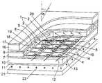
도 1 은 관련된 전자 제어 장치를 갖지 않는 본 발명에 따른 액티브 매트릭스 액정 표시 장치의 구조에 대한 실시예이다. 상기 액티브 매트릭스 액정 표시 장치는 매트릭스의 행과 열로 배열된, 각각 적어도 2 개의 서브 화소(2 및 3)로 이루어진 화소(1)를 포함한다. 상기 서브 화소(2 및 3)는 각각 광투과성 서브 화소 전극(4 또는 5), 액티브 매트릭스 액정 표시 장치에 공통인 광투과성 기준 전극(6)의 화소(1)의 모든 부분 또는 적어도 한 부분, 그리고 서브 화소 전극(4 및 5)과 기준 전극(6)사이에 놓인 액정 층(7)으로 형성된다.1 is an embodiment of the structure of an active matrix liquid crystal display device according to the present invention without an associated electronic control device. The active matrix liquid crystal display device includes a pixel 1 composed of at least two
삭제delete
삭제delete
상기 서브 화소 전극(4 및 5)과 기준 전극(6)사이에 놓인 액정 층(7)의 각각의 영역은 다음부터 액정 하부 셀로 표시된다. 상기 액정 층(7)은 도메인(8 및 9)에서 액정의 가변적인 정렬을 통해 세분되고, 각 화소(1)의 상이한 서브 화소(2 및 3)에 상이한 도메인(8 및 9)이 할당된다. 도시된 실시예에 있어서, 액정이 상이하게 정렬된 2 개의 도메인(8 및 9)이 제공되고, 여기서 서브 화소(2 또는 3)의 수평으로 연장된 각각의 열에 각각 하나의 도메인(8 또는 9)이 할당된다.Each region of the
상기 서브 화소 전극(4 및 5)은 하부면에서 편광 필름(11)을 지지하는 유리 플레이트(10)의 상부면에서 형성된다. 또한 상기 유리 플레이트(10)의 상부면에 행 전극(12) 및 열 전극(13)은 상기 화소(1)의 각각의 행에 각각 행 전극(12)중 한 개가 할당되고, 화소(1)의 각각의 열에 각각 열 전극(13)중 한 개가 할당되도록 형성된다. 각 개별 화소(1)의 서브 화소 전극(4 및 5)은 제어 가능한 스위치를 통해 각각 할당된 열 전극(13)과 연결되고, 상기 스위치는 그의 제어 측에서 화소 제어 장치를 통해 각각 할당된 행 전극(12)에 접속된다. 여기서 도시된 실시예에 있어서, 얇은 필름 트랜지스터로 형성된 제어 가능한 스위치에 스위치를 제어하는 화소 제어 장치의 회로 부품(14 및 15)이 함께 제공된다.The
상기 광투과성 기준 전극(6)은 상부 유리 플레이트(16)로 커버되고, 상기 유리 플레이트(16)상에는 추가의 편광 필름(17)이 제공된다. 칼라 이미지의 디스플레이를 위해, 여기서 기준 전극(6)과 상부 유리 플레이트(11)사이에, 열마다 교환되는 레드, 그린 및 블루 칼라 필터 스트립(18,19 및 20)이 배열된다The light
이미지 재생을 위해서, 배경 조명(21)에 의한 빛(22)은 액정 층(7)을 통해 방사되어, 상기 액정 층 하부 셀로부터의 각각의 제어에 따라, 상이한 명도를 가진 행 전극 및 열 전극(12 및 13)을 통해 전달된다. 이 경우 빛(22)은 우선 하부 편광 필름(11)(편광자)에 의해 편광 된다. 개별 액정 하부 셀 내에서 각 서브 화소 전극(4 또는 5)과 기준 전극(6) 사이의 전압에 따라 액정이 광학적으로 왜곡됨으로써, 액정을 관통해 편광 되는 빛의 편광 방향이 이에 상응하게 회전된다. 편광 방향의 회전에 의해, 상부 편광 필름(17)(분광기)내에서 회전율에 따라, 밖으로 나온 빛의 명도가 다소 심하게 저하된다.For image reproduction, the light 22 by the
도 2 는 블록 회로도 형태의 본 발명에 따른 액티브 매트릭스 액정 표시 장치의 실시예를 도시한다. 매트릭스(24)의 행과 열에 각각 3 개의 서브 화소(26,27 및 28)로 이루어진 화소(25)가 배치된다. 각각의 서브 화소, 예컨대 26 은 서브 화소 전극(29), 매트릭스(24)의 모든 화소(25)에 공통인 기준 전극(30), 및 그 사이에 놓인 액정 하부 셀(31)로 형성된다. 상기 기준 전극(30)은 기준 전위(V0)에 놓인다. 상기 서브 화소 전극들(29)은 여기에 개별적으로 할당된 제어 가능한 스위치(32)를 통해, 관련된 화소(25) 및 모든 다른 화소의 동일한 열에 할당된 열 전극(33)에 공통으로 연결된다. 각각 하나의 화소(25)에 속해 있는 제어 가능한 스위치(32)는 제어 측에서 화소 제어 장치(34)에 접속되고, 상기 장치(34)는 그 측에서 관련된 화소(25) 및 모든 다른 화소의 동일한 행에 할당된 행 전극(35)에 접속된다.2 shows an embodiment of an active matrix liquid crystal display according to the present invention in the form of a block circuit diagram. In the rows and columns of the
상기 열 전극(33)은 열 제어 장치(36)에 접속되고, 상기 장치(36)는 거기에 공급된 화소 신호(37)에 의해, 동시에 각 하나의 행에 놓인 화소(25)에 대한 상이한 그레이 톤 신호(38)와 상이한 행의 화소(25)에 대한 시간 순차적인 상이한 그레이 톤 신호(38)를 발생시키고, 열 전극(33)에 인가된다. 행 전극(35)이 접속된 행 제어 장치(39)는 연속적으로 각각의 행에 대해 각각 제어 신호(40)를 발생시키고, 상기 제어 신호로 인해 관련 행에 있는 화소(25)의 제어를 위한 그레이 톤 신호(38)가 전달된다. 이 경우 2 개의 제어 장치(36 및 39)에 할당된 동기화 장치(67)는 상이한 행에 대한 시간 순차적인 그레이 톤 신호(38)와 개별 행에 대한 제어 신호(40)사이의 동기화를 제공한다.The
화소(25)를 각각 제어 할 경우, 화소를 형성하는 서브 화소(26,27 및 28)가 서로 독립적으로 제어 될 수 있기 위해서, 도 3,4 및 5 에 도시된 바와 같이, 그레이 톤 신호(38)는 각각 상이한 서브 화소(26,27 및 28)에 대한 시간 순차적인 상이한 그레이 톤 레벨(41,42 및 43)로 이루어진다. 상기 제어 신호(40)는 화소 제어 장치(34)내에서 제어 가능한 스위치(32)용으로 서로 세분된 연결 신호(44)로 변환되는 형태를 지님으로써, 상이한 그레이 톤 레벨(41,42 및 43)은 상이한 서브 화소 전극(29) 및 상이한 액정 하부 셀(31)에 전달된다.In the case of controlling the
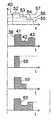
도 3 에 도시된 실시예에 있어서 상기 제어 신호(40)는 3 개의 연속된 신호 펄스(45,46 및 47)로 이루어지고, 상기 신호 펄스는 시프트 레지스터, 카운터 또는 직렬 병렬 변환기로 형성된 화소 제어 장치(34)로 부터 위치 및 시간적으로 연속되어 제어 가능한 스위치(32)에 연결 신호(44)로서 공급된다. 열 전극(33)으로부터 제어 가능한 스위치(32)를 통해 그레이 톤 레벨(41,42 및 43)을 가진 상이한 신호(48,49 및 50)가 상이한 서브 화소 전극(29)에 이르게 됨으로써, 관련 액정 하부 셀(31)에 상이한 전압이 충전되고, 다음 제어 때까지 유지된다. 상이한 전압에 상응하게 액정 하부 셀(31)에 있어서 상이한 광학적 투명도 또는 명도가 세팅된다. 예컨대 행 전극(35)에서의 방해 펄스에 의해 서브 화소 전극(29)에 대해 발생된 연결 신호(44)의 차례가 변경되는 것을 방지하기 위해, 각 제어 신호(40)는 추가로 동기화 펄스(51)를 포함하고, 상기 동기화 펄스는 형태, 세기, 지속 시간 또는 극성에 의해 나머지 신호 펄스(45,46 및 47)와 구별되고, 상기 동기화 펄스에 의해 화소 제어 장치 내에서의 신호 변환은 서브 화소(26,27 및 28)의 각각 새로운 제어시 동기화된다.In the embodiment shown in Fig. 3, the
도 4 에 도시된 실시예에 있어서, 상기 제어 신호(40)는 단계적으로 더 낮게 형성된 신호 레벨(52,53 및 54)을 가진 3 개의 연속된 부분 신호로 이루어진다. 화소 제어 장치(34) 내에서, 제어 신호(40)는 개별적으로 제어 가능한 스위치(32)에 할당되고, 초과할 경우에 각각 할당된 제어 가능한 스위치(32)가 연결되는, 3 개의 상이한 한계값(55,56 및 57)과 비교된다. 신호 레벨(52)을 가진 부분 신호는 각각의 한계값(55,56 및 57)을 초과함으로써, 맨 먼저 각각의 제어 가능한 스위치(32)가 연결된다. 다음으로 신호 레벨(53)을 가진 부분 신호는 단지 한계값(55 및 56)만을 초과함으로써, 한계값(52)이 할당된 제어 가능한 스위치(32)가 오프된다. 신호 레벨(54)을 가진 마지막 부분 신호에 있어서, 단지 한계값(55)만이 초과됨으로써, 단지 각각 할당된 제어 가능한 스위치(32)가 연결된다. 열 전극(33)으로부터 제어 가능한 스위치(32)를 통해 그레이 톤 신호(38)의 상이한 신호 부분(58,59 및 60)이 상이한 서브 화소 전극(29)에 이르고, 상이한 그레이 톤 레벨(41,42 및 43)은 관련 액정 하부 셀(31)에 충전되는 전압에 대해 제어 가능한 스위치(32)의 각 연결 시간의 종결부에서 결정된다.In the embodiment shown in FIG. 4, the
도 5 에 도시된 실시예에 있어서, 제어 신호(40)는 마찬가지로 상이한 신호 레벨(61,62 및 63)을 가진 3 개의 연속된 부분 신호로 이루어진다. 이미 기술된 실시예와는 반대로, 화소 제어 장치(34)내에서 제어 신호(40)는 한계값(55,56 및 57)을 초과하는 것에 대해서만 아니라, 개별 한계값(56 및 57)이 초과되는지 아닌지에 대해서도 검사됨으로써, 화소 제어 장치(34)는 윈도우 컴퍼레이터로서 작동된다. 도시된 실시예에 있어서, 3 개의 제어 가능한 스위치(32)는 신호 레벨(61)을 가진 부분 신호가 가장 낮은 한계값(55)을 초과하고, 중간 한계값(56)을 초과하는지, 신호 레벨(62)을 가진 부분 신호가 중간 한계값(56)을 초과하고, 높은 한계값(57)을 초과하는지, 신호 레벨(63)을 가진 부분 신호가 높은 한계값(57)을 초과하는지에 따라 각각 작동된다. 열 전극(33)으로부터 제어 가능한 스위치(32)를 통해 상이한 그레이 톤 레벨(41,42 및 43)을 가진 그레이 톤 신호(38)의 상이한 신호 부분(64,65 및 66)이 상이한 서브 화소 전극(29)에 이른다.In the embodiment shown in FIG. 5, the
도 6 은 예컨대 각각 4 개의 서브 화소(95)로 이루어진 화소(96)를 가진 액티브 매트릭스 액정 표시 장치에 있어서, 할당된 제어 가능한 스위치(얇은 필름 트랜지스터)(98) 및 화소 제어 장치(99)와 함께 서브 화소 전극(97)이 공통 캐리어(100)상에 배치될 수 있는 것을 도시한다. L 형으로 형성된 서브 화소 전극(97)은 리세스(101)가 각각의 화소(96)에 속한 행 전극(102) 및 열 전극(103)이 교차되는 자유 영역을 형성하도록 서로 마주 놓인다. 개별 리세스(101)내에 제어 가능한 스위치(98)가 배치되고, 상기 스위치를 통해 서브 화소 전극(97)이 열 전극(103)과 연결된다. 또한 개별 리세스(101)내에 할당된 제어 가능한 스위치(98)가 제어되는 화소 제어 장치(99)의 회로 부분(104)이 배치된다. 도시된 실시예에 있어서, 화소 제어 장치(99)는 입력부측에서 행 전극(102)과 접속되고, 화소 제어 장치(99)의 개별 회로 부분(104)에 상응하는 연속된 레지스터 위치를 갖는 시프트 레지스터로 이루어진다.FIG. 6 shows an active matrix liquid crystal display having, for example, a
동일한 수의 행 전극 및 열 전극에 있어서, 또한 독립적으로 서로 제어 가능한 서브 화소에 의해, 종래의 액티브 매트릭스 액정 표시 장치와 비교하여 더 많은 이미지 정보가 디스플레이될 수 있다. 따라서 도 2 에 따른 실시예에 있어서, 개별 화소(25)의 칼라 이미지 재생을 위해, 각각의 레드, 그린 및 블루 칼라 필터(68,69 및 70)가 빛(22)의 방사 경로에서 관련 서브 화소(26,27 및 28)의 앞이나 뒤에 배치될 수 있다.In the same number of row electrodes and column electrodes, and also by sub-pixels independently controllable to each other, more image information can be displayed in comparison with a conventional active matrix liquid crystal display device. Thus, in the embodiment according to FIG. 2, for the color image reproduction of the
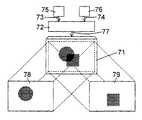
도 7 은 본 발명에 따른 액티브 매트릭스 액정 표시 장치(71)의 추가 실시예를 도시하고, 개별 화소는 각각 상이하게 정렬된 액정을 가지는 액정 층의 상이한 도메인이 할당된 2 개의 서브 화소로 이루어진다. 이것에 대한 실시예가 도 1 에 의해 이미 기술되었다. 상기 매트릭스 액정 표시 장치(71)에 열 제어 장치(36)의 부품인 신호 처리 장치(72)를 통해, 이미지 신호(73 및 74)가 2 개의 상이한 이미지 신호원(75 및 76)으로부터 공급된다. 상기 신호 처리 장치(72)는 2 개의 상이한 이미지 신호(73 및 74)를 이미지 신호(74)의 그레이 톤 레벨에 이어지는 이미지 신호(73)의 그레이 톤 레벨로 이루어진 하나의 이미지 신호(77)에 결합시킨다. 이것은 가장 간단한 방법으로, 이미지 신호(73 및 74)의 시퀀스에 비해 2배인 주파수가 이미지 신호(73 및 74)사이에서 전환됨으로써 일어난다. 도 2 내지 도 5 에 따라 기술된 바와 같이, 상기 액티브 매트릭스 표시 장치(71)의 각각의 개별 화소의 2 개의 서브 화소 중에 이미지 신호(73)의 그레이 톤 레벨을 갖는 하나와 이미지 신호(74)의 그레이 톤 레벨을 갖는 서브 화소가 제어된다. 이러한 방법으로 상기 액티브 매트릭스 액정 표시 장치(71) 중에 2 개의 상이한, 서브 화소마다 삽입된 이미지(78 및 79)가 발생되고, 상기 이미지는 마찬가지로 서브 화소마다 액정 층이 액정이 상이하게 정렬된 상이한 도메인으로 세분됨으로써, 상이한 시야 범위에서 보여질 수 있게된다.Fig. 7 shows a further embodiment of the active matrix
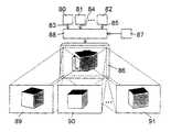
도 8 은 다수의 이미지 신호원(80,81 및 82)이 이미지 신호(83,84 및 85)를 3 차원 물체의 상이한 시점으로부터 공급하는 실시예를 도시한다. 여기서 사용된 액티브 매트릭스 액정 표시 장치(86)에 있어서, 화소 및 액정 층은 이미지 신호원(80,81 및 82)수에 상응하는 서브 화소 또는 상기 서브 화소에 할당되면서 상이하게 정렬된 액정을 가지는 도메인을 갖는다. 상기 이미지 신호(83,84 및 85)는 상기 액티브 매트릭스 표시 장치(86)에 세팅 장치(87)에 의해 제어된 변환 장치(88)를 통해 공급된다. 상기 세팅 장치(87)에 의해, 상기 변환 장치(88)의 상이한 연결 위치가 세팅될 수 있음으로써, 상기 액티브 매트릭스 액정 표시 장치(86)로부터 3 차원 물체를 상이한 시점으로 표시되는 상이한 이미지(89,90 및 91) 및 상이한 시야 범위에 대해 생성되고, 이러한 방법으로 물체의 3 차원 디스플레이가 이루어진다. 물론 도 7 에 의해 기술된 바와 같이, 상이한 이미지(89,90 및 91)도 동시에 디스플레이될 수도 있다.8 illustrates an embodiment where multiple
상이한 시야 범위에 대한 다수의 상이한 이미지를 표시하는 대신에, 동일한 방법으로, 동일한 이미지는 선택에 따라 예컨대 2 개의 상이한 시야 범위 중 하나에서, 또는 다른 시야 범위에서, 아니면 2 개의 시야 범위에 모두에 대해 디스플레이되는 것이 가능하다. 따라서 자동차에서 액티브 매트릭스 액정 표시 장치를 설치할 경우에 디스플레이되는 이미지는 운전 중에 운전자의 시야 범위에서는 보이지 않고, 그와 반대로 동승자에게는 보일 수 있게 된다. 도 9 는 자동차 내에서 운전자의 좌석(93)과 동승자의 좌석(94) 앞의 대략 중간 지점에 액티브 매트릭스 액정 표시 장치(92)를 설치하는 것에 대한 실시예를 도시한다.Instead of displaying a number of different images for different viewing ranges, in the same way, the same image is optionally chosen, for example, in one of two different viewing ranges, or in another viewing range, or for both viewing ranges. It is possible to be displayed. Therefore, when the active matrix liquid crystal display is installed in an automobile, the image displayed is not visible in the driver's field of view while driving, and vice versa. FIG. 9 shows an embodiment for installing the active matrix
먼저 기술된 본 발명에 따른 액티브 매트릭스 액정 표시 장치의 실시예에 있어서, 디스플레이된 이미지가 관찰자에게 보여 질 수 있는 상이한 시야 범위의 세팅은 서브 화소에 할당된 도메인 내에 상이하게 정렬된 액정을 가진 서브 화소가 독립적으로 서로 제어됨으로써 이루어진다. 이것에 대해 보충적으로 또는 대안적으로 시야 범위는 기준 전극에 인가된 기준 전위와 서브 화소 전극에 전달된 그레이 톤 레벨의 전위 레벨 사이의 전위차의 변경에 의해 세팅될 수 있다.In the embodiment of the active matrix liquid crystal display according to the present invention described above, the setting of the different viewing ranges in which the displayed image can be shown to the observer has sub-pixels having liquid crystals arranged differently in the domain assigned to the sub-pixels. Is achieved by controlling each other independently. In addition or alternatively to this, the viewing range can be set by changing the potential difference between the reference potential applied to the reference electrode and the potential level of the gray tone level delivered to the sub pixel electrode.
즉 도 10 이 도시된 바와 같이, 액티브 매트릭스 표시 장치로부터 방사된 빛의 명도(H) 및 각각 디스플레이된 이미지의 명암은 시점
따라서 도 2 에 도시된 액티브 매트릭스 표시 장치에 있어서, 예컨대 도 11에 도시된 바와 같이 시간적으로 연속되고, 개별 서브 화소(26,27 및 28)의 제어를 위해 사용되는 그레이 톤 신호(38)의 그레이 톤 레벨(41,42 및 43)이 평균 그레이 톤 레벨(106)이 적어도 거의 유지되는 상태에서 변경될 수 있는 세팅 장치(105)가 제공된다. 이러한 방법으로 개별 서브 화소(26,27 및 28)의 시점에 따른 명도는 각각 개별 서브 화소로 형성된 화소(25)의 명도가 전체적으로 변경되지 않을 때 변경된다.Thus, in the active matrix display device shown in FIG. 2, for example, the gray of the
그러나 도 12 가 도시한 바와 같이, 액정 셀 또는 액정 하부 셀(31)의 명도(H) 또는 동일한 의미로 광학적 투명도와 액정 셀에 각각 인가된 전압(U)사이의 의존 관계는 전형적으로 비선형이다. 통상적으로 액정 셀은 상기 의존도가 계속해서 선형으로 존재하는 전압 범위내에서 작동된다. 다음에 설명되는 것처럼, 비선형 범위 내에서 이미지 재생은 왜곡될 수 있다. 예컨대 동시에 3 개의 상이한 액정 셀에 의해 발생되는 3 개의 상이한 화소(X,Y 및 Z)가 관찰되고, 화소(Z)는 일정 값(


따라서 도 2 에 도시된 바와 같이, 상기 행 제어 장치(36)는 그레이 톤 신호(38')가 열 전극(33)에 인가되기 전에, 액정 셀(31)의 광학적 투명도와 액정 셀에 인가되는 전압(U) 사이의 도 12 에 도시된 전형적 의존도에 대한 정보를 기초로 하여, 그레이 톤 신호(38')와 기준 전위(V0) 사이의 전위차에 따라, 액정 셀(31)의 광학적 투명도와 왜곡되지 않은 그레이 톤 신호(38') 사이의 관계가 거의 선형적 결합을 하는 방식으로 왜곡되는 보정 장치(107)를 포함한다.Thus, as shown in FIG. 2, the
도 12에는 곡선(K)이 도시되며, 상기 곡선에 상응하여 보정 장치(107)에서 전압(U')을 가진 왜곡되지 않은 그레이 톤 신호(38')가 전압(U)을 가진 왜곡된 그레이 톤 신호(38)로 변환될 수 있다. 이러한 변환은 또한 디지털로 이루어질 수 있고, 상기 곡선(K)은 테이블 값 형태로 여기서는 도시되지 않은 메모리에 존재한다.A curve K is shown in FIG. 12, where the undistorted
Claims (10)
Translated fromKoreanApplications Claiming Priority (2)
| Application Number | Priority Date | Filing Date | Title |
|---|---|---|---|
| DE19811022ADE19811022A1 (en) | 1998-03-13 | 1998-03-13 | Active matrix LCD |
| DE19811022.7 | 1998-03-13 |
Publications (2)
| Publication Number | Publication Date |
|---|---|
| KR20010041711A KR20010041711A (en) | 2001-05-25 |
| KR100604705B1true KR100604705B1 (en) | 2006-07-28 |
Family
ID=7860845
Family Applications (1)
| Application Number | Title | Priority Date | Filing Date |
|---|---|---|---|
| KR1020007009934AExpired - Fee RelatedKR100604705B1 (en) | 1998-03-13 | 1999-03-11 | Active matrix liquid crystal display |
Country Status (6)
| Country | Link |
|---|---|
| US (1) | US6633306B1 (en) |
| EP (1) | EP1062652B1 (en) |
| JP (1) | JP2002507774A (en) |
| KR (1) | KR100604705B1 (en) |
| DE (2) | DE19811022A1 (en) |
| WO (1) | WO1999048080A1 (en) |
Families Citing this family (39)
| Publication number | Priority date | Publication date | Assignee | Title |
|---|---|---|---|---|
| US8139050B2 (en) | 1995-07-20 | 2012-03-20 | E Ink Corporation | Addressing schemes for electronic displays |
| DE10022630A1 (en)* | 2000-05-11 | 2001-11-15 | Mannesmann Vdo Ag | Process for displaying images on a liquid crystal cell |
| US7401923B2 (en)* | 2004-03-09 | 2008-07-22 | Fergason Patent Properties, Llc | Monitor for showing high-resolution and three-dimensional images and method |
| US20060268407A1 (en)* | 2000-07-07 | 2006-11-30 | Fergason James L | Display system using two displays and polarization direction rotation for showing high-resolution and three-dimensional images and method and use of a DBEF beam splitter |
| JP4538915B2 (en)* | 2000-07-24 | 2010-09-08 | セイコーエプソン株式会社 | Driving method of electro-optical device |
| TW518552B (en) | 2000-08-18 | 2003-01-21 | Semiconductor Energy Lab | Liquid crystal display device, method of driving the same, and method of driving a portable information device having the liquid crystal display device |
| JP2004522179A (en)* | 2000-11-29 | 2004-07-22 | イー−インク コーポレイション | Addressing scheme for electronic displays |
| GB0109015D0 (en) | 2001-04-11 | 2001-05-30 | Koninkl Philips Electronics Nv | Bistable chiral nematic liquid crystal display and method of driving the same |
| DE10148212A1 (en)* | 2001-09-28 | 2003-04-03 | Siemens Ag | Display unit has at least one image point controlled to be dark after each predefined number of immediately adjacent image point elements in rows/columns controlled for image reproduction |
| US6680579B2 (en)* | 2001-12-14 | 2004-01-20 | Hewlett-Packard Development Company, L.P. | Method and apparatus for image and video display |
| GB0130600D0 (en)* | 2001-12-21 | 2002-02-06 | Koninkl Philips Electronics Nv | Active matrix electroluminescent display device |
| KR100890022B1 (en)* | 2002-07-19 | 2009-03-25 | 삼성전자주식회사 | LCD and its driving method |
| US20130063333A1 (en) | 2002-10-16 | 2013-03-14 | E Ink Corporation | Electrophoretic displays |
| KR100942833B1 (en)* | 2002-12-20 | 2010-02-18 | 엘지디스플레이 주식회사 | LCD and its driving device |
| US7046256B2 (en)* | 2003-01-22 | 2006-05-16 | Clairvoyante, Inc | System and methods of subpixel rendering implemented on display panels |
| KR100922788B1 (en)* | 2003-02-19 | 2009-10-21 | 엘지디스플레이 주식회사 | LCD and its driving method |
| KR100933446B1 (en)* | 2003-06-20 | 2009-12-23 | 엘지디스플레이 주식회사 | Driving device and driving method of liquid crystal display |
| US7161728B2 (en)* | 2003-12-09 | 2007-01-09 | Idc, Llc | Area array modulation and lead reduction in interferometric modulators |
| US7889163B2 (en) | 2004-08-27 | 2011-02-15 | Qualcomm Mems Technologies, Inc. | Drive method for MEMS devices |
| US7136213B2 (en) | 2004-09-27 | 2006-11-14 | Idc, Llc | Interferometric modulators having charge persistence |
| US8310441B2 (en) | 2004-09-27 | 2012-11-13 | Qualcomm Mems Technologies, Inc. | Method and system for writing data to MEMS display elements |
| WO2006060236A2 (en)* | 2004-11-23 | 2006-06-08 | Fergason Patent Properties, Llc | Monitor for showing high-resolution and three-dimensional images |
| US7411636B2 (en) | 2004-11-23 | 2008-08-12 | Fergason Patent Properties, Llc | Stereoscopic liquid crystal display (LCD) with polarization method |
| DE102005001963A1 (en)* | 2005-01-15 | 2005-12-22 | Audi Ag | Display screen for motor vehicle has display area and control unit, which controls display of video signal on display area depending on angle of rotation of display screen around its rotating axis and speed of vehicle |
| US9318053B2 (en)* | 2005-07-04 | 2016-04-19 | Semiconductor Energy Laboratory Co., Ltd. | Semiconductor device and driving method thereof |
| US7702192B2 (en) | 2006-06-21 | 2010-04-20 | Qualcomm Mems Technologies, Inc. | Systems and methods for driving MEMS display |
| US7777715B2 (en) | 2006-06-29 | 2010-08-17 | Qualcomm Mems Technologies, Inc. | Passive circuits for de-multiplexing display inputs |
| US20090225036A1 (en)* | 2007-01-17 | 2009-09-10 | Wright David G | Method and apparatus for discriminating between user interactions |
| US7403180B1 (en)* | 2007-01-29 | 2008-07-22 | Qualcomm Mems Technologies, Inc. | Hybrid color synthesis for multistate reflective modulator displays |
| US8451298B2 (en)* | 2008-02-13 | 2013-05-28 | Qualcomm Mems Technologies, Inc. | Multi-level stochastic dithering with noise mitigation via sequential template averaging |
| US8736590B2 (en) | 2009-03-27 | 2014-05-27 | Qualcomm Mems Technologies, Inc. | Low voltage driver scheme for interferometric modulators |
| DE102009023897A1 (en) | 2009-06-04 | 2010-12-09 | Volkswagen Ag | Method for operating a display device for view page-specific information displays and operating device therefor |
| WO2010141766A1 (en) | 2009-06-05 | 2010-12-09 | Qualcomm Mems Technologies, Inc. | System and method for improving the quality of halftone video using a fixed threshold |
| KR101354386B1 (en) | 2010-12-07 | 2014-01-23 | 엘지디스플레이 주식회사 | Liquid crystal display |
| CN102879968B (en)* | 2012-10-26 | 2014-11-05 | 深圳市华星光电技术有限公司 | Liquid crystal display driving circuit |
| US9928371B2 (en) | 2014-11-19 | 2018-03-27 | Papal, Inc. | Systems and methods for protecting information displayed on a user interface of a device |
| US9886598B2 (en) | 2014-12-29 | 2018-02-06 | Paypal, Inc. | Automatic adjustment of a display to obscure data |
| CN104952412B (en)* | 2015-07-15 | 2018-04-13 | 深圳市华星光电技术有限公司 | The driving method and driving device of liquid crystal panel |
| US9928372B2 (en)* | 2015-10-23 | 2018-03-27 | Paypal, Inc. | Selective screen privacy |
Family Cites Families (4)
| Publication number | Priority date | Publication date | Assignee | Title |
|---|---|---|---|---|
| FR2606194B1 (en)* | 1986-11-05 | 1989-02-17 | Commissariat Energie Atomique | MATRIX DISPLAY DEVICE AND CONTROL METHOD THEREOF |
| GB2205191A (en)* | 1987-05-29 | 1988-11-30 | Philips Electronic Associated | Active matrix display system |
| JP2515887B2 (en)* | 1989-08-04 | 1996-07-10 | 株式会社日立製作所 | Matrix display |
| US5717474A (en)* | 1994-09-30 | 1998-02-10 | Honeywell Inc. | Wide-viewing angle multi-domain halftone active matrix liquid crystal display having compensating retardation |
- 1998
- 1998-03-13DEDE19811022Apatent/DE19811022A1/ennot_activeWithdrawn
- 1999
- 1999-03-11KRKR1020007009934Apatent/KR100604705B1/ennot_activeExpired - Fee Related
- 1999-03-11USUS09/623,817patent/US6633306B1/ennot_activeExpired - Fee Related
- 1999-03-11JPJP2000537198Apatent/JP2002507774A/enactivePending
- 1999-03-11DEDE59902343Tpatent/DE59902343D1/ennot_activeExpired - Fee Related
- 1999-03-11EPEP99916781Apatent/EP1062652B1/ennot_activeExpired - Lifetime
- 1999-03-11WOPCT/DE1999/000680patent/WO1999048080A1/enactiveIP Right Grant
Also Published As
| Publication number | Publication date |
|---|---|
| WO1999048080A1 (en) | 1999-09-23 |
| KR20010041711A (en) | 2001-05-25 |
| EP1062652B1 (en) | 2002-08-14 |
| US6633306B1 (en) | 2003-10-14 |
| DE59902343D1 (en) | 2002-09-19 |
| EP1062652A1 (en) | 2000-12-27 |
| JP2002507774A (en) | 2002-03-12 |
| DE19811022A1 (en) | 1999-09-16 |
Similar Documents
| Publication | Publication Date | Title |
|---|---|---|
| KR100604705B1 (en) | Active matrix liquid crystal display | |
| KR100604704B1 (en) | Active matrix liquid crystal display | |
| EP0284134B1 (en) | Method of driving a liquid crystal display device and associated display device | |
| US9711078B2 (en) | Display device | |
| US5032007A (en) | Apparatus and method for an electronically controlled color filter for use in information display applications | |
| JP3266288B2 (en) | Display device and operation method thereof | |
| JP4136243B2 (en) | Time-series scanning display | |
| US9083965B2 (en) | Stereoscopic display device | |
| US20030132901A1 (en) | Field sequential color display device | |
| US7307609B2 (en) | Method and apparatus for stereoscopic display employing a reflective active-matrix liquid crystal pixel array | |
| CA2223371C (en) | Frame display control in an image display having a liquid crystal display panel | |
| US20070035493A1 (en) | Method and apparatus for stereoscopic display employing a reflective active-matrix liquid crystal pixel array | |
| US6177914B1 (en) | Plasma addressed electro-optical display | |
| EP0324997A1 (en) | Method of driving a display device | |
| US5278681A (en) | Combined color and monochrome display | |
| GB2343980A (en) | Spatial light modulator and display | |
| US6005645A (en) | Stereoscopic display device having particular circuits | |
| US8629821B2 (en) | Display device with faster changing side image | |
| JP2001042283A (en) | Image display device | |
| US6304242B1 (en) | Method and apparatus for displaying image | |
| JPH02118521A (en) | liquid crystal display device | |
| KR100503430B1 (en) | field sequential liquid crystal device | |
| US6473092B1 (en) | Apparatus and method for color illumination in display devices | |
| CA2164803C (en) | Method and circuit for driving picture display devices | |
| JP3602395B2 (en) | Projection type display device |
Legal Events
| Date | Code | Title | Description |
|---|---|---|---|
| E13-X000 | Pre-grant limitation requested | St.27 status event code:A-2-3-E10-E13-lim-X000 | |
| PA0105 | International application | St.27 status event code:A-0-1-A10-A15-nap-PA0105 | |
| PG1501 | Laying open of application | St.27 status event code:A-1-1-Q10-Q12-nap-PG1501 | |
| A201 | Request for examination | ||
| P11-X000 | Amendment of application requested | St.27 status event code:A-2-2-P10-P11-nap-X000 | |
| P13-X000 | Application amended | St.27 status event code:A-2-2-P10-P13-nap-X000 | |
| PA0201 | Request for examination | St.27 status event code:A-1-2-D10-D11-exm-PA0201 | |
| E902 | Notification of reason for refusal | ||
| PE0902 | Notice of grounds for rejection | St.27 status event code:A-1-2-D10-D21-exm-PE0902 | |
| P11-X000 | Amendment of application requested | St.27 status event code:A-2-2-P10-P11-nap-X000 | |
| P13-X000 | Application amended | St.27 status event code:A-2-2-P10-P13-nap-X000 | |
| E701 | Decision to grant or registration of patent right | ||
| PE0701 | Decision of registration | St.27 status event code:A-1-2-D10-D22-exm-PE0701 | |
| GRNT | Written decision to grant | ||
| PR0701 | Registration of establishment | St.27 status event code:A-2-4-F10-F11-exm-PR0701 | |
| PR1002 | Payment of registration fee | St.27 status event code:A-2-2-U10-U12-oth-PR1002 Fee payment year number:1 | |
| PG1601 | Publication of registration | St.27 status event code:A-4-4-Q10-Q13-nap-PG1601 | |
| LAPS | Lapse due to unpaid annual fee | ||
| PC1903 | Unpaid annual fee | St.27 status event code:A-4-4-U10-U13-oth-PC1903 Not in force date:20090720 Payment event data comment text:Termination Category : DEFAULT_OF_REGISTRATION_FEE | |
| PC1903 | Unpaid annual fee | St.27 status event code:N-4-6-H10-H13-oth-PC1903 Ip right cessation event data comment text:Termination Category : DEFAULT_OF_REGISTRATION_FEE Not in force date:20090720 | |
| R18-X000 | Changes to party contact information recorded | St.27 status event code:A-5-5-R10-R18-oth-X000 | |
| R18-X000 | Changes to party contact information recorded | St.27 status event code:A-5-5-R10-R18-oth-X000 |