KR100604271B1 - Liquid crystal display - Google Patents
Liquid crystal displayDownload PDFInfo
- Publication number
- KR100604271B1 KR100604271B1KR1020000060821AKR20000060821AKR100604271B1KR 100604271 B1KR100604271 B1KR 100604271B1KR 1020000060821 AKR1020000060821 AKR 1020000060821AKR 20000060821 AKR20000060821 AKR 20000060821AKR 100604271 B1KR100604271 B1KR 100604271B1
- Authority
- KR
- South Korea
- Prior art keywords
- common voltage
- thin film
- film transistor
- gate
- transistor array
- Prior art date
- Legal status (The legal status is an assumption and is not a legal conclusion. Google has not performed a legal analysis and makes no representation as to the accuracy of the status listed.)
- Expired - Fee Related
Links
Images


Classifications
- G—PHYSICS
- G02—OPTICS
- G02F—OPTICAL DEVICES OR ARRANGEMENTS FOR THE CONTROL OF LIGHT BY MODIFICATION OF THE OPTICAL PROPERTIES OF THE MEDIA OF THE ELEMENTS INVOLVED THEREIN; NON-LINEAR OPTICS; FREQUENCY-CHANGING OF LIGHT; OPTICAL LOGIC ELEMENTS; OPTICAL ANALOGUE/DIGITAL CONVERTERS
- G02F1/00—Devices or arrangements for the control of the intensity, colour, phase, polarisation or direction of light arriving from an independent light source, e.g. switching, gating or modulating; Non-linear optics
- G02F1/01—Devices or arrangements for the control of the intensity, colour, phase, polarisation or direction of light arriving from an independent light source, e.g. switching, gating or modulating; Non-linear optics for the control of the intensity, phase, polarisation or colour
- G02F1/13—Devices or arrangements for the control of the intensity, colour, phase, polarisation or direction of light arriving from an independent light source, e.g. switching, gating or modulating; Non-linear optics for the control of the intensity, phase, polarisation or colour based on liquid crystals, e.g. single liquid crystal display cells
- G02F1/133—Constructional arrangements; Operation of liquid crystal cells; Circuit arrangements
- G02F1/136—Liquid crystal cells structurally associated with a semi-conducting layer or substrate, e.g. cells forming part of an integrated circuit
- G—PHYSICS
- G02—OPTICS
- G02F—OPTICAL DEVICES OR ARRANGEMENTS FOR THE CONTROL OF LIGHT BY MODIFICATION OF THE OPTICAL PROPERTIES OF THE MEDIA OF THE ELEMENTS INVOLVED THEREIN; NON-LINEAR OPTICS; FREQUENCY-CHANGING OF LIGHT; OPTICAL LOGIC ELEMENTS; OPTICAL ANALOGUE/DIGITAL CONVERTERS
- G02F1/00—Devices or arrangements for the control of the intensity, colour, phase, polarisation or direction of light arriving from an independent light source, e.g. switching, gating or modulating; Non-linear optics
- G02F1/01—Devices or arrangements for the control of the intensity, colour, phase, polarisation or direction of light arriving from an independent light source, e.g. switching, gating or modulating; Non-linear optics for the control of the intensity, phase, polarisation or colour
- G02F1/13—Devices or arrangements for the control of the intensity, colour, phase, polarisation or direction of light arriving from an independent light source, e.g. switching, gating or modulating; Non-linear optics for the control of the intensity, phase, polarisation or colour based on liquid crystals, e.g. single liquid crystal display cells
- G02F1/133—Constructional arrangements; Operation of liquid crystal cells; Circuit arrangements
- G02F1/1333—Constructional arrangements; Manufacturing methods
- G02F1/1345—Conductors connecting electrodes to cell terminals
- G—PHYSICS
- G02—OPTICS
- G02F—OPTICAL DEVICES OR ARRANGEMENTS FOR THE CONTROL OF LIGHT BY MODIFICATION OF THE OPTICAL PROPERTIES OF THE MEDIA OF THE ELEMENTS INVOLVED THEREIN; NON-LINEAR OPTICS; FREQUENCY-CHANGING OF LIGHT; OPTICAL LOGIC ELEMENTS; OPTICAL ANALOGUE/DIGITAL CONVERTERS
- G02F1/00—Devices or arrangements for the control of the intensity, colour, phase, polarisation or direction of light arriving from an independent light source, e.g. switching, gating or modulating; Non-linear optics
- G02F1/01—Devices or arrangements for the control of the intensity, colour, phase, polarisation or direction of light arriving from an independent light source, e.g. switching, gating or modulating; Non-linear optics for the control of the intensity, phase, polarisation or colour
- G02F1/13—Devices or arrangements for the control of the intensity, colour, phase, polarisation or direction of light arriving from an independent light source, e.g. switching, gating or modulating; Non-linear optics for the control of the intensity, phase, polarisation or colour based on liquid crystals, e.g. single liquid crystal display cells
- G02F1/133—Constructional arrangements; Operation of liquid crystal cells; Circuit arrangements
- G02F1/1333—Constructional arrangements; Manufacturing methods
- G02F1/1343—Electrodes
- G02F1/134309—Electrodes characterised by their geometrical arrangement
- G02F1/134363—Electrodes characterised by their geometrical arrangement for applying an electric field parallel to the substrate, i.e. in-plane switching [IPS]
Landscapes
- Physics & Mathematics (AREA)
- Nonlinear Science (AREA)
- Mathematical Physics (AREA)
- Chemical & Material Sciences (AREA)
- Crystallography & Structural Chemistry (AREA)
- General Physics & Mathematics (AREA)
- Optics & Photonics (AREA)
- Liquid Crystal (AREA)
- Engineering & Computer Science (AREA)
- Microelectronics & Electronic Packaging (AREA)
- Control Of Indicators Other Than Cathode Ray Tubes (AREA)
- Liquid Crystal Display Device Control (AREA)
Abstract
Translated fromKoreanDescription
Translated fromKorean도 1은 통상적인 IPS모드 액정 표시소자를 도시한 평면도.1 is a plan view showing a conventional IPS mode liquid crystal display device.
도 2는 도 1에 도시된 액정 표시소자를 B-B'로 절단하여 도시한 단면도.FIG. 2 is a cross-sectional view of the liquid crystal display shown in FIG. 1 cut along line B-B '. FIG.
도 3은 도 1에 도시된 액정 표시소자의 구동특성을 도시한 단면도.3 is a cross-sectional view showing driving characteristics of the liquid crystal display shown in FIG. 1.
도 4는 도 1에 도시된 액정 표시소자의 구동회로를 간략하게 도시한 평면도.4 is a plan view briefly illustrating a driving circuit of the liquid crystal display shown in FIG. 1;
도 5는 본 발명의 제 1 실시예에 따른 액정 표시소자의 구동회로를 간략하게 도시한 평면도.5 is a plan view briefly showing a driving circuit of a liquid crystal display device according to a first embodiment of the present invention;
도 6은 본 발명의 제 2 실시예에 따른 액정 표시소자의 구동회로를 간략하게 도시한 평면도.6 is a plan view briefly showing a driving circuit of a liquid crystal display device according to a second embodiment of the present invention;
도 7은 본 발명의 제 3 실시예에 따른 액정 표시소자의 구동회로를 간략하게 도시한 평면도.7 is a plan view briefly showing a driving circuit of a liquid crystal display device according to a third embodiment of the present invention;
< 도면의 주요 부분에 대한 부호의 설명 ><Description of Symbols for Main Parts of Drawings>
80,102,122,142 : 공통전압패드 82,104,124,146 : 데이터패드 80,102,122,142: Common voltage pad 82,104,124,146: Data pad
83,117,134 : 데이터라인 84,106,126,155 : 게이트패드 83,117,134: Data lines 84,106,126,155: Gate pad
85,115,132 : 게이트라인 86,110,130 : 게이트링크 85,115,132: Gate line 86,110,130: Gate link
87,112,128,150,151 : 공통전압라인 90,108,127,140 : TFT 어레이 87,112,128,150,151: Common voltage line 90,108,127,140: TFT array
93,113,133,148 : 액정 32,100,120,141 : 배면기판 93,113,133,148: liquid crystal 32,100,120,141: back substrate
136,144 : 더미패드 138,152 : 더미신호라인 136,144: Dummy pad 138,152: Dummy signal line
본 발명은 액정 표시소자에 관한 것으로서, 특히 인 플레인 스위치 모드에 있어서, 박막트랜지스터 어레이 외곽부에 발생되는 얼룩을 제거하기 위한 액정 표시소자에 관한 것이다.BACKGROUND OF THE INVENTION 1. Field of the Invention The present invention relates to a liquid crystal display device, and more particularly to a liquid crystal display device for removing unevenness generated in an outer portion of a thin film transistor array in an in-plane switch mode.
본 발명은 박막트랜지스터 어레이 영역으로 인가되는 공통전압의 시간지연을 최소화하기 위한 액정 표시소자에 관한 것이다.The present invention relates to a liquid crystal display device for minimizing time delay of a common voltage applied to a thin film transistor array region.
액티브 매트릭스(Active Matrix) 구동방식의 액정 표시소자는 스위칭 소자로서 박막트랜지스터(Thin Film Transistor : 이하 "TFT"라 함)를 이용하여 자연스러운 동화상을 표시하고 있다. 이러한 액정 표시소자는 브라운관에 비하여 소형화가 가능하여 휴대용 텔레비젼(Television), 노트북 컴퓨터나 랩탑(Lap-Top)형 퍼스널 컴퓨터(Personal Computer) 등의 모니터로서 상품화되고 있다.The liquid crystal display of the active matrix driving method displays a natural moving image using a thin film transistor (hereinafter referred to as TFT) as a switching element. Such liquid crystal display devices can be miniaturized compared to CRTs and are commercialized as monitors such as portable televisions, notebook computers, and laptop-type personal computers.
액티브 매트릭스 타입의 액정 표시소자는 화소들이 게이트라인들과 데이터라인들의 교차부들 각각에 배열되어진 화소매트릭스(Picture Element Matrix 또는 Pixel Matrix)에 텔레비전 신호와 같은 비디오신호에 해당하는 화상을 표시하게 된 다. 화소들 각각은 데이터라인으로부터의 데이터신호의 전압레벨에 따라 투과 광량을 조절하는 액정셀을 포함한다. TFT는 게이트라인과 데이터라인들의 교차부에 설치되어 게이트라인으로부터의 스캔신호(게이트펄스)에 응답하여 액정셀쪽으로 전송될 데이터신호를 절환하게 된다.In an active matrix type liquid crystal display, an image corresponding to a video signal such as a television signal is displayed on a pixel matrix (Picture Element Matrix or Pixel Matrix) in which pixels are arranged at intersections of gate lines and data lines. Each of the pixels includes a liquid crystal cell that adjusts the amount of transmitted light according to the voltage level of the data signal from the data line. The TFT is provided at the intersection of the gate line and the data lines to switch the data signal to be transmitted to the liquid crystal cell in response to the scan signal (gate pulse) from the gate line.
이와 같은 액정 표시소자는 액정을 구동시키는 전계의 방향에 따라 수직방향 전계가 인가되는 트위스티드 네마틱(Twisted Nematic : 이하 "TN"이라 함) 모드와 수평전계가 인가되어 시야각이 넓게 되는 인 플레인 스위치(In Plane Switch : 이하 "IPS"라 함) 모드로 대별될 수 있다.Such a liquid crystal display device has a twisted nematic mode in which a vertical electric field is applied according to a direction of an electric field driving a liquid crystal, and an in-plane switch in which a viewing angle is widened by applying a horizontal electric field. In Plane Switch: hereinafter referred to as "IPS" mode.
IPS 모드 액정 표시소자는 TN 모드 액정 표시소자와 다르게 화소셀 내의 액정이 수평전계에 의해 수평방향을 기준으로 회전함으로써 시야각이 넓은 장점이 있다.Unlike the TN mode liquid crystal display device, the IPS mode liquid crystal display device has an advantage that the viewing angle is wide because the liquid crystal in the pixel cell is rotated based on the horizontal direction by a horizontal electric field.
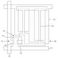
도 1을 참조하면, IPS 모드 액정 표시소자는 데이터라인(52)과 게이트라인(54)의 교차부에 TFT(50)가 형성되며, 데이터라인(52)과 게이트라인(54) 사이의 화소영역에 화소전극들(48)이 매트릭스 형태로 배치된다. TFT(50)는 도 2와 같이 배면기판(32) 상에 형성된다. 이 TFT(50)는 게이트라인(54)에 접속된 게이트전극(34), 데이터라인(52)에 접속된 소오스전극(42) 및 화소전극(48)에 접속된 드레인전극(44)을 포함한다. 배면기판(32)에는 크롬(Cr) 등의 금속을 증착하고 패터닝하여 게이트전극(34) 및 공통전극(35)이 형성된다. 여기서, 공통전극(35)은 화소셀 영역 내에서 세 열의 스트라입 형태로 패터닝된다. 게이트전극(34) 및 공통전극(35)이 형성된 배면기판(2) 상에는 SiNx 등의 무기 유전체로 된 게이트절연막(36)이 전면 증착된다. 이 게이트절연막(36) 위에는 a-Si으로 된 반도체층(38)과 a-Si에 n+ 이온이 도핑된 오믹접촉층(40)이 게이트전극(34) 상의 게이트절연막(36)을 덮게끔 순차적으로 형성된다. 오믹접촉층(40) 위에는 금속으로 된 소오스전극(42)과 드레인전극(44)이 형성된다. 소오스전극(42)과 드레인전극(44)은 미리 설정된 채널폭만큼 이격되게 패터닝된다. 그리고 인듐 틴 옥사이드(Indium Tin Oxide)가 드레인전극(16)과 게이트절연막(36) 상에 증착된 후 패터닝됨으로써 화소전극(48)이 형성된다. 여기서, 화소전극(48)은 드레인전극(44)에 접속되며 화소셀 영역 내에서 공통전극(35)과 교번되도록 두 열의 스트라입 형태로 패터닝된다. 이어서, 소오스전극(42)과 드레인전극(44) 사이에 형성된 채널을 따라 오믹접촉층(40)이 에칭되어 반도체층(38)을 노출시키게 된다. 그리고 SiNx, SiOx 등으로 된 보호막(46)이 배면기판(32) 상에 전면 증착되어 TFT(50)를 덮게 된다.Referring to FIG. 1, in the IPS mode liquid crystal display, a
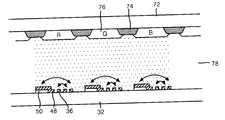
이와 같이 TFT 어레이가 형성된 배면기판(32)은 도 3과 같이 액정층(78)을 사이에 두고 블랙 매트릭스(74)와 컬러필터(76)가 형성된 전면기판(72)과 대면된다. TFT의 게이트전극(34)에 게이트하이펄스가 인가되어 소오스전극(42)과 드레인전극(44) 사이에 채널이 형성되는 스캐닝 기간동안, 수평방향으로 대향된 화소전극(48)과 공통전극(35) 사이에 비디오 데이터전압과 공통전압의 차전압에 해당하는 전계가 인가된다. 이 수직전계에 의해 액정층(78)의 액정들이 구동됨으로써 백라잇으로부터 입사되는 광의 광량을 조절하게 된다.As described above, the
이를 도 4와 결부하여 설명하면, TFT 어레이(90)이가 형성된 배면기판(32) 상에는 외부 구동부에서 생성된 공통전압을 공통전극(35)으로 인가하기 위한 다수의 공통전압라인(87)이 형성된다. 또한, 배면기판(32) 상에는 외부 구동부에서 생성된 게이트전압을 게이트전극(34)으로 인가하기 위한 다수의 게이트라인(85)이 공통전압라인(87)에 나란하게 형성된다. 공통전압라인(87)은 외부 드라이버 집적회로 라인과 접속되기 위한 공통전압패드(80)와 접속된다. 게이트라인(85)은 외부 드라이버 집적회로 라인과 접속되기 위한 다수의 게이트링크(86) 및 게이트패드(84)와 접속된다. 게이트링크(86)는 TFT 어레이(90)의 외부에 형성되어 게이트라인(85)과 게이트패드(84)를 상호 접속하여 외부 드라이버 집적회로부에서 전송된 게이트전압을 TFT 어레이(90)로 전송한다. 또한, 비디오 데이터전압을 TFT 어레이(90)로 전송하기 위한 다수의 데이터패드(82) 및 데이터라인(83)이 배면기판(32) 상에 형성된다. 이렇게 형성된 배면기판(32)과 블랙 매트릭스(74)와 컬러필터(76)가 형성된 전면기판(72)을 상호 대면되게 합착한 후, 그 사이에 액정(93)이 주입된다. 이때, 배면기판(32)과 전면기판(72) 사이에 주입되는 액정(93)은 TFT 어레이(90) 영역, 게이트패드(84) 및 게이트링크(86) 영역에도 주입된다. 이렇게 주입되는 액정(93)중 "A"와 같이, 게이트링크(87) 영역에 주입된 액정(93)은 게이트링크(86)로 인가되는 게이트전압과 공통전압라인(87)으로 인가되는 공통전압이 직접 인가되어 액정열화가 발생하게 된다.Referring to FIG. 4, a plurality of
이를 상세히 하면, TFT 어레이(90) 영역에 마련된 TFT의 게이트전극(34)에 게이트전압이 인가되어 소오스전극(42)과 드레인전극(44) 사이에 채널이 형성되는 스캐닝 기간동안, 수평방향으로 대향된 화소전극(48)과 공통전극(35) 사이에 비디 오 데이터전압과 공통전압의 차전압에 해당하는 전계가 인가된다. 이 수직전계에 의해 액정층(78)의 액정들이 구동됨으로써 백라잇으로부터 입사되는 광의 광량을 조절하게 된다. 그러나, 게이트링크(86) 및 공통전압라인(87)이 교차되도록 형성된 TFT 어레이(90) 외곽부에 주입된 액정(93)에는 공통전압라인(87)에 인가되는 공통전압(통상, 5V)과 게이트링크(86)로 인가되는 게이트전압(통상, 게이트하이전압은 +20V, 게이트로우전압은 -5V)이 동시에 인가된다. 이때, 공통전압과 게이트로우전압을 합한 전압이 TFT 어레이(90)에 주입된 액정(93)에 가해지게 된다. 여기서, 게이트전압중 게이트로우전압만을 언급한 이유는 게이트로우전압 파형의 폭이 게이트하이전압 파형의 폭에 비해 크기 때문이다. 즉, 액정(93)에 인가되는 게이트하이전압의 타이밍기간보다 게이트노우전압의 타이밍기간이 더 길기 때문에 한 프레임당 액정(93)에 인가되는 게이트전압중에서 게이트노우전압이 대부분의 타이밍기간을 차지하게 된다. 이로 인해, TFT 어레이(90) 외곽부에 주입된 액정(93)에는 10V의 전압이 인가되게 된다. 이 전압에 의해 TFT 어레이(90) 외곽부의 액정(93)에 열화가 발생하게 됨과 아울러 이 액정열화로 인해 액정열화가 발생한 부근에 위치한 TFT 어레이(90) 영역의 액정(93)까지 액정열화가 확산되어 그 부분에 얼룩이 발생된다. 이와 아울러, TFT 어레이(90)의 구동을 지속할 경우나 고온 동작등의 환경변화에 따라 액정열화가 TFT 어레이(90) 영역의 내부로 확산되어 표시품위 및 신뢰성 문제를 유발한다. In detail, during the scanning period in which a gate voltage is applied to the
또한, 다수의 공통전압라인(87)중 공통전압패드(80)와 직접 접속되는 공통전압라인(87)의 거리가 크기 때문에 TFT 어레이(90)의 상단으로 인가되는 공통전압과 TFT 어레이(90)의 하단으로 인가되는 공통전압간에 시간지연이 발생하게 되어 액정 표시소자의 구동이 제대로 이루어지지 않는다.In addition, the common voltage applied to the upper end of the TFT array 90 and the TFT array 90 because the distance of the
따라서, 본 발명의 목적은 IPS 모드에 있어서, TFT 어레이 외곽부에 발생되는 얼룩을 제거하기 위한 액정 표시소자를 제공함에 있다.Accordingly, an object of the present invention is to provide a liquid crystal display for removing spots generated in the outer portion of the TFT array in the IPS mode.
본 발명의 다른 목적은 TFT 어레이 영역으로 인가되는 공통전압의 시간지연을 최소화하기 위한 액정 표시소자를 제공함에 있다.
Another object of the present invention is to provide a liquid crystal display device for minimizing time delay of a common voltage applied to a TFT array region.
상기 목적을 달성하기 위하여 본 발명의 실시예에 따른 액정 표시소자는 표시부를 구동하기 위한 박막트랜지스터 어레이가 형성된 인 플레인 스위치모드의 액정 표시소자에 있어서, 상기 박막트랜지스터 어레이에 비디오 데이터신호를 인가하기 위한 다수의 데이터라인과; 상기 박막트랜지스터 어레이에 구동전압을 인가하기 위한 다수의 게이트라인과; 상기 박막 트랜지스터 어레이에 공통전압을 인가하기 위한 다수의 공통전압라인들과: 상기 다수의 공통전압라인들 중 상기 박막 트랜지스터 어레이 외부에 형성된 공통전압라인은 상기 박막 트랜지스터 어레이와 1~1.5mm 정도의 이격을 두고 형성된 것을 특징으로 한다.
상기 박막 트랜지스터 어레이 외부 중 게이트 링크 영역에 형성된 공통전압라인이 상기 박막 트랜지스터 어레이와 1~1.5mm 정도의 이격을 두고 형성된 것을 특징으로 한다.
상기 공통전압라인은 상기 박막트랜지스터 어레이의 좌/우측에 상기 데이터라인과 나란하게 형성되는 제 1 공통전압라인과; 상기 제 1 공통전압라인에서 분기하여 상기 게이트라인과 나란하게 형성되는 제 2 공통전압라인과; 상기 게이트라인과 접속되는 게이트링크와 나란하게 형성되어 상기 제 1 공통전압라인과 접속되는 제 3 공통전압라인을 특징으로 한다.
본 발명은 표시부를 구동하기 위한 박막트랜지스터 어레이가 형성된 인 플레인 스위치모드의 액정 표시소자에 있어서, 상기 박막트랜지스터 어레이에 비디오 데이터신호를 인가하기 위한 다수의 데이터라인과; 상기 박막트랜지스터 어레이에 구동전압을 인가하기 위한 다수의 게이트라인과; 상기 박막트랜지스터 어레이 영역에 공통전압을 인가하기 위한 다수의 공통전압라인과; 상기 박막 트랜지스터 어레이 외부영역에서 상기 공통전압라인의 양측에 나란하게 형성되는 더미신호라인을 구비하고, 상기 더미신호라인에는 상기 데이터신호와 같이 프레임마다 극성이 인버젼되는 교류신호가 인가되는 것을 특징으로 한다.
상기 공통전압라인은 상기 박막트랜지스터 어레이의 좌/우측에 상기 데이터라인과 나란하게 형성되는 제 1 공통전압라인과; 상기 게이트라인과 접속되는 게이트링크와 나란하게 형성되어 상기 제 1 공통전압라인과 접속되는 제 2 공통전압라인인 것을 특징으로 한다.
상기 공통전압라인에 외부 구동회로로부터의 공통신호를 공급하기 위한 다수개의 공통전압패드와; 상기 게이트 라인에 외부 구동회로로부터의 구동신호를 공급하기 위한 다수개의 게이트패드와; 상기 데이터 라인에 외부 구동회로로부터의 데이터신호를 공급하기 위한 다수개의 데이터패드를 더 구비한다.
상기 공통전압패드는 데이터 패드가 형성되는 데이터 패드영역 및 상기 게이트패드가 형성되는 게이트 패드영역에 형성된다.
상기 더미신호라인에 외부구동회로로부터 교류신호를 공급하기 위한 다수개의 더미신호패드를 더 구비하며, 상기 더미신호패드는 상기 데이터 패드영역 및 게이트 패드영역에 형성된다.In order to achieve the above object, a liquid crystal display device according to an exemplary embodiment of the present invention is a liquid crystal display device in an in-plane switch mode in which a thin film transistor array for driving a display unit is provided. A plurality of data lines; A plurality of gate lines for applying a driving voltage to the thin film transistor array; A plurality of common voltage lines for applying a common voltage to the thin film transistor array: a common voltage line formed outside the thin film transistor array among the plurality of common voltage lines is separated from the thin film transistor array by about 1 to 1.5 mm Characterized in that formed.
The common voltage line formed in the gate link region of the thin film transistor array is spaced apart from the thin film transistor array by about 1 to 1.5 mm.
The common voltage line may include a first common voltage line formed on the left and right sides of the thin film transistor array in parallel with the data line; A second common voltage line branched from the first common voltage line to be parallel to the gate line; And a third common voltage line formed to be parallel to the gate link connected to the gate line and connected to the first common voltage line.
An in-plane switch mode liquid crystal display device having a thin film transistor array for driving a display unit, comprising: a plurality of data lines for applying a video data signal to the thin film transistor array; A plurality of gate lines for applying a driving voltage to the thin film transistor array; A plurality of common voltage lines for applying a common voltage to the thin film transistor array region; And a dummy signal line formed on both sides of the common voltage line in an external region of the thin film transistor array, and an alternating current signal having a polarity inverted for each frame is applied to the dummy signal line like the data signal. do.
The common voltage line may include a first common voltage line formed on the left and right sides of the thin film transistor array in parallel with the data line; And a second common voltage line formed parallel to the gate link connected to the gate line and connected to the first common voltage line.
A plurality of common voltage pads for supplying a common signal from an external driving circuit to the common voltage line; A plurality of gate pads for supplying a driving signal from an external driving circuit to the gate line; The data line further includes a plurality of data pads for supplying data signals from an external driving circuit.
The common voltage pad is formed in a data pad region where a data pad is formed and a gate pad region where the gate pad is formed.
The dummy signal line further includes a plurality of dummy signal pads for supplying an AC signal from an external driving circuit, wherein the dummy signal pads are formed in the data pad area and the gate pad area.
삭제delete
상기 목적 외에 본 발명의 다른 목적 및 특징들은 첨부도면을 참조한 실시예에 대한 설명을 통하여 명백하게 드러나게 될 것이다.Other objects and features of the present invention in addition to the above objects will become apparent from the description of the embodiments with reference to the accompanying drawings.
도 5는 본 발명의 제 1 실시예에 따른 액정 표시소자의 구동회로를 간략하게 도시한 평면도.5 is a plan view briefly showing a driving circuit of a liquid crystal display device according to a first embodiment of the present invention;
도 5를 참조하면, 우선, 본 발명의 제 1 실시예에 따른 액정 표시소자의 구동회로는 배면기판(100) 상에 화상을 표시하기 위한 TFT 어레이(108)와, 외부 구동부에서 생성된 공통전압을 TFT 어레이(108)쪽으로 인가하기 위한 다수의 공통전압패드(102) 및 공통전압라인(112)과 다수의 게이트패드(106) 및 게이트라인(115)을 구비한다. 공통전압라인(112)은 TFT 어레이(108)와 1∼1.5mm이상의 이격거리(L)를 두고 TFT 어레이(108) 외곽부에 형성된다. 또한, TFT 어레이(108) 영역내에 게이트라인(115)과 나란한 방향으로 형성된다. 게이트패드(106)와 게이트라인(115)은 게이트링크(110)에 의해 상호 연결된다.Referring to FIG. 5, first, the driving circuit of the liquid crystal display according to the first embodiment of the present invention includes a
이와 같이 TFT 어레이(108) 외곽부에 TFT 어레이(108)와 1∼1.5mm이상의 이격거리(L)를 두고 공통전압라인(112)을 형성함으로써, 그 부분에 주입된 액정(113)으로 게이트전압과 공통전압의 합전압이 가해져 액정열화가 발생하더라도 액정열화가 TFT 어레이(108) 영역으로 확산되지 않는다.As such, the
도 6은 본 발명의 제 2 실시예에 따른 액정 표시소자의 구동회로를 간략하게 도시한 평면도이다.6 is a plan view briefly illustrating a driving circuit of a liquid crystal display according to a second exemplary embodiment of the present invention.
도 6을 참조하면, 우선 본 발명의 제 2 실시예에 따른 액정 표시소자의 구동회로는 배면기판(120) 상에 화상을 표시하기 위한 TFT 어레이(127)와, 외부 구동부에서 생성된 공통전압을 TFT 어레이(127)쪽으로 인가하기 위한 다수의 공통전압패드(122) 및 공통전압라인(128)과 다수의 게이트패드(126) 및 게이트라인(132)과; TFT 어레이(127)의 외곽부에 형성되는 공통전압라인(128) 양측으로 공통전압라인(128)과 나란하게 형성되는 더미신호라인(138)을 구비한다. 이와 아울러, 공통전압라인(128)은 TFT 어레이(127) 영역에 게이트라인(132)과 나란한 방향으로 형성된다. 더미신호라인(138)은 데이터드라이버 집적회로(도시되지 않음)에 인가되는 비디오 데이터신호를 전송하기 위해 더미패드(136)와 접속된다.Referring to FIG. 6, first, a driving circuit of a liquid crystal display according to a second exemplary embodiment of the present invention uses a
이와 같이 TFT 어레이(127) 외곽부, 즉 TFT 어레이(127)와 게이트패드(126) 사이와 TFT 어레이(127)의 우측 외곽부(이하 "TFT 어레이 외곽부)에 형성된 공통전압라인(128)의 양측에 공통전압라인(128)과 나란하게 더미신호라인(138)을 형성함으로써, 그 부분에 주입된 액정(133)으로 인가되는 전압들이 TFT 어레이(127) 영역에 인가되는 전압들과 동일하게 하여 TFT 어레이(127) 영역의 액정(133)처럼 인버젼(inversion)하여 구동시켜준다. 즉, 게이트로우전압 및 공통전압이 가해지는 TFT 어레이(127) 외곽부의 액정(133)에 비디오 데이터신호인 더미신호를 인가하여 TFT 어레이(127) 외곽부에 주입된 액정(133)이 TFT 어레이(127) 영역내의 액정(133)과 동일하게 인버젼하도록 한다. 이렇게 함으로써, TFT 어레이(127) 외곽부에 주입된 액정(133)에 게이트전압과 공통전압으로 구성된 직류전압이 직접 가 해지지 않게 되어 액정열화가 발생하지 않는다.As such, the
도 7은 본 발명의 제 3 실시예에 따른 액정 표시소자의 구동회로를 간략하게 도시한 평면도이다.7 is a plan view briefly illustrating a driving circuit of a liquid crystal display according to a third exemplary embodiment of the present invention.
도 7을 참조하면, 우선 본 발명의 제 3 실시예에 따른 액정 표시소자는 도 6에 도시된 본 발명의 제 2 실시예와 동일한 구동특성을 보인다. 단지, TFT 어레이 영역으로 인가되는 공통전압의 시간지연을 최소화하기 위해 다수의 데이터패드(146)영역에 마련된 다수의 제 1 공통전압패드(142)쪽에서만 인가된 공통전압을 게이트패드(155) 쪽에서도 인가하도록 게이트패드(155) 영역에 다수의 제 2 공통전압패드(143)를 구비한다. 제 2 공통전압패드(143)는 다수의 게이트패드(150)중 소정의 게이트패드들(155)을 한 묶음(예를 들면 10개의 게이트패드를 한 묶음)으로 하여 그 묶음들 사이에 형성된다. 이렇게 형성된 제 2 공통전압패드(143)는 제 1 공통전압패드(142)에서 신장된 제1 공통전압라인(150)과 접속되기 위해 제 2 공통전압라인(151)과 접속된다. 제 1 공통전압라인(150)과 제 2 공통전압라인(151)의 양측에는 본 발명의 제 2 실시예와 마찬가지로 더미신호라인(144)들이 제1 공통전압라인(150) 및 제 2 공통전압라인(151)과 나란한 방향으로 형성된다.Referring to FIG. 7, first, the liquid crystal display according to the third exemplary embodiment of the present invention exhibits the same driving characteristics as the second exemplary embodiment of the present invention illustrated in FIG. 6. However, in order to minimize the time delay of the common voltage applied to the TFT array region, the common voltage applied only on the side of the plurality of first common voltage pads 142 provided in the plurality of
이와 같이 TFT 어레이(140) 외곽부, 즉 TFT 어레이(140)와 게이트패드(150) 사이와 TFT 어레이(140)의 우측 외곽부(이하 "TFT 어레이 외곽부)에 형성된 제 1 및 제 2 공통전압라인(150,151)의 양측에 제 1 및 제 2 공통전압라인(150,151)과 나란하게 더미신호라인(144)을 형성함으로써, 그 부분에 주입된 액정(148)으로 인 가되는 전압들이 TFT 어레이(140) 영역에 인가되는 전압들과 동일하게 하여 TFT 어레이(140) 영역의 액정(148)처럼 인버젼(inversion)하여 구동시켜준다. 즉, 게이트로우전압 및 공통전압이 가해지는 TFT 어레이(140) 외곽부의 액정(148)에 비디오 데이터신호인 더미신호를 인가하여 TFT 어레이(140) 외곽부에 주입된 액정(148)이 TFT 어레이(140) 영역내의 액정(148)과 동일하게 인버젼하도록 한다. 이렇게 함으로써, TFT 어레이(140) 외곽부에 주입된 액정(148)에 게이트전압과 공통전압으로 구성된 직류전압이 직접 가해지지 않게 되어 액정열화가 발생하지 않는다.As such, the first and second common voltages formed outside the
이와 같이 본 발명의 실시예에 따른 액정 표시소자의 구동회로는 TFT 어레이 외곽부에 주입된 액정의 열화를 방지하기 위해 그 부분에 형성된 공통전압라인들을 TFT 어레이와 1∼1.5mm정도의 이격거리를 두고 형성한다. 또한, TFT 어레이 외곽부에 형성된 공통전압라인의 양측에 더미신호라인을 형성하여 그 더미신호라인을 통해 비디오 데이터신호를 전송하여 TFT 어레이 영역에서와 동일하게 TFT 어레이 외곽부에 주입된 액정이 인버젼되도록 한다. 이와 아울러, TFT 어레이 영역으로 인가되는 공통전압의 시간지연을 최소화하기 위해 데이터패드 영역쪽에서만 인가된 공통전압을 게이트패드 영역쪽에서도 인가되도록 하기 위해 게이트패드 쪽에 공통전압패드를 형성하고 그 공통전압패드와 데이터패드 영역으로부터 신장된 공통전압라인을 접속하기 위한 공통전압라인을 소정의 게이트패드마다 형성한다.As described above, the driving circuit of the liquid crystal display according to the exemplary embodiment of the present invention has a common voltage line formed at a portion of the liquid crystal display device at a distance of about 1 to 1.5 mm from the TFT array to prevent deterioration of the liquid crystal injected into the TFT array. Leave and form. In addition, dummy signal lines are formed on both sides of the common voltage line formed in the TFT array outer part, and video data signals are transmitted through the dummy signal line, thereby injecting liquid crystals injected into the TFT array outer part as in the TFT array area. Be sure to In addition, in order to minimize the time delay of the common voltage applied to the TFT array region, a common voltage pad is formed on the gate pad side so that the common voltage applied only on the data pad region side is also applied to the gate pad region, A common voltage line for connecting the common voltage line extending from the data pad region is formed for each predetermined gate pad.
상술한 바와 같이, 본 발명의 실시예에 따른 액정 표시소자는 TFT 어레이 외 곽부에 공통전압라인을 TFT 어레이 영역과 1∼1.5mm정도의 이격을 두고 형성함과 아울러 공통전압라인의 양측에 비디오 데이터신호를 인가하기 위한 더미신호라인을 형성함으로써, TFT 어레이 외곽부에 주입된 액정에 발생하는 열화가 TFT 어레이 영역까지 확산되지 않도록 하거나 TFT 어레이 외곽부에 주입된 액정이 TFT 어레이 영역내의 액정과 동일하게 인버젼하도록 TFT 어레이 외곽부에 주입된 액정에 비디오 데이터신호를 인가한다. 이로 인해, 액정의 열화를 방지함과 아울러 더 나아가 화소영역 외곽부에 형성되는 얼룩을 최소화할 수 있다.As described above, the liquid crystal display according to the exemplary embodiment of the present invention forms a common voltage line on the outer side of the TFT array at a distance of about 1 to 1.5 mm from the TFT array region, and the video data on both sides of the common voltage line. By forming a dummy signal line for applying a signal, it is possible to prevent the deterioration occurring in the liquid crystal injected into the TFT array outer portion from spreading to the TFT array region or that the liquid crystal injected into the TFT array outer portion is the same as the liquid crystal in the TFT array region. The video data signal is applied to the liquid crystal injected to the TFT array outer portion to invert. As a result, it is possible to prevent deterioration of the liquid crystal and further to minimize spots formed on the outer portion of the pixel region.
이상 설명한 내용을 통해 당업자라면 본 발명의 기술사상을 일탈하지 아니하는 범위에서 다양한 변경 및 수정이 가능함을 알 수 있을 것이다. 따라서, 본 발명의 기술적 범위는 명세서의 상세한 설명에 기재된 내용으로 한정되는 것이 아니라 특허 청구의 범위에 의해 정하여 져야만 할 것이다.Those skilled in the art will appreciate that various changes and modifications can be made without departing from the technical spirit of the present invention. Therefore, the technical scope of the present invention should not be limited to the contents described in the detailed description of the specification but should be defined by the claims.
Claims (9)
Translated fromKoreanPriority Applications (2)
| Application Number | Priority Date | Filing Date | Title |
|---|---|---|---|
| KR1020000060821AKR100604271B1 (en) | 2000-10-16 | 2000-10-16 | Liquid crystal display |
| US09/892,883US6864937B2 (en) | 2000-10-16 | 2001-06-28 | In-plane switching mode liquid crystal display device with peripheral circuit lines for shielding |
Applications Claiming Priority (1)
| Application Number | Priority Date | Filing Date | Title |
|---|---|---|---|
| KR1020000060821AKR100604271B1 (en) | 2000-10-16 | 2000-10-16 | Liquid crystal display |
Publications (2)
| Publication Number | Publication Date |
|---|---|
| KR20020030227A KR20020030227A (en) | 2002-04-24 |
| KR100604271B1true KR100604271B1 (en) | 2006-07-24 |
Family
ID=19693755
Family Applications (1)
| Application Number | Title | Priority Date | Filing Date |
|---|---|---|---|
| KR1020000060821AExpired - Fee RelatedKR100604271B1 (en) | 2000-10-16 | 2000-10-16 | Liquid crystal display |
Country Status (2)
| Country | Link |
|---|---|
| US (1) | US6864937B2 (en) |
| KR (1) | KR100604271B1 (en) |
Cited By (1)
| Publication number | Priority date | Publication date | Assignee | Title |
|---|---|---|---|---|
| US7985954B2 (en) | 2008-08-29 | 2011-07-26 | Samsung Electronics Co., Ltd. | X-ray detection panel and X-ray detector |
Families Citing this family (25)
| Publication number | Priority date | Publication date | Assignee | Title |
|---|---|---|---|---|
| KR100587366B1 (en)* | 2000-08-30 | 2006-06-08 | 엘지.필립스 엘시디 주식회사 | Transverse electric field liquid crystal display device and manufacturing method thereof |
| KR100640992B1 (en)* | 2001-05-25 | 2006-11-06 | 엘지.필립스 엘시디 주식회사 | LCD and its manufacturing method |
| KR100760946B1 (en)* | 2002-08-17 | 2007-09-21 | 엘지.필립스 엘시디 주식회사 | Transverse electric field type liquid crystal display device and manufacturing method thereof |
| US6970223B2 (en)* | 2002-08-17 | 2005-11-29 | Lg. Philips Lcd Co., Ltd. | In-plane switching mode LCD device and method for fabricating the same |
| KR100878790B1 (en)* | 2002-09-05 | 2009-01-14 | 삼성전자주식회사 | Active matrix image display device and image display method using same |
| JP3980462B2 (en)* | 2002-10-30 | 2007-09-26 | 株式会社 日立ディスプレイズ | Image display device |
| US7602465B2 (en)* | 2002-10-31 | 2009-10-13 | Lg Display Co., Ltd. | In-plane switching mode liquid crystal display device |
| KR100920344B1 (en)* | 2002-12-03 | 2009-10-07 | 삼성전자주식회사 | Thin film transistor array panel for liquid crystal display |
| KR100487358B1 (en)* | 2002-12-10 | 2005-05-03 | 엘지.필립스 엘시디 주식회사 | Liquid crystal display panel of line on glass type and method of fabricating the same |
| KR100912697B1 (en)* | 2003-02-26 | 2009-08-19 | 엘지디스플레이 주식회사 | Liquid crystal display |
| JP2004294787A (en)* | 2003-03-27 | 2004-10-21 | Sharp Corp | Display device and wiring repair method thereof |
| KR100710164B1 (en)* | 2003-12-30 | 2007-04-20 | 엘지.필립스 엘시디 주식회사 | Transverse electric field liquid crystal display device |
| US8035588B2 (en)* | 2004-03-03 | 2011-10-11 | Hannstar Display Corp. | Liquid crystal display panel with auxiliary line disposed between boundary data line and pixel electrode and driving method thereof |
| TWI258048B (en)* | 2004-06-15 | 2006-07-11 | Taiwan Tft Lcd Ass | Structure of TFT electrode for preventing metal layer diffusion and manufacturing method thereof |
| KR20060082517A (en)* | 2005-01-12 | 2006-07-19 | 삼성전자주식회사 | Thin film transistor substrate and inspection method |
| TWI298867B (en)* | 2005-01-21 | 2008-07-11 | Chi Mei Optoelectronics Corp | Liquid crystal display and driving method thereof |
| KR101177593B1 (en)* | 2005-12-29 | 2012-08-27 | 엘지디스플레이 주식회사 | Liquid crystal display device |
| US8139174B2 (en)* | 2006-01-10 | 2012-03-20 | Chimei Innolux Corporation | Display device for displaying images involving display pixels and non-display pixels |
| TWI375063B (en)* | 2008-09-04 | 2012-10-21 | Chunghwa Picture Tubes Ltd | Lcd panel |
| TWI380109B (en)* | 2009-01-23 | 2012-12-21 | Au Optronics Corp | Display device and method of equalizing loading effect of display device |
| KR101455312B1 (en)* | 2012-06-21 | 2014-10-27 | 엘지디스플레이 주식회사 | A Patterned Retarder Type Stereoscopic Image Display Device and Method for Manufacturing The Same |
| KR102074424B1 (en)* | 2013-03-04 | 2020-02-07 | 삼성디스플레이 주식회사 | Liquid crystal display and manufacturing method thereof |
| JP6475947B2 (en)* | 2014-09-30 | 2019-02-27 | 株式会社ジャパンディスプレイ | Liquid crystal display |
| KR20240114822A (en)* | 2023-01-17 | 2024-07-25 | 삼성디스플레이 주식회사 | Display device |
| CN119024607A (en)* | 2023-05-25 | 2024-11-26 | 京东方科技集团股份有限公司 | Array substrate and preparation method thereof, and display device |
Citations (2)
| Publication number | Priority date | Publication date | Assignee | Title |
|---|---|---|---|---|
| JPH08262408A (en)* | 1995-03-06 | 1996-10-11 | Thomson Multimedia Sa | Video display device |
| JPH11271722A (en)* | 1998-03-20 | 1999-10-08 | Sharp Corp | Active matrix substrate and inspection method thereof |
Family Cites Families (9)
| Publication number | Priority date | Publication date | Assignee | Title |
|---|---|---|---|---|
| JPS5840728B2 (en)* | 1978-08-23 | 1983-09-07 | 株式会社日立製作所 | liquid crystal display device |
| US5151689A (en)* | 1988-04-25 | 1992-09-29 | Hitachi, Ltd. | Display device with matrix-arranged pixels having reduced number of vertical signal lines |
| JP3328944B2 (en)* | 1991-10-09 | 2002-09-30 | セイコーエプソン株式会社 | Driving method of liquid crystal display device |
| EP0588568B1 (en) | 1992-09-18 | 2002-12-18 | Hitachi, Ltd. | A liquid crystal display device |
| JPH07177444A (en)* | 1993-12-21 | 1995-07-14 | Canon Inc | Image display device |
| JP3727416B2 (en)* | 1996-05-31 | 2005-12-14 | 株式会社半導体エネルギー研究所 | Display device |
| US20010055074A1 (en)* | 1997-07-22 | 2001-12-27 | Hiroshi Komatsu | In-plane switching mode lcd with specific arrangement of common bus line, data electrode, and common electrode |
| US6693684B2 (en)* | 1999-09-15 | 2004-02-17 | Rainbow Displays, Inc. | Construction of large, robust, monolithic and monolithic-like, AMLCD displays with wide view angle |
| KR100604270B1 (en)* | 2000-09-19 | 2006-07-24 | 엘지.필립스 엘시디 주식회사 | Liquid crystal display |
- 2000
- 2000-10-16KRKR1020000060821Apatent/KR100604271B1/ennot_activeExpired - Fee Related
- 2001
- 2001-06-28USUS09/892,883patent/US6864937B2/ennot_activeExpired - Lifetime
Patent Citations (2)
| Publication number | Priority date | Publication date | Assignee | Title |
|---|---|---|---|---|
| JPH08262408A (en)* | 1995-03-06 | 1996-10-11 | Thomson Multimedia Sa | Video display device |
| JPH11271722A (en)* | 1998-03-20 | 1999-10-08 | Sharp Corp | Active matrix substrate and inspection method thereof |
Cited By (1)
| Publication number | Priority date | Publication date | Assignee | Title |
|---|---|---|---|---|
| US7985954B2 (en) | 2008-08-29 | 2011-07-26 | Samsung Electronics Co., Ltd. | X-ray detection panel and X-ray detector |
Also Published As
| Publication number | Publication date |
|---|---|
| US20020044246A1 (en) | 2002-04-18 |
| US6864937B2 (en) | 2005-03-08 |
| KR20020030227A (en) | 2002-04-24 |
Similar Documents
| Publication | Publication Date | Title |
|---|---|---|
| KR100604271B1 (en) | Liquid crystal display | |
| US9541808B2 (en) | Liquid crystal display device | |
| KR100611856B1 (en) | Liquid crystal device, method for driving the same, and electronic apparatus | |
| KR100504569B1 (en) | Liquid Crystal Display Device with Electrode on Barrier Rib And Fabricating Method Thereof | |
| KR100236892B1 (en) | Color filter, liquid crystal display panel, liquid crystal display device and manufacturing method thereof | |
| JP2734444B2 (en) | Liquid crystal display | |
| KR100882699B1 (en) | LCD and its driving method | |
| US7800570B2 (en) | LCD device capable of controlling a viewing angle and method for driving the same | |
| KR20050068267A (en) | In-plane switching mode liquid crystal display device | |
| CN108957874B (en) | Liquid crystal display device and driving method thereof | |
| KR100604270B1 (en) | Liquid crystal display | |
| US6590550B2 (en) | Liquid crystal display device having stabilized pixel electrode potentials | |
| JP3031295B2 (en) | Active matrix type liquid crystal display | |
| KR20020009144A (en) | liquid crystal display device | |
| JPH10319428A (en) | Active matrix type liquid crystal display | |
| JPH10213816A (en) | Active matrix type liquid crystal display | |
| KR100494694B1 (en) | Apparatus for thin film transistor liquid crystal display | |
| US20120086685A1 (en) | Thin film transtistor array panel and liquid crystal display | |
| KR100965582B1 (en) | Antistatic circuit of liquid crystal display | |
| KR100529572B1 (en) | Thin film transistor liquid crystal display | |
| KR101023718B1 (en) | LCD and its manufacturing method | |
| KR101034744B1 (en) | Thin film transistor structure of liquid crystal display device | |
| JP2003177424A (en) | Liquid crystal display | |
| KR20060029101A (en) | Thin film transistor array substrate | |
| KR20080048872A (en) | LCD display device |
Legal Events
| Date | Code | Title | Description |
|---|---|---|---|
| PA0109 | Patent application | St.27 status event code:A-0-1-A10-A12-nap-PA0109 | |
| PN2301 | Change of applicant | St.27 status event code:A-3-3-R10-R13-asn-PN2301 St.27 status event code:A-3-3-R10-R11-asn-PN2301 | |
| PG1501 | Laying open of application | St.27 status event code:A-1-1-Q10-Q12-nap-PG1501 | |
| A201 | Request for examination | ||
| P11-X000 | Amendment of application requested | St.27 status event code:A-2-2-P10-P11-nap-X000 | |
| P13-X000 | Application amended | St.27 status event code:A-2-2-P10-P13-nap-X000 | |
| PA0201 | Request for examination | St.27 status event code:A-1-2-D10-D11-exm-PA0201 | |
| E902 | Notification of reason for refusal | ||
| PE0902 | Notice of grounds for rejection | St.27 status event code:A-1-2-D10-D21-exm-PE0902 | |
| E13-X000 | Pre-grant limitation requested | St.27 status event code:A-2-3-E10-E13-lim-X000 | |
| P11-X000 | Amendment of application requested | St.27 status event code:A-2-2-P10-P11-nap-X000 | |
| P13-X000 | Application amended | St.27 status event code:A-2-2-P10-P13-nap-X000 | |
| E701 | Decision to grant or registration of patent right | ||
| PE0701 | Decision of registration | St.27 status event code:A-1-2-D10-D22-exm-PE0701 | |
| GRNT | Written decision to grant | ||
| PR0701 | Registration of establishment | St.27 status event code:A-2-4-F10-F11-exm-PR0701 | |
| PR1002 | Payment of registration fee | St.27 status event code:A-2-2-U10-U11-oth-PR1002 Fee payment year number:1 | |
| PG1601 | Publication of registration | St.27 status event code:A-4-4-Q10-Q13-nap-PG1601 | |
| PN2301 | Change of applicant | St.27 status event code:A-5-5-R10-R13-asn-PN2301 St.27 status event code:A-5-5-R10-R11-asn-PN2301 | |
| PR1001 | Payment of annual fee | St.27 status event code:A-4-4-U10-U11-oth-PR1001 Fee payment year number:4 | |
| PR1001 | Payment of annual fee | St.27 status event code:A-4-4-U10-U11-oth-PR1001 Fee payment year number:5 | |
| R18-X000 | Changes to party contact information recorded | St.27 status event code:A-5-5-R10-R18-oth-X000 | |
| PR1001 | Payment of annual fee | St.27 status event code:A-4-4-U10-U11-oth-PR1001 Fee payment year number:6 | |
| R18-X000 | Changes to party contact information recorded | St.27 status event code:A-5-5-R10-R18-oth-X000 | |
| R18-X000 | Changes to party contact information recorded | St.27 status event code:A-5-5-R10-R18-oth-X000 | |
| PR1001 | Payment of annual fee | St.27 status event code:A-4-4-U10-U11-oth-PR1001 Fee payment year number:7 | |
| FPAY | Annual fee payment | Payment date:20130619 Year of fee payment:8 | |
| PR1001 | Payment of annual fee | St.27 status event code:A-4-4-U10-U11-oth-PR1001 Fee payment year number:8 | |
| FPAY | Annual fee payment | Payment date:20140630 Year of fee payment:9 | |
| PR1001 | Payment of annual fee | St.27 status event code:A-4-4-U10-U11-oth-PR1001 Fee payment year number:9 | |
| FPAY | Annual fee payment | Payment date:20150629 Year of fee payment:10 | |
| PR1001 | Payment of annual fee | St.27 status event code:A-4-4-U10-U11-oth-PR1001 Fee payment year number:10 | |
| FPAY | Annual fee payment | Payment date:20160630 Year of fee payment:11 | |
| PR1001 | Payment of annual fee | St.27 status event code:A-4-4-U10-U11-oth-PR1001 Fee payment year number:11 | |
| PR1001 | Payment of annual fee | St.27 status event code:A-4-4-U10-U11-oth-PR1001 Fee payment year number:12 | |
| PR1001 | Payment of annual fee | St.27 status event code:A-4-4-U10-U11-oth-PR1001 Fee payment year number:13 | |
| FPAY | Annual fee payment | Payment date:20190617 Year of fee payment:14 | |
| PR1001 | Payment of annual fee | St.27 status event code:A-4-4-U10-U11-oth-PR1001 Fee payment year number:14 | |
| PC1903 | Unpaid annual fee | St.27 status event code:A-4-4-U10-U13-oth-PC1903 Not in force date:20200719 Payment event data comment text:Termination Category : DEFAULT_OF_REGISTRATION_FEE | |
| PC1903 | Unpaid annual fee | St.27 status event code:N-4-6-H10-H13-oth-PC1903 Ip right cessation event data comment text:Termination Category : DEFAULT_OF_REGISTRATION_FEE Not in force date:20200719 |