KR100601694B1 - Waste toner collecting device, and electrophotographic image forming apparatus having same - Google Patents
Waste toner collecting device, and electrophotographic image forming apparatus having sameDownload PDFInfo
- Publication number
- KR100601694B1 KR100601694B1KR1020040056424AKR20040056424AKR100601694B1KR 100601694 B1KR100601694 B1KR 100601694B1KR 1020040056424 AKR1020040056424 AKR 1020040056424AKR 20040056424 AKR20040056424 AKR 20040056424AKR 100601694 B1KR100601694 B1KR 100601694B1
- Authority
- KR
- South Korea
- Prior art keywords
- waste toner
- photosensitive medium
- shaft
- collecting device
- passage
- Prior art date
- Legal status (The legal status is an assumption and is not a legal conclusion. Google has not performed a legal analysis and makes no representation as to the accuracy of the status listed.)
- Expired - Fee Related
Links
Images


Classifications
- G—PHYSICS
- G03—PHOTOGRAPHY; CINEMATOGRAPHY; ANALOGOUS TECHNIQUES USING WAVES OTHER THAN OPTICAL WAVES; ELECTROGRAPHY; HOLOGRAPHY
- G03G—ELECTROGRAPHY; ELECTROPHOTOGRAPHY; MAGNETOGRAPHY
- G03G21/00—Arrangements not provided for by groups G03G13/00 - G03G19/00, e.g. cleaning, elimination of residual charge
- G03G21/10—Collecting or recycling waste developer
- G03G21/12—Toner waste containers
- G—PHYSICS
- G03—PHOTOGRAPHY; CINEMATOGRAPHY; ANALOGOUS TECHNIQUES USING WAVES OTHER THAN OPTICAL WAVES; ELECTROGRAPHY; HOLOGRAPHY
- G03G—ELECTROGRAPHY; ELECTROPHOTOGRAPHY; MAGNETOGRAPHY
- G03G21/00—Arrangements not provided for by groups G03G13/00 - G03G19/00, e.g. cleaning, elimination of residual charge
- G03G21/10—Collecting or recycling waste developer
- G03G21/105—Arrangements for conveying toner waste
Landscapes
- Life Sciences & Earth Sciences (AREA)
- Engineering & Computer Science (AREA)
- Environmental & Geological Engineering (AREA)
- Sustainable Development (AREA)
- Physics & Mathematics (AREA)
- General Physics & Mathematics (AREA)
- Cleaning In Electrography (AREA)
Abstract
Translated fromKoreanDescription
Translated fromKorean도 1은 종래의 폐토너 수집장치를 포함하고 있는 현상유닛의 일 예를 도시한 단면도이다.1 is a cross-sectional view showing an example of a developing unit including a conventional waste toner collecting device.
도 2는 본 발명의 바람직한 실시예에 따른 전자사진방식 화상형성장치를 도시한 단면도이다.2 is a cross-sectional view showing an electrophotographic image forming apparatus according to a preferred embodiment of the present invention.
도 3은 본 발명의 제1 실시예에 따른 폐토너 수집장치를 포함하고 있는 현상유닛을 도시한 단면도이다.3 is a cross-sectional view showing a developing unit including a waste toner collecting device according to a first embodiment of the present invention.
도 4 및 도 5는 도 3의 현상유닛 내부의 폐토너 수집장치를 도시한 사시도 및 단면도이다.4 and 5 are a perspective view and a cross-sectional view showing a waste toner collecting device inside the developing unit of FIG.
도 6 및 도 7은 본 발명의 제2 실시예에 따른 폐토너 수집장치를 도시한 사시도 및 단면도이다.6 and 7 are a perspective view and a cross-sectional view showing a waste toner collecting device according to a second embodiment of the present invention.
도 8은 본 발명의 제2 실시예에 따른 폐토너 수집장치의 교란판을 왕복 회전시키는 구성을 도시한 도면이다.8 is a view showing a configuration for reciprocating the disturbing plate of the waste toner collecting device according to the second embodiment of the present invention.
<도면의 주요부분에 대한 부호의 설명><Description of the symbols for the main parts of the drawings>
100 ...전자사진방식 화상형성장치110 ...현상유닛100 ... Electrophotographic
114 ...감광매체115 ...현상롤러114 ...
120 ...대전롤러122 ...클리닝 블레이드120
125 ...교란판133 ...폐토너 컨테이너125 ... Jammer 133 ... Waste Toner Container
135 ...캠145 ...스프링135 ... Cam 145 ... Spring
150 ...반송벨트155 ...전사롤러150 ...
160 ...정착기165 ...광주사유닛160 ... Fuser 165 ... Optical scanning unit
본 발명은 전자사진방식 화상형성장치에 관한 것으로, 보다 상세하게는 감광매체로부터 폐토너를 떼어내 수용하는 폐토너 수집장치와, 이를 구비한 전자사진방식 화상형성장치에 관한 것이다.The present invention relates to an electrophotographic image forming apparatus, and more particularly, to a waste toner collecting apparatus for removing and containing waste toner from a photosensitive medium, and an electrophotographic image forming apparatus having the same.
일반적으로, 전자사진방식 화상형성장치란, 예컨데 레이저 프린터, 디지털 복사기 등과 같이, 소정 전위로 대전된 감광매체에 광을 주사하여 그 외주면에 정전잠상을 형성하고, 상기 정전잠상에 현상제(developing agent)인 토너를 투입하여 가시(可視)화상으로 현상한 후 이를 용지에 전사 및 정착시켜 화상을 인쇄하는 장치를 말한다. 이러한 전자사진방식 화상형성장치에는, 상기 가시화상을 용지에 전사할 때, 용지로 이동하지 못하고 감광매체에 그대로 잔류하는 폐토너를 상기 감광매체에서 제거하여 수용하는 폐토너 수집장치가 마련된다.In general, an electrophotographic image forming apparatus is, for example, a laser printer, a digital copier, etc., to scan light on a photosensitive medium charged to a predetermined potential to form an electrostatic latent image on its outer peripheral surface, and to develop a developer (deeloping agent) on the electrostatic latent image. It is a device that prints an image by inserting the toner and developing it into a visible image, then transferring and fixing the same on paper. The electrophotographic image forming apparatus is provided with a waste toner collecting device for removing and accommodating waste toner from the photosensitive medium when the visible image is transferred onto the paper and not being moved to the paper.
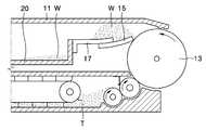
도 1은 종래의 폐토너 수집장치를 포함하고 있는 현상유닛의 일 예를 도시한 단면도이다.1 is a cross-sectional view showing an example of a developing unit including a conventional waste toner collecting device.
도 1을 참조하면, 현상제인 토너(T)가 수용된 현상유닛(10)의 하우징(11) 내부에 마련된 폐토너 수집장치는, 감광매체(13)의 외주면에 접하여 폐토너(W)를 긁어내는 클리닝 블레이드(15)와, 상기 클리닝 블레이드(15)를 지지하는 지지프레임(17)과, 클리닝 블레이드(15)에 의해 감광매체(13) 외주면에서 분리된 폐토너(W)가 모여 수용되는 폐토너 컨테이너(20)를 구비한다. 상기 하우징(11)의 내측면과 클리닝 블레이드(15) 및 지지프레임(17)은, 감광매체(13)에서 분리된 폐토너(W)를 폐토너 컨테이너(20)까지 인도하는 폐토너 통로를 형성한다.Referring to FIG. 1, the waste toner collecting device provided in the
그런데, 상기 종래의 폐토너 수집장치는, 클리닝 블레이드(15)에 의해 감광매체(13)에서 분리된 폐토너(W)가 상기 폐토너 통로를 따라 미끄러져 내리지 않고 클리닝 블레이드(15) 위에 쌓여, 폐토너(W)의 이동을 어렵게 하거나 심하면 폐토너 통로를 폐색하는 경우가 종종 발생하여 문제이다. 폐토너(W)의 이동이 원활치 못하여 감광매체(13) 주변 클리닝 블레이드(15) 위에 폐토너(W)가 쌓이게 되면, 상기 감광매체(13)의 원활한 회전을 방해하고, 그 외주면을 오염시켜 인쇄화상의 품질 저하를 야기하는 원인이 될 수 있다.However, in the conventional waste toner collecting device, the waste toner W separated from the
본 발명은 상기와 같은 문제점을 해결하기 위한 것으로, 폐토너 통로 내부에서 반복 운동하며 폐토너의 정체를 억제하는 수단을 구비하는 폐토너 수집장치와, 이를 구비한 전자사진방식 화상형성장치를 제공하는 것을 목적으로 한다.SUMMARY OF THE INVENTION The present invention has been made to solve the above problems, and provides a waste toner collecting device having a means for repetitively moving inside the waste toner passage and suppressing the waste toner, and an electrophotographic image forming apparatus having the same. For the purpose of
상기한 목적을 달성하기 위하여 본 발명은, 가시(可視)화상의 전사 과정에서 감광매체로부터 분리되지 못하고 그 외주면에 잔존한 폐토너를 긁어내 상기 감광매체로부터 분리하는 클리닝 블레이드;In order to achieve the above object, the present invention is a cleaning blade which separates from the photosensitive medium by scraping off the waste toner remaining on the outer circumferential surface without being separated from the photosensitive medium in the process of transferring the visible image;
상기 폐토너가 모여 수용되는 폐토너 컨테이너;A waste toner container in which the waste toner is collected and received;
상기 감광매체에서 분리된 폐토너를 폐토너 컨테이너까지 인도하는 폐토너 통로; 및A waste toner passage for guiding the waste toner separated from the photosensitive medium to the waste toner container; And
상기 폐토너 통로 내부에서 왕복운동하며 폐토너의 정체를 억제하는 교란판;을 구비하는 것을 특징으로 하는 폐토너 수집장치를 제공한다.And a disturbing plate configured to reciprocate in the waste toner passage and suppress the congestion of the waste toner.
바람직하게는, 상기 교란판은, 감광매체의 길이방향으로 연장되고 동(同) 방향으로 왕복운동하는 샤프트와, 상기 샤프트에 고정된 시트를 구비할 수 있다.Preferably, the disturbing plate may include a shaft extending in the longitudinal direction of the photosensitive medium and reciprocating in the same direction, and a sheet fixed to the shaft.
바람직하게는, 상기 폐토너 수집장치는, 상기 샤프트의 일단에 접하여 회전하는 경사면을 구비하는 캠과, 상기 샤프트를 캠을 향해 탄성 가압하는 스프링을 구비하여, 상기 캠이 회전함에 따라 샤프트가 감광매체의 길이방향으로 왕복운동하게 구성될 수 있다.Preferably, the waste toner collecting device includes a cam having an inclined surface that rotates in contact with one end of the shaft, and a spring that elastically presses the shaft toward the cam, so that the shaft rotates as the cam is rotated. It can be configured to reciprocate in the longitudinal direction of.
바람직하게는, 상기 시트에 폐토너의 통과가 용이하도록 통공이 형성될 수 있다.Preferably, a through hole may be formed in the sheet to facilitate the passage of the waste toner.
바람직하게는, 상기 교란판은, 감광매체의 길이방향으로 연장되고 소정 각도만큼 왕복 회전운동하는 샤프트와, 상기 샤프트에 고정된 시트를 구비할 수 있다.Preferably, the disturbing plate may include a shaft extending in the longitudinal direction of the photosensitive medium and reciprocating by a predetermined angle, and a sheet fixed to the shaft.
바람직하게는, 상기 폐토너 수집장치는, 상기 샤프트의 일단은 회전 불가능하게 고정 지지된 고정단이고, 타단은 회전 가능하게 지지되고 그 회전이 탄성에 의해 복원되는 자유단이며, 상기 자유단에 일시적으로 가해진 외력에 의해 상기 샤프트의 자유단이 소정 각도만큼 왕복 회전운동하게 구성될 수 있다.Preferably, the waste toner collecting device, one end of the shaft is a fixed end rotatably fixedly supported, the other end is a free end rotatably supported and its rotation is restored by elasticity, temporary to the free end By the external force applied to the free end of the shaft may be configured to reciprocate the rotation by a predetermined angle.
바람직하게는, 상기 샤프트의 자유단의 외주면에서 돌출된 어셉터(acceptor)가 마련되고, 상기 어셉터를 접촉 가압하는 푸셔(pusher)가 외주면에 돌출된 회전체를 구비하여, 상기 회전체의 회전에 의해 푸셔가 어셉터를 가압하여 상기 샤프트의 자유단이 회전하게 구성될 수 있다.Preferably, an acceptor is provided which protrudes from the outer circumferential surface of the free end of the shaft, and a pusher for contacting and pressing the acceptor is provided with a rotator which protrudes on the outer circumferential surface to rotate the rotating body. The pusher may be configured to press the acceptor to rotate the free end of the shaft.
바람직하게는, 상기 시트에 폐토너의 통과가 용이하도록 통공이 형성될 수 있다.Preferably, a through hole may be formed in the sheet to facilitate the passage of the waste toner.
또한, 본 발명은, 토너에 의한 가시(可視)화상이 외주면에 형성되는 감광매체와, 상기 가시화상의 전사 과정에서 감광매체로부터 분리되지 못하고 잔존한 폐토너를 상기 감광매체로부터 분리하여 수집하는 폐토너 수집장치를 구비한 전자사진방식 화상형성장치에 있어서,In addition, the present invention provides a photosensitive medium in which a visible image by toner is formed on an outer circumferential surface, and a waste toner that is separated from the photosensitive medium and collects waste toner that is not separated from the photosensitive medium during transfer of the visible image. An electrophotographic image forming apparatus having a collecting device,
상기 폐토너 수집장치는, 상기 감광매체의 외주면에 잔존한 폐토너를 긁어내 상기 감광매체로부터 분리하는 클리닝 블레이드;The waste toner collecting device may include: a cleaning blade which scrapes off the waste toner remaining on the outer circumferential surface of the photosensitive medium and separates it from the photosensitive medium;
상기 폐토너가 모여 수용되는 폐토너 컨테이너;A waste toner container in which the waste toner is collected and received;
상기 감광매체에서 분리된 폐토너를 폐토너 컨테이너까지 인도하는 폐토너 통로; 및A waste toner passage for guiding the waste toner separated from the photosensitive medium to the waste toner container; And
상기 폐토너 통로 내부에서 왕복운동하며 폐토너의 정체를 억제하는 교란판;을 구비하는 것을 특징으로 한다.And a disturbing plate configured to reciprocate in the waste toner passage and suppress the congestion of the waste toner.
바람직하게는, 상기 폐토너 수집장치의 교란판은, 감광매체의 길이방향으로 연장되고 동(同) 방향으로 왕복운동하는 샤프트와, 상기 샤프트에 고정된 시트를 구비할 수 있다.Preferably, the disturbing plate of the waste toner collecting device may include a shaft extending in the longitudinal direction of the photosensitive medium and reciprocating in the same direction, and a sheet fixed to the shaft.
바람직하게는, 상기 폐토너 수집장치는, 상기 샤프트의 일단에 접하여 회전하는 경사면을 구비하는 캠과, 상기 샤프트를 캠을 향해 탄성 가압하는 스프링을 구비하여,Preferably, the waste toner collecting device includes a cam having an inclined surface that rotates in contact with one end of the shaft, and a spring that elastically presses the shaft toward the cam.
상기 캠이 회전함에 따라 샤프트가 감광매체의 길이방향으로 왕복운동하게 구성될 수 있다.As the cam rotates, the shaft may be configured to reciprocate in the longitudinal direction of the photosensitive medium.
바람직하게는, 상기 폐토너 수집장치의 시트에 폐토너의 통과가 용이하도록 통공이 형성될 수 있다.Preferably, a hole may be formed in the sheet of the waste toner collection device to facilitate the passage of the waste toner.
바람직하게는, 상기 폐토너 수집장치의 교란판은, 감광매체의 길이방향으로 연장되고 소정 각도만큼 왕복 회전운동하는 샤프트와, 상기 샤프트에 고정된 시트를 구비할 수 있다.Preferably, the disturbing plate of the waste toner collecting device may include a shaft extending in the longitudinal direction of the photosensitive medium and reciprocating by a predetermined angle, and a sheet fixed to the shaft.
바람직하게는, 상기 폐토너 수집장치는, 상기 샤프트의 일단은 회전 불가능하게 고정 지지된 고정단이고, 타단은 회전 가능하게 지지되고 그 회전이 탄성에 의해 복원되는 자유단이며,Preferably, the waste toner collecting device, one end of the shaft is a fixed end rotatably supported, the other end is a free end rotatably supported and the rotation is restored by elastic,
상기 자유단에 일시적으로 가해진 외력에 의해 상기 샤프트의 자유단이 소정 각도만큼 왕복 회전운동하게 구성될 수 있다.The free end of the shaft may be reciprocally rotated by a predetermined angle by an external force temporarily applied to the free end.
바람직하게는, 상기 폐토너 수집장치는, 상기 샤프트의 자유단의 외주면에서 돌출된 어셉터(acceptor)가 마련되고, 상기 어셉터를 접촉 가압하는 푸셔(pusher)가 외주면에 돌출된 회전체를 구비하여, 상기 회전체의 회전에 의해 푸셔가 어셉터 를 가압하여 상기 샤프트의 자유단이 회전하게 구성될 수 있다.Preferably, the waste toner collecting device is provided with an acceptor protruding from the outer peripheral surface of the free end of the shaft, the pusher for contacting and pressing the acceptor is provided with a rotating body protruding on the outer peripheral surface As a result, the pusher presses the acceptor by the rotation of the rotating body so that the free end of the shaft rotates.
바람직하게는, 상기 폐토너 수집장치의 시트에 폐토너의 통과가 용이하도록 통공이 형성될 수 있다.Preferably, a hole may be formed in the sheet of the waste toner collection device to facilitate the passage of the waste toner.
이하, 첨부된 도면을 참조하여 본 발명의 바람직한 실시예에 따른 폐토너 수집장치, 및 이를 구비한 전자사진방식 화상형성장치를 상세하게 설명한다.Hereinafter, a waste toner collection device and an electrophotographic image forming apparatus having the same will be described in detail with reference to the accompanying drawings.
도 2는 본 발명의 바람직한 실시예에 따른 전자사진방식 화상형성장치를 도시한 단면도이고, 도 3은 본 발명의 제1 실시예에 따른 폐토너 수집장치를 포함하고 있는 현상유닛을 도시한 단면도이고, 도 4 및 도 5는 도 3의 현상유닛 내부의 폐토너 수집장치를 도시한 사시도 및 단면도이다.2 is a cross-sectional view of an electrophotographic image forming apparatus according to a preferred embodiment of the present invention, and FIG. 3 is a cross-sectional view of a developing unit including a waste toner collecting device according to a first embodiment of the present invention. 4 and 5 are a perspective view and a cross-sectional view showing a waste toner collecting device inside the developing unit of FIG.
도 2를 참조하면, 본 발명의 바람직한 실시예에 따른 전자사진방식 화상형성장치(100)는 칼라화상을 인쇄할 수 있는 칼라 프린터로서, 케이스(101) 내부에 현상유닛(110), 광주사유닛(165), 반송벨트(150), 전사롤러(155), 및 정착기(160)를 구비한다. 또한, 용지가 적재되는 카세트(157), 상기 카세트(157)로부터 용지를 낱장씩 픽업하는 픽업롤러(158), 상기 픽업된 용지를 이송하는 이송롤러(159), 및 화상이 인쇄된 용지를 케이스(101) 밖으로 배출하는 배지롤러(162)를 구비한다.2, the electrophotographic
상기 현상유닛(110)은 현상제인 토너가 소모되면 새 것으로 교환되는 카트리지 타입으로, 도 2에 도시된 실시예에서는 칼라화상의 인쇄를 위해 서로 다른 색상의 토너, 예를 들면 시안(C:cyan), 마젠타(M:magenta), 옐로우(Y:yellow), 블랙(K:black) 색상의 토너가 각각 수용된 4개의 현상유닛(110C, 110M, 110Y, 110K)이 구비된다.The developing
상기 반송벨트(150)는 다수의 지지롤러들(151 내지 154)에 의해 지지되어 상하 방향으로 순환주행된다. 본 실시예에서 광주사유닛(165)은 상기 4개의 현상유닛(110C, 110M, 110Y, 110K)에 대응하여 4개가 구비된다. 각 광주사유닛(165C, 165M, 165Y, 165K)은 시안(C:cyan), 마젠타(M:magenta), 옐로우(Y:yellow), 블랙(K:black) 색상의 화상정보에 대응되는 광빔을 각 현상유닛(110C, 110M, 110Y, 110K)의 하우징(111) 내부에 장착된 감광매체(114)로 주사한다. 상기 광주사유닛(165C, 165M, 165Y, 165K)으로는 레이저 다이오드를 광원으로 사용하는 LSU(laser scanning unit)가 채용될 수 있다.The conveying
각 현상유닛(110C, 110M, 110Y, 110K)은 하우징(111) 내부에 감광매체인 감광드럼(114), 및 현상롤러(115)를 구비한다. 상기 감광드럼(114)은 그 외주면의 일부가 하우징(111) 외부에 노출도록 설치된다. 상기 현상유닛(110C, 110M, 110Y, 110K)는 대전롤러(120)를 더 구비한다. 상기 대전롤러(120)에는 감광드럼(114)의 외주를 균일한 전위로 대전시키기 위하여 대전바이어스가 인가된다. 대전롤러(120) 대신에 코로나 방전기(미도시)가 채용될 수도 있다. 상기 현상롤러(115)는 그 외주에 토너를 부착시켜 감광드럼(114)으로 공급한다. 상기 현상롤러(115)에는 토너를 감광드럼(114)으로 공급하기 위한 현상바이어스가 인가된다. 또한, 도 3을 참조하면 알 수 있는 바와 같이, 상기 현상유닛(110C, 110M, 110Y, 110K)의 하우징(111) 내부에는 토너를 현상롤러(115)로 공급하는 공급롤러(117), 현상롤러(115)에 부착된 토너의 양을 규제하는 닥터블레이드(116), 하우징(111) 내부에 수용된 토너를 공급롤러(117) 측으로 이송하는 컨베이어벨트 형태의 교반기(118)가 더 구비된 다. 본 실시예의 현상유닛(110C, 110M, 110Y, 110K)는 광주사유닛(165C, 165M, 165Y, 165K)에 의하여 주사된 광이 감광드럼(114)에 조사될 수 있도록 통로를 형성하는 개구(112)를 구비한다. 감광드럼(114)의 외주로 노출된 외주면은 반송벨트(150)와 대면한다.Each developing unit 110C, 110M, 110Y, 110K includes a
4개의 전사롤러(155)는 반송벨트(150)를 사이에 두고 각 현상유닛(110C, 110M, 110Y, 110K)의 감광드럼(114)과 대면하는 위치에 배치된다. 전사롤러(155)에는 전사바이어스가 인가된다.Four
이하, 상술한 바와 같은 구성에 의한 칼라화상형성과정을 설명한다.Hereinafter, the color image forming process by the above-described configuration will be described.
각 현상유닛(110C, 110M, 110Y, 110K)의 감광드럼(114)은 대전롤러(120)에 인가된 대전바이어스에 의하여 균일한 전위로 대전된다. 4개의 광주사유닛(165C, 165M, 165Y, 165K)은 각각 시안, 마젠타, 옐로우, 블랙 색상의 화상정보에 대응되는 광빔을 개구(112)를 통하여 각 현상유닛(110C, 110M, 110Y, 110K)의 감광드럼(114)으로 주사하며, 이에 의해 상기 감광드럼(114)의 외주면에는 정전잠상이 형성된다. 현상롤러(115)에는 현상바이어스가 인가된다. 그러면 토너가 현상롤러(115)에서 감광드럼(114) 외주면으로 이동하여 각 현상유닛(110C, 110M, 110Y, 110K)의 감광드럼(114) 외주면에는 각각 시안, 마젠타, 옐로우, 블랙 색상의 가시(可視)화상이 현상된다.The
한편, 용지는 픽업롤러(158)에 의해 카세트(157)로부터 픽업되고, 이송롤러(159)에 의하여 반송벨트(150)로 인입된다. 상기 용지는 정전기적인 힘에 의하여 상기 반송벨트(150)의 표면에 부착되어 반송벨트(150)의 주행선속도와 동일한 속도 로 이송된다.On the other hand, the paper is picked up from the
반송벨트(150)에 부착되어 이송되는 용지는, 가장 아래에 위치한 시안색상의 현상유닛(110C)의 감광드럼(114)의 외주면에 형성된 시안색상의 가시화상의 선단이 전사롤러(155)와 대면된 전사닙(nip)으로 도달되는 시점에 맞추어 그 선단이 상기 전사닙(nip)에 도달된다. 이때, 전사롤러(155)에 전사바이어스가 인가되면 감광드럼(114)에 형성된 가시화상이 용지로 전사된다. 계속하여 용지가 이송됨에 따라 다른 현상유닛(110M, 110Y, 110K)의 감광드럼(114) 외주면에 형성된 마젠타, 옐로우, 블랙색상의 가시화상은 순차적으로 용지에 중첩 전사되어, 용지에는 칼라가시화상이 형성된다. 정착기(160)는 용지에 형성된 칼라가시화상에 열과 압력을 가하여 용지에 정착시킨다. 정착이 완료된 용지는 배지롤러(162)에 의하여 케이스(101) 밖으로 배출된다.In the sheet to be conveyed attached to the
상기 각 현상유닛(110C, 110M, 110Y, 110K) 내부에는 칼라가시화상의 전사 과정에서 감광드럼(114)으로 분리되지 못하고 그 외주면에 잔존한 폐토너를 분리하여 수집하는 폐토너 수집장치가 구비된다. 이하, 도 3 내지 도 5을 참조하여, 상기 4개의 현상유닛(110C, 110M, 110Y, 110K) 가운데 임의의 한 현상유닛 내부에 구비된 폐토너 수집장치를 설명한다.Each of the developing units 110C, 110M, 110Y, 110K is provided with a waste toner collecting device for separating and collecting waste toner remaining on the outer circumferential surface of the color visible image while being separated by the
상기 폐토너 분리장치는, 감광드럼(114) 외주면의 폐토너(W)를 긁어내는 클리닝 블레이드(122)와, 상기 폐토너(W)가 모여 수용되는 폐토너 컨테이너(133)와, 감광드럼(114)에서 분리된 폐토너(W)를 상기 폐토너 컨테이너(133)까지 인도하는 폐토너 통로(124)와, 상기 폐토너 통로(124) 내부에서 왕복운동하며 폐토너(W)의 정체를 억제하는 교란판(125)를 구비한다.The waste toner separation device includes a
상기 클리닝 블레이드(122)는 지지프레임(123)에 장착되어 지지되고, 감광드럼(114)의 외주면에 그 말단이 접촉하고 있다. 상기 지지프레임(123)은 폐토너 컨테이너(133)에 고정 부착된다. 상기 폐토너 통로(124)는, 상기 클리닝 블레이드(122)와 지지프레임(123)과 하우징(111)의 상측부(111a)에 의해 한정된다.The
상기 교란판(125)은 감광드럼(114)의 길이방향으로 연장된 샤프트(126)와, 상기 샤프트(126)에 고정된 시트(sheet, 130)를 구비한다. 폐토너(W)가 상기 시트(130)를 가로질러 통과할 수 있도록, 상기 시트(130)에는 통공(131)들이 형성되어 있다. 상기 샤프트(126)는 그 일단(126a)과 타단(126b)이 폐토너 컨테이너(133)의 양 측벽을 각각 관통하여 상기 폐토너 컨테이너(133)에 장착된다.The
상기 폐토너 컨테이너(133)를 관통하여 돌출된 샤프트(126)의 일단(126a)은 캠(135)의 경사면(136)과 접촉한다. 상기 캠(135)의 외주면은 기어 가공된 기어면(137)이고, 상기 기어면(137)은 캠구동기어(138)에 치합(齒合)되어 있다. 상기 캠구동기어(138)는, 도시되진 않았으나 현상롤러(115)에 회전력을 제공하는 현상롤러 구동기어와 치합되어 있다. 따라서, 화상형성과정이 개시되어 현상롤러(115)가 회전하면 상기 캠(135)이 회전하게 된다.One
한편, 상기 샤프트(126)는, 그 타단(126b)에 접촉하고 있는 스프링(145)에 의해 캠(135) 측으로 탄성 가압된다. 상기 스프링(145)은 폐토너 컨테이너(133)에 고정 부착된 브라켓(140)에 의해 지지된다.On the other hand, the
전자사진방식 화상형성장치(100)에서 화상형성과정이 개시되면, 현상롤러 (115)와 감광드럼(114)이 회전하고, 클리닝 블레이드(122)에 의해 감광드럼(114) 외주면에서 폐토너(W)가 분리되어 폐토너 통로(124)로 진입한다. 한편, 현상롤러(115)의 회전에 연계된 캠(135)이 회전하여, 그 경사면(136)이 캠(135) 측으로 탄성 가압된 교란판(125의 샤프트(126)를 주기적으로 스프링(145) 측으로 가압함으로써, 상기 샤프트(126) 및 이에 고정된 시트(130)가 감광드럼(114)의 길이방향으로 왕복운동하게 된다. 이에 따라, 폐토너 통로(124)에 진입한 폐토너(W)는 상기 교란판(125)에 의해 흔들려 정체되지 않고, 폐토너 통로(124)를 따라 이동하여 폐토너 컨테이너(133)에 쌓이게 된다.When the image forming process is started in the electrophotographic
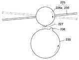
도 6 및 도 7은 본 발명의 제2 실시예에 따른 폐토너 수집장치를 도시한 사시도 및 단면도이며, 도 8은 본 발명의 제2 실시예에 따른 폐토너 수집장치의 교란판을 왕복 회전시키는 구성을 도시한 도면이다.6 and 7 are a perspective view and a cross-sectional view showing a waste toner collection device according to a second embodiment of the present invention, Figure 8 is a reciprocating rotation of the disturbing plate of the waste toner collection device according to a second embodiment of the present invention It is a figure which shows a structure.
도 6 내지 도 8을 참조하면, 본 발명의 제2 실시예에 따른 폐토너 수집장치도, 상술한 제1 실시예와 마찬가지로 감광드럼(114) 외주면에 접촉하여 폐토너를 긁어내 분리하는 클리닝 블레이드(222)와, 상기 폐토너가 모여 수용되는 폐토너 컨테이너(233)와, 상기 클리닝 블레이드(222)와 지지프레임(223)과 현상유닛 하우징(미도시)에 의해 한정되는 폐토너 통로와, 상기 폐토너 통로 내부에서 왕복운동하며 폐토너의 정체를 억제하는 교란판(225)를 구비한다.6 to 8, the waste toner collecting device according to the second embodiment of the present invention also contacts the outer peripheral surface of the
상기 교란판(225)은 감광드럼(114)의 길이방향으로 연장된 샤프트(226)와, 상기 샤프트(226)에 고정된 시트(sheet, 230)를 구비한다. 폐토너가 상기 시트(230)를 가로질러 통과할 수 있도록, 상기 시트(230)에는 통공(231)들이 형성되어 있다. 상기 샤프트(226)의 일단(226a)은 폐토너 컨테이너(233)의 일 측벽을 관통하여 회전 가능하게 폐토너 컨테이너(233)에 지지되어 자유단이 되고, 타단(226b)은 폐토너 컨테이너(233)의 타측 내면에 회전 불가능하게 고정 부착되어 고정단이 된다. 상기 샤프트(226)는 스프링의 소재로 사용되는 스프링강과 같은 금속으로 이루어져, 상기 자유단(226a)이 외력에 의해 소정 각도만큼 회전하더라도 그 외력이 제거되면 탄성에 의해 원위치로 복원된다.The
상기 샤프트(226)의 자유단(226a)에는 그 외주면에서 돌출된 돌기인 어셉터(acceptor, 227)가 마련된다. 폐토너 컨테이너(233) 외부에는 외주면에서 돌출된 돌기인 푸셔(pusher, 236)가 마련된 회전체(235)에 위치한다. 도시되진 않았으나 상기 회전체(235)는 현상롤러(115, 도 2 참조)에 회전력을 제공하는 현상롤러 구동기어와 치합되어 있다. 따라서, 화상형성과정이 개시되면 도 8에 도시된 바와 같이 회전체(235)가 회전하게 되며, 상기 회전체(235)가 회전하면 푸셔(236)가 어셉터(227)을 접촉 가압하여 샤프트(226)의 자유단(226a)도 시계방향으로 소정 각도만큼 회전하게 된다. 상기 회전체(235)가 더욱 회전하여 푸셔(236)가 어셉터(227)를 치고 지나가게 되면, 상기 자유단(226a)은 탄성 복원력에 의해 반시계방향으로 회전하여 원위치로 복귀한다. 이와 같이 샤프트(226)가 주기적으로 소정 각도만큼 왕복 회전운동하면서, 상기 샤프트(226)에 고정된 시트(230)도 왕복 회전운동한다. 이에 따라 클리닝 블레이드(222)에 의해 감광드럼(114)에서 분리된 폐토너가 상기 시트(230)에 의해 교란되며, 폐토너 통로에서 정체되지 않고 폐토너 컨테이너(233)를 향해 이동하게 된다.The
본 발명은 도면에 도시된 실시예를 참고로 설명되었으나 이는 예시적인 것에 불과하며, 당해 분야에서 통상의 지식을 가진 자라면 이로부터 다양한 변형 및 균등한 타 실시예가 가능함을 이해할 수 있을 것이다. 따라서 본 발명의 진정한 보호범위는 첨부된 특허청구범위에 의해서만 정해져야 할 것이다.Although the present invention has been described with reference to the embodiments shown in the drawings, this is merely exemplary, and it will be understood by those skilled in the art that various modifications and equivalent other embodiments are possible. Therefore, the true scope of protection of the present invention should be defined only by the appended claims.
본 발명에 따른 폐토너 수집장치, 및 이를 구비한 전자사진방식 화상형성장치는, 교란판이 폐토너의 정체를 억제하여, 감광매체의 원활한 회전을 촉진하고 감광매체 외주면의 오염을 방지한다. 이에 따라 인쇄화상의 품질 향상을 기대할 수 있다.The waste toner collecting device and the electrophotographic image forming apparatus having the same according to the present invention have a disturbing plate to suppress the waste toner, thereby promoting smooth rotation of the photosensitive medium and preventing contamination of the outer circumferential surface of the photosensitive medium. As a result, the quality of the printed image can be expected.
Claims (16)
Translated fromKoreanPriority Applications (4)
| Application Number | Priority Date | Filing Date | Title |
|---|---|---|---|
| KR1020040056424AKR100601694B1 (en) | 2004-07-20 | 2004-07-20 | Waste toner collecting device, and electrophotographic image forming apparatus having same |
| US11/128,287US7245867B2 (en) | 2004-07-20 | 2005-05-13 | Waste toner collecting apparatus and electrophotographic image forming device including the same |
| CN2005100820567ACN100407072C (en) | 2004-07-20 | 2005-07-05 | Waste toner collecting device and electrophotographic image forming apparatus including the same |
| JP2005204774AJP2006031006A (en) | 2004-07-20 | 2005-07-13 | Waste toner collecting device and electrophotographic image forming apparatus having the same |
Applications Claiming Priority (1)
| Application Number | Priority Date | Filing Date | Title |
|---|---|---|---|
| KR1020040056424AKR100601694B1 (en) | 2004-07-20 | 2004-07-20 | Waste toner collecting device, and electrophotographic image forming apparatus having same |
Publications (2)
| Publication Number | Publication Date |
|---|---|
| KR20060007588A KR20060007588A (en) | 2006-01-26 |
| KR100601694B1true KR100601694B1 (en) | 2006-07-14 |
Family
ID=35657298
Family Applications (1)
| Application Number | Title | Priority Date | Filing Date |
|---|---|---|---|
| KR1020040056424AExpired - Fee RelatedKR100601694B1 (en) | 2004-07-20 | 2004-07-20 | Waste toner collecting device, and electrophotographic image forming apparatus having same |
Country Status (4)
| Country | Link |
|---|---|
| US (1) | US7245867B2 (en) |
| JP (1) | JP2006031006A (en) |
| KR (1) | KR100601694B1 (en) |
| CN (1) | CN100407072C (en) |
Families Citing this family (13)
| Publication number | Priority date | Publication date | Assignee | Title |
|---|---|---|---|---|
| KR100667322B1 (en)* | 2005-01-19 | 2007-01-12 | 삼성전자주식회사 | Waste toner transfer device and toner cartridge having same |
| JP4819424B2 (en)* | 2005-07-11 | 2011-11-24 | 株式会社リコー | Image forming apparatus |
| JP4755956B2 (en) | 2006-08-28 | 2011-08-24 | 株式会社リコー | Inkjet recording device |
| JP4298733B2 (en)* | 2006-09-25 | 2009-07-22 | シャープ株式会社 | Developer recovery apparatus and image forming apparatus including the same |
| US7970336B2 (en) | 2007-02-05 | 2011-06-28 | Ricoh Company, Limited | Powder housing unit and image forming apparatus with powder housing unit |
| KR100906340B1 (en)* | 2007-03-27 | 2009-07-06 | 삼성전자주식회사 | Cleaning apparatus and image forming apparatus having same |
| KR100930044B1 (en)* | 2007-03-27 | 2009-12-08 | 삼성전자주식회사 | Developing unit of the image forming apparatus |
| KR100941421B1 (en)* | 2008-02-21 | 2010-02-10 | 삼성전자주식회사 | Developer storage device and image forming device having same |
| JP5353589B2 (en)* | 2009-09-15 | 2013-11-27 | 富士ゼロックス株式会社 | Cleaning device, image forming unit, and image forming apparatus |
| CN102540819B (en)* | 2012-01-06 | 2014-03-12 | 珠海天威飞马打印耗材有限公司 | Carbon powder box |
| JP6256297B2 (en)* | 2014-10-29 | 2018-01-10 | 京セラドキュメントソリューションズ株式会社 | Waste toner container and image forming apparatus |
| JP2020166150A (en)* | 2019-03-29 | 2020-10-08 | キヤノン株式会社 | Cleaning unit, cartridge, image forming device |
| JP2020166144A (en) | 2019-03-29 | 2020-10-08 | キヤノン株式会社 | Cleaning unit, cartridge, image forming device |
Family Cites Families (14)
| Publication number | Priority date | Publication date | Assignee | Title |
|---|---|---|---|---|
| JPS55124172A (en)* | 1979-03-16 | 1980-09-25 | Ricoh Co Ltd | Conveying device of powder toner |
| US4227618A (en)* | 1979-06-21 | 1980-10-14 | The Continental Group, Inc. | Expansion section for tamper-indicating ring of squeeze-off closure |
| FR2614409B1 (en) | 1987-04-23 | 1989-07-21 | Begon Jean | SWORD BLADE |
| JPH06735Y2 (en) | 1987-04-27 | 1994-01-05 | オ−バル機器工業株式会社 | Rotation transmission mechanism in volumetric flow meter |
| US5202728A (en)* | 1988-05-09 | 1993-04-13 | Mita Industrial Co., Ltd. | Image-forming machine with improved developer agitating means, developer regulating blade means, cleaning device, and toner recovery system |
| JP3122783B2 (en)* | 1995-03-03 | 2001-01-09 | シャープ株式会社 | Image forming device |
| JP3604840B2 (en)* | 1996-09-30 | 2004-12-22 | キヤノン株式会社 | Cleaning device and process cartridge |
| JPH10301460A (en)* | 1997-04-30 | 1998-11-13 | Fuji Xerox Co Ltd | Cleaner |
| JPH11223977A (en) | 1998-02-09 | 1999-08-17 | Ricoh Co Ltd | Image forming device |
| JP3692232B2 (en)* | 1998-02-24 | 2005-09-07 | 株式会社リコー | Cleaning device in image forming apparatus, and image forming apparatus provided with the cleaning device |
| JP2000155457A (en) | 1998-11-19 | 2000-06-06 | Murata Mach Ltd | Image recorder |
| KR20030017913A (en) | 2001-08-25 | 2003-03-04 | 한국후지제록스 주식회사 | Apparatus for refeeding the waste toner |
| JP2003248401A (en) | 2002-02-26 | 2003-09-05 | Canon Inc | Image forming device |
| JP2003307988A (en)* | 2002-04-15 | 2003-10-31 | Canon Inc | Image forming device |
- 2004
- 2004-07-20KRKR1020040056424Apatent/KR100601694B1/ennot_activeExpired - Fee Related
- 2005
- 2005-05-13USUS11/128,287patent/US7245867B2/ennot_activeExpired - Lifetime
- 2005-07-05CNCN2005100820567Apatent/CN100407072C/ennot_activeExpired - Fee Related
- 2005-07-13JPJP2005204774Apatent/JP2006031006A/enactivePending
Also Published As
| Publication number | Publication date |
|---|---|
| JP2006031006A (en) | 2006-02-02 |
| CN100407072C (en) | 2008-07-30 |
| CN1725125A (en) | 2006-01-25 |
| US7245867B2 (en) | 2007-07-17 |
| KR20060007588A (en) | 2006-01-26 |
| US20060018691A1 (en) | 2006-01-26 |
Similar Documents
| Publication | Publication Date | Title |
|---|---|---|
| US7903994B2 (en) | Image forming apparatus | |
| KR100601694B1 (en) | Waste toner collecting device, and electrophotographic image forming apparatus having same | |
| JPH11296042A (en) | Electrophotographic image forming apparatus | |
| US20100290818A1 (en) | Image-Forming Device Having a Belt Cleaning Unit | |
| JP3593792B2 (en) | Printing process unit | |
| JP2005114756A (en) | Image forming apparatus | |
| JP4575339B2 (en) | Image processing apparatus and image processing unit | |
| US7729654B2 (en) | Cleaning apparatus and image forming apparatus | |
| JPH1010939A (en) | Image forming device | |
| JP2003131479A (en) | Developing device, process cartridge and image forming device | |
| JP2003162191A (en) | Toner conveying device, process cartridge having the same, and electrophotographic image forming apparatus | |
| JP2003241597A (en) | Photosensitive drum cleaning device for wet printer | |
| JPH09171338A (en) | Color image forming equipment | |
| JP2000227700A (en) | Image forming device | |
| JP5288975B2 (en) | Image forming apparatus | |
| JP2004252389A (en) | Electrophotographic color printing apparatus | |
| JP2004271968A (en) | Image forming apparatus and cleaning apparatus | |
| JP3973791B2 (en) | Process cartridge for image forming apparatus, image forming apparatus | |
| JP3919351B2 (en) | Charging roller cleaning device, process cartridge, and electrophotographic image forming apparatus | |
| JP2025144669A (en) | Developer container, image forming unit, and image forming apparatus | |
| JP2002258717A (en) | Process cartridge and image forming apparatus | |
| KR20060005192A (en) | Waste toner collection device and electrophotographic image forming apparatus having the same | |
| JPH04219779A (en) | Color electrophotographic device cleaning device | |
| JPH0990837A (en) | Cleaning equipment | |
| JP2000221767A (en) | Electrophotographic image forming apparatus |
Legal Events
| Date | Code | Title | Description |
|---|---|---|---|
| A201 | Request for examination | ||
| PA0109 | Patent application | St.27 status event code:A-0-1-A10-A12-nap-PA0109 | |
| PA0201 | Request for examination | St.27 status event code:A-1-2-D10-D11-exm-PA0201 | |
| R17-X000 | Change to representative recorded | St.27 status event code:A-3-3-R10-R17-oth-X000 | |
| PN2301 | Change of applicant | St.27 status event code:A-3-3-R10-R13-asn-PN2301 St.27 status event code:A-3-3-R10-R11-asn-PN2301 | |
| PN2301 | Change of applicant | St.27 status event code:A-3-3-R10-R13-asn-PN2301 St.27 status event code:A-3-3-R10-R11-asn-PN2301 | |
| E902 | Notification of reason for refusal | ||
| PE0902 | Notice of grounds for rejection | St.27 status event code:A-1-2-D10-D21-exm-PE0902 | |
| PG1501 | Laying open of application | St.27 status event code:A-1-1-Q10-Q12-nap-PG1501 | |
| E13-X000 | Pre-grant limitation requested | St.27 status event code:A-2-3-E10-E13-lim-X000 | |
| P11-X000 | Amendment of application requested | St.27 status event code:A-2-2-P10-P11-nap-X000 | |
| P13-X000 | Application amended | St.27 status event code:A-2-2-P10-P13-nap-X000 | |
| E701 | Decision to grant or registration of patent right | ||
| PE0701 | Decision of registration | St.27 status event code:A-1-2-D10-D22-exm-PE0701 | |
| GRNT | Written decision to grant | ||
| PR0701 | Registration of establishment | St.27 status event code:A-2-4-F10-F11-exm-PR0701 | |
| PR1002 | Payment of registration fee | St.27 status event code:A-2-2-U10-U11-oth-PR1002 Fee payment year number:1 | |
| PG1601 | Publication of registration | St.27 status event code:A-4-4-Q10-Q13-nap-PG1601 | |
| PR1001 | Payment of annual fee | St.27 status event code:A-4-4-U10-U11-oth-PR1001 Fee payment year number:4 | |
| PR1001 | Payment of annual fee | St.27 status event code:A-4-4-U10-U11-oth-PR1001 Fee payment year number:5 | |
| PR1001 | Payment of annual fee | St.27 status event code:A-4-4-U10-U11-oth-PR1001 Fee payment year number:6 | |
| R18-X000 | Changes to party contact information recorded | St.27 status event code:A-5-5-R10-R18-oth-X000 | |
| PR1001 | Payment of annual fee | St.27 status event code:A-4-4-U10-U11-oth-PR1001 Fee payment year number:7 | |
| FPAY | Annual fee payment | Payment date:20130627 Year of fee payment:8 | |
| PR1001 | Payment of annual fee | St.27 status event code:A-4-4-U10-U11-oth-PR1001 Fee payment year number:8 | |
| FPAY | Annual fee payment | Payment date:20140627 Year of fee payment:9 | |
| PR1001 | Payment of annual fee | St.27 status event code:A-4-4-U10-U11-oth-PR1001 Fee payment year number:9 | |
| FPAY | Annual fee payment | Payment date:20150629 Year of fee payment:10 | |
| PR1001 | Payment of annual fee | St.27 status event code:A-4-4-U10-U11-oth-PR1001 Fee payment year number:10 | |
| FPAY | Annual fee payment | Payment date:20160629 Year of fee payment:11 | |
| PR1001 | Payment of annual fee | St.27 status event code:A-4-4-U10-U11-oth-PR1001 Fee payment year number:11 | |
| PN2301 | Change of applicant | St.27 status event code:A-5-5-R10-R11-asn-PN2301 | |
| PN2301 | Change of applicant | St.27 status event code:A-5-5-R10-R14-asn-PN2301 | |
| FPAY | Annual fee payment | Payment date:20170626 Year of fee payment:12 | |
| PR1001 | Payment of annual fee | St.27 status event code:A-4-4-U10-U11-oth-PR1001 Fee payment year number:12 | |
| PN2301 | Change of applicant | St.27 status event code:A-5-5-R10-R13-asn-PN2301 St.27 status event code:A-5-5-R10-R11-asn-PN2301 | |
| PR1001 | Payment of annual fee | St.27 status event code:A-4-4-U10-U11-oth-PR1001 Fee payment year number:13 | |
| PN2301 | Change of applicant | St.27 status event code:A-5-5-R10-R13-asn-PN2301 St.27 status event code:A-5-5-R10-R11-asn-PN2301 | |
| PN2301 | Change of applicant | St.27 status event code:A-5-5-R10-R11-asn-PN2301 | |
| PN2301 | Change of applicant | St.27 status event code:A-5-5-R10-R14-asn-PN2301 | |
| FPAY | Annual fee payment | Payment date:20190701 Year of fee payment:14 | |
| PR1001 | Payment of annual fee | St.27 status event code:A-4-4-U10-U11-oth-PR1001 Fee payment year number:14 | |
| PR1001 | Payment of annual fee | St.27 status event code:A-4-4-U10-U11-oth-PR1001 Fee payment year number:15 | |
| PC1903 | Unpaid annual fee | St.27 status event code:A-4-4-U10-U13-oth-PC1903 Not in force date:20210711 Payment event data comment text:Termination Category : DEFAULT_OF_REGISTRATION_FEE | |
| PC1903 | Unpaid annual fee | St.27 status event code:N-4-6-H10-H13-oth-PC1903 Ip right cessation event data comment text:Termination Category : DEFAULT_OF_REGISTRATION_FEE Not in force date:20210711 |