KR100600788B1 - Volatile organic solvent concentration automatic control device and image forming device - Google Patents
Volatile organic solvent concentration automatic control device and image forming deviceDownload PDFInfo
- Publication number
- KR100600788B1 KR100600788B1KR1020040075383AKR20040075383AKR100600788B1KR 100600788 B1KR100600788 B1KR 100600788B1KR 1020040075383 AKR1020040075383 AKR 1020040075383AKR 20040075383 AKR20040075383 AKR 20040075383AKR 100600788 B1KR100600788 B1KR 100600788B1
- Authority
- KR
- South Korea
- Prior art keywords
- volatile organic
- organic solvent
- vapor
- housing
- cooling
- Prior art date
- Legal status (The legal status is an assumption and is not a legal conclusion. Google has not performed a legal analysis and makes no representation as to the accuracy of the status listed.)
- Expired - Fee Related
Links
Images


Classifications
- B—PERFORMING OPERATIONS; TRANSPORTING
- B41—PRINTING; LINING MACHINES; TYPEWRITERS; STAMPS
- B41J—TYPEWRITERS; SELECTIVE PRINTING MECHANISMS, i.e. MECHANISMS PRINTING OTHERWISE THAN FROM A FORME; CORRECTION OF TYPOGRAPHICAL ERRORS
- B41J29/00—Details of, or accessories for, typewriters or selective printing mechanisms not otherwise provided for
- B41J29/377—Cooling or ventilating arrangements
- G—PHYSICS
- G03—PHOTOGRAPHY; CINEMATOGRAPHY; ANALOGOUS TECHNIQUES USING WAVES OTHER THAN OPTICAL WAVES; ELECTROGRAPHY; HOLOGRAPHY
- G03G—ELECTROGRAPHY; ELECTROPHOTOGRAPHY; MAGNETOGRAPHY
- G03G21/00—Arrangements not provided for by groups G03G13/00 - G03G19/00, e.g. cleaning, elimination of residual charge
- B—PERFORMING OPERATIONS; TRANSPORTING
- B01—PHYSICAL OR CHEMICAL PROCESSES OR APPARATUS IN GENERAL
- B01D—SEPARATION
- B01D5/00—Condensation of vapours; Recovering volatile solvents by condensation
- B01D5/0003—Condensation of vapours; Recovering volatile solvents by condensation by using heat-exchange surfaces for indirect contact between gases or vapours and the cooling medium
- B01D5/0015—Plates
- B—PERFORMING OPERATIONS; TRANSPORTING
- B01—PHYSICAL OR CHEMICAL PROCESSES OR APPARATUS IN GENERAL
- B01D—SEPARATION
- B01D53/00—Separation of gases or vapours; Recovering vapours of volatile solvents from gases; Chemical or biological purification of waste gases, e.g. engine exhaust gases, smoke, fumes, flue gases, aerosols
- B01D53/002—Separation of gases or vapours; Recovering vapours of volatile solvents from gases; Chemical or biological purification of waste gases, e.g. engine exhaust gases, smoke, fumes, flue gases, aerosols by condensation
- B—PERFORMING OPERATIONS; TRANSPORTING
- B01—PHYSICAL OR CHEMICAL PROCESSES OR APPARATUS IN GENERAL
- B01D—SEPARATION
- B01D53/00—Separation of gases or vapours; Recovering vapours of volatile solvents from gases; Chemical or biological purification of waste gases, e.g. engine exhaust gases, smoke, fumes, flue gases, aerosols
- B01D53/34—Chemical or biological purification of waste gases
- B01D53/74—General processes for purification of waste gases; Apparatus or devices specially adapted therefor
- B01D53/86—Catalytic processes
- B01D53/8678—Removing components of undefined structure
- B01D53/8687—Organic components
- B—PERFORMING OPERATIONS; TRANSPORTING
- B01—PHYSICAL OR CHEMICAL PROCESSES OR APPARATUS IN GENERAL
- B01D—SEPARATION
- B01D53/00—Separation of gases or vapours; Recovering vapours of volatile solvents from gases; Chemical or biological purification of waste gases, e.g. engine exhaust gases, smoke, fumes, flue gases, aerosols
- B01D53/34—Chemical or biological purification of waste gases
- B01D53/74—General processes for purification of waste gases; Apparatus or devices specially adapted therefor
- B01D53/86—Catalytic processes
- B01D53/869—Multiple step processes
- B—PERFORMING OPERATIONS; TRANSPORTING
- B41—PRINTING; LINING MACHINES; TYPEWRITERS; STAMPS
- B41J—TYPEWRITERS; SELECTIVE PRINTING MECHANISMS, i.e. MECHANISMS PRINTING OTHERWISE THAN FROM A FORME; CORRECTION OF TYPOGRAPHICAL ERRORS
- B41J2/00—Typewriters or selective printing mechanisms characterised by the printing or marking process for which they are designed
- B41J2/005—Typewriters or selective printing mechanisms characterised by the printing or marking process for which they are designed characterised by bringing liquid or particles selectively into contact with a printing material
- B41J2/01—Ink jet
- G—PHYSICS
- G03—PHOTOGRAPHY; CINEMATOGRAPHY; ANALOGOUS TECHNIQUES USING WAVES OTHER THAN OPTICAL WAVES; ELECTROGRAPHY; HOLOGRAPHY
- G03G—ELECTROGRAPHY; ELECTROPHOTOGRAPHY; MAGNETOGRAPHY
- G03G15/00—Apparatus for electrographic processes using a charge pattern
- G03G15/01—Apparatus for electrographic processes using a charge pattern for producing multicoloured copies
- G03G15/0142—Structure of complete machines
- G03G15/0147—Structure of complete machines using a single reusable electrographic recording member
- G03G15/0152—Structure of complete machines using a single reusable electrographic recording member onto which the monocolour toner images are superposed before common transfer from the recording member
- G03G15/0163—Structure of complete machines using a single reusable electrographic recording member onto which the monocolour toner images are superposed before common transfer from the recording member primary transfer to the final recording medium
- G—PHYSICS
- G03—PHOTOGRAPHY; CINEMATOGRAPHY; ANALOGOUS TECHNIQUES USING WAVES OTHER THAN OPTICAL WAVES; ELECTROGRAPHY; HOLOGRAPHY
- G03G—ELECTROGRAPHY; ELECTROPHOTOGRAPHY; MAGNETOGRAPHY
- G03G21/00—Arrangements not provided for by groups G03G13/00 - G03G19/00, e.g. cleaning, elimination of residual charge
- G03G21/20—Humidity or temperature control also ozone evacuation; Internal apparatus environment control
- G03G21/206—Conducting air through the machine, e.g. for cooling, filtering, removing gases like ozone
- B—PERFORMING OPERATIONS; TRANSPORTING
- B01—PHYSICAL OR CHEMICAL PROCESSES OR APPARATUS IN GENERAL
- B01D—SEPARATION
- B01D2255/00—Catalysts
- B01D2255/10—Noble metals or compounds thereof
- B01D2255/102—Platinum group metals
- B01D2255/1021—Platinum
- B—PERFORMING OPERATIONS; TRANSPORTING
- B01—PHYSICAL OR CHEMICAL PROCESSES OR APPARATUS IN GENERAL
- B01D—SEPARATION
- B01D2257/00—Components to be removed
- B01D2257/70—Organic compounds not provided for in groups B01D2257/00 - B01D2257/602
- B01D2257/708—Volatile organic compounds V.O.C.'s
Landscapes
- Chemical & Material Sciences (AREA)
- Engineering & Computer Science (AREA)
- Chemical Kinetics & Catalysis (AREA)
- Environmental & Geological Engineering (AREA)
- Analytical Chemistry (AREA)
- General Chemical & Material Sciences (AREA)
- Oil, Petroleum & Natural Gas (AREA)
- Physics & Mathematics (AREA)
- General Physics & Mathematics (AREA)
- Biomedical Technology (AREA)
- Health & Medical Sciences (AREA)
- Life Sciences & Earth Sciences (AREA)
- Atmospheric Sciences (AREA)
- Biodiversity & Conservation Biology (AREA)
- Ecology (AREA)
- Environmental Sciences (AREA)
- Control Or Security For Electrophotography (AREA)
- Wet Developing In Electrophotography (AREA)
- Exhaust Gas Treatment By Means Of Catalyst (AREA)
- Treating Waste Gases (AREA)
Abstract
Translated fromKoreanDescription
Translated fromKorean도 1은 종래기술에 의한 휘발성유기용제 처리장치를 구비하는 화상형성장치를 나타낸 개념도,1 is a conceptual diagram showing an image forming apparatus having a volatile organic solvent processing apparatus according to the prior art,
도 2는 본 발명에 의한 휘발성유기용제 농도 자동조절장치의 제1실시예를 나타낸 평면도,Figure 2 is a plan view showing a first embodiment of the apparatus for automatically adjusting the volatile organic solvent concentration according to the present invention,
도 3은 도 2의 휘발성유기용제 농도 자동조절장치의 정면도;Figure 3 is a front view of the volatile organic solvent concentration automatic control device of Figure 2;
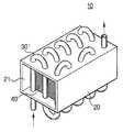
도 4는 도 2의 휘발성유기용제 농도 자동조절장치의 냉각튜브의 다른 예를 나타낸 사시도,4 is a perspective view showing another example of a cooling tube of the volatile organic solvent concentration automatic control device of FIG.
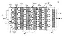
도 5는 본 발명에 의한 휘발성유기용제 농도 자동조절장치의 제2실시예를 나타낸 평면도,5 is a plan view showing a second embodiment of the apparatus for automatically adjusting the volatile organic solvent concentration according to the present invention;
도 6은 도 5의 휘발성유기용제 농도 자동조절장치의 정면도,6 is a front view of the volatile organic solvent concentration automatic control device of FIG.
도 7은 본 발명에 의한 휘발성유기용제 농도 자동조절장치를 구비한 화상형성장치를 나타낸 개념도이다.7 is a conceptual diagram illustrating an image forming apparatus including an automatic adjustment device for volatile organic solvent concentration according to the present invention.
*도면의 주요부분에 대한 부호의 설명** Description of the symbols for the main parts of the drawings *
10,50,103; 휘발성유기용제 농도 자동조절장치10,50,103; Volatile organic solvent concentration automatic control device
20,60; 하우징21,61,102; 인입구20,60;
23,63,104; 배출구30,30',70; 냉각튜브23,63,104;
30a,30b,30c,30d,30e,70a,70b,70c,70d,70e,70f,70g; 냉각튜브 열30a, 30b, 30c, 30d, 30e, 70a, 70b, 70c, 70d, 70e, 70f, 70g; Cooling tube heat
40,80; 다공성부재65; 증기안내판40,80;
100; 화상형성장치101; 화상형성유닛100; An
105; 촉매장치107; 배기구105;
본 발명은 습식 현상제(liquid toner)를 사용하여 인쇄하는 화상형성장치에서 발생하는 휘발성유기용제 증기를 처리하여 무해한 기체로 배출하는 촉매장치에 관한 것으로서, 보다 상세하게는 촉매장치로 인입되는 휘발성유기용제 증기의 농도를 일정 값 이하로 조절할 수 있는 휘발성유기용제 농도 자동조절장치 및 이를 구비한 화상형성장치에 관한 것이다.BACKGROUND OF THE
일반적으로 습식 현상제를 사용하여 인쇄를 하는 화상형성장치는 습식 현상제로 현상된 감광체의 화상을 종이와 같은 인쇄매체로 전사한 후, 화상이 전사된 인쇄매체를 고온/고압의 정착장치를 통과시킴으로써 전사된 화상을 인쇄매체에 정착시킨다. 화상을 정착시키는 과정에서 고온에 의해 습식 현상제를 구성하는 유기용제가 증발함으로써 휘발성유기용제(Volatile Organic Compound, VOC)의 증기가 발생하게 된다. 이러한 휘발성유기용제는 유해하기 때문에 그대로 대기중으로 방출 할 수 없다. 따라서, 습식 화상형성장치는 도 1에 도시된 바와 같이 화상형성유닛(3)에서 발생한 휘발성유기용제 증기를 무해한 기체로 만들어 배출하는 장치(5)를 갖고 있다. 화상형성장치(1)에서 휘발성유기용제 증기를 처리하기 위해 사용되는 장치(5)로는 주로 촉매장치가 사용된다. 촉매장치는 백금과 같은 촉매를 이용하여 휘발성유기용제 증기를 CO2, H2O 등의 무해한 기체로 분해하여 대기로 배출한다.In general, an image forming apparatus that prints using a wet developer transfers an image of a photosensitive member developed with a wet developer onto a print medium such as paper, and then passes the print medium on which the image is transferred through a high temperature / high pressure fixing device. The transferred image is fixed to a print medium. As the organic solvent constituting the wet developer evaporates at a high temperature in the process of fixing the image, vapor of a volatile organic compound (VOC) is generated. Since these volatile organic solvents are harmful, they cannot be released into the atmosphere as they are. Accordingly, the wet image forming apparatus has an
그런데 이와 같은 촉매장치는 화상형성장치에서 발생할 수 있는 휘발성유기용제 증기의 최대량을 기준으로 설계하게 된다. 그러나 인쇄 중에 항상 최대량의 휘발성유기용제 증기가 발생하는 것은 아니므로 촉매의 사용효율이 낮다는 문제점이 있다. 즉, 평균적으로 발생하는 휘발성유기용제 증기를 처리할 수 있는 촉매의 양에 비해 많은 양의 촉매를 사용하므로 화상형성장치의 비용을 높이는 요인이 된다.However, such a catalytic device is designed based on the maximum amount of volatile organic solvent vapor that can occur in the image forming apparatus. However, there is a problem that the use efficiency of the catalyst is low because the maximum amount of volatile organic solvent vapor is not always generated during printing. That is, since the catalyst is used in a large amount compared to the amount of the catalyst that can process the volatile organic solvent vapor generated on average, it is a factor to increase the cost of the image forming apparatus.
그러나, 비용을 줄이기 위해 휘발성유기용제 증기의 평균 발생량을 기초로 촉매장치를 설계하면, 평균 이상의 휘발성유기용제 증기가 발생하는 경우에는 촉매장치가 인입된 휘발성유기용제 증기를 완전히 처리하지 못하고 대기중으로 방출시키는 경우가 발생할 수 있다. 또, 휘발성유기용제를 분해하는 촉매반응이 발열반응이므로 설계용량을 넘는 휘발성유기용제 증기를 분해하는 경우에는 과열로 인해 촉매가 변성되어 그 성능을 잃어버리는 경우가 발생하여 촉매의 수명이 단축된다는 문제점이 있다.However, if the catalyst device is designed based on the average amount of volatile organic solvent vapor generated in order to reduce the cost, if the volatile organic solvent vapor above the average is generated, the catalyst device does not completely process the introduced volatile organic solvent vapor and releases it into the atmosphere. May occur. In addition, since the catalytic reaction for decomposing volatile organic solvents is an exothermic reaction, when decomposing volatile organic solvent vapors exceeding a design capacity, the catalyst may be denatured due to overheating and its performance may be lost. There is this.
본 발명은 상기와 같은 문제점을 감안하여 안출된 것으로서, 촉매장치에 화상형성장치에서 발생하는 휘발성유기용제 증기의 최대량을 처리할 수 있는 촉매량보다 적은 양의 촉매를 사용할 수 있도록 촉매장치로 인입되는 휘발성유기용제 증기의 농도를 일정값 이하로 유지시킬 수 있는 휘발성유기용제 농도 자동조절장치를 제공하는데 그 목적이 있다.The present invention has been made in view of the above problems, and the volatile flows into the catalyst device so that the catalyst can be used in the catalyst device so that the amount of catalyst less than the amount of catalyst capable of processing the maximum amount of the volatile organic solvent vapor generated in the image forming apparatus can be used. It is an object of the present invention to provide a device for automatically adjusting the concentration of volatile organic solvents capable of maintaining the concentration of the organic solvent vapor below a predetermined value.
본 발명의 다른 목적은 촉매장치에 일정 농도 이하의 휘발성유기용제 증기만 인입되도록 함으로써, 촉매의 수명을 연장시킬 수 있는 휘발성유기용제 농도 자동조절장치를 제공하는 것이다.Another object of the present invention is to provide a volatile organic solvent concentration automatic control device that can extend the life of the catalyst by allowing only the volatile organic solvent vapor of a certain concentration or less to be introduced into the catalyst device.
또한, 본 발명은 상기와 같은 휘발성유기용제 농도 자동조절장치를 구비함으로써 촉매장치의 설치 및 유지에 드는 비용을 절감할 수 있는 화상형성장치를 제공하는데 그 목적이 있다.In addition, an object of the present invention is to provide an image forming apparatus capable of reducing the cost of installing and maintaining the catalyst device by providing the automatic control of the volatile organic solvent concentration as described above.
상기와 같은 본 발명의 목적은, 휘발성유기용제의 증기가 인입되고 배출되는 인입구 및 배출구를 구비한 하우징; 상기 인입구로 인입된 휘발성유기용제의 증기를 냉각시키기 위한 냉각튜브; 및 응축된 휘발성유기용제가 맺히는 다공성부재;를 포함하는 휘발성유기용제 농도 자동조절장치를 제공함으로써 달성된다.An object of the present invention as described above, the housing having an inlet and an outlet through which the vapor of the volatile organic solvent is introduced and discharged; Cooling tube for cooling the vapor of the volatile organic solvent introduced into the inlet; And a porous member in which condensed volatile organic solvents are formed.
여기서, 상기 냉각튜브는 증기의 흐름방향에 대해 수직으로 상기 하우징을 관통하도록 설치된다. 이때, 상기 냉각튜브는 복수의 냉각튜브가 복수의 열(列)을 이루도록 배치되는 것이 바람직하다. 또한, 상기 복수의 냉각튜브 열의 각 열을 구 성하는 각각의 냉각튜브는 인접한 다른 열의 냉각튜브와 서로 엇갈리도록 배치된다.Here, the cooling tube is installed to pass through the housing perpendicular to the flow direction of the steam. At this time, the cooling tube is preferably arranged so that a plurality of cooling tubes form a plurality of rows (列). In addition, each cooling tube constituting each row of the plurality of cooling tube rows are arranged to be staggered with the cooling tubes of other adjacent rows.
또한, 상기 다공성부재는 상기 복수의 냉각튜브 열 사이사이에 설치된다. 이때, 상기 배출구의 직전에 상기 배출구에 밀착하여 다공성부재를 더 설치하는 것이 바람직하다. 상기 다공성부재는 촘촘한 철망, 솜, 스폰지 중의 어느 하나를 사용할 수 있다.In addition, the porous member is installed between the plurality of rows of cooling tubes. At this time, it is preferable to install the porous member in close contact with the outlet just before the outlet. The porous member may be any one of a dense wire mesh, cotton, sponge.
본 발명의 다른 측면에서, 상기와 같은 본 발명의 목적은, 휘발성유기용제의 증기가 인입되어 배출되는 인입구 및 배출구를 구비하며, 그 단면적이 상기 인입구의 단면적보다 넓은 하우징; 상기 인입구로 인입된 휘발성유기용제의 증기를 냉각시키기 위한 냉각튜브; 및 상기 인입구와 배출구 사이에 설치되며, 응축된 휘발성유기용제가 맺히는 다공성부재;를 포함하는 휘발성유기용제 농도 자동조절장치를 제공함으로써 달성된다.In another aspect of the present invention, an object of the present invention as described above comprises a inlet and an outlet through which the vapor of the volatile organic solvent is introduced into and discharged, the housing having a cross-sectional area larger than that of the inlet; Cooling tube for cooling the vapor of the volatile organic solvent introduced into the inlet; And a porous member disposed between the inlet and the outlet and condensed with the volatile organic solvent.
여기서, 상기 하우징의 단면은 직사각형으로 형성하고, 상기 냉각튜브는 상기 증기의 흐름방향에 대해 수직으로 상기 하우징을 관통하도록 설치된다.Here, the cross section of the housing is formed in a rectangular shape, the cooling tube is installed to pass through the housing perpendicular to the flow direction of the steam.
또한, 상기 냉각튜브는 복수의 냉각튜브가 복수의 열(列)을 이루도록 배치된 다.In addition, the cooling tube is arranged such that a plurality of cooling tubes form a plurality of rows.
또한, 상기 다공성부재는 상기 복수의 냉각튜브 열 사이사이에 설치되며, 상기 배출구의 직전에 상기 배출구에 밀착하여 다공성부재를 더 설치된다.In addition, the porous member is installed between the rows of the plurality of cooling tubes, the porous member is further installed in close contact with the outlet immediately before the outlet.
또한, 상기 하우징의 인입구 쪽에는 증기안내판이 설치된다.In addition, a vapor guide plate is installed at the inlet side of the housing.
본 발명의 또 다른 측면에서, 상기와 같은 본 발명의 목적은, 습식 현상제를 사용하여 인쇄를 수행하는 화상형성유닛; 상기 화상형성유닛으로부터 인입되는 휘발성유기용제 증기의 농도를 일정 값 이하로 조절하여 배출하는 휘발성유기용제 농도 자동조절장치; 및 상기 휘발성유기용제 농도 자동조절장치로부터 인입되는 휘발성유기용제의 증기를 처리하여 대기로 배출하는 촉매장치;를 포함하는 화상형성장치를 제공함으로써 달성된다.In another aspect of the present invention, an object of the present invention as described above, the image forming unit for performing printing using a wet developer; An automatic volatile organic solvent concentration adjusting device for discharging the volatile organic solvent vapor introduced from the image forming unit to a predetermined value or less; And a catalytic device for treating the vapor of the volatile organic solvent introduced from the volatile organic solvent concentration automatic control device and discharging the vapor to the atmosphere.
여기서, 상기 휘발성유기용제 농도 자동조절장치는, 상기 화상형성유닛과 연통되는 인입구와 상기 촉매장치와 연통되는 배출구를 구비하며, 상기 휘발성유기용제의 증기의 통로가 되는 하우징; 상기 인입구로 인입된 휘발성유기용제의 증기를 냉각시키기 위한 냉각튜브; 및 응축된 휘발성유기용제가 맺히는 다공성부재;를 포함한다.The volatile organic solvent concentration automatic control device may include a housing having an inlet port communicating with the image forming unit and an outlet port communicating with the catalyst device, the housing being a passage for the vapor of the volatile organic solvent; Cooling tube for cooling the vapor of the volatile organic solvent introduced into the inlet; And a porous member on which the condensed volatile organic solvent is formed.
이하, 첨부된 도면을 참조하여 본 발명에 의한 휘발성유기용제 농도 자동조절장치의 실시예들에 대하여 설명한다.Hereinafter, with reference to the accompanying drawings will be described embodiments of the apparatus for automatically adjusting the volatile organic solvent concentration according to the present invention.
도 2 및 도 3은 본 발명에 의한 휘발성유기용제 농도 자동조절장치의 제1실시예를 나타낸 평면도와 정면도이다.2 and 3 are a plan view and a front view showing a first embodiment of the apparatus for automatically adjusting the volatile organic solvent concentration according to the present invention.
도 2 및 도 3을 참조하면, 휘발성유기용제 농도 자동조절장치(10)는 하우징(20), 냉각튜브(30) 및 다공성부재(40)를 포함한다.2 and 3, the volatile organic solvent concentration
하우징(20)의 일단에는 화상형성장치의 화상형성유닛과 같이 휘발성유기용제 증기가 발생되는 곳과 연통되며 휘발성유기용제 증기가 인입되는 인입구(21)가 마련되고, 타단에는 휘발성유기용제 증기를 배출하며 촉매장치와 같이 휘발성유기용제 증기를 처리하는 장치와 연통되는 배출구(23)가 마련된다. 하우징(20)의 단면 형상은 원형으로 할 수 있으나 직사각형으로 하는 것이 바람직하다.One end of the
냉각튜브(30)는 하우징(20)의 내부에 인입구(21)와 배출구(23) 사이에 설치되며, 인입구(21)로 인입된 휘발성유기용제 증기를 일정 온도 이하로 냉각시킴으로써 배출구(23)로 배출되는 휘발성유기용제 증기의 농도가 일정 값 이하로 유지되도록 하는 작용을 한다. 냉각튜브(30)의 크기, 배열 및 배치등은 배출구(23)로 배출되는 휘발성유기용제 증기의 농도가 하우징(20)의 배출구(23)와 연결된 촉매장치의 설계농도 이하가 되도록 휘발성유기용제 증기의 온도를 낮출 수 있으면 다양하게 설계할 수 있다. 도 2 및 도 3에는 이와 같은 냉각튜브(30)의 일예가 도시되어 있다. 본 예에서는 냉각튜브(30)로 단면이 원형인 튜브를 사용하며, 복수의 냉각튜브(30)가 휘발성유기용제 증기의 흐름방향(화살표 A 방향)에 대해 수직으로 설치되어 있다. 즉, 복수의 냉각튜브(30)가 하우징(20)의 상하면(20a,20b)을 관통하여 설치되어 있다. 따라서 냉각튜브(30)의 외측으로 흐르는 휘발성유기용제 증기는 냉각튜브(30)의 내부를 관통하여 흐르는 공기에 의해 냉각되게 된다. 또, 냉각튜브(30)들은 복수의 열(30a,30b,30c,30d,30e)로 설치되며, 각각의 열은 복수의 냉각튜브(30a1,30a2,30a3)가 일렬을 이루고 있다. 이때, 배출되는 휘발성유기용제 증기의 온도는 냉각튜브(30)의 직경, 각 열(30a,30b,30c,30d,30e)을 이루는 냉각튜브(30a1,30a2,30a3)의 갯수 및 냉각튜브 열의 수를 조절함으로써 정할 수 있다. 도 2의 예에서는 3개의 냉각튜브(30a1,30a2,30a3)가 한 열(30a)을 이루고 이러한 열 5개(30a,30b,30c,30d,30e)가 평행하게 배치되어 있다. 또한, 복수의 냉각튜브(30)를 도 4에 도시한 냉각튜브(30')와 같이 하나로 연결하여 물과 같은 냉매가 흐르도록 함으로써 냉각튜브(30')의 냉각능력을 높일 수도 있다.The
다공성부재(40)는 하우징(20)의 인입구(21)로 인입된 휘발성유기용제 증기가 통과하여 흐를 수 있고, 휘발성유기용제 증기가 냉각튜브(30)에 의해 냉각되어 액체로 응축되는 경우 부착될 수 있도록 많은 구멍을 갖는 물질을 말한다. 즉 다공성부재(40)는 통과하는 증기의 농도가 높은 경우에 증기가 냉각되어 액체로 응축되면 그 액체를 표면에 맺힌 상태 그대로 유지함으로써, 후에 농도가 낮은 증기가 통과하는 경우에 맺힌 액체가 쉽게 증발될 수 있도록 하는 역할을 한다. 이러한 다공성부재(40)로는 일정한 두께를 갖도록 촘촘하게 형성된 철망, 스폰지, 솜 등이 사용될 수 있다. 본 실시예에서는 촘촘한 철망으로 형성된 다공성부재(40)가 도 2 및 도 3과 같이 냉각튜브의 열(30a,30b,30c,30d,30e) 사이사이에 설치되어 있다. 또한, 다공성부재(40)는 응축된 휘발성유기용제 입자가 직접 촉매장치로 인입되지 않도록 배출구(23)의 직전에 더 설치하는 것이 바람직하다(도 5 참조). 만일 다공성부재(40)를 사용하지 않는 경우에는 농도가 높은 휘발성유기용제 증기가 인입되는 경우에 응축되어 액체로 된 휘발성유기용제 입자는 하우징(20) 바닥에 모이게 된다. 그러나, 바닥에 모인 액체는 증발이 잘 일어나지 않기 때문에 낮은 농도의 휘발성유기용제 증기가 하우징(20)을 통과하는 경우에도 액체로 된 휘발성유기용제가 다시 증기로 되는 비율이 매우 적게 된다. 따라서, 유해한 휘발성유기용제의 대부분이 촉매장치에 의해 처리되지 못하고 하우징(20)에 액체 상태로 잔류하게 된다. 그러나 냉각튜브(30)의 외면 또는/및 하우징(20)의 내면에 냉각핀 등을 마련하여 농도가 높은 휘발성유기용제 증기가 통과하는 경우에는 냉각튜브(30) 외면이나 하 우징(20) 내면의 냉각핀 등에 증기가 응축되고, 농도가 낮은 휘발성유기용제 증기가 통과하는 경우에는 냉각핀 등에 맺힌 휘발성유기용제의 증발이 용이하게 일어날 수 있는 구조로 형성한 경우에는 반드시 다공성부재(40)를 사용해야 하는 것은 아니다. 즉 하우징(20) 내부의 구조를 다공성부재(40)가 행하는 기능을 할 수 있도록 형성하는 경우에는 별도의 다공성부재(40)를 사용하지 않을 수 있다.The
상기와 같은 구성을 갖는 휘발성유기용제 농도 자동조절장치의 작용에 대해 설명하면 다음과 같다.Referring to the operation of the volatile organic solvent concentration automatic control device having the configuration as described above are as follows.
하우징(20)의 인입구(21)로 인입된 휘발성유기용제 증기는 냉각튜브(30)와 다공성부재(40)를 통과하여 배출구(23)로 배출된다. 이때, 인입되는 휘발성유기용제 증기의 농도가 설계농도, 즉 배출구(23)에 연통된 촉매장치의 설계농도보다 높은 경우에는 통과하는 휘발성유기용제 증기의 일부가 냉각튜브(30)에 의해 냉각되어 액체로 응축되기 때문에 배출구(23)로 배출되는 휘발성유기용제 증기의 농도는 설계농도 이상이 되지 않는다. 응축된 휘발성유기용제는 하우징(20)의 바닥으로 떨어지지 않고 다공성부재(40)의 구멍 주위에 맺히게 된다. 또, 하우징(20)의 인입구(21)로 설계농도보다 낮은 농도의 휘발성유기용제 증기가 인입되는 경우에는, 통과하는 증기는 응축되지 않고 농도의 차이에 의해 다공성부재(40)에 응축되어 있던 휘발성유기용제가 증발하여 통과하는 휘발성유기용제 증기의 농도를 상승시키기 때문에 배출구(23)로 배출되는 휘발성유기용제 증기의 농도가 설계농도까지 상승될 수 있다. 만일 하우징(20) 내부에 응축된 휘발성유기용제가 없거나 그 양이 적은 경우에는 인입된 휘발성유기용제 증기는 인입된 농도 거의 그대로 배출된다. 즉, 휘발성유기용제 농도 자동조절장치(10)는 인입되는 휘발성유기용제 증기의 농도에 따라 응축기나 증발기로서 작용함으로써 배출구(23)로 배출되는 휘발성유기용제 증기의 농도가 일정 농도(촉매장치의 설계농도) 이하로 유지되도록 한다.The volatile organic solvent vapor introduced into the
도 5 및 도 6은 본 발명에 의한 휘발성유기용제 농도 자동조절장치의 제2실시예를 나타낸 평면도 및 정면도이다.5 and 6 are a plan view and a front view showing a second embodiment of the apparatus for automatically adjusting the volatile organic solvent concentration according to the present invention.
도 5 및 도 6을 참조하면, 제2실시예에 의한 휘발성유기용제 농도 자동조절장치(50)는 하우징(60), 냉각튜브(70) 및 다공성부재(80)를 포함한다.5 and 6, the volatile organic solvent concentration
하우징(60)의 일단에는 화상형성장치의 화상형성유닛과 같이 휘발성유기용제 증기가 발생되는 곳과 연통되며 휘발성유기용제 증기가 인입되는 인입구(61)가 마련되고, 타단에는 휘발성유기용제 증기를 배출하며 촉매장치와 같이 휘발성유기용제 증기를 처리하는 장치와 연통되는 배출구(63)가 마련된다. 이때, 인입구(61)의 단면적은 하우징(60)의 단면적보다 좁도록 형성된다. 따라서 인입구(61)로 들어오는 휘발성유기용제 증기의 유속이 떨어지게 된다. 인입되는 증기의 유속이 떨어지면, 냉각튜브(70)로 휘발성유기용제 증기를 냉각시키는 냉각효율이 상승한다. 또, 인입구(61)의 안쪽에는 인입되는 휘발성유기용제 증기의 흐름을 원할하게 안내하기 위해 증기안내판(65)을 설치하는 것이 바람직하다. 또한, 하우징(60)의 단면형상은 원형으로 할 수 있으나 도 5 및 도 6과 같이 직사각형으로 하는 것이 바람직하다.One end of the
냉각튜브(70)는 하우징(60)의 내부에 인입구(61)와 배출구(63) 사이에 설치되며, 인입구(61)로 인입된 휘발성유기용제 증기를 일정 온도 이하로 냉각시킴으로써 배출구(63)로 배출되는 휘발성유기용제 증기의 농도를 일정하게 유지하는 작용 을 한다. 냉각튜브(70)의 크기, 배열 및 배치 등은 배출구(63)로 배출되는 휘발성유기용제 증기의 농도가 하우징(60)의 배출구(63)와 연결된 촉매장치의 설계농도 이하가 되도록 휘발성유기용제 증기의 온도를 낮출 수 있으면 다양하게 설계할 수 있다. 즉, 냉각튜브(70)는 상기에서 설명한 제1실시예의 도 2와 같이 배치할 수도 있으나 본 실시예에서는 도 5와 같이 배치하였다. 본 실시예에서는 냉각튜브(70)로 단면이 원형인 튜브를 사용하며, 복수의 냉각튜브(70)가 휘발성유기용제 증기의 흐름방향(화살표 A 방향)에 대해 수직으로 설치되어 있다. 즉, 복수의 냉각튜브(70)가 하우징(60)의 상하면(60a,60b)을 관통하여 설치되어 있다. 따라서 냉각튜브(70)의 외측으로 흐르는 휘발성유기용제 증기는 냉각튜브(70)의 내부를 관통하여 흐르는 공기에 의해 냉각되게 된다. 또, 냉각튜브(70)들은 복수의 열(70a,70b,70c,70d,70e,70f,70g)로 설치되며, 각각의 열(70a,70b,70c,70d,70e,70f,70g)은 복수의 냉각튜브가 일렬(一列)을 이루고 있다. 그리고 인접하는 열을 구성하는 각각의 냉각튜브들은 서로 엇갈리도록 배치되어 있다. 즉, 도 5에 도시된 바와 같이 임의의 냉각튜브 열(70b)의 다음 냉각튜브 열(70c)을 구성하는 각각의 냉각튜브(70c1,70c2,70c3,70c4)는 그 전의 냉각튜브 열(70b)을 구성하는 각각의 냉각튜브(70b1,70b2,70b3,70b4,70b5) 사이의 공간을 마주보도록 배치되어 있다. 이때, 배출되는 휘발성유기용제 증기의 온도는 냉각튜브(70)의 직경, 냉각튜브 열의 수 및 각 열을 이루는 냉각튜브의 갯수를 조절함으로써 결정할 수 있다. 도 5의 예에서는 3개 내지 5개의 냉각튜브가 한 열을 이루고 이러한 열 7개(70a,70b,70c,70d,70e,70f,70g)가 평행하게 배치되어 있다. 또한, 복 수의 냉각튜브를 하나로 연결하고 물과 같은 냉매가 흐르도록 함으로써 냉각튜브(70)의 냉각능력을 높일 수도 있다(도 4 참조).The cooling
다공성부재(80)는 상술한 제1실시예에 의한 휘발성유기용제 농도 자동조절장치(10)의 다공성부재(40)와 동일하므로 상세한 설명은 생략한다.Since the
상기와 같이 구성된 제2실시예에 의한 휘발성유기용제 농도 자동조절장치(50)의 작용에 대해 설명하면 다음과 같다.Referring to the operation of the volatile organic solvent concentration
하우징(60)의 인입구(61)로 인입된 휘발성유기용제 증기는 인입구(61)의 단면적보다 넓은 하우징(60)을 통과하게 되므로 유속이 떨어지게 된다. 이때, 인입된 휘발성유기용제 증기는 증기안내판(65)을 따라 흐르게 되므로 하우징(60) 내부에 대해 균일하게 퍼지게 된다. 하우징(60)에 인입되어 유속이 저하된 휘발성유기용제 증기는 냉각튜브(70)의 주위와 다공성부재(80)를 천천히 통과하여 배출구(63)로 배출된다. 이때, 휘발성유기용제 농도 자동조절장치(50)가 하우징(60)으로 인입되는 휘발성유기용제 증기의 농도에 따라 응축기나 증발기로 작용함으로써 배출구(63)로 배출되는 휘발성유기용제 증기의 농도를 일정 농도 이하로 유지되도록 하는 작용은 상술한 제1실시예에 의한 휘발성유기용제 농도 자동조절장치(10)와 동일하므로 상세한 설명은 생략한다.Since the volatile organic solvent vapor introduced into the
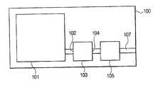
도 7은 본 발명에 의한 휘발성유기용제 농도 자동조절장치를 구비한 화상형성장치의 일예를 나타낸 개념도이다.7 is a conceptual diagram illustrating an example of an image forming apparatus including an automatic adjustment device for volatile organic solvent concentration according to the present invention.
도 7을 참조하면, 화상형성장치(100)는 습식 현상제를 사용하여 인쇄를 수행하는 화상형성유닛(101)과, 화상형성유닛(101)으로부터 인입되는 휘발성유기용제 증기의 농도를 일정하게 조절하여 배출하는 휘발성유기용제 농도 자동조절장치(103) 및 휘발성유기용제 농도 자동조절장치(103)로부터 인입되는 휘발성유기용제의 증기를 처리하여 외부로 배출하는 촉매장치(105)를 포함한다.Referring to FIG. 7, the
화상형성유닛(101)은 감광체에 형성된 정전잠상을 습식 현상제로 현상하여 화상을 형성하고, 감광체의 화상을 종이와 같은 인쇄매체로 전사한다. 다음으로 화상이 전사된 인쇄매체가 고온/고압의 정착장치를 통과하도록 함으로써 전사된 화상을 인쇄매체에 정착시킨다. 이때 화상을 형성하는 습식 현상제를 정착시키는 과정에서 고온에 의해 습식 현상제를 구성하는 성분이 증발하여 휘발성유기용제 증기가 발생한다.The
휘발성유기용제 농도 자동조절장치(103)는 그 인입구(102)는 화상형성유닛(101)과 연통되도록 설치되고 배출구(104)는 촉매장치(105)와 연통되도록 설치되어 있으며, 화상형성유닛(101)으로부터 인입되는 휘발성유기용제 증기의 농도를 촉매장치(105)의 설계농도 이하로 조절하여 촉매장치(105)로 배출한다. 그 구성은 상술한 실시예와 동일하므로 상세한 설명은 생략한다.The volatile organic solvent concentration
촉매장치(105)는 인입된 휘발성유기용제 증기를 무해한 성분으로 분해할 수 있도록 구성된다. 일반적인 습식 현상제를 사용하는 화상형성장치(100)에서는 통상 휘발성유기용제 증기를 분해하기 위해 백금촉매를 사용한다. 또한, 휘발성유기용제 증기는 고온(대략 200℃ 이상)에서 반응하므로 촉매장치(105)는 인입된 증기의 온도를 반응온도까지 상승시키는 히터를 구비한다. 또, 촉매장치(105)는 분해된 기체가 화상형성장치(100)의 외부로 배출되도록 하는 배기구(107)와 연통되어 있다.The
인쇄명령에 의해 화상형성유닛(101)에서 인쇄매체에 인쇄가 수행되면, 휘발성유기용제 증기가 발생한다. 발생되는 휘발성유기용제 증기의 양은 인쇄내용에 따라 변화한다. 발생된 휘발성유기용제 증기는 화상형성유닛(101)과 연통된 인입구(102)를 통해 휘발성유기용제 농도 자동조절장치(103)로 인입된다. 휘발성유기용제 농도 자동조절장치(103)로 인입된 증기는 상기에서 설명한 바와 같이 그 농도에 따라 응축이나 증발이 발생하여 일정한 농도 이하로 되어 배출구(104)를 통해 촉매장치(105)로 인입된다. 촉매장치(105)로 인입된 휘발성유기용제 증기는 촉매에 의해 CO2, H2O 등과 같이 무해한 기체로 분해되어 배기구(107)을 통해 화상형성장치(100) 외부로 배출된다.When printing is performed on the print medium in the
이상에서 설명한 바와 같이 본 발명에 의한 휘발성유기용제 농도 자동조절장치는 촉매장치로 인입되는 휘발성유기용제 증기의 농도를 최대 발생량 이하의 일정 값 이하로 유지할 수 있기 때문에, 본 장치를 촉매장치의 전단에 설치하면 화상형성기에서 발생하는 최대 휘발성유기용제 증기량을 처리할 수 있는 량의 촉매를 사용하였던 종래의 촉매장치보다 촉매 사용량을 줄일 수 있다.As described above, the apparatus for automatically adjusting the volatile organic solvent concentration according to the present invention can maintain the concentration of the volatile organic solvent vapor introduced into the catalyst device at a predetermined value or less than the maximum generation amount. When installed, it is possible to reduce the amount of catalyst used compared to the conventional catalyst apparatus that used a catalyst capable of processing the maximum amount of volatile organic solvent vapor generated in the image forming machine.
또한, 본 발명에 의한 휘발성유기용제 농도 자동조절장치를 사용하면, 일정 농도 이하의 휘발성유기용제 증기만이 촉매장치에 인입되기 때문에 촉매장치의 증기 분해반응에 의해 발생되는 최고 온도가 일정 값 이하로 제한된다. 따라서 촉매가 과열되지 않기 때문에 촉매의 수명이 연장될 수 있다.In addition, when the automatic control device for volatile organic solvent concentration according to the present invention is used, only the volatile organic solvent vapor having a predetermined concentration or less is introduced into the catalyst device, so that the maximum temperature generated by the steam decomposition reaction of the catalyst device is below a predetermined value. Limited. Thus, the catalyst life can be extended because the catalyst is not overheated.
따라서, 본 발명에 의한 휘발성유기용제 농도 자동조절장치를 구비하는 화상형성장치는 종래의 화상형성장치에 비해 촉매장치의 설치 및 유지비용을 절감할 수 있다.Therefore, the image forming apparatus having the automatic volatile organic solvent concentration adjusting apparatus according to the present invention can reduce the installation and maintenance costs of the catalyst apparatus as compared to the conventional image forming apparatus.
본 발명은 상술한 특정의 실시예에 한정되지 아니하며, 후술하는 청구범위에 기재된 본 발명의 사상을 벗어나지 않는 범위내에서 당해 발명이 속하는 기술분야에서 통상의 지식을 가진 자가 행할 수 있는 단순한 구성요소의 치환, 부가, 삭제, 변경은 본 발명의 청구범위 기재 범위 내에 속하게 된다.The present invention is not limited to the above-described specific embodiments, but simple elements that can be carried out by those skilled in the art without departing from the spirit of the present invention described in the claims below. Substitutions, additions, deletions, and alterations fall within the scope of the claims.
Claims (16)
Translated fromKoreanPriority Applications (2)
| Application Number | Priority Date | Filing Date | Title |
|---|---|---|---|
| KR1020040075383AKR100600788B1 (en) | 2004-09-21 | 2004-09-21 | Volatile organic solvent concentration automatic control device and image forming device |
| US11/224,031US7718141B2 (en) | 2004-09-21 | 2005-09-13 | Automatic VOC concentration control apparatus and image forming apparatus having the same |
Applications Claiming Priority (1)
| Application Number | Priority Date | Filing Date | Title |
|---|---|---|---|
| KR1020040075383AKR100600788B1 (en) | 2004-09-21 | 2004-09-21 | Volatile organic solvent concentration automatic control device and image forming device |
Publications (2)
| Publication Number | Publication Date |
|---|---|
| KR20060026585A KR20060026585A (en) | 2006-03-24 |
| KR100600788B1true KR100600788B1 (en) | 2006-07-19 |
Family
ID=36074216
Family Applications (1)
| Application Number | Title | Priority Date | Filing Date |
|---|---|---|---|
| KR1020040075383AExpired - Fee RelatedKR100600788B1 (en) | 2004-09-21 | 2004-09-21 | Volatile organic solvent concentration automatic control device and image forming device |
Country Status (2)
| Country | Link |
|---|---|
| US (1) | US7718141B2 (en) |
| KR (1) | KR100600788B1 (en) |
Cited By (1)
| Publication number | Priority date | Publication date | Assignee | Title |
|---|---|---|---|---|
| KR101400001B1 (en)* | 2012-05-23 | 2014-05-30 | 삼성중공업 주식회사 | Control Device of Humidity |
Families Citing this family (7)
| Publication number | Priority date | Publication date | Assignee | Title |
|---|---|---|---|---|
| US7582058B1 (en)* | 2002-06-26 | 2009-09-01 | Nuvasive, Inc. | Surgical access system and related methods |
| JP2015112561A (en)* | 2013-12-12 | 2015-06-22 | 学校法人慶應義塾 | VOC removal device, VOC removal system, VOC removal method, and removal solution for VOC removal |
| DE102015216043B4 (en)* | 2015-08-21 | 2023-09-21 | Christian Jakschik | Device and method for cleaning process exhaust air |
| JP6707962B2 (en)* | 2016-03-17 | 2020-06-10 | 株式会社リコー | Cooling device and image forming apparatus |
| WO2019198344A1 (en)* | 2018-04-12 | 2019-10-17 | 京セラドキュメントソリューションズ株式会社 | Image formation device |
| CN111111368A (en)* | 2019-12-12 | 2020-05-08 | 上海巴安水务股份有限公司 | Method for condensing and photocatalytic degradation of organic waste gas by two-stage method |
| CN113509825A (en)* | 2021-07-15 | 2021-10-19 | 南京大学 | A method for low-temperature catalytic ozone treatment of high-humidity organic waste gas |
Family Cites Families (12)
| Publication number | Priority date | Publication date | Assignee | Title |
|---|---|---|---|---|
| US3420069A (en)* | 1967-05-01 | 1969-01-07 | Nasa | Condenser-separator |
| US3394756A (en)* | 1967-05-01 | 1968-07-30 | United Aircraft Corp | Porous plate condenser |
| US4850117A (en)* | 1987-08-06 | 1989-07-25 | Northern Telecom Limited | Condensation and recovery of solvent and other vapors |
| JP3735885B2 (en) | 1995-04-27 | 2006-01-18 | ソニー株式会社 | Printer device |
| US5601184A (en)* | 1995-09-29 | 1997-02-11 | Process Technologies, Inc. | Method and apparatus for use in photochemically oxidizing gaseous volatile or semi-volatile organic compounds |
| US5737674A (en)* | 1995-11-20 | 1998-04-07 | Minnesota Mining And Manufacturing Company | Vapor control system for and a liquid electrographic system |
| KR100261083B1 (en) | 1997-08-28 | 2000-07-01 | 윤종용 | Condenser for a vapor collecting device in an image forming apparatus |
| US6094549A (en)* | 1997-09-26 | 2000-07-25 | Hitachi, Ltd. | Electrograph apparatus enabling removal of offensive substances |
| SG77667A1 (en)* | 1999-02-02 | 2001-01-16 | Singapore Productivity & Stand | Condensing a vapour from a stream of air |
| KR100375079B1 (en) | 2000-10-17 | 2003-03-07 | 안창덕 | Method for recovery of volatile organic compounds by adsorption-condensation and apparatus therefor |
| US6427449B1 (en)* | 2000-12-15 | 2002-08-06 | Solid State Cooling Systems | Compact volatile organic compound removal system |
| KR20020061087A (en) | 2001-01-13 | 2002-07-22 | 주식회사 동방에스앤티 | Adsorption and desorption system for organic solvent recovery |
- 2004
- 2004-09-21KRKR1020040075383Apatent/KR100600788B1/ennot_activeExpired - Fee Related
- 2005
- 2005-09-13USUS11/224,031patent/US7718141B2/ennot_activeExpired - Fee Related
Cited By (1)
| Publication number | Priority date | Publication date | Assignee | Title |
|---|---|---|---|---|
| KR101400001B1 (en)* | 2012-05-23 | 2014-05-30 | 삼성중공업 주식회사 | Control Device of Humidity |
Also Published As
| Publication number | Publication date |
|---|---|
| US7718141B2 (en) | 2010-05-18 |
| KR20060026585A (en) | 2006-03-24 |
| US20060062703A1 (en) | 2006-03-23 |
Similar Documents
| Publication | Publication Date | Title |
|---|---|---|
| KR100600788B1 (en) | Volatile organic solvent concentration automatic control device and image forming device | |
| KR102520578B1 (en) | Device for exhaust gas cooling | |
| US20120031272A1 (en) | Systems and methods of dust mitigation | |
| US12385693B2 (en) | Method for drying a substrate and air-drying module and drying system | |
| KR100261103B1 (en) | Carrier recovery device for wet electrophotographic printer | |
| KR20110030037A (en) | Wet Purification System for Hot Gas with Air Cooled Liquid Chiller | |
| KR20050025291A (en) | Method for removing white plume using water-cooling system | |
| KR101562119B1 (en) | Apparatus for removing moisture | |
| KR100322558B1 (en) | Norpar filtering apparatus for wet type electrophotographic printer | |
| WO2003015896A2 (en) | Apparatus for and method of trapping products in exhaust gas | |
| KR100476955B1 (en) | gas discharging apparatus of an wet type electrophotography printer | |
| CN106999951A (en) | Wet electrostatic precipitator and method for treating exhaust gas | |
| EP0681146B1 (en) | Liquid slurry flow deflecting devices | |
| EP0786704A2 (en) | Electrophotographic printer | |
| JP2009521715A (en) | Thermal processor with contaminant removal cartridge | |
| CN117836142A (en) | Active energy irradiation device and inkjet printer | |
| KR100711022B1 (en) | Cooling trap with improved cooling efficiency | |
| KR20120043327A (en) | Pcb heating apparatus | |
| JP5698413B2 (en) | Recirculation system | |
| JP4780615B2 (en) | Wet dust collector and garbage drying system provided with the same | |
| US20230384714A1 (en) | Exhaust hood | |
| US5984541A (en) | Resist processing system | |
| US7116924B2 (en) | Delivery unit and method with a carrier vapor collection duct and a carrier purifier using the same | |
| WO1998049509A1 (en) | Open burner plenum for a flotation dryer | |
| KR100261083B1 (en) | Condenser for a vapor collecting device in an image forming apparatus |
Legal Events
| Date | Code | Title | Description |
|---|---|---|---|
| A201 | Request for examination | ||
| PA0109 | Patent application | St.27 status event code:A-0-1-A10-A12-nap-PA0109 | |
| PA0201 | Request for examination | St.27 status event code:A-1-2-D10-D11-exm-PA0201 | |
| PN2301 | Change of applicant | St.27 status event code:A-3-3-R10-R13-asn-PN2301 St.27 status event code:A-3-3-R10-R11-asn-PN2301 | |
| PN2301 | Change of applicant | St.27 status event code:A-3-3-R10-R13-asn-PN2301 St.27 status event code:A-3-3-R10-R11-asn-PN2301 | |
| E902 | Notification of reason for refusal | ||
| PE0902 | Notice of grounds for rejection | St.27 status event code:A-1-2-D10-D21-exm-PE0902 | |
| PG1501 | Laying open of application | St.27 status event code:A-1-1-Q10-Q12-nap-PG1501 | |
| E701 | Decision to grant or registration of patent right | ||
| PE0701 | Decision of registration | St.27 status event code:A-1-2-D10-D22-exm-PE0701 | |
| GRNT | Written decision to grant | ||
| PR0701 | Registration of establishment | St.27 status event code:A-2-4-F10-F11-exm-PR0701 | |
| PR1002 | Payment of registration fee | St.27 status event code:A-2-2-U10-U11-oth-PR1002 Fee payment year number:1 | |
| PG1601 | Publication of registration | St.27 status event code:A-4-4-Q10-Q13-nap-PG1601 | |
| PR1001 | Payment of annual fee | St.27 status event code:A-4-4-U10-U11-oth-PR1001 Fee payment year number:4 | |
| PR1001 | Payment of annual fee | St.27 status event code:A-4-4-U10-U11-oth-PR1001 Fee payment year number:5 | |
| PR1001 | Payment of annual fee | St.27 status event code:A-4-4-U10-U11-oth-PR1001 Fee payment year number:6 | |
| R18-X000 | Changes to party contact information recorded | St.27 status event code:A-5-5-R10-R18-oth-X000 | |
| PR1001 | Payment of annual fee | St.27 status event code:A-4-4-U10-U11-oth-PR1001 Fee payment year number:7 | |
| FPAY | Annual fee payment | Payment date:20130627 Year of fee payment:8 | |
| PR1001 | Payment of annual fee | St.27 status event code:A-4-4-U10-U11-oth-PR1001 Fee payment year number:8 | |
| FPAY | Annual fee payment | Payment date:20140627 Year of fee payment:9 | |
| PR1001 | Payment of annual fee | St.27 status event code:A-4-4-U10-U11-oth-PR1001 Fee payment year number:9 | |
| LAPS | Lapse due to unpaid annual fee | ||
| PC1903 | Unpaid annual fee | St.27 status event code:A-4-4-U10-U13-oth-PC1903 Not in force date:20150707 Payment event data comment text:Termination Category : DEFAULT_OF_REGISTRATION_FEE | |
| PC1903 | Unpaid annual fee | St.27 status event code:N-4-6-H10-H13-oth-PC1903 Ip right cessation event data comment text:Termination Category : DEFAULT_OF_REGISTRATION_FEE Not in force date:20150707 |