KR100599885B1 - How to Start a Combustor, Fuel Reformer, Fuel Cell System, and Fuel Reformer System - Google Patents
How to Start a Combustor, Fuel Reformer, Fuel Cell System, and Fuel Reformer SystemDownload PDFInfo
- Publication number
- KR100599885B1 KR100599885B1KR1020047005393AKR20047005393AKR100599885B1KR 100599885 B1KR100599885 B1KR 100599885B1KR 1020047005393 AKR1020047005393 AKR 1020047005393AKR 20047005393 AKR20047005393 AKR 20047005393AKR 100599885 B1KR100599885 B1KR 100599885B1
- Authority
- KR
- South Korea
- Prior art keywords
- fuel
- mixer
- premixer
- heating gas
- porous body
- Prior art date
- Legal status (The legal status is an assumption and is not a legal conclusion. Google has not performed a legal analysis and makes no representation as to the accuracy of the status listed.)
- Expired - Fee Related
Links
Images


Classifications
- H—ELECTRICITY
- H01—ELECTRIC ELEMENTS
- H01M—PROCESSES OR MEANS, e.g. BATTERIES, FOR THE DIRECT CONVERSION OF CHEMICAL ENERGY INTO ELECTRICAL ENERGY
- H01M8/00—Fuel cells; Manufacture thereof
- H01M8/04—Auxiliary arrangements, e.g. for control of pressure or for circulation of fluids
- H01M8/04223—Auxiliary arrangements, e.g. for control of pressure or for circulation of fluids during start-up or shut-down; Depolarisation or activation, e.g. purging; Means for short-circuiting defective fuel cells
- H01M8/04268—Heating of fuel cells during the start-up of the fuel cells
- C—CHEMISTRY; METALLURGY
- C01—INORGANIC CHEMISTRY
- C01B—NON-METALLIC ELEMENTS; COMPOUNDS THEREOF; METALLOIDS OR COMPOUNDS THEREOF NOT COVERED BY SUBCLASS C01C
- C01B3/00—Hydrogen; Gaseous mixtures containing hydrogen; Separation of hydrogen from mixtures containing it; Purification of hydrogen
- C01B3/02—Production of hydrogen or of gaseous mixtures containing a substantial proportion of hydrogen
- C01B3/32—Production of hydrogen or of gaseous mixtures containing a substantial proportion of hydrogen by reaction of gaseous or liquid organic compounds with gasifying agents, e.g. water, carbon dioxide, air
- C01B3/34—Production of hydrogen or of gaseous mixtures containing a substantial proportion of hydrogen by reaction of gaseous or liquid organic compounds with gasifying agents, e.g. water, carbon dioxide, air by reaction of hydrocarbons with gasifying agents
- C01B3/38—Production of hydrogen or of gaseous mixtures containing a substantial proportion of hydrogen by reaction of gaseous or liquid organic compounds with gasifying agents, e.g. water, carbon dioxide, air by reaction of hydrocarbons with gasifying agents using catalysts
- B—PERFORMING OPERATIONS; TRANSPORTING
- B01—PHYSICAL OR CHEMICAL PROCESSES OR APPARATUS IN GENERAL
- B01F—MIXING, e.g. DISSOLVING, EMULSIFYING OR DISPERSING
- B01F25/00—Flow mixers; Mixers for falling materials, e.g. solid particles
- B01F25/40—Static mixers
- B01F25/45—Mixers in which the materials to be mixed are pressed together through orifices or interstitial spaces, e.g. between beads
- B01F25/452—Mixers in which the materials to be mixed are pressed together through orifices or interstitial spaces, e.g. between beads characterised by elements provided with orifices or interstitial spaces
- B01F25/4522—Mixers in which the materials to be mixed are pressed together through orifices or interstitial spaces, e.g. between beads characterised by elements provided with orifices or interstitial spaces the components being pressed through porous bodies, e.g. flat plates, blocks or cylinders, which obstruct the whole diameter of the tube
- B—PERFORMING OPERATIONS; TRANSPORTING
- B01—PHYSICAL OR CHEMICAL PROCESSES OR APPARATUS IN GENERAL
- B01J—CHEMICAL OR PHYSICAL PROCESSES, e.g. CATALYSIS OR COLLOID CHEMISTRY; THEIR RELEVANT APPARATUS
- B01J8/00—Chemical or physical processes in general, conducted in the presence of fluids and solid particles; Apparatus for such processes
- B01J8/02—Chemical or physical processes in general, conducted in the presence of fluids and solid particles; Apparatus for such processes with stationary particles, e.g. in fixed beds
- B01J8/0207—Chemical or physical processes in general, conducted in the presence of fluids and solid particles; Apparatus for such processes with stationary particles, e.g. in fixed beds the fluid flow within the bed being predominantly horizontal
- B01J8/0221—Chemical or physical processes in general, conducted in the presence of fluids and solid particles; Apparatus for such processes with stationary particles, e.g. in fixed beds the fluid flow within the bed being predominantly horizontal in a cylindrical shaped bed
- B—PERFORMING OPERATIONS; TRANSPORTING
- B01—PHYSICAL OR CHEMICAL PROCESSES OR APPARATUS IN GENERAL
- B01J—CHEMICAL OR PHYSICAL PROCESSES, e.g. CATALYSIS OR COLLOID CHEMISTRY; THEIR RELEVANT APPARATUS
- B01J8/00—Chemical or physical processes in general, conducted in the presence of fluids and solid particles; Apparatus for such processes
- B01J8/02—Chemical or physical processes in general, conducted in the presence of fluids and solid particles; Apparatus for such processes with stationary particles, e.g. in fixed beds
- B01J8/0278—Feeding reactive fluids
- C—CHEMISTRY; METALLURGY
- C01—INORGANIC CHEMISTRY
- C01B—NON-METALLIC ELEMENTS; COMPOUNDS THEREOF; METALLOIDS OR COMPOUNDS THEREOF NOT COVERED BY SUBCLASS C01C
- C01B3/00—Hydrogen; Gaseous mixtures containing hydrogen; Separation of hydrogen from mixtures containing it; Purification of hydrogen
- C01B3/02—Production of hydrogen or of gaseous mixtures containing a substantial proportion of hydrogen
- C01B3/32—Production of hydrogen or of gaseous mixtures containing a substantial proportion of hydrogen by reaction of gaseous or liquid organic compounds with gasifying agents, e.g. water, carbon dioxide, air
- C01B3/34—Production of hydrogen or of gaseous mixtures containing a substantial proportion of hydrogen by reaction of gaseous or liquid organic compounds with gasifying agents, e.g. water, carbon dioxide, air by reaction of hydrocarbons with gasifying agents
- C01B3/38—Production of hydrogen or of gaseous mixtures containing a substantial proportion of hydrogen by reaction of gaseous or liquid organic compounds with gasifying agents, e.g. water, carbon dioxide, air by reaction of hydrocarbons with gasifying agents using catalysts
- C01B3/382—Multi-step processes
- F—MECHANICAL ENGINEERING; LIGHTING; HEATING; WEAPONS; BLASTING
- F23—COMBUSTION APPARATUS; COMBUSTION PROCESSES
- F23C—METHODS OR APPARATUS FOR COMBUSTION USING FLUID FUEL OR SOLID FUEL SUSPENDED IN A CARRIER GAS OR AIR
- F23C6/00—Combustion apparatus characterised by the combination of two or more combustion chambers or combustion zones, e.g. for staged combustion
- F23C6/04—Combustion apparatus characterised by the combination of two or more combustion chambers or combustion zones, e.g. for staged combustion in series connection
- F23C6/042—Combustion apparatus characterised by the combination of two or more combustion chambers or combustion zones, e.g. for staged combustion in series connection with fuel supply in stages
- H—ELECTRICITY
- H01—ELECTRIC ELEMENTS
- H01M—PROCESSES OR MEANS, e.g. BATTERIES, FOR THE DIRECT CONVERSION OF CHEMICAL ENERGY INTO ELECTRICAL ENERGY
- H01M8/00—Fuel cells; Manufacture thereof
- H01M8/04—Auxiliary arrangements, e.g. for control of pressure or for circulation of fluids
- H01M8/04007—Auxiliary arrangements, e.g. for control of pressure or for circulation of fluids related to heat exchange
- H01M8/04014—Heat exchange using gaseous fluids; Heat exchange by combustion of reactants
- H01M8/04022—Heating by combustion
- H—ELECTRICITY
- H01—ELECTRIC ELEMENTS
- H01M—PROCESSES OR MEANS, e.g. BATTERIES, FOR THE DIRECT CONVERSION OF CHEMICAL ENERGY INTO ELECTRICAL ENERGY
- H01M8/00—Fuel cells; Manufacture thereof
- H01M8/06—Combination of fuel cells with means for production of reactants or for treatment of residues
- H01M8/0606—Combination of fuel cells with means for production of reactants or for treatment of residues with means for production of gaseous reactants
- H01M8/0612—Combination of fuel cells with means for production of reactants or for treatment of residues with means for production of gaseous reactants from carbon-containing material
- B—PERFORMING OPERATIONS; TRANSPORTING
- B01—PHYSICAL OR CHEMICAL PROCESSES OR APPARATUS IN GENERAL
- B01F—MIXING, e.g. DISSOLVING, EMULSIFYING OR DISPERSING
- B01F2101/00—Mixing characterised by the nature of the mixed materials or by the application field
- B01F2101/59—Mixing reaction ingredients for fuel cells
- B—PERFORMING OPERATIONS; TRANSPORTING
- B01—PHYSICAL OR CHEMICAL PROCESSES OR APPARATUS IN GENERAL
- B01J—CHEMICAL OR PHYSICAL PROCESSES, e.g. CATALYSIS OR COLLOID CHEMISTRY; THEIR RELEVANT APPARATUS
- B01J2208/00—Processes carried out in the presence of solid particles; Reactors therefor
- B01J2208/00008—Controlling the process
- B01J2208/00017—Controlling the temperature
- B01J2208/00389—Controlling the temperature using electric heating or cooling elements
- B01J2208/00407—Controlling the temperature using electric heating or cooling elements outside the reactor bed
- B—PERFORMING OPERATIONS; TRANSPORTING
- B01—PHYSICAL OR CHEMICAL PROCESSES OR APPARATUS IN GENERAL
- B01J—CHEMICAL OR PHYSICAL PROCESSES, e.g. CATALYSIS OR COLLOID CHEMISTRY; THEIR RELEVANT APPARATUS
- B01J2208/00—Processes carried out in the presence of solid particles; Reactors therefor
- B01J2208/00008—Controlling the process
- B01J2208/00017—Controlling the temperature
- B01J2208/00389—Controlling the temperature using electric heating or cooling elements
- B01J2208/00415—Controlling the temperature using electric heating or cooling elements electric resistance heaters
- B—PERFORMING OPERATIONS; TRANSPORTING
- B01—PHYSICAL OR CHEMICAL PROCESSES OR APPARATUS IN GENERAL
- B01J—CHEMICAL OR PHYSICAL PROCESSES, e.g. CATALYSIS OR COLLOID CHEMISTRY; THEIR RELEVANT APPARATUS
- B01J2208/00—Processes carried out in the presence of solid particles; Reactors therefor
- B01J2208/00008—Controlling the process
- B01J2208/00017—Controlling the temperature
- B01J2208/0053—Controlling multiple zones along the direction of flow, e.g. pre-heating and after-cooling
- B—PERFORMING OPERATIONS; TRANSPORTING
- B01—PHYSICAL OR CHEMICAL PROCESSES OR APPARATUS IN GENERAL
- B01J—CHEMICAL OR PHYSICAL PROCESSES, e.g. CATALYSIS OR COLLOID CHEMISTRY; THEIR RELEVANT APPARATUS
- B01J2208/00—Processes carried out in the presence of solid particles; Reactors therefor
- B01J2208/00008—Controlling the process
- B01J2208/00716—Means for reactor start-up
- C—CHEMISTRY; METALLURGY
- C01—INORGANIC CHEMISTRY
- C01B—NON-METALLIC ELEMENTS; COMPOUNDS THEREOF; METALLOIDS OR COMPOUNDS THEREOF NOT COVERED BY SUBCLASS C01C
- C01B2203/00—Integrated processes for the production of hydrogen or synthesis gas
- C—CHEMISTRY; METALLURGY
- C01—INORGANIC CHEMISTRY
- C01B—NON-METALLIC ELEMENTS; COMPOUNDS THEREOF; METALLOIDS OR COMPOUNDS THEREOF NOT COVERED BY SUBCLASS C01C
- C01B2203/00—Integrated processes for the production of hydrogen or synthesis gas
- C01B2203/02—Processes for making hydrogen or synthesis gas
- C01B2203/0205—Processes for making hydrogen or synthesis gas containing a reforming step
- C01B2203/0227—Processes for making hydrogen or synthesis gas containing a reforming step containing a catalytic reforming step
- C—CHEMISTRY; METALLURGY
- C01—INORGANIC CHEMISTRY
- C01B—NON-METALLIC ELEMENTS; COMPOUNDS THEREOF; METALLOIDS OR COMPOUNDS THEREOF NOT COVERED BY SUBCLASS C01C
- C01B2203/00—Integrated processes for the production of hydrogen or synthesis gas
- C01B2203/06—Integration with other chemical processes
- C01B2203/066—Integration with other chemical processes with fuel cells
- C—CHEMISTRY; METALLURGY
- C01—INORGANIC CHEMISTRY
- C01B—NON-METALLIC ELEMENTS; COMPOUNDS THEREOF; METALLOIDS OR COMPOUNDS THEREOF NOT COVERED BY SUBCLASS C01C
- C01B2203/00—Integrated processes for the production of hydrogen or synthesis gas
- C01B2203/08—Methods of heating or cooling
- C01B2203/0805—Methods of heating the process for making hydrogen or synthesis gas
- C01B2203/0811—Methods of heating the process for making hydrogen or synthesis gas by combustion of fuel
- C01B2203/0822—Methods of heating the process for making hydrogen or synthesis gas by combustion of fuel the fuel containing hydrogen
- C—CHEMISTRY; METALLURGY
- C01—INORGANIC CHEMISTRY
- C01B—NON-METALLIC ELEMENTS; COMPOUNDS THEREOF; METALLOIDS OR COMPOUNDS THEREOF NOT COVERED BY SUBCLASS C01C
- C01B2203/00—Integrated processes for the production of hydrogen or synthesis gas
- C01B2203/08—Methods of heating or cooling
- C01B2203/0805—Methods of heating the process for making hydrogen or synthesis gas
- C01B2203/0811—Methods of heating the process for making hydrogen or synthesis gas by combustion of fuel
- C01B2203/0827—Methods of heating the process for making hydrogen or synthesis gas by combustion of fuel at least part of the fuel being a recycle stream
- C—CHEMISTRY; METALLURGY
- C01—INORGANIC CHEMISTRY
- C01B—NON-METALLIC ELEMENTS; COMPOUNDS THEREOF; METALLOIDS OR COMPOUNDS THEREOF NOT COVERED BY SUBCLASS C01C
- C01B2203/00—Integrated processes for the production of hydrogen or synthesis gas
- C01B2203/12—Feeding the process for making hydrogen or synthesis gas
- C01B2203/1276—Mixing of different feed components
- C—CHEMISTRY; METALLURGY
- C01—INORGANIC CHEMISTRY
- C01B—NON-METALLIC ELEMENTS; COMPOUNDS THEREOF; METALLOIDS OR COMPOUNDS THEREOF NOT COVERED BY SUBCLASS C01C
- C01B2203/00—Integrated processes for the production of hydrogen or synthesis gas
- C01B2203/12—Feeding the process for making hydrogen or synthesis gas
- C01B2203/1288—Evaporation of one or more of the different feed components
- C—CHEMISTRY; METALLURGY
- C01—INORGANIC CHEMISTRY
- C01B—NON-METALLIC ELEMENTS; COMPOUNDS THEREOF; METALLOIDS OR COMPOUNDS THEREOF NOT COVERED BY SUBCLASS C01C
- C01B2203/00—Integrated processes for the production of hydrogen or synthesis gas
- C01B2203/16—Controlling the process
- C01B2203/1604—Starting up the process
- F—MECHANICAL ENGINEERING; LIGHTING; HEATING; WEAPONS; BLASTING
- F23—COMBUSTION APPARATUS; COMBUSTION PROCESSES
- F23C—METHODS OR APPARATUS FOR COMBUSTION USING FLUID FUEL OR SOLID FUEL SUSPENDED IN A CARRIER GAS OR AIR
- F23C2900/00—Special features of, or arrangements for combustion apparatus using fluid fuels or solid fuels suspended in air; Combustion processes therefor
- F23C2900/03002—Combustion apparatus adapted for incorporating a fuel reforming device
- F—MECHANICAL ENGINEERING; LIGHTING; HEATING; WEAPONS; BLASTING
- F23—COMBUSTION APPARATUS; COMBUSTION PROCESSES
- F23D—BURNERS
- F23D2203/00—Gaseous fuel burners
- F23D2203/10—Flame diffusing means
- F23D2203/105—Porous plates
- H—ELECTRICITY
- H01—ELECTRIC ELEMENTS
- H01M—PROCESSES OR MEANS, e.g. BATTERIES, FOR THE DIRECT CONVERSION OF CHEMICAL ENERGY INTO ELECTRICAL ENERGY
- H01M8/00—Fuel cells; Manufacture thereof
- H01M8/06—Combination of fuel cells with means for production of reactants or for treatment of residues
- H01M8/0662—Treatment of gaseous reactants or gaseous residues, e.g. cleaning
- Y—GENERAL TAGGING OF NEW TECHNOLOGICAL DEVELOPMENTS; GENERAL TAGGING OF CROSS-SECTIONAL TECHNOLOGIES SPANNING OVER SEVERAL SECTIONS OF THE IPC; TECHNICAL SUBJECTS COVERED BY FORMER USPC CROSS-REFERENCE ART COLLECTIONS [XRACs] AND DIGESTS
- Y02—TECHNOLOGIES OR APPLICATIONS FOR MITIGATION OR ADAPTATION AGAINST CLIMATE CHANGE
- Y02E—REDUCTION OF GREENHOUSE GAS [GHG] EMISSIONS, RELATED TO ENERGY GENERATION, TRANSMISSION OR DISTRIBUTION
- Y02E60/00—Enabling technologies; Technologies with a potential or indirect contribution to GHG emissions mitigation
- Y02E60/30—Hydrogen technology
- Y02E60/50—Fuel cells
- Y—GENERAL TAGGING OF NEW TECHNOLOGICAL DEVELOPMENTS; GENERAL TAGGING OF CROSS-SECTIONAL TECHNOLOGIES SPANNING OVER SEVERAL SECTIONS OF THE IPC; TECHNICAL SUBJECTS COVERED BY FORMER USPC CROSS-REFERENCE ART COLLECTIONS [XRACs] AND DIGESTS
- Y02—TECHNOLOGIES OR APPLICATIONS FOR MITIGATION OR ADAPTATION AGAINST CLIMATE CHANGE
- Y02P—CLIMATE CHANGE MITIGATION TECHNOLOGIES IN THE PRODUCTION OR PROCESSING OF GOODS
- Y02P20/00—Technologies relating to chemical industry
- Y02P20/10—Process efficiency
Landscapes
- Chemical & Material Sciences (AREA)
- Chemical Kinetics & Catalysis (AREA)
- Engineering & Computer Science (AREA)
- Organic Chemistry (AREA)
- Combustion & Propulsion (AREA)
- Electrochemistry (AREA)
- General Chemical & Material Sciences (AREA)
- Life Sciences & Earth Sciences (AREA)
- Manufacturing & Machinery (AREA)
- Sustainable Development (AREA)
- Sustainable Energy (AREA)
- Inorganic Chemistry (AREA)
- Health & Medical Sciences (AREA)
- General Health & Medical Sciences (AREA)
- Dispersion Chemistry (AREA)
- General Engineering & Computer Science (AREA)
- Mechanical Engineering (AREA)
- Physics & Mathematics (AREA)
- Fluid Mechanics (AREA)
- Fuel Cell (AREA)
- Hydrogen, Water And Hydrids (AREA)
- Spray-Type Burners (AREA)
Abstract
Translated fromKoreanDescription
Translated fromKorean본 발명은 연소기, 연료 개질 장치, 연료 전지 시스템 및 관련 방법에 관한 것으로, 보다 구체적으로, 액체 연료 및 가열 가스를 예비 혼합함으로써 균질한 혼합 가스를 형성하는 연소기, 이러한 연소기를 사용하는 연료 개질 장치 및 연료 전지 시스템 및 관련 방법에 관한 것이다.The present invention relates to a combustor, a fuel reforming device, a fuel cell system and a related method, and more particularly, to a combustor for forming a homogeneous mixed gas by premixing a liquid fuel and a heating gas, a fuel reformer using such a combustor, and A fuel cell system and related method are disclosed.
연료 전지는 연료로서 제공된 수소와 공기 중의 산소를 전해질을 통하여 전기 화학 반응시킴으로써, 직접 발전시키는 것을 원리로 하고 있다. 이 때문에, 다른 발전 시스템에서 요구되는 에너지 형태의 변환이 이러한 연료 전지에서는 발생하지 않으므로, 고 효율로 발전이 실시될 수 있다.The fuel cell has the principle of directly generating electricity by electrochemical reaction between hydrogen provided as fuel and oxygen in air through an electrolyte. Because of this, the conversion of the energy forms required in other power generation systems does not occur in such fuel cells, so that power generation can be carried out with high efficiency.
수소 공급원은 순수 수소원을 포함할 뿐만 아니라, 탄화수소 및 알코올 등의 탄화수소계 연료의 개질 반응에 기인한 수소 농후 가스를 이용할 수도 있다.The hydrogen source includes not only a pure hydrogen source but also a hydrogen rich gas resulting from the reforming reaction of hydrocarbon-based fuels such as hydrocarbons and alcohols.
상기 개질 반응은 부분 산화 반응 및 수증기 개질 반응, 또는 이들 반응의 연소에서의 오토 서멀(auto-thermal) 반응으로 분류될 수도 있다. 개질용 공급 연료는 메탄, 에탄 및 프로판과 같은 기체 상태의 탄화수소뿐만 아니라, 가솔린 및 메탄올과 같은 액체 상태의 탄화수소를 포함할 수도 있기 때문에, 상기 개질 반응은 기상 반응의 형태를 취하므로, 연료를 기화시킬 필요가 있다. 어쨌든, 반응은 상온에서 진행하지 않는다. 반응 온도가 개질 연료에 따라 상이하지만, 일반적으로, 연료 개질기의 온도는 500℃ 초과의 값으로 상승시킬 필요가 있다.The reforming reaction may be classified into partial oxidation reaction and steam reforming reaction or auto-thermal reaction in combustion of these reactions. Since the reforming feed fuel may include not only gaseous hydrocarbons such as methane, ethane and propane, but also liquid hydrocarbons such as gasoline and methanol, the reforming reaction takes the form of a gas phase reaction, thus vaporizing the fuel. I need to. In any case, the reaction does not proceed at room temperature. Although the reaction temperature varies with the reforming fuel, in general, the temperature of the fuel reformer needs to be raised to a value above 500 ° C.
따라서, 연료 개질기의 온도는 상기 개질 반응을 촉진하기 위해 소정 온도까지 증가시킬 필요가 있기 때문에, 연료 개질형 연료 전지를 시동과 정지가 빈번한 자동차와 같은 차량의 에너지원으로서 이용된다면, 워밍 업 시간의 단축화가 중요하다.Therefore, since the temperature of the fuel reformer needs to be increased to a predetermined temperature in order to promote the reforming reaction, if the fuel reforming fuel cell is used as an energy source of a vehicle such as a vehicle with frequent starting and stopping, Shortening is important.
일본국 특개 2000-63105호 공보 기재의 연료 개질 장치가 개시되어 있다. 이러한 연료 개질 장치는 기동시에 공급 연료를 연소시키는 시동용 연소 기구를 포함하고, 연료 개질 장치의 개질 촉매부를 가열하는 연소 가스를 생성하도록 한다.A fuel reforming apparatus disclosed in Japanese Patent Laid-Open No. 2000-63105 is disclosed. Such a fuel reforming apparatus includes a starting combustion mechanism for combusting a feed fuel at startup, and generates a combustion gas for heating the reforming catalyst portion of the fuel reforming apparatus.
그렇지만, 본 발명자들이 예의 연구하였을 때, 종래의 이러한 개질기의 기동시에, 메탄올과 같은 액체 공급 연료는 연료가 공기와 혼합되도록 분사되어 확산 연소가 행하여지기 때문에, 국소적으로 상이한 공기 연료비가 발생하여 연소 온도가 고온까지 분포되는 경향이 있다. 연소 온도가 증가함에 따라, 질소 산화물을 생성한다. 따라서, 연료의 확산 연소를 위한 개질기의 장시간 워밍 업은 질소 산화물의 생성량을 증가시킨다고 추정된다.However, when the inventors earnestly studied, at the start of such a conventional reformer, since a liquid supply fuel such as methanol is injected such that fuel is mixed with air and diffusion combustion is performed, locally different air fuel ratios are generated and burned. The temperature tends to be distributed up to high temperatures. As the combustion temperature increases, it produces nitrogen oxides. Therefore, it is estimated that long time warm-up of the reformer for diffusion combustion of fuel increases the amount of nitrogen oxides produced.
본 발명은 본 발명자들에 의해 실시된 상기 연구에 대해 완성된 것이고, 그 목적은 질소 산화물의 생성량을 억제하는 연소기, 연료 개질 장치, 연료 전지 시스 템 및 관련 방법을 제공하는 것이다.The present invention has been completed for the above studies conducted by the present inventors, and an object thereof is to provide a combustor, a fuel reformer, a fuel cell system, and a related method for suppressing the amount of nitrogen oxides produced.
상기 목적을 달성하기 위해서, 본 발명의 한 측면은 연료 및 가열 가스를 혼합하는 예비 혼합기; 상기 예비 혼합기에서 혼합된 연료 및 가열 가스를 연소하는 혼합기; 및 상기 예비 혼합기와 상기 혼합기 사이에 배치된 다공질체를 포함하는 연소기를 제공하는 것이고, 상기 예비 혼합기에서 혼합된 연료 및 가열 가스는 상기 다공질체를 통하여 상기 혼합기에 공급된다.In order to achieve the above object, one aspect of the present invention is a pre-mixer for mixing fuel and heating gas; A mixer for combusting the mixed fuel and heating gas in the premixer; And a combustor disposed between the premixer and the mixer, wherein the fuel and heating gas mixed in the premixer are supplied to the mixer through the porous body.
또, 본 발명의 다른 측면은 연료 및 가열 가스를 혼합하는 예비 혼합기; 상기 예비 혼합기에서 혼합된 연료 및 가열 가스를 연소하는 혼합기; 상기 예비 혼합기와 상기 혼합기 사이에 배치된 다공질체를 포함하고, 상기 예비 혼합기에서 혼합된 연료 및 가열 가스는 상기 다공질체를 통하여 상기 혼합기에 공급되고, 상기 예비 혼합기, 상기 혼합기 및 상기 다공질체는 제1 연소기를 형성하고, 수소 농후 가스를 생성하기 위해 제1 연소기의 하류에 배치된 개질기를 포함하는 연료 개질 장치를 제공한다.Another aspect of the invention is a premixer for mixing fuel and heating gas; A mixer for combusting the mixed fuel and heating gas in the premixer; A porous body disposed between the premixer and the mixer, wherein the fuel and heating gas mixed in the premixer are supplied to the mixer through the porous body, and the premixer, the mixer, and the porous body are made of A fuel reformer comprising a combustor and comprising a reformer disposed downstream of the first combustor for producing hydrogen rich gas.
또한, 본 발명의 다른 측면은 연료 및 가열 가스를 혼합하는 예비 혼합기; 상기 예비 혼합기에서 혼합된 연료 및 가열 가스를 연소하는 혼합기; 상기 예비 혼합기와 상기 혼합기 사이에 배치된 다공질체를 포함하고, 상기 예비 혼합기에서 혼합된 연료 및 가열 가스는 상기 다공질체를 통하여 상기 혼합기에 공급되고, 상기 예비 혼합기, 상기 혼합기 및 상기 다공질체는 제1 연소기를 형성하고, 수소 농후 가스를 생성하기 위해 제1 연소기의 하류에 배치된 개질기; 및 상기 개질기의 하류에 배치된 연료 전지를 포함하는 연료 전지 시스템을 제공하는 것이다.In addition, another aspect of the invention is a premixer for mixing fuel and heating gas; A mixer for combusting the mixed fuel and heating gas in the premixer; A porous body disposed between the premixer and the mixer, wherein the fuel and heating gas mixed in the premixer are supplied to the mixer through the porous body, and the premixer, the mixer, and the porous body are made of A reformer arranged to form one combustor and downstream of the first combustor to produce a hydrogen rich gas; And a fuel cell disposed downstream of the reformer.
한편, 본 발명의 다른 측면은 연료 및 가열 가스를 혼합하는 예비 혼합기, 상기 예비 혼합기에서 혼합된 연료 및 가열 가스를 연소하는 혼합기, 상기 예비 혼합기와 상기 혼합기 사이에 배치된 다공질체, 수소 농후 가스를 생성하기 위해 상기 혼합기의 하류에 배치된 개질기 및 상기 개질기의 하류에 배치된 연료 전지를 구비한 연료 전지 시스템을 제공하는 단계, 상기 예비 혼합기에서 연료와 공기 사이에 확산 연소를 성취함으로써 상기 다공질체를 워밍 업한 후, 상기 확산 연소를 정지하는 단계, 상기 예비 혼합기 및 상기 다공질체를 통하여 상기 혼합기에 연료 및 가열 가스를 공급하면서, 상기 혼합기에서 연료 및 가열 가스를 연소시킴으로써 상기 개질기를 워밍 업하는 단계를 포함하는 연료 전지 시스템을 기동하는 방법을 제공하는 것이다.Meanwhile, another aspect of the present invention provides a premixer for mixing fuel and heating gas, a mixer for burning fuel and heating gas mixed in the premixer, a porous body disposed between the premixer and the mixer, and a hydrogen rich gas. Providing a fuel cell system having a reformer disposed downstream of the mixer and a fuel cell disposed downstream of the reformer to produce a porous body by achieving diffusion combustion between fuel and air in the premixer. After warming up, stopping the diffusion combustion, warming up the reformer by burning fuel and heating gas in the mixer while supplying fuel and heating gas to the mixer through the premixer and the porous body. It is to provide a method for starting a fuel cell system including the same.
본 발명의 다른 추가의 특징, 장점, 이점은 하기의 도면을 참조하여 하기의 설명으로부터 더욱 명백해질 것이다.Other additional features, advantages, and advantages of the present invention will become more apparent from the following description with reference to the following drawings.
도 1은 본 발명에 따른 제1 실시 형태의 연소기, 연료 개질 장치 및 연료 전지 시스템의 구조를 도시하는 도면이다.BRIEF DESCRIPTION OF THE DRAWINGS It is a figure which shows the structure of the combustor, the fuel reforming apparatus, and the fuel cell system of 1st Embodiment which concerns on this invention.
도 2는 제1 실시 형태의 연료 전지 시스템을 시동하는 운전 방법을 나타내는 흐름도이다.2 is a flowchart showing a driving method for starting a fuel cell system according to the first embodiment.
도 3은 본 발명에 따른 제2 실시 형태의 연소기, 연료 개질 장치 및 연료 전지 시스템의 구조를 도시하는 도면이다.3 is a diagram showing the structure of a combustor, a fuel reforming device, and a fuel cell system according to a second embodiment of the present invention.
도 4는 본 발명에 따른 제3 실시 형태의 연소기, 연료 개질 장치 및 연료 전 지 시스템의 구조를 도시하는 도면이다.4 is a diagram showing the structure of a combustor, a fuel reforming device, and a fuel cell system according to a third embodiment according to the present invention.
도 5는 본 발명에 따른 제4 실시 형태의 연소기, 연료 개질 장치 및 연료 전지 시스템의 구조를 도시하는 도면이다.FIG. 5 is a diagram showing the structure of a combustor, a fuel reforming device, and a fuel cell system according to a fourth embodiment according to the present invention. FIG.
도 6은 본 발명에 따른 제5 실시 형태의 연소기, 연료 개질 장치 및 연료 전지 시스템의 구조를 도시하는 도면이다.6 is a diagram showing the structure of a combustor, a fuel reforming device, and a fuel cell system according to a fifth embodiment according to the present invention.
여기서, 본 발명에 따른 각각의 실시 형태의 연소기, 연료 개질 장치, 연료 전지 시스템 및 관련 방법은 도면을 적절히 참조하여 상세하게 설명한다.Here, the combustor, fuel reforming apparatus, fuel cell system, and associated method of each embodiment according to the present invention will be described in detail with reference to the drawings as appropriate.
(제1 실시 형태)(1st embodiment)
우선, 본 발명에 따른 제1 실시 형태의 연소기, 연료 개질 장치, 연료 전지 시스템 및 관련 방법은 도 1 및 도 2를 참조하여 상세하게 설명한다.First, the combustor, fuel reforming apparatus, fuel cell system and related method of the first embodiment according to the present invention will be described in detail with reference to FIGS. 1 and 2.
도 1은 본 출원 실시 형태의 연소기 및 연료 개질 장치를 구비한 연료 전지 시스템의 구조를 도시하는 도면이다.BRIEF DESCRIPTION OF THE DRAWINGS It is a figure which shows the structure of the fuel cell system provided with the combustor and fuel reforming apparatus of this application embodiment.
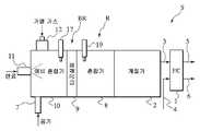
도 1에 있어서, 연료 개질형 연료 전지 시스템(S)은 양극(연료극: 도시 생략) 및 음극(산화제극: 도시 생략)을 구비하여, 연료 전지 본체를 형성하는 한 연료 전지(1), 연료 전지(1)에 공급되는 수소 농후 개질 가스를 생성하는 개질기(2), 개질기(2)로부터 연료 전지(1)에 개질 가스를 공급하는 개질 가스 공급 라인(3), 공기 압축기(도시 생략)로부터 연료 전지(1)에 공기를 공급하는 공기 공급 라인(4), 연료 전지(1)의 양극으로부터 배기 가스를 배출하는 양극 배기 가스 라인(5), 연료 전지(1)의 음극으로부터 배기 공기를 배출하는 음극 배기 가스 라인(6), 예비 혼합기(10)에 공기를 공급하는 공기 공급구(7), 예비 혼합기(10)에서 예비 혼합된 연료, 공기 등을 혼합시키는 혼합기(8), 예비 혼합기(10)와 혼합기(8) 사이에 배치되는 다공질체(9), 연료, 공기 등을 예비 혼합하는 예비 혼합기(10), 예비 혼합기(10)에 액체 연료를 분사하는 연료 공급 장치(11), 예비 혼합기(10)에 가열 가스를 도입하는 가열 가스 도입구(12), 예비 혼합기(10) 내의 가연성 가스를 착화하는 착화원 A(17) 및 혼합기(8) 내의 가연성 가스를 착화하는 착화원 B(19)로 이루어진다.In FIG. 1, the fuel reforming fuel cell system S includes a positive electrode (fuel electrode: not shown) and a negative electrode (oxidant electrode: not shown) to form a fuel cell body, and thus, the
즉, 예비 혼합기(10)와 혼합기(8) 사이에 다공질체(9)가 배치되고, 예비 혼합기(10), 다공질체(9) 및 혼합기(8)를 망라하는 영역은 연소기(BR)를 형성한다. 개질기(2)는 이러한 연소기의 하류에 위치되어 개질기(2)에 의해 생성된 수소 농후 개질 가스를 개질 가스 공급 라인(3)을 통하여 연료 전지(1)에 공급한다. 연소기(BR) 및 개질기(2)를 망라하는 영역은 연료 개질 장치(R)를 형성한다.That is, the porous body 9 is disposed between the
다공질체(9)는 발포체, 소결체, 세선 집합체 및 벌집 구조체 중의 적어도 1개를 포함하는 구조로 구성된다. 보다 구체적으로는, 다공질체(9)는 금속 폼 재료 또는 세라믹 폼 재료와 같은 발포체, 금속 또는 세라믹 분말로 이루어진 소결체, 스틸 울이나 기타 세선화한 금속을 적층 또는 압축 등의 수단에 의해 성형된 세선 집합체, 및 금속 재료로 이루어진 벌집 구조체 중의 적어도 1개를 포함한다.The porous body 9 is comprised from the structure containing at least 1 of a foam, a sintered compact, a thin wire assembly, and a honeycomb structure. More specifically, the porous body 9 is a fine wire molded by a means such as laminating or compressing a foam such as a metal foam material or a ceramic foam material, a sintered body made of metal or ceramic powder, steel wool or other thinned metal, or the like. At least one of an aggregate and a honeycomb structure made of a metallic material.
연료 공급 장치(11)로부터 예비 혼합기(10)에 공급되는 연료는 개질용 공급 연료에 해당하고, 이 목적을 위해 이용되고 있는 탄화수소 또는 물과 함께 수소를 포함한다.The fuel supplied from the
한편, 가열 가스는 가열 가스 도입구(12)로부터 공급되어, 예비 혼합기(10)에서 연료 및 공기가 혼합된다. 특히, 예비 혼합기(10)에 도입되는 가열 가스는 연료 전지(1)의 오프 가스를 연소함으로써 얻어지는 배기 가스(연소 가스) 또는 이러한 배기 가스와 열 교환되는 공기를 포함하는 고온 가스로 이루어져서, 예비 혼합기(10)에 도입되는 연료 및 공기에 열을 가한다. 물론, 고온 가스는 이러한 배기 가스 또는 공기뿐만 아니라, 연료 전지의 본질적으로 배기 가스 또는 오프 가스와 열 교환된 압축 가스를 포함한다.On the other hand, heating gas is supplied from the
한편, 연료가 액체 연료로 이루어지는 경우에 있어서, 가열 가스가 충분히 고온으로 유지되고, 예비 혼합기의 크기에 제한이 없다면, 그 자체로, 예비 혼합기는 연료 및 공기의 충분한 기화 및 혼합을 달성할 수 있다. 그렇지만, 이러한 구조에 있어서, 예비 혼합기의 크기가 필연적으로 증가하기 쉽고, 또한, 가스 확산 속도 때문에 균질한 혼합 가스를 얻는 데에 어려움을 직면한다.On the other hand, in the case where the fuel is made of a liquid fuel, if the heating gas is kept at a sufficiently high temperature and there is no limitation on the size of the premixer, the premixer can, by itself, achieve sufficient vaporization and mixing of the fuel and air. . However, in such a structure, the size of the premixer is likely to increase inevitably, and also faces difficulties in obtaining a homogeneous mixed gas due to the gas diffusion rate.
여기서, 본 출원 실시 형태는 연료 및 가열 가스가 예비 혼합기(10)에서 예비 혼합된다는 구조를 갖는다. 이러한 구조하에서, 액체 연료가 완전히 기화될 수 없더라도, 비기화 액체 연료는 즉시 다공질체(9)에 들어가서 기화된다. 이어서, 다공질체(9)에 의해 난류가 형성되어, 미리 예비 혼합된 혼합 가스의 확산을 촉진시키게 된다. 다음에, 다공질체(9)로부터 배출되는 연료 및 가열 가스를 포함하는 혼합 가스는 순차로 개질기(2)에 공급되는 균질한 혼합 가스를 형성한다. 즉, 다공질체(9)는 혼합 가스의 균질화 및 연료의 기화를 달성하는 기능을 갖고, 예비 혼합기(10)의 현저한 크기 감소를 달성할 수 있다.Here, the embodiment of the present application has a structure in which fuel and heating gas are premixed in the
다음에, 상기 기재된 구조로 본 출원 실시 형태의 개질형 연료 전지 시스템을 기동하는 운전 방법을 도 2를 참조하여 하기에 설명한다.Next, an operation method of starting the reforming fuel cell system of the presently filed embodiment with the above-described structure will be described below with reference to FIG. 2.
도 2는 본 출원 실시 형태의 개질형 연료 전지 시스템을 기동하는 운전 방법의 기본 순서를 나타내는 흐름도이다. 또한, 운전의 기본 순서는 연료 전지 시스템의 도시 생략의 제어기에 의해 실행된다.2 is a flowchart showing a basic procedure of a driving method for starting a reforming fuel cell system according to an embodiment of the present application. In addition, the basic procedure of operation is performed by the controller of omission of illustration of a fuel cell system.
우선, 단계 S1에 있어서, 일련의 단계가 기동하고, 가열 연소가 실시되어 다공질체(9)를 가열 및 워밍 업한다. 말하자면, 공기는 공기 공급구(7)로부터 예비 혼합기에 공급되고, 또한 액체 연료는 연료 공급 장치(11)로부터 예비 혼합기에 분사되어, 혼합 가스를 형성하고, 착화원 A(17)에 의해 예비 혼합기(10)에서 착화되어, 확산 연소를 개시함으로써 다공질체(9)를 가열한다. 연료를 기화시키는데 요구되는 온도가 300℃라고 가정하면, 확산 연소는 다공질체(9)가 300℃에 도달하기까지 지속되고, 온도가 300℃에 도달하는 시점에서, 연료 및 공기의 공급은 일단 정지되어, 예비 혼합기(10)에서의 확산 연소를 정지한다. 또한, 착화원 A(17)는 글루(glow) 플러그 또는 스파크 플러그를 포함할 수도 있다.First, in step S1, a series of steps are started, heat-burning is performed, and the porous body 9 is heated and warmed up. That is, air is supplied to the premixer from the
다음에, 단계 S2에 있어서, 다공질체(9) 및 혼합기(8)는 예비 증발 및 예비 혼합 연소를 달성하여 개질기(2)를 워밍 업한다. 즉, 액체 연료는 연료 공급 장치(11)로부터 예비 혼합기(10)에 분사되고, 또한 공기는 공기 공급구(7)를 통하여 예비 혼합기(10)에 공급되고, 고온 가열 가스는 가열 가스 도입구(12)를 통하여 도입된다. 공급되는 이러한 연료는 액체 연료이기 때문에, 액체 연료는 고온 가스인 가열 가스 및 다공질체(9)로부터 각각 열량을 빼앗아, 기화되어 다공질체(9)의 하류에서 균질한 혼합 가스를 생성한다. 다음에, 이 혼합 가스는 착화원 B(19)에 의해 착화됨으로써 혼합기(8) 내의 혼합 가스의 연소를 가능하게 한다. 또, 게다가, 이 연소 가스는 개질기(2)에 공급됨으로써 개질기(2)를 가열하고 워밍 업한다.Next, in step S2, the porous body 9 and the mixer 8 achieve preliminary evaporation and premixed combustion to warm up the
말하자면, 여기서, 연료 및 공기의 예비 혼합을 달성하면서 고온 가열 가스를 이에 작용시키는 예비 혼합기(10) 때문에, 다공질체(9)는 균질한 공기-연료 혼합을 얻을 수 있다. 다음에, 혼합 가스는 착화원 B(19)에 의해 착화되어, 연소 가스를 얻는다. 이러한 연소일 때, 균질 혼합 가스가 착화되고, 연소 온도에서 어떠한 불균일도 발생하지 않아 국소적으로 NOx의 형성을 야기할 수 있는 고온 증가를 피하기 때문에, 배기 가스 중의 NOx의 감소와 같은, 배기 가스 조성을 용이하게 제어할 수 있다는 유리한 특징을 갖는다. 또한, 착화원 B(19)는 착화원 A(17)와 마찬가지로, 글루 플러그 또는 스파크 플러그를 적용할 수 있다. 또한, 혼합기(8) 내에 또는 이의 바로 하류에 연소 화염의 형성을 방지하기 위해 부가적인 다공질체를 위치시킴으로써, 연소부와 개질기(2) 사이의 거리를 더욱 감소시킬 수 있다.In other words, here, because of the
특히, 개질기가 500℃에서 개질 반응을 성취하는 경우에 있어서, 상기 예비 증발 및 예비 혼합 연소는 개질 온도가 500℃에 도달하기까지 지속하고, 500℃의 온도에서, 연료 및 공기의 공급은 일단 정지되어 연소를 중지함으로써, 일련의 단계를 종지한다. 또한, 이후에, 정상 운전 모드로 운전이 진행된다.In particular, when the reformer achieves a reforming reaction at 500 ° C., the preliminary evaporation and premix combustion continue until the reforming temperature reaches 500 ° C., at a temperature of 500 ° C., the supply of fuel and air is once stopped And stops combustion, thereby ending the series of steps. Also, after that, the operation proceeds to the normal operation mode.
즉, 본 출원 실시 형태의 연료 전지 시스템에 있어서, 개질기(2)가 소정 온도에서 충분히 워밍 업된 후, 정상 운전 모드로 운전이 진행된다. 이러한 정상 운전 모드시에, 예비 혼합기(10) 내의 가열 가스 중에 연료를 공급하어, 연료를 예비 혼합기(10) 및 다공질체(9)에서 충분히 기화시킨 후, 개질기(2)에서 개질을 실시한다.That is, in the fuel cell system of the presently filed embodiment, after the
상기 개시된 연료 전지 시스템의 이러한 순서로 정상 운전을 개시할 때, 특히 다공질체(9) 및 개질기(2)의 기동 운전을 완료한 후, 다량의 질소 산화물을 생성하는 확산 연소를 최소화하면서, 동시적으로 신속하게 연료 전지 시스템의 워밍 업을 할 수 있게 된다.When starting the normal operation in this order of the fuel cell system disclosed above, in particular after completing the start-up operation of the porous body 9 and the
또, 연료가 액체 연료로 이루어지는 경우에 있어서, 연료 공급 장치(11)로서 연료 분사 밸브의 사용은 연료와 공기의 혼합을 용이하게 한다. 또한, 연료 공급 장치 및 공기 공급 장치를 조합시킨 2액체식 연료 분사 밸브가 채용되어도 되고, 이러한 경우에 있어서, 연료의 액적은 보다 미세하게 형성되어 공기와의 혼합 성능을 용이하게 한다. 향상된 비용 성능의 관점으로부터 글루 플러그 또는 스파크 플러그를 착화원 A(17) 및 착화원 B(19)로서 적용할 수도 있다.In the case where the fuel is made of liquid fuel, use of the fuel injection valve as the
상술의 본 출원 실시 형태에 있어서, 다공질체의 하류 영역에서 예비 증발 및 예비 혼합된 균질한 공기-연료 혼합을 달성하는 능력에 의해, 국소적으로 분포된 고온부 없이 예비 증발 및 예비 혼합 연소를 할 수 있으므로, 분사된 연료를 연소시키는 확산 연소시에 얻어지는 것보다 더 낮은 값으로 연소시에 발생하는 NOx 함량을 감소시킬 수 있다.In the above-described present application embodiment, by the ability to achieve pre-evaporation and pre-mixed homogeneous air-fuel mixing in the downstream region of the porous body, pre-evaporation and pre-mix combustion can be performed without a locally distributed hot portion. Therefore, the NOx content generated during combustion can be reduced to a lower value than that obtained during diffusion combustion of burning the injected fuel.
또, 예비 단계에서 확산 연소시에 다공질체를 가열하고 워밍 업한 후, 가열 가스 및 연료를 예비 혼합기에 공급하여 예비 증발 및 예비 혼합 연소의 운전을 진행하기 때문에, 예비 혼합기 및 다공질체는 연료 및 고온 가스의 예비 증발 및 예 비 혼합을 성취할 수 있어, 혼합기에서의 예비 증발 및 예비 혼합 연소에 즉시 이행시킬 수 있다.In addition, since the porous body is heated and warmed up during the diffusion combustion in the preliminary stage, the pre-evaporator and the porous body are fed to the fuel and the high temperature because the heating gas and the fuel are supplied to the premixer to operate the preliminary evaporation and the premixed combustion. Preliminary evaporation and preliminary mixing of the gas can be achieved, allowing immediate transition to preliminary evaporation and premixed combustion in the mixer.
또한, 개질기를 워밍 업할 때, 이러한 예비 증발 및 예비 혼합 연소가 발생하는 비율이 증가하기 때문에, 발생되는 NOx의 양을 제거할 수 있다.In addition, since the rate at which such preliminary evaporation and premixed combustion occurs when warming up the reformer increases, the amount of NOx generated can be removed.
게다가, 개질기를 워밍 업하는 연소기를, 연료 및 가열 가스를 혼합하거나, 연료, 가열 가스 및 공기를 기화 및 혼합하는 증발기로서 사용할 수 있기 때문에, 전체 연료 전지 시스템의 구성 부품의 수를 축소할 수 있다.In addition, since the combustor warming up the reformer can be used as an evaporator for mixing fuel and heating gas or for vaporizing and mixing fuel, heating gas and air, the number of components of the entire fuel cell system can be reduced. .
(제2 실시 형태)(2nd embodiment)
다음에, 본 발명에 따른 제2 실시 형태의 연료 개질 장치, 연료 전지 시스템 및 관련 방법을 주로 도 3을 참조하여 자세하게 설명한다.Next, the fuel reforming apparatus, the fuel cell system, and the related method of the second embodiment according to the present invention will be described in detail mainly with reference to FIG.
도 3은 본 출원 실시 형태의 연소기 및 연료 개질 장치를 구비한 연료 전지 시스템의 구조를 도시하는 도면이다.3 is a diagram illustrating a structure of a fuel cell system including a combustor and a fuel reforming device of the presently filed embodiment.
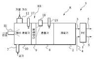
도 3에 있어서, 본 출원 실시 형태와 제1 실시 형태 사이의 차이점은 연료 전지(1)의 하류 단계에 배치되어 연료 전지(1)로부터 배출된 배기 가스를 연소하는 제2 연소기(13), 연소기(13)에서 연소된 연소 가스를 예비 혼합기(10)의 가열 가스 도입구(12)에 인도하는 연소 가스 순환 라인(14), 및 연소기(13)로부터 외부로 연소 가스를 배출하는 연소 배기 가스 라인(15)을 추가로 포함하는 구조에 있다. 본 출원 실시 형태의 그 밖의 구조는 제1 실시 형태와 마찬가지이므로, 동일한 참조 부호가 부여된 동일한 요소의 장황한 설명을 생략했다. 또한, 본 출원 실시 형태의 연료 전지 시스템의 기동 방법은 제1 실시 형태의 그것과 마찬가지이다.In FIG. 3, the difference between the presently applied embodiment and the first embodiment is that a
특히, 본 출원 실시 형태는 가열 가스로서 연료 전지(1)로부터 배기된 잔류 수소를 포함하는 연소 가스를 이용하는 구조의 형태를 취한다. 연료 전지(1) 및 연소기(13)는 양극 배기 가스 라인(5) 및 음극 배기 가스 라인(6)을 통하여 서로 접속되고, 양극 배기 가스(오프 가스) 및 음극 배기 가스(오프 가스)는 각각의 라인을 통하여 연소기에 공급된다. 여기서, 일반적으로, 연료 전지가 양극에 공급된 수소 전체량을 산화시키는 것은 어려우므로, 양극 배기 가스는 연료 전지에서 이용되지 않은 수소 및 수증기를 포함한다. 따라서, 연소기(13)는 양극 배기 가스에 포함된 수소 및 음극 배기 가스에 포함된 산소를 연소시킬 수 있어, 연소 가스를 가열 가스로서 형성되게 할 수 있다. 또, 이러한 연소기(13)로부터 배출된 연소 배기 가스의 적어도 일부분을 연소 가스 순환 라인(14)을 통하여 가열 가스 도입구(12)로부터 예비 혼합기(10)에 도입한다. 또한, 잔류 연소 가스를 연소 배기 가스 라인(15)을 통하여 배출한다.In particular, the presently filed embodiment takes the form of a structure using a combustion gas containing residual hydrogen exhausted from the
상기 개시된 본 출원 실시 형태에 의하면, 배기 가스 중의 수소를 연소시켜서, 가열 가스를 얻음으로써, 가열 가스를 생성하기 위한 외부 에너지에 대한 필요가 없으므로, 연료 전지 시스템의 효율을 향상시킬 수 있게 된다.According to the above-described disclosed application embodiment, by burning hydrogen in exhaust gas to obtain a heating gas, there is no need for external energy to generate heating gas, thereby improving the efficiency of the fuel cell system.
또, 개질기에 의해 수증기 개질이 실시될 때, 배기 가스는 수분을 포함하여, 수증기 개질을 위해 개질기에 이러한 수분을 공급할 수 있다.In addition, when steam reforming is carried out by the reformer, the exhaust gas may include moisture, and may supply such moisture to the reformer for steam reforming.
(제3 실시 형태)(Third embodiment)
다음에, 본 발명에 따른 제3 실시 형태의 연소기, 연료 개질 장치, 연료 전지 시스템 및 관련 방법을 주로 도 4를 참조하여 자세하게 설명한다.Next, the combustor, the fuel reforming apparatus, the fuel cell system, and the related method of the third embodiment according to the present invention will be described in detail mainly with reference to FIG.
도 4는 본 출원 실시 형태의 연소기 및 연료 개질 장치를 구비한 연료 전지 시스템의 구조를 도시하는 도면이다.4 is a diagram illustrating a structure of a fuel cell system including a combustor and a fuel reforming device of the presently filed embodiment.
도 4에 있어서, 본 출원 실시 형태와 제1 실시 형태 사이의 차이점은 연료 전지(1)로부터 배출된 배기 가스를 연소하기 위해, 연료 전지(1)의 하류 단계에 배치되는 제2 연소기(13), 연소기(13)의 하류 단계에 배치된 연소 배기 가스 라인(15), 연소 배기 가스와 공기 사이에 열 교환하는 열 교환기(16), 및 열 교환기(16)에서 가열되는 공기를 가열 가스 도입구(12)에 인도하는 가열 가스 라인(20)을 부가적으로 포함하는 구조에 있고, 열 교환기(16)에서 가열된 공기는 순차로 가열 가스로서 예비 혼합기(10)에 도입된다. 또한, 가열 가스는 가열된 공기로 이루어지기 때문에, 예비 혼합기(10)는 도 1에 도시된 바와 같은 공기 공급구(7)를 갖지 않는다. 본 출원 실시 형태의 그 밖의 구조는 제1 실시 형태와 마찬가지이므로, 동일한 참조 부호가 부여된 동일한 요소의 장황한 설명을 생략했다. 또한, 본 출원 실시 형태의 연료 전지 시스템의 기동 방법은 제1 실시 형태의 그것과 마찬가지이다.In FIG. 4, the difference between the presently applied embodiment and the first embodiment is that the
특히, 본 출원 실시 형태는 개질 반응용 수증기를 필수적으로 필요로 하지 않고, 가열 가스로서 가열된 공기가 이용되는 구조의 형태를 취한다. 연료 전지(1) 및 연소기(13)는 양극 배기 가스 라인(5) 및 음극 배기 가스 라인(6)을 통하여 서로 접속되고, 양극 배기 가스(오프 가스) 및 음극 배기 가스(오프 가스)는 각각의 라인을 통하여 연소기(13)에 공급된다. 연소기(13)는 양극 배기 가스에 포함된 수소 및 음극 배기 가스에 포함된 산소를 연소함으로써, 연소 배기 가스 라인(15)을 통하여 연소 가스를 열 교환기(16)에 도입한다. 열 교환기(16)에 있어서, 연소 배기 가스와 공기 사이에 열 교환을 하여 공기를 가열한다. 다음에, 가열 가스 라인(20)을 통하여 가열 가스 도입구(12)로부터 예비 혼합기(10)에 이러한 가열된 공기를 도입한다. 한편, 열 교환에 사용된 연소 가스는 연소 배기 가스 라인(15')을 통하여 배기된다.In particular, the presently filed embodiment does not necessarily require steam for reforming reaction, and takes the form of a structure in which heated air is used as the heating gas. The
상기 개시된 본 출원 실시 형태에 의하면, 공기를 가열 가스로서 사용하여, 개질기에 공급되고 있는 연소 가스 중의 과잉 성분을 회피할 수 있다.According to this disclosed application embodiment, it is possible to avoid excess components in the combustion gas supplied to the reformer by using air as the heating gas.
또, 수증기를 전혀 필요로 하지 않는 개질기의 경우에 있어서, 물론, 개질을 위해 배기 가스 중에 포함된 수분을 공급하는 것을 생략해도 된다.Moreover, in the case of the reformer which does not require any water vapor, of course, supplying the water contained in the exhaust gas for reforming may be omitted.
(제4 실시 형태)(4th embodiment)
다음에, 본 발명에 따른 제4 실시 형태의 연소기, 연료 개질 장치, 연료 전지 시스템 및 관련 방법은 주로 도 5를 참조하여 설명한다.Next, the combustor, the fuel reforming apparatus, the fuel cell system, and the related method of the fourth embodiment according to the present invention will be mainly described with reference to FIG.
도 5는 본 출원 실시 형태의 연소기 및 연료 개질 장치를 구비한 연료 전지 시스템의 구조를 도시하는 도면이다.5 is a diagram illustrating a structure of a fuel cell system including a combustor and a fuel reforming device of the presently filed embodiment.
도 5에 있어서, 본 출원 실시 형태와 제1 실시 형태 사이의 차이점은 개질기(2)가 일반적으로 수증기 개질을 실시하는 구조의 형태를 취하고, 혼합기(8)가 다공질체(9)에 대해 물을 분사하는 물 공급 장치(18)를 구비한다는 것에 있다. 따라서, 연료 개질 장치(R)는 다공질체(9)에 의해 효과적으로 물을 증발시킬 수 있어, 수증기 개질에 요구되는 수증기를 공급시키도록 구성된다고 말하여지고 있다. 그 밖의 구조는 제1 실시 형태와 마찬가지이므로, 동일한 참조 부호가 부여된 동일 한 요소의 장황한 설명을 생략했다. 또한, 본 출원 실시 형태의 연료 전지 시스템의 기동 방법은 제1 실시 형태의 그것과 마찬가지이다.In FIG. 5, the difference between the presently filed embodiment and the first embodiment is that the
특히, 본 출원 실시 형태에 있어서, 연료는 예비 혼합기(10)에서 연소되고, 이의 얻어진 연소 열량은 물 공급 장치(18)로부터 분사된 물을 기화하는데 이용한다. 물을 기화하기 위해서, 표면적을 증가시켜서 기화 속도를 빠르게 하는 것이 유용하다. 그 때문에. 상기 물 공급은 다공질체(9)에 대해 분무 형태로 실시된다. 다공질체(9)의 표면 상에 튀긴 물이 존재하더라도, 다공질체(9)는 연소를 통하여 가열되기 때문에, 상기 물은 다공질체(9)의 표면 상에서 충분히 증발되어 기화되기 쉽다.In particular, in the presently filed embodiment, the fuel is combusted in the
또, 예비 혼합기(10)에서 연소를 이론적 공기 연료 혼합보다 높은 연료 농후 영역에서 달성함으로써, 연료 증기를 또한 생성할 수 있다. 따라서, 연료 증기, 다공질체(9)에 의해 생성된 수증기, 및 부가적으로 공기 공급구(7)로부터 공급된 공기를 혼합함으로써, 수증기 개질에 요구되는 혼합 가스를 개질기(2)에 공급할 수 있다. 물론, 공기가 개질기(2)에 도입되기 전에 혼합 가스 중에서 혼합되기 때문에, 이러한 수증기 개질은 수증기 개질 반응 및 부분 산화 반응을 채용하는 오토 서멀 반응일 수도 있다.In addition, by achieving combustion in the
또한, 정상 운전 모드로 개질 반응이 연소 가스 중의 수증기를 이용하는 수증기 개질 반응을 취하는 경우에 있어서, 연료 전지 시스템의 정지 후에 수증기를 신속히 공급할 수 없더라도, 개질기를 수증기 개질에 요구되는 온도로 유지한다면, 본 출원 실시 형태에서의 정상 운전 모드에 의해 개질기를 신속히 기동하는 것을 가능하게 한다.In addition, in the case where the reforming reaction takes the steam reforming reaction using steam in the combustion gas in the normal operation mode, even if the steam cannot be rapidly supplied after the stop of the fuel cell system, the reformer is maintained at the temperature required for steam reforming. The normal operation mode in the filing embodiment makes it possible to quickly start the reformer.
상기 개시된 본 출원 실시 형태에 의하면, 수증기 개질을 달성하는 개질기의 경우에 있어서, 물을 수증기 개질을 위해 개질기에 충분히 공급할 수 있다. 따라서, 개질기를 연속적으로 운전하고, 개질기를 단기간 정지한 후에 개질기를 다시 기동하는 경우와 같이 개질기를 고온으로 유지하는 상황하에서 개질기를 신속히 기동하는 것이 가능해진다.According to the presently disclosed embodiment, in the case of the reformer which achieves steam reforming, water can be sufficiently supplied to the reformer for steam reforming. Therefore, it is possible to start the reformer quickly in a situation in which the reformer is kept at a high temperature such as when the reformer is continuously operated and the reformer is restarted after a short period of time.
또한, 예비 혼합기에서 연소를 이론적 공기 연료 혼합보다 연료가 보다 농후한 연료 농후 측에서 실시하여, 얻어진 연소열에 의해 물을 수증기로 기화시켜 혼합 가스 중에 혼합하고, 이 혼합 가스를 개질기에 공급하는 경우에 있어서, 공급되는 가스는 연료 증기 및 수증기를 포함하고 있기 때문에, 이들 가스를 수증기 개질 반응에 이용할 수 있다.In the case where combustion is performed in a premixer on the fuel rich side where the fuel is richer than the theoretical air fuel mixing, vaporization of water into steam by the heat of combustion obtained, mixing in the mixed gas, and supplying the mixed gas to the reformer Since the gas to be supplied contains fuel vapor and steam, these gases can be used for the steam reforming reaction.
또한, 개질기에 도입되기 전에 혼합 가스 중에 혼합된 공기의 존재에 의해, 오토 서멀 반응에 또한 이용할 수 있다.In addition, due to the presence of air mixed in the mixed gas before being introduced into the reformer, it can also be used for the auto thermal reaction.
(제5 실시 형태)(5th embodiment)
다음에, 본 발명에 따른 제5 실시 형태의 연소기, 연료 개질 장치, 연료 전지 시스템 및 관련 방법은 주로 도 6을 참조하여 설명한다.Next, the combustor, the fuel reforming apparatus, the fuel cell system, and the related method of the fifth embodiment according to the present invention will be mainly described with reference to FIG.
도 6은 본 출원 실시 형태의 연소기 및 연료 개질 장치를 구비한 연료 전지 시스템의 구조를 도시하는 도면이다.FIG. 6 is a diagram illustrating a structure of a fuel cell system including a combustor and a fuel reforming device of the presently filed embodiment.
도 6에 있어서, 본 출원 실시 형태와 제1 실시 형태 사이의 차이점은 혼합기(8)로부터 가열 가스 도입구(12)에 연소 가스를 도입하는 연소 가스 순환 라인(14')을 부가적으로 포함하는 구조에 있다. 그 밖의 구조는 제1 실시 형태와 마찬가지이므로, 동일한 참조 부호가 부여된 동일한 요소의 장황한 설명을 생략했다. 또한, 본 출원 실시 형태의 연료 전지 시스템의 기동 방법은 제1 실시 형태의 그것과 마찬가지이다.In FIG. 6, the difference between the presently filed embodiment and the first embodiment further comprises a combustion
특히, 본 출원 실시 형태에 있어서, 혼합기(8)로부터 배출된 연소 가스의 일부는 연소 가스 순환 라인(14')을 통하여 가열 가스로서 예비 혼합기(10)에 도입되고, 얻어진 열량은 다공질체(9)에 의해 연료의 기화에 이용되어 혼합 가스를 얻는다.In particular, in the presently filed embodiment, a part of the combustion gas discharged from the mixer 8 is introduced into the
상기 개시된 본 출원 실시 형태에 의하면, 혼합기에서 생성된 연소 가스의 일부를 가열 가스로서 사용함으로써, 새로운 가열 장치의 사용 없이, 단순 구조에 의해 가열 가스를 공급하는 것을 가능하게 실현할 수 있다.According to the above-described disclosed application embodiment, by using a part of the combustion gas generated in the mixer as the heating gas, it is possible to realize that the heating gas can be supplied by a simple structure without using a new heating device.
2002년 6월 3일 출원의 일본국 특원 2002-161629호의 전체 내용은 본 명세서에 참조로서 포함된다.The entire contents of Japanese Patent Application No. 2002-161629, filed June 3, 2002, are incorporated herein by reference.
본 발명은 특정의 실시 형태를 참조하여 상술되었지만, 상술의 실시 형태에 제한되는 것은 아니다. 당업자에 의해 교시를 고려하여 상술의 실시 형태의 변화 및 변경이 실시될 수도 있다. 본 발명의 범위는 하기의 청구항을 참고하여 정의된다.Although the present invention has been described above with reference to specific embodiments, it is not limited to the above embodiments. Changes and variations of the embodiments described above may be practiced by those skilled in the art in view of the teachings. The scope of the invention is defined with reference to the following claims.
상술한 바와 같이, 연소기는 연료 및 가열 가스를 혼합하는 예비 혼합기, 상기 예비 혼합기에서 혼합된 연료 및 가열 가스를 연소하는 혼합기, 및 상기 예비 혼합기와 상기 혼합기 사이에 배치된 다공질체를 구비한다. 여기서, 상기 개질기는 상기 연소기의 하류에 배치될 수 있어, 상기 연소기 및 상기 개질기는 연료 개질 장치를 형성한다. 또한, 연료 전지는 상기 개질기의 하류에 배치될 수 있어, 상기 연료 개질 장치를 구비한 연료 전지 시스템을 형성한다. 이러한 구조에 의해, 질소 산화물의 생성을 억제할 수 있다. 따라서, 다공질체를 포함하는 연소기, 연료 개질 장치 및 연료 전지 시스템은 연료 전지 동력 차량 및 산업용 또는 가정용 발전기에 적용될 수 있어, 광범위한 이러한 적용이 기대된다.As described above, the combustor includes a premixer for mixing fuel and heating gas, a mixer for burning fuel and heating gas mixed in the premixer, and a porous body disposed between the premixer and the mixer. Here, the reformer may be disposed downstream of the combustor such that the combustor and the reformer form a fuel reformer. In addition, a fuel cell may be disposed downstream of the reformer to form a fuel cell system with the fuel reformer. By this structure, generation | occurrence | production of nitrogen oxide can be suppressed. Accordingly, combustors, fuel reformers, and fuel cell systems comprising porous materials can be applied to fuel cell powered vehicles and industrial or domestic generators, and a wide range of such applications are expected.
Claims (20)
Translated fromKoreanApplications Claiming Priority (3)
| Application Number | Priority Date | Filing Date | Title |
|---|---|---|---|
| JP2002161629AJP2004011933A (en) | 2002-06-03 | 2002-06-03 | Combustor, fuel reformer, and fuel cell system |
| JPJP-P-2002-00161629 | 2002-06-03 | ||
| PCT/JP2003/006767WO2003101890A1 (en) | 2002-06-03 | 2003-05-29 | Combustor, fuel reforming device, fuel cell system and method for starting up the fuel reforming system |
Publications (2)
| Publication Number | Publication Date |
|---|---|
| KR20040044550A KR20040044550A (en) | 2004-05-28 |
| KR100599885B1true KR100599885B1 (en) | 2006-07-12 |
Family
ID=29706583
Family Applications (1)
| Application Number | Title | Priority Date | Filing Date |
|---|---|---|---|
| KR1020047005393AExpired - Fee RelatedKR100599885B1 (en) | 2002-06-03 | 2003-05-29 | How to Start a Combustor, Fuel Reformer, Fuel Cell System, and Fuel Reformer System |
Country Status (6)
| Country | Link |
|---|---|
| US (1) | US20050019623A1 (en) |
| EP (1) | EP1509475A1 (en) |
| JP (1) | JP2004011933A (en) |
| KR (1) | KR100599885B1 (en) |
| CN (1) | CN1284722C (en) |
| WO (1) | WO2003101890A1 (en) |
Families Citing this family (39)
| Publication number | Priority date | Publication date | Assignee | Title |
|---|---|---|---|---|
| JP4655464B2 (en) | 2003-09-24 | 2011-03-23 | 日産自動車株式会社 | Fuel reformer |
| DE10348638A1 (en)* | 2003-10-15 | 2005-05-25 | J. Eberspächer GmbH & Co. KG | An evaporator assembly for producing a hydrocarbon / steam mixture decomposable in a hydrogen recovery reformer |
| DE102004049903B4 (en)* | 2004-10-13 | 2008-04-17 | Enerday Gmbh | Burner device with a porous body |
| US7632322B2 (en)* | 2005-06-07 | 2009-12-15 | Idatech, Llc | Hydrogen-producing fuel processing assemblies, heating assemblies, and methods of operating the same |
| KR100616685B1 (en)* | 2005-06-09 | 2006-08-28 | 삼성전기주식회사 | Small reformer and its manufacturing method |
| KR100707599B1 (en) | 2005-06-24 | 2007-04-13 | 삼성에스디아이 주식회사 | Fuel mixing tank and fuel cell device having same |
| DE102005034941B4 (en)* | 2005-07-22 | 2008-12-18 | J. Eberspächer GmbH & Co. KG | Reformer for the production of synthesis gas |
| CN100406802C (en)* | 2006-01-20 | 2008-07-30 | 东北大学 | A porous metal-ceramic medium gas fuel burner |
| US7629067B2 (en)* | 2006-05-22 | 2009-12-08 | Idatech, Llc | Hydrogen-producing fuel processing systems and fuel cell systems with a liquid leak detection system |
| DE102006063063B3 (en) | 2006-06-01 | 2021-12-30 | Faurecia Emissions Control Technologies, Germany Gmbh | Assembly for generating a hydrogen-containing gas |
| AT502131B1 (en)* | 2006-10-03 | 2008-02-15 | Avl List Gmbh | Energy generation unit for use as power train support unit in automotive vehicle, has flame burner with combustion chamber connected to outgoing line at cathode side of high-temperature fuel cell |
| DE102006048984A1 (en)* | 2006-10-17 | 2008-04-24 | Enerday Gmbh | Use of a burner device in a fuel cell system |
| EP2127009B1 (en)* | 2007-01-22 | 2019-05-08 | LG Fuel Cell Systems Inc. | Multistage combustor and method for starting a fuel cell system |
| US20080268300A1 (en)* | 2007-04-30 | 2008-10-30 | Pfefferle William C | Method for producing fuel and power from a methane hydrate bed using a fuel cell |
| DE102007053487A1 (en)* | 2007-11-09 | 2009-05-14 | J. Eberspächer GmbH & Co. KG | Fuel-powered heating device, in particular for camping vehicles |
| CN101494294B (en)* | 2008-01-23 | 2011-09-14 | 中国科学院宁波材料技术与工程研究所 | Catalytic reforming plant for solid-oxide fuel battery |
| CN101832554B (en)* | 2010-05-18 | 2011-10-05 | 杭州电子科技大学 | A liquid fuel porous medium combustion device and its combustion method |
| CN102692017B (en)* | 2011-03-25 | 2015-03-18 | 中国科学院宁波材料技术与工程研究所 | Solid-oxide fuel cell (SOFC) power generation system and burner thereof |
| DE102011087971B4 (en) | 2011-12-08 | 2021-03-04 | Eberspächer Climate Control Systems GmbH | Method for operating a heater that can be operated with hydrocarbon fuel |
| CN104112866B (en)* | 2013-04-19 | 2016-12-28 | 中国科学院宁波材料技术与工程研究所 | The burning of a kind of fuel cell system is reformed and is premixed integrated apparatus |
| US9774050B2 (en)* | 2013-07-18 | 2017-09-26 | Watt Fuel Cell Corp. | Apparatus and methods for mixing reformable fuels and an oxygen-containing gas and/or steam |
| US10233552B2 (en)* | 2013-08-22 | 2019-03-19 | 0798465 B.C. Ltd. | Apparatus and method for feeding a multi-phase mixture of reactants to an electrochemical reactor |
| US9687773B2 (en) | 2014-04-30 | 2017-06-27 | Honeywell International Inc. | Fuel deoxygenation and fuel tank inerting system and method |
| US9656187B2 (en) | 2014-11-12 | 2017-05-23 | Honeywell International Inc. | Fuel deoxygenation system contactor-separator |
| US9834315B2 (en) | 2014-12-15 | 2017-12-05 | Honeywell International Inc. | Aircraft fuel deoxygenation system |
| US9897054B2 (en) | 2015-01-15 | 2018-02-20 | Honeywell International Inc. | Centrifugal fuel pump with variable pressure control |
| WO2017065038A1 (en)* | 2015-10-16 | 2017-04-20 | 寛治 泉 | Engine system performing continuous combustion of oxygen and oxygen-enriched air |
| WO2017172390A1 (en)* | 2016-03-30 | 2017-10-05 | 3M Innovative Properties Company | Oxy-pyrohydrolysis system and method for total halogen analysis |
| JP6748802B2 (en)* | 2016-07-31 | 2020-09-02 | 寛治 泉 | An engine system that continuously burns hydrogen and enriched oxygen air. |
| CN108232252B (en)* | 2016-12-15 | 2020-02-21 | 中国科学院大连化学物理研究所 | A catalytic burner and its application |
| CN109681864B (en)* | 2019-01-10 | 2020-08-21 | 浙江大学 | Fuel combustion device and method based on fuel multi-effect pretreatment and flameless combustion |
| JP7445416B2 (en)* | 2019-12-02 | 2024-03-07 | 日産自動車株式会社 | Control method for fuel cell system and fuel cell system |
| JP7380300B2 (en)* | 2020-02-18 | 2023-11-15 | 株式会社豊田自動織機 | Combustor, reformer and reforming system |
| CN111370735B (en)* | 2020-03-19 | 2021-07-02 | 浙江锋源氢能科技有限公司 | A fuel cell humidification system |
| CN114699944B (en)* | 2022-02-18 | 2023-05-23 | 潍柴动力股份有限公司 | Steel wool mixer and diesel engine tail gas aftertreatment device with same |
| CN115342347A (en)* | 2022-07-29 | 2022-11-15 | 嵊州市浙江工业大学创新研究院 | A hydrogen-doped natural gas premixed porous swirl combustion system and its process method |
| CN115621491A (en)* | 2022-09-07 | 2023-01-17 | 浙江氢邦科技有限公司 | A multifunctional burner for solid oxide fuel cell system |
| KR102772220B1 (en)* | 2024-07-05 | 2025-02-26 | 프리텍코리아 주식회사 | Heater for the field heating asphalt recycling packing apparatus |
| CN119034616B (en)* | 2024-09-06 | 2025-09-19 | 重庆大学 | Fuel autothermal reforming reaction system and method suitable for extreme combustion conditions |
Family Cites Families (6)
| Publication number | Priority date | Publication date | Assignee | Title |
|---|---|---|---|---|
| NL7314826A (en)* | 1972-12-11 | 1974-06-13 | ||
| DE2614670A1 (en)* | 1976-04-05 | 1977-10-13 | Siemens Ag | GAS GENERATOR FOR THE CATALYTIC CONVERSION OF LIQUID, HYDROCARBON-CONTAINING FUEL WITH AN OXYGEN-CONTAINING GAS AT INCREASED TEMPERATURE INTO A FUEL GAS, IN PARTICULAR FROM FUEL FUEL |
| DE2723685A1 (en)* | 1977-05-25 | 1978-11-30 | Siemens Ag | Cracked gas generator for catalytic fuel gasification - with atomised fuel sprays on porous plate upstream of catalyst package |
| JP3572395B2 (en)* | 2000-02-18 | 2004-09-29 | 日産自動車株式会社 | Combustor for fuel reformer |
| JP3885479B2 (en)* | 2000-10-12 | 2007-02-21 | 日産自動車株式会社 | Fuel cell reformer |
| DE10060371A1 (en)* | 2000-12-05 | 2002-06-20 | Emitec Emissionstechnologie | Partial oxidation reactor |
- 2002
- 2002-06-03JPJP2002161629Apatent/JP2004011933A/enactivePending
- 2003
- 2003-05-29USUS10/493,243patent/US20050019623A1/ennot_activeAbandoned
- 2003-05-29CNCNB038012960Apatent/CN1284722C/ennot_activeExpired - Fee Related
- 2003-05-29WOPCT/JP2003/006767patent/WO2003101890A1/ennot_activeApplication Discontinuation
- 2003-05-29KRKR1020047005393Apatent/KR100599885B1/ennot_activeExpired - Fee Related
- 2003-05-29EPEP03733162Apatent/EP1509475A1/ennot_activeWithdrawn
Also Published As
| Publication number | Publication date |
|---|---|
| CN1568286A (en) | 2005-01-19 |
| WO2003101890A1 (en) | 2003-12-11 |
| US20050019623A1 (en) | 2005-01-27 |
| KR20040044550A (en) | 2004-05-28 |
| EP1509475A1 (en) | 2005-03-02 |
| CN1284722C (en) | 2006-11-15 |
| JP2004011933A (en) | 2004-01-15 |
Similar Documents
| Publication | Publication Date | Title |
|---|---|---|
| KR100599885B1 (en) | How to Start a Combustor, Fuel Reformer, Fuel Cell System, and Fuel Reformer System | |
| US7037349B2 (en) | Method and apparatus for fuel/air preparation in a fuel cell | |
| US5207185A (en) | Emissions reduction system for internal combustion engines | |
| US7736399B2 (en) | Electrically-heated metal vaporizer for fuel/air preparation in a hydrocarbon reformer assembly | |
| EP2127009B1 (en) | Multistage combustor and method for starting a fuel cell system | |
| US6929785B2 (en) | Method and apparatus for preheating of a fuel cell micro-reformer | |
| US20060037308A1 (en) | Fuel vaporizing device | |
| KR100463216B1 (en) | Fuel cell drive system | |
| JP2002305012A (en) | Fuel cell system | |
| KR20040032784A (en) | Hydrogen generator and electric generator using the same | |
| JP3398862B2 (en) | How to warm up the fuel evaporator | |
| JP2013521461A (en) | Equipment for providing hot exhaust gases | |
| CN101573289A (en) | Reformer, and method for reacting fuel and oxidant to gaseous reformate | |
| US20080253938A1 (en) | Method and apparatus for vaporizing fuel in a hydrocarbon reformer assembly | |
| JP3804436B2 (en) | Reformer | |
| JP3632590B2 (en) | Fuel cell system | |
| JP2003238109A (en) | Fuel processing device and method of starting the same | |
| JP3918915B2 (en) | Fuel heating device and fuel processing device using the same | |
| US7547333B2 (en) | Fuel reforming system | |
| JP2004018275A (en) | Fuel mixer for reformer | |
| GB2621338A (en) | Fuel cell system and method of operating the same | |
| CN115000473A (en) | Universal liquid fuel reformer system |
Legal Events
| Date | Code | Title | Description |
|---|---|---|---|
| A201 | Request for examination | ||
| PA0105 | International application | St.27 status event code:A-0-1-A10-A15-nap-PA0105 | |
| PA0201 | Request for examination | St.27 status event code:A-1-2-D10-D11-exm-PA0201 | |
| P11-X000 | Amendment of application requested | St.27 status event code:A-2-2-P10-P11-nap-X000 | |
| P13-X000 | Application amended | St.27 status event code:A-2-2-P10-P13-nap-X000 | |
| PG1501 | Laying open of application | St.27 status event code:A-1-1-Q10-Q12-nap-PG1501 | |
| E902 | Notification of reason for refusal | ||
| PE0902 | Notice of grounds for rejection | St.27 status event code:A-1-2-D10-D21-exm-PE0902 | |
| T11-X000 | Administrative time limit extension requested | St.27 status event code:U-3-3-T10-T11-oth-X000 | |
| E13-X000 | Pre-grant limitation requested | St.27 status event code:A-2-3-E10-E13-lim-X000 | |
| P11-X000 | Amendment of application requested | St.27 status event code:A-2-2-P10-P11-nap-X000 | |
| P13-X000 | Application amended | St.27 status event code:A-2-2-P10-P13-nap-X000 | |
| PN2301 | Change of applicant | St.27 status event code:A-3-3-R10-R13-asn-PN2301 St.27 status event code:A-3-3-R10-R11-asn-PN2301 | |
| E701 | Decision to grant or registration of patent right | ||
| PE0701 | Decision of registration | St.27 status event code:A-1-2-D10-D22-exm-PE0701 | |
| GRNT | Written decision to grant | ||
| PR0701 | Registration of establishment | St.27 status event code:A-2-4-F10-F11-exm-PR0701 | |
| PR1002 | Payment of registration fee | St.27 status event code:A-2-2-U10-U12-oth-PR1002 Fee payment year number:1 | |
| PG1601 | Publication of registration | St.27 status event code:A-4-4-Q10-Q13-nap-PG1601 | |
| PN2301 | Change of applicant | St.27 status event code:A-5-5-R10-R13-asn-PN2301 St.27 status event code:A-5-5-R10-R11-asn-PN2301 | |
| LAPS | Lapse due to unpaid annual fee | ||
| PC1903 | Unpaid annual fee | St.27 status event code:A-4-4-U10-U13-oth-PC1903 Not in force date:20090706 Payment event data comment text:Termination Category : DEFAULT_OF_REGISTRATION_FEE | |
| PC1903 | Unpaid annual fee | St.27 status event code:N-4-6-H10-H13-oth-PC1903 Ip right cessation event data comment text:Termination Category : DEFAULT_OF_REGISTRATION_FEE Not in force date:20090706 |