KR100597581B1 - Symmetrical Multiband Internal Antenna with Stubs - Google Patents
Symmetrical Multiband Internal Antenna with StubsDownload PDFInfo
- Publication number
- KR100597581B1 KR100597581B1KR1020040089854AKR20040089854AKR100597581B1KR 100597581 B1KR100597581 B1KR 100597581B1KR 1020040089854 AKR1020040089854 AKR 1020040089854AKR 20040089854 AKR20040089854 AKR 20040089854AKR 100597581 B1KR100597581 B1KR 100597581B1
- Authority
- KR
- South Korea
- Prior art keywords
- patch
- antenna
- stub
- internal antenna
- present
- Prior art date
- Legal status (The legal status is an assumption and is not a legal conclusion. Google has not performed a legal analysis and makes no representation as to the accuracy of the status listed.)
- Expired - Fee Related
Links
Images


Classifications
- H—ELECTRICITY
- H01—ELECTRIC ELEMENTS
- H01Q—ANTENNAS, i.e. RADIO AERIALS
- H01Q13/00—Waveguide horns or mouths; Slot antennas; Leaky-waveguide antennas; Equivalent structures causing radiation along the transmission path of a guided wave
- H01Q13/08—Radiating ends of two-conductor microwave transmission lines, e.g. of coaxial lines, of microstrip lines
- H—ELECTRICITY
- H01—ELECTRIC ELEMENTS
- H01Q—ANTENNAS, i.e. RADIO AERIALS
- H01Q9/00—Electrically-short antennas having dimensions not more than twice the operating wavelength and consisting of conductive active radiating elements
- H01Q9/04—Resonant antennas
- H01Q9/0407—Substantially flat resonant element parallel to ground plane, e.g. patch antenna
- H01Q9/0421—Substantially flat resonant element parallel to ground plane, e.g. patch antenna with a shorting wall or a shorting pin at one end of the element
- H—ELECTRICITY
- H01—ELECTRIC ELEMENTS
- H01Q—ANTENNAS, i.e. RADIO AERIALS
- H01Q5/00—Arrangements for simultaneous operation of antennas on two or more different wavebands, e.g. dual-band or multi-band arrangements
- H01Q5/30—Arrangements for providing operation on different wavebands
- H01Q5/307—Individual or coupled radiating elements, each element being fed in an unspecified way
- H01Q5/342—Individual or coupled radiating elements, each element being fed in an unspecified way for different propagation modes
- H01Q5/357—Individual or coupled radiating elements, each element being fed in an unspecified way for different propagation modes using a single feed point
- H—ELECTRICITY
- H01—ELECTRIC ELEMENTS
- H01Q—ANTENNAS, i.e. RADIO AERIALS
- H01Q7/00—Loop antennas with a substantially uniform current distribution around the loop and having a directional radiation pattern in a plane perpendicular to the plane of the loop
- H—ELECTRICITY
- H01—ELECTRIC ELEMENTS
- H01Q—ANTENNAS, i.e. RADIO AERIALS
- H01Q9/00—Electrically-short antennas having dimensions not more than twice the operating wavelength and consisting of conductive active radiating elements
- H01Q9/04—Resonant antennas
- H01Q9/0407—Substantially flat resonant element parallel to ground plane, e.g. patch antenna
- H01Q9/0414—Substantially flat resonant element parallel to ground plane, e.g. patch antenna in a stacked or folded configuration
Landscapes
- Waveguide Aerials (AREA)
Abstract
Translated fromKoreanDescription
Translated fromKorean도 1은 종래의 내장형 안테나를 설명하기 위한 도면,1 is a view for explaining a conventional built-in antenna,
도 2는 본 발명에 따른 스터브를 포함한 대칭 구조의 다중대역 내장형 안테나에 대한 일실시예 구성도,2 is a configuration diagram of an embodiment of a multi-band internal antenna having a symmetrical structure including a stub according to the present invention;
도 3은 본 발명에 따른 스터브를 포함한 대칭 구조의 다중대역 내장형 안테나를 상세 설명하기 위한 도면,3 is a view for explaining a multi-band internal antenna of a symmetric structure including a stub according to the present invention;
도 4는 본 발명에 따른 스터브를 포함한 대칭 구조의 다중대역 내장형 안테나가 저주파수 대역에서 동작하는 경우의 표면 전류 벡터를 나타낸 도면,4 is a view showing a surface current vector when a multiband internal antenna having a symmetric structure including a stub according to the present invention operates in a low frequency band;
도 5는 본 발명에 따른 스터브를 포함한 대칭 구조의 다중대역 내장형 안테나가 고주파수 대역에서 동작하는 경우의 표면 전류 벡터를 나타낸 도면,5 is a diagram illustrating a surface current vector when a multiband internal antenna having a symmetric structure including a stub according to the present invention operates in a high frequency band.
도 6은 본 발명에 따른 스터브를 포함한 대칭 구조의 다중대역 내장형 안테나에 스터브가 포함된 경우와 포함되지 않은 경우의 반사계수 특성을 비교 설명하기 위한 도면,FIG. 6 is a view for comparing and comparing reflection coefficient characteristics when a stub is included and not included in a symmetrical multiband internal antenna including a stub according to the present invention; FIG.
도 7은 본 발명에 따른 스터브를 포함한 대칭 구조의 다중대역 내장형 안테나가 저주파수 대역에서 동작하는 경우의 방사 패턴을 나타낸 도면,7 is a view showing a radiation pattern when the multiband internal antenna having a symmetric structure including a stub according to the present invention operates in a low frequency band,
도 8은 본 발명에 따른 스터브를 포함한 대칭 구조의 다중대역 내장형 안테나가 고주파수 대역에서 동작하는 경우의 방사 패턴을 나타낸 도면이다.8 is a diagram illustrating a radiation pattern when the multiband internal antenna having a symmetric structure including a stub according to the present invention operates in a high frequency band.
* 도면의 주요 부분에 대한 부호의 설명* Explanation of symbols for the main parts of the drawings
21 : 상부 패치 22 : 스터브21: upper patch 22: stub
23 : 중간부 24 : 연결부23: middle portion 24: connection portion
25 : 하부 패치 26 : 급전부25: lower patch 26: feeder
27 : 단락부 28 : 접지부27: short circuit 28: ground
본 발명은 스터브를 포함한 대칭 구조의 다중대역 내장형 안테나에 관한 것으로, 더욱 상세하게는 루프형 안테나를 적층형으로 구성함으로써 내장형 안테나의 크기를 줄이고, 상기 안테나의 상부 패치에 스터브를 연결함으로써 고주파수 대역에서 광대역 특성을 얻을 수 있으며, 안테나 패치를 대칭 구조로 형성함으로써 전자파 인체 흡수율(SAR)을 저감시키고 전방향성의 방사 패턴을 얻을 수 있는, 스터브를 포함한 대칭 구조의 다중대역 내장형 안테나에 관한 것이다.The present invention relates to a multi-band internal antenna having a symmetrical structure including a stub, and more particularly, to reduce the size of the internal antenna by stacking the loop antenna and to connect a stub to the upper patch of the antenna to wideband in the high frequency band. The present invention relates to a multi-band internal antenna having a symmetrical structure including a stub, which can obtain characteristics, and can reduce the electromagnetic wave absorption rate (AR) and obtain an omnidirectional radiation pattern by forming an antenna patch in a symmetrical structure.
일반적으로 안테나는 무선통신 단말기(이동통신 단말기, 개인 휴대통신 단말기(PCS), 개인용 디지털 단말기(PDA), 차세대 무선통신 단말기(IMT-2000), 무선랜 단말기, 스마트폰 등)에 구비되어 외부로부터의 수신 신호를 수신하고 송신 신호를 외부로 방사하는 역할을 하는 소자이다.In general, the antenna is provided in a wireless communication terminal (mobile communication terminal, personal digital communication terminal (PCS), personal digital terminal (PDA), next generation wireless communication terminal (IMT-2000), wireless LAN terminal, smartphone, etc.) A device that serves to receive a received signal and radiate a transmitted signal to the outside.
이처럼 무선통신 단말기는 상대방이 송신한 신호를 수신하거나 상대방으로 신호를 송신하기 위한 안테나를 무선통신 단말기 본체 내외부의 적소에 구비하여 무선통신망을 통하여 상대방과의 신호를 주고받으며 통신을 한다.As such, the wireless communication terminal has an antenna for receiving a signal transmitted from the other party or transmitting a signal to the other party in place inside and outside the main body of the wireless communication terminal to communicate with the other party through a wireless communication network.
그리고, 최근에는 무선통신 단말기가 점점 소형화, 경량화 되어감에 따라 무선통신 단말기의 가장 큰 부품중의 하나인 안테나를 수신감도와 전자파의 유해성 등을 고려하여 점점 크기가 작은 안테나로 설계하고 있는 추세이다.In recent years, as the wireless communication terminal becomes smaller and lighter, the antenna, which is one of the largest parts of the wireless communication terminal, is designed as an increasingly smaller antenna in consideration of reception sensitivity and harmfulness of electromagnetic waves. .
일반적인 무선통신 단말기의 안테나로는 헬리컬 안테나와 휩 안테나가 결합된 형태의 안테나가 가장 많이 사용되고 있으며, 이는 무선통신 단말기 본체의 외형에 돌출형으로 구비되는 외장형 안테나이다. 그러나, 이러한 외장형 안테나를 사용하게 되면 안테나와 접합부분의 부품들이 많아 조립공정 및 부품관리가 어렵고, 외부의 충격에 의해 안테나가 쉽게 손상을 입을 수 있으며, 안테나의 지향성 및 이득이 충분치 않아서 고품질의 통화를 보장할 수 없는 문제점이 있다.As an antenna of a general wireless communication terminal, an antenna of a type in which a helical antenna and a whip antenna are combined is most used, which is an external antenna that is provided in a protruding shape on a main body of the wireless communication terminal. However, when the external antenna is used, there are many parts of the antenna and the junction, so that the assembly process and parts management are difficult, and the antenna can be easily damaged by external shocks, and the antenna's directivity and gain are not sufficient, so that high quality calls There is a problem that can not be guaranteed.
따라서, 최근에는 전술한 바와 같은 외장형 안테나의 문제점을 개선하기 위하여 도 1에 도시된 바와 같이 모노폴 안테나(a), 루프 안테나(b), 및 평면 역 에프 안테나(PIFA : Planar Inverted F Antenna)(c) 등을 무선통신 단말기 내부에 내장형으로 구비함으로써 단말기의 외관 디자인을 미려하게 하고, 단말기를 소형화하며, 송수신 특성을 향상시키는 단계에까지 이르렀다.Therefore, recently, in order to improve the problems of the external antenna as described above, the monopole antenna (a), the loop antenna (b), and the planar inverted antenna (PIFA) (c) as shown in FIG. By having a built-in inside the wireless communication terminal, etc., the exterior design of the terminal is beautiful, the terminal is downsized, and the transmission and reception characteristics have been improved.
그러나, 상기 모노폴 안테나(a)의 경우는 낮은 주파수 대역에서 그 임피던스 정합이 어렵다는 단점이 있다. 따라서, 이러한 모노폴 안테나(a)의 단점을 개선하기 위하여 사용되는 내장형 안테나가 바로 평면 역 에프 안테나(PIFA)(c)이다. 그러나, 이러한 평면 역 에프 안테나(PIFA)(c) 역시 대역폭이 좁고 전류 밀도가 특정 지점에 밀집되어 전자파 인체 흡수율(SAR)이 높다는 문제점이 있다.However, the monopole antenna (a) has a disadvantage in that its impedance matching is difficult in a low frequency band. Thus, a built-in antenna used to ameliorate the shortcomings of such a monopole antenna (a) is a planar inverse F antenna (PIFA) (c). However, such a planar inverted F antenna (PIFA) (c) also has a problem in that the electromagnetic wave absorption rate (SAR) is high because the bandwidth is narrow and the current density is concentrated at a specific point.
이러한 상기의 모노폴 안테나(a)와 평면 역 에프 안테나(PIFA)(c)의 단점을 개선하기 위하여 임피던스 정합과 대역폭 특성을 고려한 안테나가 루프 안테나(b)이다. 그러나, 반파장의 길이를 사용하는 루프 안테나(b)는 그 길이가 너무 길어 무선통신 단말기용 내장형 안테나로 사용하기에는 많은 제약이 따른다. 또한, 이러한 루프 안테나(b)는 다중대역의 실현을 위한 고차 모드의 공진 대역폭 특성이 좁아 실제 다중 대역 안테나로서 동작하기에는 어려움이 많이 따르는 문제점이 있다.In order to improve the disadvantages of the monopole antenna (a) and the planar inverted-f antenna (PIFA) (c), the antenna considering the impedance matching and the bandwidth characteristics is the loop antenna (b). However, the loop antenna (b) using the half-wave length is too long, so there are many restrictions to use as a built-in antenna for a wireless communication terminal. In addition, the loop antenna (b) has a problem in that it is difficult to operate as a multi-band antenna because the resonance bandwidth characteristics of the higher-order mode for realizing the multi-band are narrow.
한편, 적층형 구조를 이용하여 내장형 안테나의 크기 문제를 해결한 안테나가 제안되어 있지만, 이는 모노폴 안테나(a) 또는 평면 역 에프 안테나(PIFA)(c)에 국한되어 있을 뿐 아직까지 루프 안테나에 적용된 사례는 없으며, 그 특성 또한 적층 구조를 이용하여 단지 안테나의 공진 길이만이 보상될 뿐이다.On the other hand, an antenna that solves the size problem of the internal antenna using a stacked structure has been proposed, but it is limited to a monopole antenna (a) or a planar inverted antenna (PIFA) (c), but it is still applied to a loop antenna. The characteristic is also only the resonance length of the antenna is compensated for using the stacked structure.
이렇게 전술한 바와 같이, 일반적인 내장형 안테나(모노폴 안테나(a), 루프 안테나(b), 및 평면 역 에프 안테나(PIFA)(c))는 무선통신 단말기에 내장형으로 구현하기에는 그 크기에 대한 제약이 있고, 고주파 대역에서의 대역폭이 좁으며, 고주파 대역에서의 전류 분포가 저주파 대역에서와는 다르게 변화하기 때문에 전방향성의 방사 패턴을 얻기가 어렵다는 문제점이 있었다.As described above, general built-in antennas (monopole antenna (a), loop antenna (b), and planar inverse F antenna (PIFA) (c)) have limitations on their size to be implemented in a wireless communication terminal. However, there is a problem that it is difficult to obtain an omnidirectional radiation pattern because the bandwidth in the high frequency band is narrow and the current distribution in the high frequency band is different from that in the low frequency band.
본 발명은 상기 문제점을 해결하기 위하여 제안된 것으로, 루프형 안테나를 적층형으로 구성함으로써 안테나의 크기를 줄이고, 안테나의 상부 패치에 스터브를 연결함으로써 고주파수 대역에서 광대역 특성을 얻을 수 있는, 스터브를 포함한 대칭 구조의 다중대역 내장형 안테나를 제공하는데 그 목적이 있다.The present invention has been proposed to solve the above problems, by reducing the size of the antenna by configuring a loop type antenna in a stack type, and by connecting a stub to the upper patch of the antenna to obtain broadband characteristics in the high frequency band, including symmetry including stubs Its purpose is to provide a multiband internal antenna of structure.
또한, 본 발명은 안테나 패치를 대칭 구조로 형성하여 전류 밀도를 좌우 대칭으로 고르게 분포시킴으로써 전자파 인체 흡수율(SAR)을 저감시키고 전방향성의 방사 패턴을 얻을 수 있는, 스터브를 포함한 대칭 구조의 다중대역 내장형 안테나를 제공하는데 다른 목적이 있다.In addition, the present invention is to form an antenna patch in a symmetrical structure to distribute the current density evenly symmetrically to reduce the electromagnetic absorption rate (SAR) and obtain an omnidirectional radiation pattern, multi-band embedded type of symmetrical structure including a stub Another purpose is to provide an antenna.
본 발명의 다른 목적 및 장점들은 하기의 설명에 의해서 이해될 수 있으며, 본 발명의 실시예에 의해 보다 분명하게 알게 될 것이다. 또한, 본 발명의 목적 및 장점들은 특허 청구 범위에 나타낸 수단 및 그 조합에 의해 실현될 수 있음을 쉽게 알 수 있을 것이다.
Other objects and advantages of the present invention can be understood by the following description, and will be more clearly understood by the embodiments of the present invention. Also, it will be readily appreciated that the objects and advantages of the present invention may be realized by the means and combinations thereof indicated in the claims.
상기 목적을 달성하기 위한 본 발명의 장치는, 다중대역 내장형 안테나에 있어서, 상기 안테나의 상단에 위치하고 일측이 개방된 루프 형태로 형성된 상부 패치; 상기 안테나의 동작 주파수 중 고주파수 대역의 대역폭을 확장시키기 위하여 상기 상부 패치에 연결된 임의 형상의 스터브; 급전부 및 단락부를 통하여 접지부와 연결되고, 일측 및 타측이 개방된 루프 형태로 형성된 하부 패치; 상기 상부 패 치와 상기 하부 패치를 연결하여 상기 하부 패치에 유기된 신호를 상기 상부 패치로 전달하기 위한 연결부; 상기 상부 패치와 상기 하부 패치 사이에 소정 두께로 형성된 중간부; 상기 하부 패치를 급전시키기 위한 상기 급전부; 및 상기 하부 패치를 접지시키기 위한 상기 단락부를 포함하는 것을 특징으로 한다.According to an aspect of the present invention, there is provided a multiband internal antenna, comprising: an upper patch formed at an upper end of the antenna and formed at an open loop; A stub of any shape connected to the upper patch to extend a bandwidth of a high frequency band among operating frequencies of the antenna; A lower patch connected to the ground part through a feed part and a short part and formed in a loop shape in which one side and the other side are open; A connection part for connecting the upper patch and the lower patch to transfer a signal induced in the lower patch to the upper patch; An intermediate portion formed to a predetermined thickness between the upper patch and the lower patch; The feeding part for feeding the lower patch; And the shorting part for grounding the lower patch.
상술한 목적, 특징 및 장점은 첨부된 도면과 관련한 다음의 상세한 설명을 통하여 보다 분명해 질 것이며, 그에 따라 본 발명이 속하는 기술분야에서 통상의 지식을 가진 자가 본 발명의 기술적 사상을 용이하게 실시할 수 있을 것이다. 또한, 본 발명을 설명함에 있어서 본 발명과 관련된 공지 기술에 대한 구체적인 설명이 본 발명의 요지를 불필요하게 흐릴 수 있다고 판단되는 경우에 그 상세한 설명을 생략하기로 한다. 이하, 첨부된 도면을 참조하여 본 발명에 따른 바람직한 일실시예를 상세히 설명하기로 한다.The above objects, features and advantages will become more apparent from the following detailed description taken in conjunction with the accompanying drawings, whereby those skilled in the art may easily implement the technical idea of the present invention. There will be. In addition, in describing the present invention, when it is determined that the detailed description of the known technology related to the present invention may unnecessarily obscure the gist of the present invention, the detailed description thereof will be omitted. Hereinafter, exemplary embodiments of the present invention will be described in detail with reference to the accompanying drawings.
도 2는 본 발명에 따른 스터브를 포함한 대칭 구조의 다중대역 내장형 안테나에 대한 일실시예 구성도이다.2 is a diagram illustrating an embodiment of a multi-band internal antenna having a symmetrical structure including a stub according to the present invention.
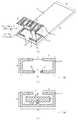
도 2에 도시된 바와 같이, 본 발명에 따른 다중대역 내장형 안테나는 상부 패치(21), 스터브(22), 중간부(23), 연결부(24), 하부 패치(25), 급전부(26), 단락부(27), 및 접지부(28)를 포함한다.As shown in FIG. 2, the multiband internal antenna according to the present invention includes an
상기 상부 패치(21)는 안테나의 상단에 위치하여 하부 패치(25)로부터 전달받은 신호를 외부로 최종적으로 방사하는 역할을 한다. 여기서, 상기 상부 패치(21)는 완전 폐루프가 아닌 한쪽이 개방된 루프 형상으로 형성되며, 본 발명에서는 그 부분을 제 1 개방부로 지칭하기로 한다.The
여기서, 상기 상부 패치(21) 중 제 1 개방부의 반대쪽에는 스터브(22)가 연결되어 있다.Here, the
그리고, 상기 스터브(22)는 본 발명의 안테나의 고주파수 대역의 대역폭을 확장시키는 역할을 한다. 즉, 상기 스터브(22)는 상기 상부 패치(21) 안쪽에 형성되어, 루프의 고차 모드에 근접한 공진을 만들어 다중 대역의 고주파수 대역에서 대역폭을 확장시키는 역할을 한다. 이 때, 상기 스터브(22)는 소정의 폭과 길이를 가지는 두 개의 직사각형의 형태로 형성된다.The
여기서, 본 발명에 대한 이해를 돕기 위하여 스터브에 대한 일반적인 내용을 살펴보면 다음과 같다.Here, look at the general content of the stub to help the understanding of the present invention.
일반적으로 스터브(Stub)란, 마이크로스트립(Microstrip)이나 스트립 라인(Strip line)으로 이루어진 회로에서 임피던스 매칭을 하기 위한 용도로 사용되는 것으로서, 신호 전송 목적이 아닌 주파수 튜닝 또는 광대역 특성을 위하여 신호 전송을 위한 선로에 부가적으로 연결되는 선로를 지칭하는 말이다. 이러한 스터브는 신호 전송을 위한 선로에 수직 방향으로 연결되는 병렬(Shunt) 스터브와 선로에 수평 방향으로 연결되는 직렬(Series) 스터브로 구분된다.Generally, a stub is used for impedance matching in a circuit composed of microstrip or strip line, and is used for signal transmission for frequency tuning or broadband characteristics, not for signal transmission purposes. It refers to a line that is additionally connected to the track for the purpose. These stubs are divided into parallel stubs connected in a vertical direction to a line for signal transmission and series stubs connected in a horizontal direction to a line.
그리고, 상기 병렬(Shunt) 스터브는 오픈(Open) 스터브와 쇼트(Short) 스터브로 나뉜다. 여기서, 오픈 스터브는 그 끝단에 아무것도 연결되지 않고 오픈된 형태로 존재하는 스터브를, 쇼트 스터브는 그 끝단에 비아(via)를 뚫어 그라운드와 접지시킨 스터브를 말한다.The parallel stub is divided into an open stub and a short stub. Here, the open stub refers to a stub that is present in an open form without connecting anything to its end, and the short stub refers to a stub that has a ground and grounded through a via at its end.
또한, 상기 오픈 스터브는 길이 L이 λ/4보다 작을 경우에는 캐패시터의 역 할을 하고, L이 λ/4보다 크고 λ/2보다 작을 경우에는 인덕턴스의 역할을 하며, 상기 쇼트 스터브는 그 반대로 동작한다.In addition, the open stub serves as a capacitor when the length L is smaller than λ / 4, and acts as an inductance when L is larger than λ / 4 and smaller than λ / 2, and the short stub operates vice versa. do.
이에 따라, 본 발명에 사용된 스터브(22)는 상부 패치(21)와 병렬로 연결된 병렬 스터브이며, 그 길이가 λ/4보다 작은 오픈 스터브이다.Accordingly, the
한편, 상기 중간부(23)는 상기 상부 패치(21)와 하부 패치(25) 사이에 소정 두께를 가지도록 공기 또는 임의의 유전체로 형성된다. 이 때, 상기 중간부(23)의 크기(가로와 세로의 길이)는 상기 상부패치(21) 또는 하부 패치(25)와 동일하다.On the other hand, the
그리고, 상기 연결부(24)는 상기 상부 패치(21)와 하부 패치(25)를 연결하여 하부 패치(25)로부터의 신호를 상부 패치(21)로 전달해주는 역할을 한다. 이 때, 상기 연결부(24)는 상기 중간부(23)가 공기가 아닌 유전체로 이루어진 경우에는 그 유전체를 통과하여 상부 패치(21)와 하부 패치(25)를 연결하도록 형성된다. 따라서, 상기 연결부(24)의 높이는 상기 중간부(23)의 두께와 동일해야 한다.In addition, the
또한, 도 2에는 상기 연결부(24)가 하부 패치(25)의 제 2 개방부의 양쪽에 바로 연결되도록 구비되어 있는데, 본 발명은 그에 한정되지 않으며, 안테나의 특성을 만족시킬 수 있는 위치라면 어느 곳에 구비하여도 무방함을 밝혀둔다.In addition, FIG. 2 is provided so that the connecting
그리고, 상기 하부 패치(25)는 상기 중간부(23)의 하단부에 위치하며, 상기 상부 패치(21)와 함께 하나의 안테나로서 동작한다. 여기서, 상기 상부 패치(21)와 상기 하부 패치(25)의 길이를 합한 패치의 총 길이는 상기 안테나의 사용 대역 중 저주파수 대역의 반파장 길이에 해당한다.In addition, the
또한, 상기 하부 패치(25)는 완전 폐루프가 아닌 대칭되는 양쪽이 개방된 즉 , 제 2 개방부와 제 3 개방부를 가지는 형태로 형성된다. 이 때, 제 2 개방부의 양 쪽 옆에는 연결부(24)가 위치하고 제 3 개방부의 양쪽 옆에는 급전부(26)와 단락부(27)가 위치한다.In addition, the
한편, 상기 급전부(26)는 상기 하부 패치(25)를 급전시키는 역할을 하며, 상기 단락부(27)는 접지부(28)와 상기 하부 패치(25)를 단락시키는 역할을 한다. 이 때, 상기 급전부(26)와 상기 단락부(27)가 함께 존재하도록 구현함으로써, 상기 하부 패치(25) 자체가 급전 선로가 아닌 안테나의 한 부분으로 동작되도록 한다.Meanwhile, the
도 3은 본 발명에 따른 스터브를 포함한 대칭 구조의 다중대역 내장형 안테나를 상세 설명하기 위한 도면으로서, 도 3을 참조하여 본 발명에 따른 스터브를 포함한 대칭 구조의 다중대역 내장형 안테나의 각 부분의 상세 사양을 살펴보면 다음과 같다.Figure 3 is a view for explaining a multi-band internal antenna of a symmetric structure including a stub according to the present invention, with reference to Figure 3 detailed specification of each part of the multi-band internal antenna of a symmetric structure including a stub according to the present invention Looking at it as follows.
여기서, 본 발명은 도 3에 도시된 안테나의 사양에 한정되는 것은 아니며, 단지 본 발명의 이해를 돕기 위하여 예를 들어 설계한 안테나의 사양을 기재한 것임을 밝혀둔다. 따라서, 안테나의 동작 주파수 및 설계 방식에 따라 각 재질, 구조 , 사이즈, 및 위치는 얼마든지 변경 가능하다.Here, the present invention is not limited to the specification of the antenna shown in FIG. 3, but it is to be noted that the specification of the antenna designed by way of example only for the purpose of understanding the present invention is described. Accordingly, the materials, structures, sizes, and positions of the antennas may be changed depending on the operating frequency and the design scheme of the antenna.
우선 상부 패치(21), 중간부(23), 및 하부 패치(25)는 가로 길이가 36mm, 세로 길이가 25mm로 모두 동일하다.First, the
여기서, 상기 상부 패치(21)와 하부 패치(25)의 폭은 2.5mm이며, 상기 상부 패치(21) 중 제 1 개방부의 간격은 10mm이고, 상기 제 1 개방부의 양쪽에서 대칭을 이루는 왼쪽과 오른쪽 패치의 길이는 각각 13mm이다.Here, the width of the
그리고, 상기 하부 패치(25)는 그 폭이 상부 패치(21)와 동일한 2.5mm이며, 급전부(26)와 단락부(27) 사이의 제 3 개방부의 간격이 6mm, 두 개의 연결부(24) 사이의 제 2 개방부의 간격이 10mm이다.The
상기 상부 패치(21)에 연결되는 스터브(22)는 가로 길이가 24mm, 세로 길이가 5mm인 직사각형과 가로와 세로가 2.5mm인 정사각형을 연결해놓은 형태로 형성된다.The
그리고, 상기 상부 패치(21), 상기 하부 패치(25), 및 상기 스터브(22)는 모두 완전 전도체(PEC : Perfect Electric Conductor)의 일종인 구리를 사용하였다.The
한편, 중간부(23)는 유전율이 4.7, 두께가 2.4mm인 에폭시(FR4)를 사용하였으며, 접지부(28)와 상기 하부 패치(25) 사이의 공간은 3.6mm만큼 이격되어 있다.Meanwhile, the
그리고, 접지부(28)는 가로 80mm, 세로 36mm인 직사각형 기판으로 이루어진다.The
도 3에 나타낸 안테나의 사양은 전술한 바와 같이, 본 발명에 대한 이해를 돕기 위해 예를 들어 설계된 안테나의 사양이므로 그에 한정되는 것은 아니며, 후술할 도 4 내지 도 8의 안테나 특성은 모두 도 3에 나타낸 사양으로 설계된 안테나를 이용하여 측정한 안테나 특성임을 밝혀둔다.As described above, the specification of the antenna shown in FIG. 3 is, for example, a specification of an antenna designed to help an understanding of the present invention, and thus is not limited thereto. The antenna characteristics of FIGS. Note that this is an antenna characteristic measured using an antenna designed with the specifications shown.
도 4는 본 발명에 따른 스터브를 포함한 대칭 구조의 다중대역 내장형 안테나가 저주파수 대역에서 동작하는 경우의 표면 전류 벡터를 나타낸 도면으로서, 도 4a는 안테나의 상부 패치(21)에서의 전류 흐름을, 도 4b는 안테나의 하부 패치(25)에서의 전류 흐름을 나타낸 것이다.4 is a diagram showing a surface current vector when a symmetrical multiband internal antenna including a stub according to the present invention operates in a low frequency band, and FIG. 4A shows a current flow in the
여기서, 화살표의 크기는 전류의 크기를 나타낸 것이며, 도 4에 도시된 바와 같이, 본 발명에 따른 스터브를 포함한 대칭 구조의 다중대역 내장형 안테나가 저주파수에서 동작하는 경우에는 표면 전류 밀도가 상부 패치(21)와 하부 패치(25) 모두에서 좌우 대칭적으로 분포됨을 알 수 있다.Here, the size of the arrow indicates the magnitude of the current, as shown in Figure 4, when the multi-band internal antenna of the symmetric structure including the stub according to the present invention operates at a low frequency, the surface current density is the upper patch (21) It can be seen that the symmetrical distribution in both) and the
도 5는 본 발명에 따른 스터브를 포함한 대칭 구조의 다중대역 내장형 안테나가 고주파수 대역에서 동작하는 경우의 표면 전류 벡터를 나타낸 도면으로서, 도 5a는 안테나의 상부 패치(21)에서의 전류 흐름을, 도 5b는 하부 패치(25)에서의 전류 흐름을 나타낸 것이다.FIG. 5 is a diagram showing a surface current vector when a multiband internal antenna having a symmetric structure including a stub according to the present invention operates in a high frequency band, and FIG. 5A shows a current flow in the
여기서, 화살표의 크기는 도 4에서와 같이 전류의 크기를 나타낸 것이며, 도 5에 도시된 바와 같이, 본 발명에 따른 안테나가 고주파수에서 동작하는 경우에도 도 4의 안테나가 저주파수에서 동작하는 경우와 같이 표면 전류 밀도가 상부 패치(21)와 하부 패치(25) 모두에서 좌우 대칭적으로 분포됨을 알 수 있다.Here, the size of the arrow shows the magnitude of the current as shown in Figure 4, as shown in Figure 5, even when the antenna of the present invention operates at a high frequency, as in the case of the antenna of Figure 4 operates at a low frequency It can be seen that the surface current density is symmetrically distributed in both the
이러한 안테나의 표면 전류 밀도는 방사 패턴에 직접적으로 영향을 미치며, 좌우 대칭적으로 고른 전류 분포는 전자파 인체 흡수율(SAR)을 낮출 수 있으므로, 이로 인하여 본 발명에 따른 안테나는 고주파수 대역에서 얻기가 어려운 전방향성 방사 패턴을 얻을 수 있고, 그와 더불어 전자파 인체 흡수율(SAR)을 저감시킬 수 있는 것이다.The surface current density of such an antenna directly affects the radiation pattern, and the symmetrically even current distribution can lower the electromagnetic wave absorption rate (SAR). Therefore, the antenna according to the present invention is difficult to obtain in the high frequency band. The directional radiation pattern can be obtained, and at the same time, the electromagnetic wave absorption rate (SAR) can be reduced.
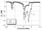
도 6은 본 발명에 따른 스터브를 포함한 대칭 구조의 다중대역 내장형 안테나에 스터브가 포함된 경우와 포함되지 않은 경우의 반사계수 특성을 비교 설명하기 위한 도면이다.FIG. 6 is a view for comparing and explaining reflection coefficient characteristics when a stub is included in a multiband internal antenna having a stub according to the present invention and when it is not included.
여기서, (a) 그래프는 스터브가 포함되지 않은 경우의 안테나 반사계수를, (b) 그래프는 스터브가 포함된 경우의 안테나의 반사계수를 나타낸 것이다.Here, (a) the graph shows the antenna reflection coefficient when the stub is not included, (b) the graph shows the reflection coefficient of the antenna when the stub is included.
(a) 그래프를 먼저 살펴보면, 스터브가 포함되지 않은 경우에는 공진 주파수 -6dB 이하(정재파비 3 이하)의 반사계수를 기준으로 그 대역폭이 저주파수 대역(860MHz 중심)에서는 50MHz, 고주파수 대역(2550MHz 중심)에서는 210MHz로 나타난다.(a) Looking at the graph first, if the stub is not included, the bandwidth is 50MHz in the low frequency band (center 860MHz) and high frequency band (center 2550MHz) based on the reflection coefficient of the resonance frequency of -6dB or less (standing wave ratio 3 or less). At 210MHz.
그리고, (b) 그래프를 살펴보면, 스터브가 포함된 경우에는 동일한 조건(공진 주파수 -6dB 이하(정재파비 3 이하)의 반사계수를 기준)에서 그 대역폭이 저주파수 대역(800MHz 중심)에서 40MHz, 고주파수 대역(2800MHz)에서 430MHz로 나타난다.In the graph (b), when the stub is included, the bandwidth is 40 MHz in the low frequency band (centered at 800 MHz) under the same conditions (based on the reflection coefficient under the resonance frequency of -6 dB or less (the standing wave ratio 3 or less)). It appears from (2800MHz) to 430MHz.
이렇게, 본 발명에 따른 안테나는 스터브를 포함함으로써, 고주파수 대역의 대역폭이 상당히 큰 폭(210MHz에서 430MHz)으로 확장됨을 알 수 있다.Thus, it can be seen that the antenna according to the present invention includes a stub so that the bandwidth of the high frequency band is extended to a considerably large width (210 MHz to 430 MHz).
도 7은 본 발명에 따른 스터브를 포함한 대칭 구조의 다중대역 내장형 안테나가 저주파수 대역에서 동작하는 경우의 방사 패턴을 설명하기 위한 도면이며, 도 8은 본 발명에 따른 스터브를 포함한 대칭 구조의 다중대역 내장형 안테나가 고주파수 대역에서 동작하는 경우의 방사 패턴을 설명하기 위한 도면이다.7 is a view illustrating a radiation pattern when the symmetrical multiband internal antenna including a stub according to the present invention operates in a low frequency band, and FIG. 8 is a symmetrical multiband internal antenna including a stub according to the present invention. A diagram for describing a radiation pattern when the antenna operates in a high frequency band.
도 7 및 도 8에 도시된 바와 같이, 본 발명에 따른 스터브를 포함한 대칭 구조의 다중대역 내장형 안테나는 저주파수 대역과 고주파수 대역 모두에서 전방향성의 방사 패턴을 나타내고 있다. 이는, 본 발명에 따른 안테나의 상부 패치와 하부 패치 모두가 대칭 구조로 형성되어 있으므로 나타나는 특성으로서 안테나에 있어서 상단한 장점으로 작용한다.As shown in Figures 7 and 8, the multi-band internal antenna of the symmetric structure including the stub according to the present invention shows the omnidirectional radiation pattern in both the low frequency band and high frequency band. This is a characteristic that appears because both the upper patch and the lower patch of the antenna according to the present invention is formed in a symmetrical structure serves as a top advantage in the antenna.
이상에서 설명한 본 발명은, 본 발명이 속하는 기술분야에서 통상의 지식을 가진 자에게 있어 본 발명의 기술적 사상을 벗어나지 않는 범위 내에서 여러 가지 치환, 변형 및 변경이 가능하므로 전술한 실시예 및 첨부된 도면에 의해 한정되는 것이 아니다.The present invention described above is capable of various substitutions, modifications, and changes without departing from the technical spirit of the present invention for those skilled in the art to which the present invention pertains. It is not limited by the drawings.
상기와 같은 본 발명은, 루프형 안테나를 적층 구조로 구현함으로써, 안테나의 사이즈를 줄일 수 있는 효과가 있다.The present invention as described above, by implementing a loop antenna in a stacked structure, there is an effect that can reduce the size of the antenna.
또한, 본 발명은 상부 패치에 연결하는 스터브를 이용하여 안테나 동작 주파수 중 고주파수 대역의 대역폭을 큰 폭으로 확장시킬 수 있는 효과가 있다.In addition, the present invention has an effect that can greatly extend the bandwidth of the high frequency band of the operating frequency of the antenna by using a stub connected to the upper patch.
또한, 본 발명은 안테나 패치를 좌우 대칭적인 구조로 형성함으로써, 전류 밀도 분포를 고르게 하여 전자파 인체 흡수율(SAR)을 저감시키고, 안테나의 동작 주파수 전체(저주파수 대역 및 고주파수 대역)에 대해 전방향성의 방사 패턴을 얻을 수 있는 효과가 있다.In addition, the present invention by forming the antenna patch in a symmetrical structure, evenly distributed current density to reduce the electromagnetic absorption rate (SAR), and omni-directional radiation over the entire operating frequency (low frequency band and high frequency band) of the antenna The effect is to get a pattern.
Claims (9)
Translated fromKoreanPriority Applications (3)
| Application Number | Priority Date | Filing Date | Title |
|---|---|---|---|
| KR1020040089854AKR100597581B1 (en) | 2004-11-05 | 2004-11-05 | Symmetrical Multiband Internal Antenna with Stubs |
| US11/718,087US7782257B2 (en) | 2004-11-05 | 2005-07-04 | Multi-band internal antenna of symmetry structure having stub |
| PCT/KR2005/002116WO2006049382A1 (en) | 2004-11-05 | 2005-07-04 | Multi-band internal antenna of symmetry structure having stub |
Applications Claiming Priority (1)
| Application Number | Priority Date | Filing Date | Title |
|---|---|---|---|
| KR1020040089854AKR100597581B1 (en) | 2004-11-05 | 2004-11-05 | Symmetrical Multiband Internal Antenna with Stubs |
Publications (2)
| Publication Number | Publication Date |
|---|---|
| KR20060040312A KR20060040312A (en) | 2006-05-10 |
| KR100597581B1true KR100597581B1 (en) | 2006-07-06 |
Family
ID=36319363
Family Applications (1)
| Application Number | Title | Priority Date | Filing Date |
|---|---|---|---|
| KR1020040089854AExpired - Fee RelatedKR100597581B1 (en) | 2004-11-05 | 2004-11-05 | Symmetrical Multiband Internal Antenna with Stubs |
Country Status (3)
| Country | Link |
|---|---|
| US (1) | US7782257B2 (en) |
| KR (1) | KR100597581B1 (en) |
| WO (1) | WO2006049382A1 (en) |
Cited By (2)
| Publication number | Priority date | Publication date | Assignee | Title |
|---|---|---|---|---|
| KR101413986B1 (en)* | 2012-12-26 | 2014-07-04 | 전자부품연구원 | Patch Antenna having a Patch Fed with Mulitiple Signal |
| CN109037915A (en)* | 2018-06-14 | 2018-12-18 | 杭州电子科技大学 | Miniature omnidirectional microstrip antenna |
Families Citing this family (34)
| Publication number | Priority date | Publication date | Assignee | Title |
|---|---|---|---|---|
| US7589675B2 (en)* | 2006-05-19 | 2009-09-15 | Industrial Technology Research Institute | Broadband antenna |
| KR100797172B1 (en)* | 2006-08-08 | 2008-01-23 | 삼성전자주식회사 | Loop antenna with integral matching circuit |
| KR100824382B1 (en)* | 2006-09-12 | 2008-04-22 | 삼성전자주식회사 | Folded dipole loop antenna with integral matching circuit |
| GB0700218D0 (en)* | 2007-01-06 | 2007-02-14 | Isis Innovation | Planar tripolar antenna |
| KR100860742B1 (en)* | 2007-01-25 | 2008-09-29 | 한양대학교 산학협력단 | RFID tag antenna |
| KR101404744B1 (en)* | 2007-10-12 | 2014-06-10 | 엘지전자 주식회사 | Loop antenna and portable terminal having the same |
| WO2010036279A1 (en)* | 2007-11-28 | 2010-04-01 | Qualcomm Incorporated | Wireless power range increase using parasitic antennas |
| KR100954879B1 (en)* | 2007-12-04 | 2010-04-28 | 삼성전기주식회사 | Antenna-embedded printed circuit board |
| CN101453049B (en)* | 2007-12-04 | 2013-04-03 | 广达电脑股份有限公司 | Ultra-wideband antenna |
| KR100956746B1 (en)* | 2007-12-18 | 2010-05-12 | 주식회사 에이스테크놀로지 | Reduced Human Effect Multilayer Dielectric Symmetric Antenna |
| US8315578B2 (en)* | 2008-07-15 | 2012-11-20 | Research In Motion Limited | Mobile wireless communications device with separate in-phase and quadrature power amplification |
| US20100060541A1 (en)* | 2008-09-08 | 2010-03-11 | Smartant Telecom Co., Ltd. | Antenna |
| GB2472779B (en)* | 2009-08-17 | 2013-08-14 | Microsoft Corp | Antennas with multiple feed circuits |
| GB2484540B (en) | 2010-10-15 | 2014-01-29 | Microsoft Corp | A loop antenna for mobile handset and other applications |
| CN102487156B (en)* | 2010-12-02 | 2015-09-02 | 深圳富泰宏精密工业有限公司 | Multifrequency antenna and apply the radio communication device of this multifrequency antenna |
| KR101874323B1 (en)* | 2011-04-13 | 2018-07-05 | 타이코 파이어 앤 시큐리티 게엠베하 | Small broadband loop antenna for near field applications |
| US9531068B2 (en)* | 2011-04-21 | 2016-12-27 | General Wireless IP Holdings, LLC | Efficient loop antenna system and method |
| CN103311650B (en)* | 2012-03-16 | 2016-08-24 | 华为终端有限公司 | Antenna and wireless terminal device |
| KR101926549B1 (en)* | 2012-07-23 | 2019-03-12 | 엘지이노텍 주식회사 | Antenna apparatus |
| US9425496B2 (en) | 2012-09-27 | 2016-08-23 | Apple Inc. | Distributed loop speaker enclosure antenna |
| US8922443B2 (en) | 2012-09-27 | 2014-12-30 | Apple Inc. | Distributed loop antenna with multiple subloops |
| JP6033693B2 (en)* | 2013-01-22 | 2016-11-30 | 京セラ株式会社 | Electronics |
| KR20150098343A (en) | 2014-02-20 | 2015-08-28 | 현대자동차주식회사 | Dual band PCB antenna for vehicle |
| TWI590527B (en)* | 2015-04-17 | 2017-07-01 | 宏碁股份有限公司 | Antenna structure |
| CN106299614A (en)* | 2015-05-29 | 2017-01-04 | 宏碁股份有限公司 | Antenna structure |
| CN205376750U (en)* | 2016-01-12 | 2016-07-06 | 中磊电子(苏州)有限公司 | Dual -band antenna |
| US10333222B2 (en) | 2016-04-11 | 2019-06-25 | Electronics And Telecommunications Research Institute | Method of improving bandwidth of antenna using transmission line stub |
| CN107645038B (en)* | 2016-07-20 | 2019-11-29 | 华为技术有限公司 | A kind of antenna and mobile terminal |
| US10320078B2 (en)* | 2016-11-18 | 2019-06-11 | QuantalRF AG | Small form factor CPL antenna with balanced fed dipole electric field radiator |
| CN107994345B (en)* | 2017-10-10 | 2020-11-13 | 捷开通讯(深圳)有限公司 | Antenna of mobile terminal and mobile terminal |
| CN114095050B (en)* | 2020-07-29 | 2022-12-27 | 华为技术有限公司 | Wireless terminal |
| TWI748700B (en)* | 2020-10-22 | 2021-12-01 | 廣達電腦股份有限公司 | Antenna structure |
| WO2022111064A1 (en)* | 2020-11-30 | 2022-06-02 | Oppo广东移动通信有限公司 | Electronic device |
| WO2023155156A1 (en)* | 2022-02-18 | 2023-08-24 | 广州视源电子科技股份有限公司 | Antenna assembly and interactive panel |
Citations (1)
| Publication number | Priority date | Publication date | Assignee | Title |
|---|---|---|---|---|
| US20040178958A1 (en) | 2002-11-08 | 2004-09-16 | Kadambi Govind R. | Antenna with shorted active and passive planar loops and method of making the same |
Family Cites Families (10)
| Publication number | Priority date | Publication date | Assignee | Title |
|---|---|---|---|---|
| US5864123A (en) | 1995-06-02 | 1999-01-26 | Keefer; Richard M. | Smart microwave packaging structures |
| WO2001080354A1 (en)* | 2000-04-14 | 2001-10-25 | Rangestar Wireless, Inc. | Compact dual frequency antenna with multiple polarization |
| DE10049845A1 (en)* | 2000-10-09 | 2002-04-11 | Philips Corp Intellectual Pty | Multiband microwave aerial with substrate with one or more conductive track structures |
| US6542123B1 (en)* | 2001-10-24 | 2003-04-01 | Auden Techno Corp. | Hidden wideband antenna |
| TW506163B (en)* | 2001-12-19 | 2002-10-11 | Ind Tech Res Inst | Planar inverted-F antenna |
| KR100842553B1 (en) | 2002-01-17 | 2008-07-01 | 삼성전자주식회사 | Different Ranging Code Set Assignment Method for with the Adjacent Cells in OFDM System |
| KR100483043B1 (en)* | 2002-04-11 | 2005-04-18 | 삼성전기주식회사 | Multi band built-in antenna |
| KR100566201B1 (en) | 2002-04-22 | 2006-03-29 | 삼성전자주식회사 | Ranging Method in Mobile Communication System using Orthogonal Frequency Division Multiple Access |
| US6911940B2 (en)* | 2002-11-18 | 2005-06-28 | Ethertronics, Inc. | Multi-band reconfigurable capacitively loaded magnetic dipole |
| KR100535255B1 (en) | 2002-12-17 | 2005-12-08 | 한국전자통신연구원 | Small planar antenna with ultra wide bandwidth and manufacturing method thereof |
- 2004
- 2004-11-05KRKR1020040089854Apatent/KR100597581B1/ennot_activeExpired - Fee Related
- 2005
- 2005-07-04USUS11/718,087patent/US7782257B2/ennot_activeExpired - Fee Related
- 2005-07-04WOPCT/KR2005/002116patent/WO2006049382A1/enactiveApplication Filing
Patent Citations (1)
| Publication number | Priority date | Publication date | Assignee | Title |
|---|---|---|---|---|
| US20040178958A1 (en) | 2002-11-08 | 2004-09-16 | Kadambi Govind R. | Antenna with shorted active and passive planar loops and method of making the same |
Cited By (3)
| Publication number | Priority date | Publication date | Assignee | Title |
|---|---|---|---|---|
| KR101413986B1 (en)* | 2012-12-26 | 2014-07-04 | 전자부품연구원 | Patch Antenna having a Patch Fed with Mulitiple Signal |
| CN109037915A (en)* | 2018-06-14 | 2018-12-18 | 杭州电子科技大学 | Miniature omnidirectional microstrip antenna |
| CN109037915B (en)* | 2018-06-14 | 2020-07-07 | 杭州电子科技大学 | Miniature Omnidirectional Microstrip Antenna |
Also Published As
| Publication number | Publication date |
|---|---|
| KR20060040312A (en) | 2006-05-10 |
| US7782257B2 (en) | 2010-08-24 |
| US20090135077A1 (en) | 2009-05-28 |
| WO2006049382A1 (en) | 2006-05-11 |
Similar Documents
| Publication | Publication Date | Title |
|---|---|---|
| KR100597581B1 (en) | Symmetrical Multiband Internal Antenna with Stubs | |
| US10734723B2 (en) | Couple multiband antennas | |
| US7116276B2 (en) | Ultra wideband internal antenna | |
| EP3245691B1 (en) | Low common mode resonance multiband radiating array | |
| KR100771775B1 (en) | Vertical Array Internal Antenna | |
| JP3828106B2 (en) | Built-in antenna of mobile communication terminal | |
| US6380903B1 (en) | Antenna systems including internal planar inverted-F antennas coupled with retractable antennas and wireless communicators incorporating same | |
| TWI431849B (en) | Mobile communication device | |
| KR101163419B1 (en) | Hybrid Patch Antenna | |
| KR100616545B1 (en) | Multi-band laminated chip antenna using double coupling feeding | |
| JP2007089234A (en) | antenna | |
| KR100638661B1 (en) | Ultra Wideband Internal Antenna | |
| CN108493588A (en) | Indoor base station and its PIFA antennas | |
| KR20090096914A (en) | Planar folded monopole antenna | |
| KR20080095597A (en) | Broadband internal antenna | |
| CN209948040U (en) | Dual-frequency dual-horizontal polarization omnidirectional antenna | |
| CN207409650U (en) | A kind of microstrip antenna | |
| Chen et al. | Compact PIFA using capacitive coupled-fed for LTE/GSM/UMTS WWAN operation in the mobile application | |
| Chang et al. | Bandwidth enhancement of internal WWAN antenna using an inductively coupled plate in the small‐size mobile phone | |
| Hsu et al. | Novel planar wideband omni-directional quasi log-periodic antenna | |
| Jiang et al. | A broadband horizontally polarized omnidirectional antenna array consisting of four corrugated TSA elements | |
| KR100883990B1 (en) | Broadband internal antenna | |
| US20190190153A1 (en) | Ultra wide band antenna | |
| KR20100065445A (en) | Multi-Band Internal Loop Antenna with Up-Down Symmetry | |
| US20070268184A1 (en) | Metal inverted F antenna |
Legal Events
| Date | Code | Title | Description |
|---|---|---|---|
| A201 | Request for examination | ||
| PA0109 | Patent application | St.27 status event code:A-0-1-A10-A12-nap-PA0109 | |
| PA0201 | Request for examination | St.27 status event code:A-1-2-D10-D11-exm-PA0201 | |
| D13-X000 | Search requested | St.27 status event code:A-1-2-D10-D13-srh-X000 | |
| PG1501 | Laying open of application | St.27 status event code:A-1-1-Q10-Q12-nap-PG1501 | |
| D14-X000 | Search report completed | St.27 status event code:A-1-2-D10-D14-srh-X000 | |
| E701 | Decision to grant or registration of patent right | ||
| PE0701 | Decision of registration | St.27 status event code:A-1-2-D10-D22-exm-PE0701 | |
| GRNT | Written decision to grant | ||
| PR0701 | Registration of establishment | St.27 status event code:A-2-4-F10-F11-exm-PR0701 | |
| PR1002 | Payment of registration fee | St.27 status event code:A-2-2-U10-U11-oth-PR1002 Fee payment year number:1 | |
| PG1601 | Publication of registration | St.27 status event code:A-4-4-Q10-Q13-nap-PG1601 | |
| PR1001 | Payment of annual fee | St.27 status event code:A-4-4-U10-U11-oth-PR1001 Fee payment year number:4 | |
| PN2301 | Change of applicant | St.27 status event code:A-5-5-R10-R13-asn-PN2301 St.27 status event code:A-5-5-R10-R11-asn-PN2301 | |
| PR1001 | Payment of annual fee | St.27 status event code:A-4-4-U10-U11-oth-PR1001 Fee payment year number:5 | |
| PR1001 | Payment of annual fee | St.27 status event code:A-4-4-U10-U11-oth-PR1001 Fee payment year number:6 | |
| FPAY | Annual fee payment | Payment date:20120611 Year of fee payment:7 | |
| PR1001 | Payment of annual fee | St.27 status event code:A-4-4-U10-U11-oth-PR1001 Fee payment year number:7 | |
| LAPS | Lapse due to unpaid annual fee | ||
| PC1903 | Unpaid annual fee | St.27 status event code:A-4-4-U10-U13-oth-PC1903 Not in force date:20130630 Payment event data comment text:Termination Category : DEFAULT_OF_REGISTRATION_FEE | |
| PC1903 | Unpaid annual fee | St.27 status event code:N-4-6-H10-H13-oth-PC1903 Ip right cessation event data comment text:Termination Category : DEFAULT_OF_REGISTRATION_FEE Not in force date:20130630 | |
| PN2301 | Change of applicant | St.27 status event code:A-5-5-R10-R13-asn-PN2301 St.27 status event code:A-5-5-R10-R11-asn-PN2301 |