KR100595238B1 - Shelf Structure of Combined Drying Equipment - Google Patents
Shelf Structure of Combined Drying EquipmentDownload PDFInfo
- Publication number
- KR100595238B1 KR100595238B1KR1020040099136AKR20040099136AKR100595238B1KR 100595238 B1KR100595238 B1KR 100595238B1KR 1020040099136 AKR1020040099136 AKR 1020040099136AKR 20040099136 AKR20040099136 AKR 20040099136AKR 100595238 B1KR100595238 B1KR 100595238B1
- Authority
- KR
- South Korea
- Prior art keywords
- hot air
- dryer
- laundry
- supply pipe
- cabinet
- Prior art date
- Legal status (The legal status is an assumption and is not a legal conclusion. Google has not performed a legal analysis and makes no representation as to the accuracy of the status listed.)
- Expired - Fee Related
Links
Images


Classifications
- D—TEXTILES; PAPER
- D06—TREATMENT OF TEXTILES OR THE LIKE; LAUNDERING; FLEXIBLE MATERIALS NOT OTHERWISE PROVIDED FOR
- D06F—LAUNDERING, DRYING, IRONING, PRESSING OR FOLDING TEXTILE ARTICLES
- D06F58/00—Domestic laundry dryers
- D06F58/10—Drying cabinets or drying chambers having heating or ventilating means
- D—TEXTILES; PAPER
- D06—TREATMENT OF TEXTILES OR THE LIKE; LAUNDERING; FLEXIBLE MATERIALS NOT OTHERWISE PROVIDED FOR
- D06F—LAUNDERING, DRYING, IRONING, PRESSING OR FOLDING TEXTILE ARTICLES
- D06F29/00—Combinations of a washing machine with other separate apparatus in a common frame or the like, e.g. with rinsing apparatus
- D06F29/005—Combinations of a washing machine with other separate apparatus in a common frame or the like, e.g. with rinsing apparatus the other separate apparatus being a drying appliance
- D—TEXTILES; PAPER
- D06—TREATMENT OF TEXTILES OR THE LIKE; LAUNDERING; FLEXIBLE MATERIALS NOT OTHERWISE PROVIDED FOR
- D06F—LAUNDERING, DRYING, IRONING, PRESSING OR FOLDING TEXTILE ARTICLES
- D06F57/00—Supporting means, other than simple clothes-lines, for linen or garments to be dried or aired
- D06F57/12—Supporting means, other than simple clothes-lines, for linen or garments to be dried or aired specially adapted for attachment to walls, ceilings, stoves, or other structures or objects
- D—TEXTILES; PAPER
- D06—TREATMENT OF TEXTILES OR THE LIKE; LAUNDERING; FLEXIBLE MATERIALS NOT OTHERWISE PROVIDED FOR
- D06F—LAUNDERING, DRYING, IRONING, PRESSING OR FOLDING TEXTILE ARTICLES
- D06F58/00—Domestic laundry dryers
- D06F58/16—Domestic laundry dryers having heatable surfaces for contacting the laundry
- D—TEXTILES; PAPER
- D06—TREATMENT OF TEXTILES OR THE LIKE; LAUNDERING; FLEXIBLE MATERIALS NOT OTHERWISE PROVIDED FOR
- D06F—LAUNDERING, DRYING, IRONING, PRESSING OR FOLDING TEXTILE ARTICLES
- D06F2101/00—User input for the control of domestic laundry washing machines, washer-dryers or laundry dryers
- D06F2101/16—Target humidity for the drying process, e.g. very-dry cycles
- D—TEXTILES; PAPER
- D06—TREATMENT OF TEXTILES OR THE LIKE; LAUNDERING; FLEXIBLE MATERIALS NOT OTHERWISE PROVIDED FOR
- D06F—LAUNDERING, DRYING, IRONING, PRESSING OR FOLDING TEXTILE ARTICLES
- D06F2103/00—Parameters monitored or detected for the control of domestic laundry washing machines, washer-dryers or laundry dryers
- D06F2103/52—Parameters monitored or detected for the control of domestic laundry washing machines, washer-dryers or laundry dryers related to electric heating means, e.g. temperature or voltage
- D—TEXTILES; PAPER
- D06—TREATMENT OF TEXTILES OR THE LIKE; LAUNDERING; FLEXIBLE MATERIALS NOT OTHERWISE PROVIDED FOR
- D06F—LAUNDERING, DRYING, IRONING, PRESSING OR FOLDING TEXTILE ARTICLES
- D06F2105/00—Systems or parameters controlled or affected by the control systems of washing machines, washer-dryers or laundry dryers
- D06F2105/16—Air properties
- D06F2105/20—Temperature
- D—TEXTILES; PAPER
- D06—TREATMENT OF TEXTILES OR THE LIKE; LAUNDERING; FLEXIBLE MATERIALS NOT OTHERWISE PROVIDED FOR
- D06F—LAUNDERING, DRYING, IRONING, PRESSING OR FOLDING TEXTILE ARTICLES
- D06F2105/00—Systems or parameters controlled or affected by the control systems of washing machines, washer-dryers or laundry dryers
- D06F2105/30—Blowers
Landscapes
- Engineering & Computer Science (AREA)
- Textile Engineering (AREA)
- Detail Structures Of Washing Machines And Dryers (AREA)
Abstract
Translated fromKoreanDescription
Translated fromKorean도 1 은 종래 일반적인 드럼식 건조기의 내부 구조를 설명하기 위한 구성도1 is a configuration diagram for explaining the internal structure of a conventional general drum type dryer
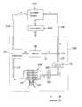
도 2 는 본 발명의 실시예에 따른 건조 장치의 외관을 개략적으로 나타낸 구성도Figure 2 is a schematic view showing the appearance of the drying apparatus according to an embodiment of the present invention
도 3 은 도 2의 I-I를 나타낸 종단면도3 is a longitudinal sectional view showing the I-I of FIG.
도 4 는 본 발명의 실시예에 따른 건조 장치를 개략적으로 나타낸 블럭도4 is a schematic block diagram of a drying apparatus according to an embodiment of the present invention.
도 5 는 본 발명의 실시예에 따른 선반의 구조를 나타낸 사시도5 is a perspective view showing the structure of a shelf according to an embodiment of the present invention
도 6 은 도 5의 II-II를 나타낸 종단면도.6 is a longitudinal sectional view showing II-II of FIG. 5;
** 도면의 주요부분에 대한 부호의 설명 **** Explanation of symbols for main parts of drawings **
100. 드럼식 건조기110. 건조드럼100.
121. 제1공급관122. 제2공급관121.
123. 제3공급관124. 걸름부123. Third Supply Pipe 124. Filtering part
125. 유로밸브130. 열풍 공급부125.
140. 공기 응축부141. 응축기140.
142. 응축팬200. 캐비닛 건조기142. Condensate Pan 200. Cabinet Dryer
210. 몸체222. 걸이바210.Body 222. Hanger Bar
230. 개폐 도어241. 열풍 유입관230. Opening and closing door 241. Hot air inlet pipe
242. 공기 유출관250. 연장부242.
241a: 열풍 배출구300: 선반241a: hot air outlet 300: shelf
310: 몸체부320: 돌출부310: body portion 320: protrusion
330: 보조열풍공급관331: 열풍토출공330: auxiliary hot air supply pipe 331: hot air discharge air
340: 열풍통과로400: 컨트롤부340: hot air passage 400: control unit
본 발명은 건조 장치에 관한 것으로서, 더욱 상세하게는 세탁물 건조를 위한 공기가 상기 건조 장치를 계속적으로 순환될 수 있도록 하되, 보다 원활한 건조가 가능하도록 하여 빌트인으로의 제공에 적합할 수 있도록 함과 더불어 실내 환경의 변화를 최대한 방지할 수 있도록 한 새로운 구조의 건조 장치에 관한 것이다.The present invention relates to a drying apparatus, and more particularly, to allow the air for laundry drying to be continuously circulated through the drying apparatus, to allow more smooth drying, and to be suitable for providing the built-in. The present invention relates to a drying apparatus of a new structure that can prevent the change of the indoor environment to the maximum.
일반적으로 건조 장치는 의류 등의 세탁물을 건조하는 기기로써, 세탁이 완료된 세탁물을 제공받아 고온의 열기를 지속적으로 공급함으로써 상기 세탁물의 건조를 수행한다.In general, a drying apparatus is a device for drying laundry such as clothes, and receives laundry to which washing is completed to continuously supply high temperature heat to perform drying of the laundry.
도시한 도 1은 전술한 종래의 건조 장치 중 일반적인 드럼식 건조기가 도시되고 있다.FIG. 1 shows a general drum type dryer of the above-described conventional drying apparatus.
즉, 종래 드럼식 건조기는 크게 본체(10)와, 건조드럼(20)과, 도어(40)와, 모터(50)와, 건조히터(60)와, 송풍팬(70)을 포함하여 구성된다.That is, the conventional drum dryer is largely comprised of the
상기 본체(10)는 드럼식 건조기의 외관을 형성하고, 상기 건조드럼(20)은 상 기 본체(10) 내에 회전 가능하게 설치된다.The
또한, 상기 본체(10)의 전면에는 투입구(11)가 형성되고, 상기 도어(40)는 상기 투입구(11)를 개폐하도록 장착된다.In addition, an
그리고, 상기 모터(50)는 상기 본체(10)의 내측 저부에 고정되어 건조드럼(20) 및 상기 송풍팬(70)을 회전시키기 위한 구동력을 발생한다.The
그리고, 상기 건조히터(60)는 열풍공급유로(91)의 내측에 설치되어 상기 열풍공급유로(91)의 내부를 유동하는 공기를 가열시킨다. 이 때, 상기 열풍공급유로(91)는 건조드럼(20) 내로 공급되는 열풍의 유동을 안내한다.The
그리고, 상기 송풍팬(70)은 상기 건조드럼(10) 내부를 유동하는 건조 공기를 본체(10) 외부로 배출하도록 동작되며, 열풍배출유로(92)와 연통되게 구비된다.In addition, the blowing
따라서, 상기 송풍팬(70)이 작동되면 외부 공기는 열풍공급유로(91)의 안내를 받아 유동되고, 상기 유동 도중 건조히터(60)를 지나면서 고온화 되어 건조드럼(10) 내로 유입된다.Therefore, when the blowing
이로 인해, 상기 건조드럼(10) 내에 투입된 젖은 세탁물은 상기 고온화된 외부 공기에 의해 점차 건조된다.For this reason, the wet laundry introduced into the drying
또한, 상기 건조드럼(10) 내를 유동하면서 상기 세탁물을 건조시킨 공기는 열풍배출유로(92)의 안내를 받아 본체(10) 외부로 배출된다.In addition, the air drying the laundry while flowing in the drying
그리고, 상기한 과정의 반복 수행에 의해 세탁물의 건조가 완료되면 송풍팬(70)과 건조히터(60)의 동작이 중단됨으로써 건조 행정이 종료된다.Then, when the laundry is dried by repeating the above process, the operation of the blowing
하지만, 종래의 드럼식 건조기는 세탁물이 일괄적으로 투입된 상태로 건조 과정이 진행되기 때문에 엉켜진 부위에 대한 원활한 건조가 이루어지지 못한다는 문제점이 있었다.However, the conventional drum dryer has a problem that the drying process is not performed smoothly because the drying process proceeds in a state in which laundry is put in a batch.
뿐만 아니라, 드럼식 건조기 내에서의 장시간 보존이 불가능하다는 문제점 역시 있었다.In addition, there was a problem that long-term storage in the drum dryer is impossible.
이에 따라, 최근에는 건조 용량을 확대하고, 장시간의 보관도 가능하도록 한 새로운 건조 장치에 대한 요구가 이루어졌으며, 미국특허출원공개 US2004/0194339 A1 및 US2004/0154194 A1과 같이 드럼식 건조기에 별도의 건조 캐비닛을 더 구비된 혼합식 건조기가 제공되고 있다.Accordingly, there has recently been a demand for a new drying apparatus that can extend the drying capacity and allow for long-term storage, and separate drying cabinets for drum dryers such as US Patent Application Publication US2004 / 0194339 A1 and US2004 / 0154194 A1. There is provided a mixed dryer further provided.
상기와 같은 혼합식 건조기는 회전되는 드럼을 가지는 일반적인 드럼식 건조기의 상측에 각종 세탁물의 수납 공간을 가지면서 열풍을 공급받는 건조 캐비닛이 장착되어 이루어진 건조 기기이다.Mixing dryer as described above is a drying device is equipped with a drying cabinet supplied with hot air while having a storage space for various laundry on the upper side of the general drum type dryer having a rotating drum.
이 때, 상기 건조 캐비닛은 상기 드럼식 건조기로부터 열풍을 공급받아 그 내부에 수납되는 의류 등을 건조시키거나 장시간 보관하는데 사용된다.In this case, the drying cabinet receives hot air from the drum dryer and is used to dry clothes or store clothes for a long time.
하지만, 전술한 혼합식 건조기는 세탁물을 건조시킨 공기가 기기 외부로 배출되는 배기식 구조이기 때문에 빌트인으로의 제공이 곤란한 문제점이 야기된다.However, the above-described mixed dryer has a problem in that it is difficult to provide the built-in because the air drying the laundry is exhausted to the outside of the apparatus.
즉, 빌트인을 위한 공간은 혼합식 건조기 외부로의 원활한 공기 배출을 위해 벽면과의 충분한 간격을 유지할 수 있을 정도로 크게 형성되어야만 함으로써 상기 간격으로 인한 외관 디자인의 저하가 야기될 수 밖에 없었던 것이다.In other words, the space for the built-in should be large enough to maintain a sufficient distance from the wall for smooth air discharge to the outside of the mixing dryer, thereby deteriorating the appearance design due to the gap.
뿐만 아니라, 상기 혼합식 건조기로부터 배출되는 공기는 고온의 다습한 공기이기 때문에 실내 환경이 사용자가 원치 않는 환경 즉, 고온 다습한 환경을 이룰 수 밖에 없었던 문제점이 야기된다.In addition, since the air discharged from the mixed dryer is a high temperature and high humidity, the indoor environment causes a problem that the user has to achieve an environment that is not desired, that is, a high temperature and high humidity environment.
그리고, 건조 캐비닛에 설치된 선반 및 옷걸이에 거치 되어 건조되는 세탁물은 열풍이 공급되는 위치가 한정되어, 세탁물의 일부는 과도 건조가 이루어지고 일부는 건조가 잘 이루어지지 않아 건조 성능이 저하되고 과도 건조로 인해 세탁물이 파손될 우려가 발생된다.In addition, the laundry mounted on a rack and a hanger installed in the drying cabinet is limited to a location where hot air is supplied, and some of the laundry is over-dried and some are not well-dried, resulting in poor drying performance and excessive drying. This may cause the laundry to break.
본 발명은 상기한 종래 기술에 대한 문제점을 해결하기 위해 안출한 것으로서, 본 발명의 목적은 건조드럼 내부 및 캐비닛 내부의 세탁물 건조를 위한 공기가 계속적으로 순환될 수 있도록 함과 더불어 캐비닛 내부의 세탁물을 고르게 건조시킬 수 있도록 하는 건조장치를 제공한다.The present invention has been made to solve the problems of the prior art, the object of the present invention is to allow the air for drying the laundry in the drying drum and the interior of the cabinet while circulating the laundry inside the cabinet Provided is a drying apparatus that allows drying evenly.
상기한 목적을 달성하기 위해, 본 발명은 고온의 열풍 유동을 안내하는 열풍 공급관을 가지고, 상기 열풍 공급관의 관로 상에 구비되어 열풍을 발생하는 열풍 공급부를 가지면서 드럼 내로 투입된 세탁물을 건조하는 드럼식 건조기; 소정의 수납 공간을 가지면서 상기 드럼식 건조기의 상측에 결합되며, 상기 열풍 공급관으로부터 열풍을 유입 받는 열풍 유입관을 가지는 캐비닛 건조기; 상기 캐비닛 건조기 내부에 착탈 가능하게 설치되며, 그 상면에는 세탁물이 안착되고, 안착된 세탁물의 하부측으로 열풍이 공급되도록 형성된 복수개의 선반:을 포함하여 구성됨을 특징으로 하는 복합식 건조장치를 제공한다.In order to achieve the above object, the present invention has a hot air supply pipe for guiding a high temperature hot air flow, a drum type dryer for drying the laundry put into the drum while having a hot air supply to generate hot air provided on the pipeline of the hot air supply pipe ; A cabinet dryer having a predetermined storage space and coupled to an upper side of the drum type dryer, the cabinet dryer having a hot air inlet pipe receiving hot air from the hot air supply pipe; Removably installed in the cabinet dryer, the upper surface of the laundry is settled, and provides a combined drying device comprising a plurality of shelves: formed so that hot air is supplied to the lower side of the seated laundry.
이하, 전술한 본 발명의 건조 장치에 대한 바람직한 실시예를 첨부된 도 2 내지 도 6을 참조하여 보다 구체적으로 설명하면 다음과 같다.Hereinafter, a preferred embodiment of the above-described drying apparatus of the present invention will be described in more detail with reference to FIGS. 2 to 6 as follows.
먼저, 첨부된 도 2 내지 도 4에 도시된 바와 같이, 본 발명의 실시예에 따른 건조 장치는 크게 드럼식 건조기(100)와, 캐비닛 건조기(200), 선반(300) 그리고, 컨트롤부(400)를 포함하여 구성된다.First, as shown in Figures 2 to 4 attached, the drying apparatus according to an embodiment of the present invention is largely
여기서, 상기 드럼식 건조기(100)는 세탁물에 대한 건조만을 수행하며, 회전 및 교반이 가능한 건조드럼(110)과, 열풍 공급관과, 열풍 공급부(130)와, 공기 응축부(140)를 포함하여 구성된다.Here, the
상기 열풍 공급관은 고온의 열풍 유동을 안내하는 관으로써, 상기 건조드럼(110)과 공기 응축부(140) 및 캐비닛 건조기(200) 간의 내부 공간과 연통되게 연결된다.The hot air supply pipe is a tube for guiding a high temperature hot air flow, and is connected in communication with an internal space between the drying
이 때, 상기 열풍 공급관은 상기 건조드럼(110) 내부로 열풍을 공급하는 제1공급관(121)과, 상기 공기 응축부(140)를 통과한 공기를 제공받아 상기 제1공급관(121)으로 공급하는 제2공급관(122)과, 상기 건조드럼(110)으로부터 배출되는 공기를 제공받아 상기 공기 응축부(140)로 전달하는 제3공급관(123)을 포함한다.At this time, the hot air supply pipe is supplied with the
상기 제3공급관(123)의 관로 상에는 유동 공기 내에 포함된 이물질을 필터링하는 걸름부(124)가 더 구비됨이 바람직하다.The
또한, 상기 열풍 공급부(130)는 상기 열풍 공급관 중 제2공급관(122)의 관로 상에 구비되어 열풍을 생성하는 역할을 수행한다.In addition, the hot
상기 열풍 공급부(130)는 상기 열풍 공급관의 제2공급관(122) 내를 유동하는 공기를 가열하는 건조히터(131)와, 상기 제2공급관(122) 내의 공기를 강제 송풍하 는 송풍팬(132)을 포함하여 구성된다.The hot
이 때, 상기 송풍팬(132)은 상기 제2공급관(122)의 관로 중 상기 건조히터(131)로 공기가 유입되는 측의 관로 상에 구비됨이 바람직하다.At this time, the blowing
이는, 상기 송풍팬(132)이 고온의 열기로 인해 손상됨을 최소화하기 위함이다.This is to minimize damage to the
또한, 상기 공기 응축부(140)는 상기 열풍 공급관을 따라 유동하는 공기를 응축시킴으로써 상기 공기를 방열하며, 응축기(141) 및 응축팬(142)을 포함하여 구성된다.In addition, the
상기 응축기(141)는 상기 열풍 공급관의 제3공급관(123)으로부터 고온의 공기를 유입 받도록 구성되며, 다수의 절곡이 이루어진 파이프 및 냉각핀을 포함하여 구성된다.The
이와 함께, 상기 응축팬(142)은 상기 응축기(141)를 향해 외기를 송풍하도록 구성된다.In addition, the
따라서, 상기 응축기(141)를 통과하는 다습한 공기는 상기 응축기(141)의 관로를 따라 유동하는 도중 상기 응축팬(142)의 구동에 의해 제공되는 외기와의 열교환을 통해 응축된다.Therefore, the humid air passing through the
그리고, 상기 캐비닛 건조기(200)는 다수 세탁물이 수납되는 수납 공간을 가지면서 상기 드럼식 건조기(100)의 상측에 결합된다.The
이 때, 상기 캐비닛 건조기(200)는 몸체(210)와, 개폐 도어(230)와, 열풍 유입관(241) 및 공기 유출관(242)을 포함하여 구성된다.At this time, the
상기 몸체(210)는 상기 캐비닛 건조기(200)의 외관을 형성하며, 그 전면은 개방되게 형성된다.The
이 때, 상기 몸체(210)에는 상기 드럼식 건조기(100)의 내부에 이르기까지 길게 연장된 연장부(250)가 더 구비됨이 바람직하다.At this time, it is preferable that the
상기 연장부(250)는 바지나 코트 등과 같이 길이가 긴 세탁물을 겹치지 않고 걸 수 있도록 하기 위한 것으로써, 첨부된 도 2 와 같이 드럼식 건조기를 이루는 건조드럼(110)의 회전에 영향을 주지 않는 일측편으로 치우친 부위에 구비됨이 더욱 바람직하다.The
또한, 상기 개폐 도어(230)는 상기 몸체(210)의 개방된 전면을 개폐하는 역할을 수행한다.In addition, the opening and closing
또한, 상기 열풍 유입관(241)은 그 일단이 상기 드럼식 건조기(100)의 열풍 공급관 중 제2공급관(122)의 공기 유출측 관로 상에 연결되고, 타단은 상기 몸체(210) 내부와 연통되게 연결되어, 상기 열풍 공급관의 제2공급관(122)으로부터 고온의 열풍을 유입 받아 상기 몸체(210) 내로 제공하는 역할을 수행한다.In addition, one end of the hot
이 때, 상기 열풍 유입관(241)의 관로 상에는 도 3에 도시된 바와 같이, 상기 캐비닛 건조기의 몸체(210) 내부와 연통되도록 복수개의 열풍 배출구(241a)가 형성됨이 바람직하다.At this time, as shown in Figure 3, the hot
그리고, 상기 제2공급관(122)의 관로 상에는 상기 공기의 유동 방향을 상기 제1공급관 및/혹은, 상기 열풍 유입관(241)으로 선택하여 안내하는 유로밸브(125)가 더 구비됨이 바람직하다.The
또한, 상기 공기 유출관(242)은 그 일단이 상기 몸체(210)와 연통되게 연결되고, 타단은 상기 열풍 공급관의 제3공급관(123)에 연결되어, 상기 몸체(210) 내에서 세탁물을 통과한 고온 다습한 공기를 유출하는 역할을 수행한다.In addition, one end of the
그리고, 상기 선반은 상기 캐비닛 건조기 내부에 착탈 가능하게 설치되어 상기 세탁물을 얹혀 놓는 역할을 한다.The shelf is detachably installed in the cabinet dryer and serves to place the laundry.
또한, 본 발명의 실시예에 따른 선반은 상기 선반(300)에 안착된 세탁물의 하측으로 열풍이 공급되도록 하는 역할을 병행한다.In addition, the shelf according to the embodiment of the present invention performs a role of allowing hot air to be supplied to the lower side of the laundry seated on the
본 발명의 실시예에 따른 선반은 도 5 및 도 6에 도시된 바와 같이, 몸체부(310)와, 복수개의 돌출부(320)와, 보조열풍공급관(330)으로 이루어진다.As illustrated in FIGS. 5 and 6, the shelf according to the embodiment of the present invention includes a
여기서, 상기 몸체부(310)는 선반(300)의 외관을 이룬다.Here, the
그리고, 상기 복수개의 돌출부(320)는 상기 몸체부(310)의 상면으로부터 돌출 형성되어 상기 세탁물을 지지한다.In addition, the plurality of
이 때, 상기 세탁물이 안착된 각 돌출부(320) 사이에는 상기 열풍이 통과되는 열풍통과로(340)가 형성된다.At this time, a
즉, 상기 세탁물이 상기 선반(300)의 각 돌출부(320)에 얹혀서 지지될 경우, 상기 돌출부(320)와 돌출부(320) 사이에는 소정의 공간, 즉 열풍이 통과되도록 열풍통과로(340)가 형성된다. 이렇게 형성된 열풍통과로(340)를 통해 열풍이 유동되면, 상기 세탁물의 하부 측을 건조시킬 수가 있는 것이다.That is, when the laundry is supported on each of the
그리고, 상기 보조열풍공급관(330)은 상기 몸체부(310)의 일단에 설치되어, 상기 몸체부(310)를 캐비닛 건조기의 내부에 고정시킴과 더불어 상기 열풍의 일부 가 유동되도록 하는 역할을 한다.In addition, the auxiliary hot
이 때, 보조열풍공급관(330)은 다시 도 3에 도시된 바와 같이, 상기 열풍유입관(241)과 연통되게 설치됨이 바람직하다.At this time, the auxiliary hot
그리고, 상기 보조열풍공급관(330)의 둘레면에는 적어도 하나 이상의 열풍토출공(331)이 형성된다. 이는, 상기 보조열풍공급관(330)으로 유동된 열풍이 상기 열풍토출공(331)을 통해 세탁물로 바로 공급하여 세탁물의 건조를 더욱 원활하게 하도록 하기 위해 형성된 것이다.At least one hot
한편, 상기 캐비닛 건조기의 몸체(210) 내의 상측 공간 중 일측편 공간에는 옷걸이 등을 걸기 위한 걸이바(222)가 설치된다.On the other hand, a
그리고, 본 발명에 따른 컨트롤부(400)는 상기 드럼식 건조기(100) 및 캐비닛 건조기(200)의 동작 제어를 수행한다.And, the
이 때, 상기 컨트롤부(400)는 상기 드럼식 건조기(100) 혹은, 캐비닛 건조기(200) 중 적어도 어느 하나에 구비되지만, 본 발명의 실시예와 같이 드럼식 건조기에만 구비됨이 바람직하다.In this case, the
만일, 상기 컨트롤부(400)를 상기 드럼식 건조기(100) 및 캐비닛 건조기(200) 모두에 각각 구비할 경우 두 컨트롤부(400)간은 데이터 케이블(도시는 생략됨)로 상호간을 연결하여 정보의 교류가 가능하도록 함이 바람직하다.If the
또한, 상기 컨트롤부(400)는 상기 드럼식 건조기(100)와 캐비닛 건조기(200) 각각을 제어하도록 구성할 수도 있고, 서로간이 연동되도록 제어하게 구성할 수도 있다.In addition, the
상술한 본 발명의 건조 장치 중 캐비닛 건조기 측에 수납된 세탁물을 건조시키는 과정 및 이에 따른 작용을 설명하면 다음과 같다.Referring to the process of drying the laundry accommodated in the cabinet dryer side of the drying apparatus of the present invention and the effects thereof are as follows.
먼저, 캐비닛 건조기(200)의 몸체(210) 내의 선반 및 걸이바에 세탁물을 안착시키거나 거치 시킨다.First, the laundry is seated or mounted on a shelf and a hanger bar in the
이후, 열풍 공급부(130)로 전원을 공급하여 열풍 공급관의 제2열풍공급관(122) 내로 열풍이 유동되도록 한다.Thereafter, power is supplied to the hot
다음, 상기 제2열풍공급관(122) 내로 유동되는 열풍을 상기 캐비닛 건조기 측의 열풍 유입관(241)으로 유동되도록 벨브(125)를 조절한다.Next, the
상기 열풍 유입관(241) 내로 유동되는 열풍의 일부는 각 열풍 배출구(241a)를 통해 캐비닛 건조기의 몸체(210) 내로 유동되고, 일부는 보조열풍공급관(330) 내로 유동된다.A portion of the hot air flowing into the hot
이 때, 상기 캐비닛 건조기의 몸체(210) 내로 유입된 열풍의 일부는 상기 세탁물 측으로 유동되어 상기 세탁물의 상부를 건조시키고, 일부는 상기 선반(300)의 각 돌출부(320) 사이에 형성된 열풍통과로(340)로 유동되어 상기 세탁물의 하부를 건조시킨다.At this time, a part of the hot air introduced into the
또한, 상기 보조열풍공급관(330)으로 유동된 열풍은 열풍토출공(331)을 통하여 상기 세탁물 측으로 바로 공급되어 상기 세탁물의 건조를 돕는다.In addition, the hot air flowing into the auxiliary hot
즉, 캐비닛 건조기의 몸체(210) 내부로 유동되는 열풍과 세탁물의 하부측으로 열풍이 유동되도록 형성된 선반(300)에 의해 세탁물이 골고루 건조가 이루어져 건조성능이 향상된다.That is, the laundry is evenly dried by the
다음, 상기 건조가 이루어진 습한 공기는 상기 캐비닛 건조기의 몸체(210)의 일측에 설치된 공기 유출관(242)을 통하여 제3공급관(123)으로 유동된다.Next, the dried humid air flows to the
상기 제3공급관(123)으로 유동된 습한 공기는 응축부(140)를 통과하면서 수분이 분리되면서 건조되고, 상기 건조된 공기는 다시 상기 건조히터(131)를 통과하면서 고온의 상태로 변하여 캐비닛 건조기(200)의 몸체(210) 내로 재 공급된다.The humid air flowing into the
결국, 전술한 바와 같은 공기의 유동이 설정된 시간 동안 반복적으로 이루어짐으로써 세탁물은 건조된다.As a result, the laundry is dried by repeatedly performing the flow of air as described above for a set time.
이제까지 본 발명에 대하여 실시예를 중심으로 살펴보았으며, 본 발명이 속하는 기술분야에서 통상의 지식을 가진 자는 본 발명의 본질적 기술 범위 내에서 변형된 형태의 실시예를 구현할 수 있을 것이다. 여기서 본 발명의 본질적 기술 범위는 청구범위에 나타나 있으며, 그와 동등한 범위에 있는 변형된 형태는 본 발명에 포함된 것으로 해석되어야 할 것이다.So far, the present invention has been described with reference to the embodiments, and those skilled in the art to which the present invention pertains may implement the embodiments in a modified form within the essential technical scope of the present invention. Here, the essential technical scope of the present invention is shown in the claims, and the modified forms within the equivalent range will be construed as being included in the present invention.
상기에서 설명한 본 발명에 따른 복합식 건조장치의 효과를 설명하면 다음과 같다.Referring to the effects of the combined drying apparatus according to the present invention described above are as follows.
첫째, 본 발명에 의하면, 드럼식 건조기 및 캐비닛 건조기를 유동하는 공기가 외부로 배출되지 않고 계속적으로 순환되도록 함으로써, 실내 환경을 변화시키지 않게 되어 빌트인으로의 제공에 적합할 수 있다는 효과를 가진다.First, according to the present invention, by allowing the air flowing through the drum type dryer and the cabinet dryer to be continuously circulated without being discharged to the outside, the indoor environment is not changed so that it can be suitable for providing in-built.
둘째, 본 발명에 의하면, 공기 응축기로 상기 드럼식 건조기 및 캐비닛 건조기로부터 배출된 다습한 공기를 응축시킴으로써 상기 공기 내의 수분을 제거될 수 있도록 하여 원활한 세탁물의 건조가 이루어질 수 있다는 효과를 가진다.Second, according to the present invention, the condensed humid air discharged from the drum dryer and the cabinet dryer with the air condenser to remove the moisture in the air has the effect that the laundry can be dried smoothly.
셋째, 상기 캐비닛 건조기 내부에 세탁물의 하부측으로 열풍이 제공되도록 형성된 선반이 구비됨에 따라, 세탁물을 고르게 건조시킬 수 있는 것과 더불어 건조 시간을 단출 할 수 있다는 효과를 가진다.Third, as the shelf is provided in the cabinet dryer to provide hot air to the lower side of the laundry, it is possible to dry the laundry evenly and to shorten the drying time.
Claims (4)
Translated fromKoreanPriority Applications (2)
| Application Number | Priority Date | Filing Date | Title |
|---|---|---|---|
| KR1020040099136AKR100595238B1 (en) | 2004-11-30 | 2004-11-30 | Shelf Structure of Combined Drying Equipment |
| US11/289,630US20060137208A1 (en) | 2004-11-30 | 2005-11-30 | Complex type drying apparatus |
Applications Claiming Priority (1)
| Application Number | Priority Date | Filing Date | Title |
|---|---|---|---|
| KR1020040099136AKR100595238B1 (en) | 2004-11-30 | 2004-11-30 | Shelf Structure of Combined Drying Equipment |
Publications (2)
| Publication Number | Publication Date |
|---|---|
| KR20060060213A KR20060060213A (en) | 2006-06-05 |
| KR100595238B1true KR100595238B1 (en) | 2006-06-30 |
Family
ID=37157094
Family Applications (1)
| Application Number | Title | Priority Date | Filing Date |
|---|---|---|---|
| KR1020040099136AExpired - Fee RelatedKR100595238B1 (en) | 2004-11-30 | 2004-11-30 | Shelf Structure of Combined Drying Equipment |
Country Status (1)
| Country | Link |
|---|---|
| KR (1) | KR100595238B1 (en) |
Families Citing this family (1)
| Publication number | Priority date | Publication date | Assignee | Title |
|---|---|---|---|---|
| KR102667329B1 (en) | 2016-12-23 | 2024-05-21 | 삼성전자주식회사 | Drying device and clothes treating apparatus including the same |
Citations (3)
| Publication number | Priority date | Publication date | Assignee | Title |
|---|---|---|---|---|
| JPS5550656U (en) | 1978-09-29 | 1980-04-03 | ||
| JPH0518465U (en)* | 1991-08-22 | 1993-03-09 | 政子 磯井 | Moisture-proof mat for clogs |
| KR20060035385A (en)* | 2004-10-22 | 2006-04-26 | 엘지전자 주식회사 | Laundry device |
- 2004
- 2004-11-30KRKR1020040099136Apatent/KR100595238B1/ennot_activeExpired - Fee Related
Patent Citations (3)
| Publication number | Priority date | Publication date | Assignee | Title |
|---|---|---|---|---|
| JPS5550656U (en) | 1978-09-29 | 1980-04-03 | ||
| JPH0518465U (en)* | 1991-08-22 | 1993-03-09 | 政子 磯井 | Moisture-proof mat for clogs |
| KR20060035385A (en)* | 2004-10-22 | 2006-04-26 | 엘지전자 주식회사 | Laundry device |
Also Published As
| Publication number | Publication date |
|---|---|
| KR20060060213A (en) | 2006-06-05 |
Similar Documents
| Publication | Publication Date | Title |
|---|---|---|
| KR100662369B1 (en) | Combination Dryer with Hot Air Hanger | |
| KR100595239B1 (en) | Combined Drying Equipment with Folding Shelf | |
| US7814770B2 (en) | Multi-functional laundry device and controlling method for the same | |
| AU2007277599B2 (en) | Multiple laundry treating machine and control method thereof | |
| KR100587360B1 (en) | Drying device | |
| US20100005681A1 (en) | Multiple laundry treating machine | |
| KR100808199B1 (en) | Composite clothing processing unit | |
| CN103103716A (en) | Clothes treating apparatus and method for controlling the same | |
| KR20220161115A (en) | Laundry treating apparatus | |
| KR102746280B1 (en) | Laundry Treating Apparatus | |
| KR100763383B1 (en) | Laundry device | |
| KR100774206B1 (en) | Composite garment processing device and control method thereof | |
| KR100774208B1 (en) | Multiple laundry treating machine | |
| KR20080024864A (en) | Laundry treatment furniture | |
| KR100774207B1 (en) | Composite garment processing device and control method thereof | |
| KR100595240B1 (en) | Combined dryer with laundry folding means | |
| KR100595237B1 (en) | Combined Drying Equipment with Hot Air Supply Shelf | |
| US20060137208A1 (en) | Complex type drying apparatus | |
| KR100595238B1 (en) | Shelf Structure of Combined Drying Equipment | |
| KR100640904B1 (en) | Laundry device | |
| KR100710293B1 (en) | Drying apparatus and its driving control method | |
| KR100845843B1 (en) | Refresh device | |
| KR100672309B1 (en) | Combination Dryer with Rotary Hanger | |
| KR20130074790A (en) | Cloth treating apparatus | |
| CN115404632A (en) | Clothes treating device |
Legal Events
| Date | Code | Title | Description |
|---|---|---|---|
| A201 | Request for examination | ||
| PA0109 | Patent application | St.27 status event code:A-0-1-A10-A12-nap-PA0109 | |
| PA0201 | Request for examination | St.27 status event code:A-1-2-D10-D11-exm-PA0201 | |
| D13-X000 | Search requested | St.27 status event code:A-1-2-D10-D13-srh-X000 | |
| D14-X000 | Search report completed | St.27 status event code:A-1-2-D10-D14-srh-X000 | |
| E701 | Decision to grant or registration of patent right | ||
| PE0701 | Decision of registration | St.27 status event code:A-1-2-D10-D22-exm-PE0701 | |
| PG1501 | Laying open of application | St.27 status event code:A-1-1-Q10-Q12-nap-PG1501 | |
| GRNT | Written decision to grant | ||
| PR0701 | Registration of establishment | St.27 status event code:A-2-4-F10-F11-exm-PR0701 | |
| PR1002 | Payment of registration fee | St.27 status event code:A-2-2-U10-U11-oth-PR1002 Fee payment year number:1 | |
| PG1601 | Publication of registration | St.27 status event code:A-4-4-Q10-Q13-nap-PG1601 | |
| PN2301 | Change of applicant | St.27 status event code:A-5-5-R10-R13-asn-PN2301 St.27 status event code:A-5-5-R10-R11-asn-PN2301 | |
| R18-X000 | Changes to party contact information recorded | St.27 status event code:A-5-5-R10-R18-oth-X000 | |
| PR1001 | Payment of annual fee | St.27 status event code:A-4-4-U10-U11-oth-PR1001 Fee payment year number:4 | |
| R18-X000 | Changes to party contact information recorded | St.27 status event code:A-5-5-R10-R18-oth-X000 | |
| PR1001 | Payment of annual fee | St.27 status event code:A-4-4-U10-U11-oth-PR1001 Fee payment year number:5 | |
| PR1001 | Payment of annual fee | St.27 status event code:A-4-4-U10-U11-oth-PR1001 Fee payment year number:6 | |
| PR1001 | Payment of annual fee | St.27 status event code:A-4-4-U10-U11-oth-PR1001 Fee payment year number:7 | |
| FPAY | Annual fee payment | Payment date:20130514 Year of fee payment:8 | |
| PR1001 | Payment of annual fee | St.27 status event code:A-4-4-U10-U11-oth-PR1001 Fee payment year number:8 | |
| FPAY | Annual fee payment | Payment date:20140523 Year of fee payment:9 | |
| PR1001 | Payment of annual fee | St.27 status event code:A-4-4-U10-U11-oth-PR1001 Fee payment year number:9 | |
| FPAY | Annual fee payment | Payment date:20150522 Year of fee payment:10 | |
| PN2301 | Change of applicant | St.27 status event code:A-5-5-R10-R13-asn-PN2301 St.27 status event code:A-5-5-R10-R11-asn-PN2301 | |
| PR1001 | Payment of annual fee | St.27 status event code:A-4-4-U10-U11-oth-PR1001 Fee payment year number:10 | |
| FPAY | Annual fee payment | Payment date:20160524 Year of fee payment:11 | |
| PR1001 | Payment of annual fee | St.27 status event code:A-4-4-U10-U11-oth-PR1001 Fee payment year number:11 | |
| P22-X000 | Classification modified | St.27 status event code:A-4-4-P10-P22-nap-X000 | |
| LAPS | Lapse due to unpaid annual fee | ||
| PC1903 | Unpaid annual fee | St.27 status event code:A-4-4-U10-U13-oth-PC1903 Not in force date:20170624 Payment event data comment text:Termination Category : DEFAULT_OF_REGISTRATION_FEE | |
| PC1903 | Unpaid annual fee | St.27 status event code:N-4-6-H10-H13-oth-PC1903 Ip right cessation event data comment text:Termination Category : DEFAULT_OF_REGISTRATION_FEE Not in force date:20170624 | |
| PN2301 | Change of applicant | St.27 status event code:A-5-5-R10-R13-asn-PN2301 St.27 status event code:A-5-5-R10-R11-asn-PN2301 | |
| P22-X000 | Classification modified | St.27 status event code:A-4-4-P10-P22-nap-X000 |