KR100592957B1 - Work Object Transfer Device - Google Patents
Work Object Transfer DeviceDownload PDFInfo
- Publication number
- KR100592957B1 KR100592957B1KR1020000009590AKR20000009590AKR100592957B1KR 100592957 B1KR100592957 B1KR 100592957B1KR 1020000009590 AKR1020000009590 AKR 1020000009590AKR 20000009590 AKR20000009590 AKR 20000009590AKR 100592957 B1KR100592957 B1KR 100592957B1
- Authority
- KR
- South Korea
- Prior art keywords
- link
- shaft
- bevel gear
- pivot
- rotation
- Prior art date
- Legal status (The legal status is an assumption and is not a legal conclusion. Google has not performed a legal analysis and makes no representation as to the accuracy of the status listed.)
- Expired - Fee Related
Links
Images


Classifications
- B—PERFORMING OPERATIONS; TRANSPORTING
- B25—HAND TOOLS; PORTABLE POWER-DRIVEN TOOLS; MANIPULATORS
- B25J—MANIPULATORS; CHAMBERS PROVIDED WITH MANIPULATION DEVICES
- B25J9/00—Programme-controlled manipulators
- B25J9/02—Programme-controlled manipulators characterised by movement of the arms, e.g. cartesian coordinate type
- B25J9/04—Programme-controlled manipulators characterised by movement of the arms, e.g. cartesian coordinate type by rotating at least one arm, excluding the head movement itself, e.g. cylindrical coordinate type or polar coordinate type
- B25J9/041—Cylindrical coordinate type
- B25J9/042—Cylindrical coordinate type comprising an articulated arm
- B—PERFORMING OPERATIONS; TRANSPORTING
- B65—CONVEYING; PACKING; STORING; HANDLING THIN OR FILAMENTARY MATERIAL
- B65G—TRANSPORT OR STORAGE DEVICES, e.g. CONVEYORS FOR LOADING OR TIPPING, SHOP CONVEYOR SYSTEMS OR PNEUMATIC TUBE CONVEYORS
- B65G49/00—Conveying systems characterised by their application for specified purposes not otherwise provided for
- B65G49/05—Conveying systems characterised by their application for specified purposes not otherwise provided for for fragile or damageable materials or articles
- B65G49/07—Conveying systems characterised by their application for specified purposes not otherwise provided for for fragile or damageable materials or articles for semiconductor wafers Not used, see H01L21/677
- B—PERFORMING OPERATIONS; TRANSPORTING
- B25—HAND TOOLS; PORTABLE POWER-DRIVEN TOOLS; MANIPULATORS
- B25J—MANIPULATORS; CHAMBERS PROVIDED WITH MANIPULATION DEVICES
- B25J9/00—Programme-controlled manipulators
- B25J9/10—Programme-controlled manipulators characterised by positioning means for manipulator elements
- B25J9/102—Gears specially adapted therefor, e.g. reduction gears
- Y—GENERAL TAGGING OF NEW TECHNOLOGICAL DEVELOPMENTS; GENERAL TAGGING OF CROSS-SECTIONAL TECHNOLOGIES SPANNING OVER SEVERAL SECTIONS OF THE IPC; TECHNICAL SUBJECTS COVERED BY FORMER USPC CROSS-REFERENCE ART COLLECTIONS [XRACs] AND DIGESTS
- Y10—TECHNICAL SUBJECTS COVERED BY FORMER USPC
- Y10T—TECHNICAL SUBJECTS COVERED BY FORMER US CLASSIFICATION
- Y10T74/00—Machine element or mechanism
- Y10T74/20—Control lever and linkage systems
- Y10T74/20207—Multiple controlling elements for single controlled element
- Y10T74/20305—Robotic arm
- Y10T74/20329—Joint between elements
Landscapes
- Engineering & Computer Science (AREA)
- Robotics (AREA)
- Mechanical Engineering (AREA)
- Manipulator (AREA)
Abstract
Translated fromKoreanDescription
Translated fromKorean도 1 은 종래기술에 따른 작업대상물 이송장치의 종단면도이다.1 is a longitudinal cross-sectional view of a workpiece transport apparatus according to the prior art.
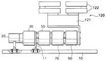
도 2 는 본 발명의 제1실시예에 따른 작업대상물 이송장치의 평단면도로서, 비작동상태를 도시한 것이다.2 is a plan sectional view of a workpiece transport apparatus according to a first embodiment of the present invention, showing a non-operation state.
도 3 은 도 2 의 측면도이다.3 is a side view of FIG. 2.
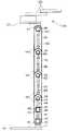
도 4 는 본 발명의 제1실시예에 따른 작업대상물 이송장치가 수직방향으로 상승하는 동작을 도시한 정면도이다.4 is a front view illustrating an operation of raising the workpiece transfer device in the vertical direction according to the first embodiment of the present invention.
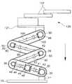
도 5 는 본 발명의 제1실시예에 따른 작업대상물 이송장치가 최대수직높이로 상승된 상태를 도시한 정면도이다.5 is a front view showing a state in which the workpiece transport apparatus according to the first embodiment of the present invention is raised to the maximum vertical height.
도 6 은 본 발명의 제1실시예에 따른 작업대상물 이송장치가 수직으로 하강하는 동작을 도시한 정면도이다.6 is a front view illustrating an operation of vertically descending the workpiece transport apparatus according to the first embodiment of the present invention.
도 7 은 본 발명의 제2실시예에 따른 작업대상물 이송장치의 평단면도로서, 비작동상태를 도시한 것이다.7 is a plan sectional view of a workpiece transport apparatus according to a second embodiment of the present invention, showing a non-operational state.
도 8 은 본 발명의 제2실시예에 따른 작업대상물 이송장치가 수직방향으로 상승하는 동작을 도시한 정면도이다.8 is a front view illustrating an operation of lifting the workpiece transport apparatus in the vertical direction according to the second embodiment of the present invention.
*도면의 주요 부분에 대한 부호의 설명** Description of the symbols for the main parts of the drawings *
10...베이스20...구동모터10
30,50,70,90...링크31,51,71,91...지지축30,50,70,90 ...
35,55,75,95...선회축40,60,80,100...회전축35,55,75,95 ...
120...탑재부120 ...
본 발명은 작업대상물 이송장치에 관한 것으로, 더욱 상세하게는 수직방향으로 승강하여 웨이퍼나 패널, 또는 컴퓨터 하드디스크와 같은 작업대상물을 소정의 위치로 이송시키는데 적합한 작업대상물 이송장치에 관한 것이다.The present invention relates to a workpiece transport apparatus, and more particularly, to a workpiece transport apparatus suitable for transporting a workpiece such as a wafer, a panel, or a computer hard disk to a predetermined position by lifting in a vertical direction.
반도체 또는 전자제품 제조공정에서는 웨이퍼나 하드디스크 등을 소정위치로 이동시키기 위해서 수평 또는 수직방향으로 이동할 수 있는 아암을 가진 장치를 필요로 한다. 도1은 이러한 작업대상물을 수직방향으로 이동시키기 위한 종래기술의 한 예로서, 미국특허 5,993,142에 개시된 장치를 도시한 것이다.BACKGROUND OF THE INVENTION A semiconductor or electronics manufacturing process requires an apparatus having an arm that can move in a horizontal or vertical direction to move a wafer or a hard disk to a predetermined position. 1 illustrates an apparatus disclosed in US Pat. No. 5,993,142 as an example of the prior art for moving such a workpiece in a vertical direction.
이 장치는 베이스(1)에 설치되는 복수의 리드 스크류(2)와 구동 모터(미도시), 중공(中空)을 형성하여 상기 리드 스크류(2)를 수용하는 복수의 수직구조체(3), 수직구조체(3)의 하단에 설치되어 리드 스크류(2)와 나사결합된 엘리베이터(4), 수직구조체(3)의 상단에 마련된 플랜지(5), 수직구조체(3)들의 사이에 배치되며 상기 플랜지(5)에 얹혀져서 설치되는 링크(L1), 이 링크(L1)의 일단에 일렬로 연결된 링크(L2)(L3)들, 그리고 링크(L3)의 종단에 연결된 모터(6)와 엔드 이펙터(end effector)(7)를 구비하여 이루어진다.The apparatus forms a plurality of lead screws (2), a drive motor (not shown), and a plurality of vertical structures (3) for accommodating the lead screws (2) installed in the base (1), vertically. It is installed at the lower end of the structure (3) and is arranged between the lead screw (2) and screwed elevator (4), the flange (5) provided on the top of the vertical structure (3), the vertical structure (3) and the flange ( 5) the link L1 mounted on the link, the links L2 and L3 connected in series with one end of the link L1, and the
베이스(1)에 설치된 구동모터(미도시)가 작동하면, 이 모터에 벨트결합된 리드 스크류(2)가 회전하게 되고, 이 리드 스크류(2)에 의해 나사결합된 엘리베이터(4)를 모터의 회전방향에 따라 상향 또는 하향으로 이동시킨다. 이에 의해 수직구조체(3)는 텔레스코픽하게 수직이동하면서 엔드 이펙터(7)에 놓여진 작업대상물을 소정위치로 이송시키는 것이다.When the drive motor (not shown) installed in the base 1 is operated, the
그러나, 상기와 같이 구성된 종래기술에 따른 장치는 수직구조체가 리드 스크류를 따라 텔레스코픽하게 수직으로 승강하는 구조로 이루어져서 비작동상태에서도 리드 스크류의 높이에 해당하는 만큼의 수직공간을 차지하게 되므로, 비작동시 수직방향으로 많은 공간을 차지하게 되며, 비작동상태에서의 높이에 해당하는 만큼의 이송 불가능한 영역이 존재하는 단점이 있다.However, the device according to the prior art configured as described above has a structure in which the vertical structure is telescopically elevated vertically along the lead screw, thus occupying the vertical space corresponding to the height of the lead screw even in a non-operational state. It occupies a lot of space in the vertical direction at the time, and there is a disadvantage in that an area that cannot be transported corresponds to a height in a non-operating state.
또한, 종래기술의 장치는 그 구조상 많은 부품이 소요하게 되고, 모터와 리드 스크류, 그리고 수직 구조체의 결합이 복잡하게 이루어져서 제작비용과 제작시간이 많이 요구되는 단점이 있다.In addition, the device of the prior art takes a lot of parts in the structure, and the combination of the motor, the lead screw, and the vertical structure has a disadvantage that a lot of manufacturing cost and manufacturing time is required.
본 발명은 상기 문제점을 해결하기 위해 안출된 것으로, 본 발명의 목적은 구조와 작동이 간편하게 이루어지고, 비작동시에는 수직높이가 작게 요구되는 작업대상물 이송장치를 제공하는 것이다.The present invention has been made to solve the above problems, an object of the present invention is to provide a workpiece transfer device that is made simple in structure and operation, the vertical height is small when inactive.
상기 목적을 달성하기 위한 본 발명에 따른 작업대상물 이송장치는 베이스, 베이스에 고정된 지지축, 일단이 지지축에 선회운동 가능하게 연결된 제1링크, 일 단이 제1링크의 타단에 선회운동 가능하게 연결된 제2링크, 제2링크에 연결되어 작업대상물을 탑재하여 이송하는 탑재부, 제1링크를 선회시키는 구동모터, 제1링크에 회전운동 가능하게 설치되어 제1링크의 선회력으로 회전하는 회전축, 일단이 제2링크의 일단에 고정되고 타단이 제1링크의 회전축과 연결되어 회전축의 회전력을 전달받아 제2링크를 선회시키는 선회축을 포함하여 이루어진다.Work object transport apparatus according to the present invention for achieving the above object is a base, a support shaft fixed to the base, the first link is connected to one end pivotally to the support shaft, one end is pivotable to the other end of the first link A second link connected to the second link, a mounting part connected to the second link to mount and transport the workpiece, a driving motor to pivot the first link, a rotational shaft rotatably installed on the first link to rotate by the rotational force of the first link, One end is fixed to one end of the second link and the other end is connected to the rotating shaft of the first link is made of a rotating shaft for receiving the rotational force of the rotating shaft to rotate the second link.
회전축의 양단에는 베벨기어가 각각 형성되고, 지지축의 단부에는 회전축의 일단의 베벨기어와 이물림된 고정 베벨기어가 형성되며, 선회축의 타단에는 회전축의 타단의 베벨기어와 이물림된 선회 베벨기어가 형성됨으로써, 제1링크의 선회에 의해 회전축이 회전하게 되고, 이 회전력에 의해 제2링크에 고정된 선회축이 선회하게 되어 제2링크를 선회시키게 된다.Bevel gears are formed at both ends of the rotating shaft, and one end of the rotating shaft is formed with a bevel gear and a sewed fixed bevel gear, and another end of the rotating shaft is a bevel gear with the other end of the rotating shaft and a beveled turning bevel gear. As a result, the rotating shaft rotates by the turning of the first link, and the rotating shaft fixed to the second link turns by the turning force, thereby turning the second link.
상기 회전축은, 양단에 각각 베벨기어가 형성되며 일단이 지지축의 고정 베벨기어와 이물림된 제1서브회전축과, 양단에 각각 베벨기어가 형성되며 일단이 선회축의 선회 베벨기어와 이물림된 제2서브회전축과, 제1서브회전축과 제2서브회전축의 타단에 형성된 베벨기어와 동시에 이물림된 회전 베벨기어를 구비하고 제1링크에 회전가능하게 설치된 전환축을 포함함으로써, 제1링크의 상방 또는 하방으로의 선회에 따라 제2링크도 동일한 방향으로 상방 또는 하방으로 선회하게 된다.The rotating shaft has a bevel gear formed at both ends thereof, and a first sub-rotation shaft having one end meshed with a fixed bevel gear of the support shaft, and a bevel gear formed at both ends thereof, and one end of which is pivoted with a pivoting bevel gear of the pivot shaft. By including a sub-rotation shaft, a bevel gear formed on the other end of the first and second sub-rotation shaft and the rotating bevel gear is meshed at the same time, and a switching shaft rotatably installed on the first link, the upper or lower of the first link The second link also turns upward or downward in the same direction as it turns.
전환축의 회전 베벨기어와 제1 및 제2 서브회전축의 베벨기어의 잇수비는 1:1 이고, 제2서브회전축의 베벨기어와 선회축의 베벨기어의 잇수비는 2:1 로 되어서, 제2링크의 선회각도가 제1링크의 선회각도의 2배가 되도록 한다. 이에 의해 링크들의 양단은 동일축선을 따라 승강하게 된다.The tooth ratio of the rotating bevel gear of the switching shaft and the bevel gear of the first and second sub-rotating shafts is 1: 1, and the tooth ratio of the bevel gear of the second sub-rotating shaft and the bevel gear of the pivoting shaft is 2: 1, so that the second link The turning angle of is to be twice the turning angle of the first link. As a result, both ends of the links are moved up and down along the same axis.
본 발명의 작업대상물 이송장치는 제2링크에 고정된 선회축과 동축적으로 설치되고 일단은 제1링크에 고정되고 타단은 제2링크로 연장하여 제2링크를 선회 가능하게 지지하는 지지축과, 일단이 제1링크에 고정되어 제2링크를 선회 가능하게 지지하는 지지축과, 제2링크에 회전운동 가능하게 설치되어 제2링크의 선회력으로 회전하는 회전축과, 일단이 탑재부에 고정되고 타단이 제2링크에 설치된 회전축과 연결되어 상기 회전축의 회전력을 전달받아 탑재부를 선회시키는 선회축을 더 포함한다.The workpiece conveying apparatus of the present invention is installed coaxially with a pivot shaft fixed to the second link, one end of which is fixed to the first link and the other end of which extends to the second link to support the second link so as to be pivotable. A support shaft having one end fixed to the first link to pivotally support the second link, a rotation shaft installed rotatably on the second link to rotate with the pivot force of the second link, and one end fixed to the mounting portion and the other end It further includes a pivot shaft connected to the rotary shaft installed in the second link to receive the rotational force of the rotary shaft to pivot the mounting portion.
제2링크에 설치된 회전축의 양단에는 각각 베벨기어가 형성되고, 제2링크를 지지하는 지지축의 타단에는 상기 회전축의 일단의 베벨기어와 이물림된 고정 베벨기어가 형성되며, 탑재부에 고정된 선회축의 타단에는 상기 회전축의 타단의 베벨기어와 이물림된 선회 베벨기어가 형성됨으로써, 제2링크의 선회에 의해 상기 회전축이 회전하게 되고, 이 회전력에 의해 선회축이 탑재부와 함께 선회하게 된다.Bevel gears are formed at both ends of the rotary shaft installed in the second link, respectively, and bevel gears of one end of the rotary shaft and the fixed bevel gears are formed at the other ends of the support shaft supporting the second link, The other end of the rotating bevel gear is formed in the other end of the rotating bevel gear and the bevel gear, the rotary shaft is rotated by the rotation of the second link, the rotary shaft is rotated with the mounting portion by this rotational force.
제2링크에 설치된 회전축의 베벨기어와 제1링크에 고정된 지지축의 베벨기어의 잇수비는 1:1로 되고, 상기 회전축의 베벨기어와 탑재부에 고정된 선회축의 베벨기어의 잇수비는 1:2 로 되어서, 탑재부의 선회각도가 제2링크의 선회각도의 1/2배가 되도록 한다. 이에 의해 탑재부는 수평을 유지한 채로 승강하게 된다.The tooth ratio of the bevel gear of the rotating shaft installed in the 2nd link and the bevel gear of the support shaft fixed to the 1st link becomes 1: 1, and the tooth ratio of the bevel gear of the rotating shaft and the bevel gear of the rotating shaft fixed to the mounting part is 1: It is set to 2 so that the rotation angle of the mounting portion may be 1/2 times the rotation angle of the second link. As a result, the mounting portion is moved up and down while keeping the horizontal.
본 발명의 다른 실시예로서, 상기 제2링크는, 제1링크와 제2링크의 결합과 동일한 방식으로 연속적으로 결합된 다수의 서브링크를 포함하고 탑재부는 마지막 서브링크에 설치되도록 하여서, 탑재부가 더욱 긴 수직이동거리를 갖게 된다.In another embodiment of the present invention, the second link includes a plurality of sublinks continuously coupled in the same manner as the combination of the first link and the second link, and the mounting portion is installed on the last sublink, so that the mounting portion It will have longer vertical travel.
이하에서는 첨부된 도면을 참조하여 본 발명에 대한 바람직한 실시예를 상세 하게 설명한다.Hereinafter, with reference to the accompanying drawings will be described in detail a preferred embodiment of the present invention.
도 2 와 도 3 은 비작동상태로 놓여있는 본 발명의 제1실시예에 따른 작업대상물 이송장치의 평단면도와 측면도를 도시한 것이다. 이에 도시된 바와 같이, 제1실시예에 따른 작업대상물 이송장치는 베이스(10)에 고정되며 감속기어(미도시)를 포함하는 구동모터(20), 구동모터(20)의 감속기어에 결합되는 제1링크(30), 제1링크(30)에 순차적으로 병렬로 배치되는 복수의 제2 내지 제4링크(50)(70)(90), 그리고 선회아암(121)과 복수의 이송아암(122)을 구비하며 가장 마지막에 배치된 제4링크(90)에 결합되는 탑재부(120)를 포함한다. 링크(30)(50)(70)(90)들은 내부에 공간이 형성된 직방체 또는 원기둥으로 이루어진다.2 and 3 show a cross-sectional plan view and a side view of a workpiece transport apparatus according to a first embodiment of the present invention in an inoperative state. As shown in the drawing, the workpiece transport apparatus according to the first embodiment is fixed to the
본 발명에서는 링크의 갯수를 4개로 한정하였지만, 이는 설명의 편의상 정해진 것으로, 링크를 최소한 2개 이상으로 구성하기만 하면 본 발명의 목적을 달성할 수 있게 된다. 2개의 링크로 구성된 작업대상물 이송장치는 제2실시예에서 설명할 것이다.In the present invention, the number of links is limited to four, but this is defined for convenience of description, and it is possible to achieve the object of the present invention by simply configuring at least two links. The workpiece transport apparatus composed of two links will be described in the second embodiment.
베이스(10)에 고정된 구동모터(20)는 감속기어의 회전축(미도시)이 제1링크(30)의 선단의 외측면에 결합됨으로써 제1링크(30)를 그 선단을 중심으로하여 선회시키게 된다. 구동모터(20)로는 AC 서보모터가 사용된다.The driving
제1링크(30)의 내부공간에는 제1링크(30)와 이웃하여 병렬로 배치된 제2링크(50)를 선회시키기 위해 지지축(31), 선회축(35), 그리고 회전축(40)이 설치된다.In the inner space of the
지지축(31)은 구동모터(20)를 마주하여 배치되며, 제1링크(30)를 관통하여 베이스(10)에 고정된 브라켓(11)에 결합됨으로써 고정된다. 지지축(31)의 단부에는 고정 베벨기어(32)가 형성되어 있으며, 지지축(31)이 제1링크(30)를 관통하는 부위에는 베어링(49)이 설치되어 제1링크(30)를 선회 가능하게 지지한다.The
선회축(35)은 제1링크(30)의 종단에 배치되며, 제1링크(30)를 관통하여 제2링크(50)의 선단의 외측면에 고정됨으로써 제2링크(50)와 일체로 선회하게 된다. 선회축(35)의 단부에는 선회 베벨기어(36)가 형성되어 있다. 선회축(35)의 내부는 속이 빈 중공부(中空部)(37)로 이루어진다.The
회전축(40)은 제1서브회전축(41)과 제2서브회전축(44), 그리고 이 제1 및 제2서브회전축(41)(44)을 연결하며 회전방향을 전환시키는 전환축(47)을 구비한다. 전환축(47)은 제1링크(30)에 회전 가능하게 설치되며, 그 단부에는 회전 베벨기어(48)가 형성되어 있다.The rotating
제1서브회전축(41)의 양단에는 각각 지지축(31)의 고정 베벨기어(32)와 전환축(47)의 회전 베벨기어(48)에 이물림된 베벨기어(42)(43)가 형성되어 있으며, 제2서브회전축(44)의 양단에는 각각 전환축(47)의 회전 베벨기어(48)와 선회축(35)의 선회 베벨기어(36)에 이물림된 베벨기어(45)(46)가 형성되어 있다. 제1링크(30)의 내부에는 상기 제1서브회전축(41)과 제2서브회전축(44)을 회전 가능하게 지지하기 위해 축수(軸受)부재(110)들이 설치되어 있다. 이 축수부재(110)는 제1링크(30)에 볼트고정되며, 회전축(41)(44)들이 관통하는 부위에는 베어링이 배치됨으로써 제1 및 제2서브회전축(41)(44)들을 회전가능하게 지지하게 된다.Bevel gears 42 and 43 are formed at both ends of the
지지축(31)의 베벨기어(32), 제1 및 제2서브회전축(41)(44)의 베벨기어(42)(43)(45), 그리고 전환축(47)의 베벨기어(48)는 각각 1:1의 동일한 잇수비로 기어결합되며, 제2서브회전축(44)의 베벨기어(46)와 선회축(35)의 베벨기어(36)는 2:1의 잇수비로 기어결합된다. 이러한 기어비에 의해서 도 4 에서와 같이, 제1링크(30)가 θ만큼 선회하면 제2링크(50)는 그 2배인 2θ 만큼 선회하게 된다.Bevel gears 32 of the
제1링크(30)의 경우와 마찬가지로, 제2링크(50)의 내부공간에는 제2링크(50)와 이웃하여 병렬로 배치된 제3링크(70)를 선회시키기 위해 지지축(51), 선회축(55), 그리고 회전축(60)이 설치된다.As in the case of the
지지축(51)은 제2링크(50)의 선단에서 제2링크(50)와 제1링크(30)의 선회축(35)을 관통하여 제1링크(30)의 내부에 볼트결합됨으로써 고정된다. 지지축(51)의 단부에는 고정 베벨기어(52)가 형성되어 있으며, 지지축(51)이 상기 제2링크(50)와 제1링크(30)의 선회축(35)을 관통하는 부위에는 베어링(49)이 설치되어 제2링크(50)를 선회 가능하게 지지한다.The
선회축(55)은 제2링크(50)의 종단에 배치되며, 제2링크(50)를 관통하여 제3링크(70)의 선단의 외측면에 고정됨으로써 제3링크(70)와 일체로 선회하게 된다. 선회축(55)의 단부에는 선회 베벨기어(56)가 형성되어 있다. 선회축(55)의 내부는 속이 빈 중공부(57)로 이루어진다.The
회전축(60)은 제1링크(30)에서와는 달리, 하나의 긴 봉형으로 이루어지며, 그 양단에는 각각 지지축(51)의 베벨기어(52)와 선회축(55)의 베벨기어(56)에 이물림된 회전 베벨기어(61)(62)가 형성되어 있다. 제2링크(50)의 내부에는 상기 회전 축(60)을 회전 가능하게 지지하기 위해 제1링크(30)의 것들과 동일한 축수부재(110)들이 설치되어 있다.Unlike the
지지축(51)의 베벨기어(52), 회전축(60)의 베벨기어(61)(62), 그리고 선회축(55)의 베벨기어(56)는 각각 1:1의 동일한 잇수비로 기어결합된다. 이러한 기어비에 의해서 도 4 에서와 같이, 제2링크(50)가 2θ 만큼 선회하면 제3링크(70)도 동일하게 2θ 만큼 선회하게 된다.The
제3링크(70)의 내부공간에는 제3링크(70)와 이웃하여 병렬로 배치된 제4링크(90)를 선회시키기 위해 제2링크(50)와 동일한 구조로 이루어진 지지축(71), 선회축(75), 그리고 회전축(80)이 설치된다.In the inner space of the
지지축(71)은 제3링크(70)의 선단에서 제3링크(70)와 제2링크(50)의 선회축(55)을 관통하여 제2링크(50)의 내부에 볼트결합됨으로써 고정된다. 지지축(71)의 단부에는 고정 베벨기어(72)가 형성되어 있으며, 지지축(71)이 상기 제3링크(70)와 제2링크(50)의 선회축(55)을 관통하는 부위에는 베어링(49)이 설치되어 제3링크(70)를 선회가능하게 지지한다.The
선회축(75)은 제3링크(70)의 종단에 배치되며, 제3링크(70)를 관통하여 제4링크(90)의 선단의 외측면에 고정됨으로써 제4링크(90)와 일체로 선회하게 된다. 선회축(75)의 단부에는 선회 베벨기어(76)가 형성되어 있으며, 선회축(75)의 내부는 속이 빈 중공부(77)로 이루어진다.The
회전축(80)의 양단에는 각각 지지축(71)의 베벨기어(72)와 선회축(75)의 베벨기어(76)에 이물림된 회전 베벨기어(81)(82)가 형성되어 있다. 제3링크(70)의 내 부에도 회전축(80)을 회전 가능하게 지지하기 위해 축수부재(110)들이 설치되어 있다. 지지축(71)의 베벨기어(72), 회전축(80)의 베벨기어(81)(82), 그리고 선회축(75)의 베벨기어(76)는 각각 1:1의 동일한 잇수비로 기어결합된다. 이러한 기어비에 의해서 도 4 에서와 같이, 제3링크(70)가 2θ 만큼 선회하면 제4링크(90)도 동일하게 2θ 만큼 선회하게 된다.At both ends of the
제2 및 제3링크(50)(70)의 경우와 마찬가지로, 제4링크(90)의 내부공간에는 이 제4링크(90)의 종단에 결합된 탑재부(120)를 수평면과 평행한 상태를 유지하면서 수직방향으로 이동시키기 위해 지지축(91), 선회축(95), 그리고 회전축(100)이 설치된다.As in the case of the second and
지지축(91)은 제4링크(90)의 선단에서 제4링크(90)와 제3링크(70)의 선회축(75)을 관통하여 제3링크(70)의 내부에 볼트결합됨으로써 고정된다. 지지축(91)의 단부에는 고정 베벨기어(92)가 형성되어 있으며, 지지축(91)이 상기 제4링크(90)와 제3링크(70)의 선회축(75)을 관통하는 부위에는 베어링(49)이 설치되어 제4링크(90)를 선회가능하게 지지한다.The
선회축(95)은 제4링크(90)의 종단에 배치되며, 제4링크(90)를 관통하여 탑재부(120)의 선회아암(121)에 고정됨으로써 탑재부(120)와 일체로 선회하게 된다. 선회축(95)의 단부에는 선회 베벨기어(96)가 형성되어 있으며, 선회축(95)이 제4링크(90)를 관통하는 부위에는 베어링(49)이 설치되어 탑재부(120)를 회전 가능하게 지지하게 된다.The
회전축(100)의 양단에는 각각 지지축(91)의 베벨기어(92)와 선회축(95)의 베 벨기어(96)에 이물림된 회전 베벨기어(101)(102)가 형성되어 있다. 제4링크(90)의 내부에도 회전축(100)을 회전 가능하게 지지하기 위해 축수부재(110)들이 설치되어 있다. 지지축(91)의 베벨기어(92)와 회전축(100)의 베벨기어(101)는 1:1의 동일한 잇수비로 기어결합되며, 회전축(100)의 베벨기어(102)와 선회축(95)의 베벨기어(96)는 1:2의 잇수비로 기어결합된다. 이러한 기어비에 의해서 도 4 에서와 같이, 제4링크(90)가 2θ 만큼 선회하면 탑재부(120)는 수평면과 평행하게 유지되면서 그 1/2배인 θ 만큼 선회하게 된다.Rotating
도 4 내지 도 6 은 상기와 같이 구성된 본 발명의 제1실시예에 따른 작업대상물 이송장치의 승하강동작을 도시한 것으로, 이하에서는 이 도면들을 참조하여 본 발명의 작용에 대해 설명하고자 한다.4 to 6 illustrate the lifting and lowering operation of the workpiece transport apparatus according to the first embodiment of the present invention configured as described above. Hereinafter, the operation of the present invention will be described with reference to these drawings.
도 4 에 도시된 바와 같이, 탑재부(120)를 소요의 높이까지 수직방향으로 상승시키기 위해 링크들을 상방으로 전개시키는 방향으로 구동모터(20)를 작동시키면, 감속기어(미도시)에 연결된 제1링크(30)가 소요높이에 대응하는 일정각도(θ) 만큼 상방으로 선회하게 된다. 이 때, 지지축(31)은 브라켓(11)에 의해 베이스(10)에 고정되어 있으므로(도 2 참조), 제1링크(30)의 선회에 의해 그 내부에 설치된 제1서브회전축(41)의 베벨기어(42)가 지지축(31)의 베벨기어(32)를 따라 도 4 에 표시된 화살표방향으로 회전하게 된다. 제1서브회전축(41)의 회전에 의해 전환축(47)은 도 4 에 표시된 화살표방향으로 회전하면서 제2서브회전축(44)을 제1서브회전축(41)과 반대방향으로 회전시키게 된다.As shown in FIG. 4, when the driving
이 축(41)(44)(47)들의 회전력에 의해 제2서브회전축(44)의 베벨기어(46)에 이물림되어 있는 베벨기어(36)를 가진 선회축(35)을 선회시킴으로써 선회축(35)과 결합되어 있는 제2링크(50)를 지지축(51)을 중심으로하여 상방으로 선회하게 된다. 제2링크(50)의 선회각도는 제2서브회전축(44)의 베벨기어(46)와 선회축(35)의 베벨기어(36)가 2:1의 잇수비로 기어결합되므로 제1링크(30)의 선회각도(θ)의 2배인 2θ로 된다.By turning the
제2링크(50)의 내부에 설치된 회전축(60)의 베벨기어(61)는 지지축(51)의 베벨기어(52)에 이물림되어 있으므로, 제2링크(50)가 선회하면 회전축(60)은 제2링크(50)와 함께 선회함과 동시에 도 4 에 표시된 화살표방향으로 회전하게 된다. 이 회전축(60)의 회전력은 회전축(60)의 베벨기어(62)에 이물림되어 있는 선회축(55)의 베벨기어(56)에 전달되어 선회축(55)을 선회시키게 된다. 이에 의해 선회축(55)과 결합되어 있는 제3링크(70)는 지지축(71)을 중심으로하여 상방으로 선회하게 된다. 제3링크(70)의 선회각도는 제2링크(50)에 설치된 베벨기어들이 모두 1:1의 기어비로 기어결합되어 있으므로 제2링크(50)와 동일하게 2θ로 된다.Since the
제4링크(90)도 이와 마찬가지 방식으로 선회하게 된다. 즉, 제3링크(70)가 선회하면, 제3링크(70)의 내부에 설치된 회전축(80)은 제3링크(70)와 함께 선회함과 동시에 도 4 에 표시된 화살표방향으로 회전하게 된다. 이 회전축(80)의 회전에 의해 선회축(75)이 선회하게 되고, 이에 의해 선회축(75)과 결합되어 있는 제4링크(90)도 지지축(91)을 중심으로하여 상방으로 선회하게 된다. 제4링크(90)의 선회각도는 제3링크(70)에 설치된 베벨기어들이 모두 1:1의 기어비로 기어결합되어 있으므로 제3링크(70)와 동일하게 2θ로 된다.The
제4링크(90)가 선회하면, 이 제4링크(90)의 내부에 설치된 회전축(100)도 상기와 마찬가지 방식으로 도 4 에 표시된 화살표방향으로 회전하게 된다. 이 회전축(100)의 회전력은 회전축(100)의 베벨기어(102)와 선회축(95)의 베벨기어(96)에 의해 선회축(95)에 전달되어서, 이 선회축(95)에 결합된 탑재부(120)의 선회아암(121)을 선회시키게 된다. 이에 의해 탑재부(120)가 선회하게 되는 것이다. 탑재부(120)의 선회각도는 베벨기어(92)와 (101)이 1:1의 기어비로 결합되고, 베벨기어(102)와 (96)이 1:2의 기어비로 결합되므로, 제4링크(90)의 선회각도(2θ)의 1/2배인 θ로 된다.When the
상기와 같은 구조와 기어비에 의해 각 링크들이 승강할 때, 각 링크들의 단부들은 동일축선(Y-Y)을 따라서 이동하게 된다. 따라서, 링크들이 어떠한 각도로 위치하더라도 링크들과 탑재부는 도 4 와 같은 자세를 유지하기 때문에, 탑재부(120)는 수평면과 평행을 이루면서 수직방향으로 승강하게 되는 것이다.When each link is lifted and lowered by the above structure and gear ratio, the ends of the links move along the same axis (Y-Y). Therefore, since the links and the mounting part maintain the posture as shown in FIG. 4 no matter where the links are positioned at any angle, the mounting
도 5 는 본 발명에 따른 작업대상물 이송장치가 수직상방으로 최대높이까지 펼쳐된 상태를 도시한 것이다. 이 상태에서 제1링크(30)와 탑재부(120)의 회동각도(θ)는 90°가 되고, 제2 내지 제4링크(50)(70)(90)의 회동각도(2θ)는 180˚로 된다.5 is a view illustrating a state in which the workpiece transport apparatus according to the present invention is unfolded up to a maximum height vertically. In this state, the rotation angle θ of the
도 6 은 작업대상물의 이송작업을 완료하여 이송장치를 비작동상태로 전환시키는 동작을 도시한 것이다. 구동모터(20)가 링크들을 하강시키는 방향으로 회전하면, 도 6 에 화살표로 표시된 바와 같이, 각 회전축들이 도 4 의 경우와 반대방향으로 회전하게 되어서 링크들이 하향으로 이동하게 된다.6 illustrates an operation of switching the transfer device to an inoperative state by completing a transfer operation of the workpiece. When the
도 7 과 도 8 은 본 발명의 제2실시예에 따른 작업대상물 이송장치를 도시한 것이다. 이 실시예는 본 발명의 작업대상물 이송장치가 최소한의 갯수인 두 개의 링크에 의해 구성될 수 있다는 것을 보여주기 위한 것이다. 도 7 에 도시된 제1링크(30A)와 이 링크(30A)의 내부에 설치된 축들, 그리고 기어비들은 도 2 에 도시된 제1링크(30)와 그 내부에 설치된 축들, 그리고 기어비들과 동일하게 구성된다. 또한, 도 7 에 도시된 제2링크(90A)와 그 내부에 설치된 축들, 그리고 기어비들은 도 2 에 도시된 제4링크(90)와 그 내부에 설치된 축들, 그리고 기어비들과 동일하게 구성된다. 따라서, 링크들을 제외한 다른 요소들의 참조번호는 제1실시예에서와 동일하게 부여하였다.7 and 8 illustrate a workpiece transport apparatus according to a second embodiment of the present invention. This embodiment is intended to show that the workpiece transport apparatus of the present invention can be constituted by two links of a minimum number. The
도 8 은 도 4 에 대응하는 도면으로서, 제1 및 제2링크(30A)(90A)가 상방으로 선회하여 탑재부(120)를 수평면에 평행하게 수직상방으로 이동시키는 것을 도시한 것이다. 이 제2실시예에 따른 작업대상물 이송장치의 작동은 제1실시예에서와 동일하므로 더 이상의 설명은 생략한다.FIG. 8 is a view corresponding to FIG. 4, in which the first and
이상에서 설명한 바와 같이, 본 발명에 따른 작업대상물 이송장치는 적어도 2개 이상의 링크들이 병렬로 배치되고 신축가능하게 연결됨으로써 비작업시 설치공간을 작게 차지하게 되어 작업성이 개선되며, 작업대상물의 이송영역을 높이는 효과가 있다. 또한, 장치의 구조가 간단하고 부품의 수가 적어지게 되므로 제작비용과 제작시간을 감소시킬 수 있는 효과가 있다.
As described above, the workpiece transport apparatus according to the present invention is at least two or more links are arranged in parallel and is connected to the flexible to occupy a small installation space during non-working workability is improved, the transport of the workpiece It is effective to increase the area. In addition, since the structure of the device is simple and the number of parts is reduced, the manufacturing cost and manufacturing time can be reduced.
Claims (10)
Translated fromKoreanPriority Applications (3)
| Application Number | Priority Date | Filing Date | Title |
|---|---|---|---|
| KR1020000009590AKR100592957B1 (en) | 2000-02-26 | 2000-02-26 | Work Object Transfer Device |
| US09/629,853US6478531B1 (en) | 2000-02-26 | 2000-08-01 | Article transfer apparatus |
| JP2000233674AJP2001239482A (en) | 2000-02-26 | 2000-08-01 | Work object transfer device |
Applications Claiming Priority (1)
| Application Number | Priority Date | Filing Date | Title |
|---|---|---|---|
| KR1020000009590AKR100592957B1 (en) | 2000-02-26 | 2000-02-26 | Work Object Transfer Device |
Publications (2)
| Publication Number | Publication Date |
|---|---|
| KR20010084503A KR20010084503A (en) | 2001-09-06 |
| KR100592957B1true KR100592957B1 (en) | 2006-06-23 |
Family
ID=19650360
Family Applications (1)
| Application Number | Title | Priority Date | Filing Date |
|---|---|---|---|
| KR1020000009590AExpired - Fee RelatedKR100592957B1 (en) | 2000-02-26 | 2000-02-26 | Work Object Transfer Device |
Country Status (3)
| Country | Link |
|---|---|
| US (1) | US6478531B1 (en) |
| JP (1) | JP2001239482A (en) |
| KR (1) | KR100592957B1 (en) |
Cited By (1)
| Publication number | Priority date | Publication date | Assignee | Title |
|---|---|---|---|---|
| KR101110876B1 (en)* | 2009-06-30 | 2012-02-15 | (주)화담알앤알 | Industrial robot |
Families Citing this family (14)
| Publication number | Priority date | Publication date | Assignee | Title |
|---|---|---|---|---|
| KR20040015536A (en)* | 2002-08-13 | 2004-02-19 | 삼성전자주식회사 | Multi-articulated robot |
| US20060249716A1 (en)* | 2003-10-30 | 2006-11-09 | Rincoe Richard G | Method of maneuvering a mechanical arm assembly relative to a base support |
| US7152456B2 (en)* | 2004-01-14 | 2006-12-26 | Romer Incorporated | Automated robotic measuring system |
| US7814811B2 (en)* | 2004-08-25 | 2010-10-19 | Kabushiki Kaisha Yaskawa Denki | Articulated robot |
| JP4336831B2 (en)* | 2004-11-24 | 2009-09-30 | 東芝機械株式会社 | Industrial robot |
| JP2008254138A (en)* | 2007-04-06 | 2008-10-23 | Yaskawa Electric Corp | Articulated robot |
| DE102007050905B4 (en)* | 2007-10-23 | 2015-08-20 | Schaeffler Technologies AG & Co. KG | Handling device with three-ring bearing between two outer pivot arms and a platform |
| EP2716419A4 (en)* | 2011-06-01 | 2015-04-08 | Yaskawa Denki Seisakusho Kk | MULTI-JOINT ROBOT |
| US20130309048A1 (en)* | 2012-05-16 | 2013-11-21 | Lam Research Ag | Apparatus and method for transporting wafer-shaped articles |
| CN103659411B (en)* | 2012-08-31 | 2016-03-09 | 鸿富锦精密工业(深圳)有限公司 | Turning device |
| CN109095045A (en)* | 2018-07-20 | 2018-12-28 | 湖南瑭桥科技发展有限公司 | A kind of novel rod-type garbage truck manipulator folding arm directing controller |
| CN109877816A (en)* | 2019-03-15 | 2019-06-14 | 安徽工业大学 | A single-degree-of-freedom multi-joint mast system and lifting method |
| CN111890407A (en)* | 2020-07-10 | 2020-11-06 | 杭州景业智能科技有限公司 | Manipulator for nuclear industry |
| KR102830447B1 (en)* | 2023-02-15 | 2025-07-08 | 경북대학교 산학협력단 | Inter-floor Material Handling Lift |
Citations (6)
| Publication number | Priority date | Publication date | Assignee | Title |
|---|---|---|---|---|
| JPS63272474A (en)* | 1987-04-30 | 1988-11-09 | 日本電子株式会社 | Sample conveying arm |
| JPH02100887A (en)* | 1988-10-07 | 1990-04-12 | Toshiba Corp | Transfer equipment |
| KR940007711Y1 (en)* | 1988-11-15 | 1994-10-24 | 다이와 세이꼬오 가부시끼가이샤 | Mechanism for preventing rotor from rotating in reverse direction |
| JPH08245190A (en)* | 1995-03-09 | 1996-09-24 | Yamaha Motor Co Ltd | Lifting gear |
| JPH09102526A (en)* | 1995-10-05 | 1997-04-15 | Kokusai Electric Co Ltd | Substrate transfer device in vacuum |
| JPH09141589A (en)* | 1995-11-17 | 1997-06-03 | Yaskawa Electric Corp | Wrist mechanism of articulated robot |
Family Cites Families (2)
| Publication number | Priority date | Publication date | Assignee | Title |
|---|---|---|---|---|
| JPH0224075A (en)* | 1988-07-13 | 1990-01-26 | Mitsubishi Electric Corp | Industrial robot |
| US5993142A (en) | 1997-07-10 | 1999-11-30 | Genmark Automation, Inc. | Robot having multiple degrees of freedom in an isolated environment |
- 2000
- 2000-02-26KRKR1020000009590Apatent/KR100592957B1/ennot_activeExpired - Fee Related
- 2000-08-01JPJP2000233674Apatent/JP2001239482A/enactivePending
- 2000-08-01USUS09/629,853patent/US6478531B1/ennot_activeExpired - Fee Related
Patent Citations (6)
| Publication number | Priority date | Publication date | Assignee | Title |
|---|---|---|---|---|
| JPS63272474A (en)* | 1987-04-30 | 1988-11-09 | 日本電子株式会社 | Sample conveying arm |
| JPH02100887A (en)* | 1988-10-07 | 1990-04-12 | Toshiba Corp | Transfer equipment |
| KR940007711Y1 (en)* | 1988-11-15 | 1994-10-24 | 다이와 세이꼬오 가부시끼가이샤 | Mechanism for preventing rotor from rotating in reverse direction |
| JPH08245190A (en)* | 1995-03-09 | 1996-09-24 | Yamaha Motor Co Ltd | Lifting gear |
| JPH09102526A (en)* | 1995-10-05 | 1997-04-15 | Kokusai Electric Co Ltd | Substrate transfer device in vacuum |
| JPH09141589A (en)* | 1995-11-17 | 1997-06-03 | Yaskawa Electric Corp | Wrist mechanism of articulated robot |
Cited By (1)
| Publication number | Priority date | Publication date | Assignee | Title |
|---|---|---|---|---|
| KR101110876B1 (en)* | 2009-06-30 | 2012-02-15 | (주)화담알앤알 | Industrial robot |
Also Published As
| Publication number | Publication date |
|---|---|
| JP2001239482A (en) | 2001-09-04 |
| KR20010084503A (en) | 2001-09-06 |
| US6478531B1 (en) | 2002-11-12 |
Similar Documents
| Publication | Publication Date | Title |
|---|---|---|
| KR100592957B1 (en) | Work Object Transfer Device | |
| JP5847393B2 (en) | Transfer robot | |
| TWI581929B (en) | Substrate transfer robot and its operation method | |
| WO2010041562A1 (en) | Substrate transfer robot and system | |
| JP5078738B2 (en) | Robot for workpiece transfer | |
| JPWO2016189565A1 (en) | Horizontal articulated robot | |
| JP2004090186A (en) | Clean transfer robot | |
| JP4618252B2 (en) | Articulated robot | |
| JP4276534B2 (en) | Transfer robot | |
| JP4004231B2 (en) | Platform leveling device | |
| JPH106258A (en) | Thin form work conveying robot | |
| KR102340634B1 (en) | Apparatus for Transferring Substrate | |
| JP4715952B2 (en) | Frogleg type transfer equipment | |
| JP3488393B2 (en) | Articulated robot device | |
| JP4048142B2 (en) | Arm type robot | |
| KR100530382B1 (en) | Pick and Place for ROM write handler | |
| JP2011190094A (en) | Lifting device | |
| JP5474328B2 (en) | Substrate transfer robot | |
| JP6322318B2 (en) | Transport device | |
| KR100754878B1 (en) | Board Transfer Robot | |
| JP6417444B2 (en) | Transport device | |
| TWI623397B (en) | Horizontal articulated robot | |
| JP2009184078A (en) | Transfer robot | |
| JP6144978B2 (en) | Transport device | |
| JP2000061829A (en) | Surface polishing device with internal gear elevating mechanism |
Legal Events
| Date | Code | Title | Description |
|---|---|---|---|
| PA0109 | Patent application | St.27 status event code:A-0-1-A10-A12-nap-PA0109 | |
| R18-X000 | Changes to party contact information recorded | St.27 status event code:A-3-3-R10-R18-oth-X000 | |
| PG1501 | Laying open of application | St.27 status event code:A-1-1-Q10-Q12-nap-PG1501 | |
| PN2301 | Change of applicant | St.27 status event code:A-3-3-R10-R13-asn-PN2301 St.27 status event code:A-3-3-R10-R11-asn-PN2301 | |
| R18-X000 | Changes to party contact information recorded | St.27 status event code:A-3-3-R10-R18-oth-X000 | |
| R18-X000 | Changes to party contact information recorded | St.27 status event code:A-3-3-R10-R18-oth-X000 | |
| R17-X000 | Change to representative recorded | St.27 status event code:A-3-3-R10-R17-oth-X000 | |
| R18-X000 | Changes to party contact information recorded | St.27 status event code:A-3-3-R10-R18-oth-X000 | |
| A201 | Request for examination | ||
| PA0201 | Request for examination | St.27 status event code:A-1-2-D10-D11-exm-PA0201 | |
| PN2301 | Change of applicant | St.27 status event code:A-3-3-R10-R13-asn-PN2301 St.27 status event code:A-3-3-R10-R11-asn-PN2301 | |
| PN2301 | Change of applicant | St.27 status event code:A-3-3-R10-R13-asn-PN2301 St.27 status event code:A-3-3-R10-R11-asn-PN2301 | |
| D13-X000 | Search requested | St.27 status event code:A-1-2-D10-D13-srh-X000 | |
| D14-X000 | Search report completed | St.27 status event code:A-1-2-D10-D14-srh-X000 | |
| E701 | Decision to grant or registration of patent right | ||
| PE0701 | Decision of registration | St.27 status event code:A-1-2-D10-D22-exm-PE0701 | |
| GRNT | Written decision to grant | ||
| PR0701 | Registration of establishment | St.27 status event code:A-2-4-F10-F11-exm-PR0701 | |
| PR1002 | Payment of registration fee | St.27 status event code:A-2-2-U10-U11-oth-PR1002 Fee payment year number:1 | |
| PG1601 | Publication of registration | St.27 status event code:A-4-4-Q10-Q13-nap-PG1601 | |
| PR1001 | Payment of annual fee | St.27 status event code:A-4-4-U10-U11-oth-PR1001 Fee payment year number:4 | |
| FPAY | Annual fee payment | Payment date:20100412 Year of fee payment:5 | |
| PR1001 | Payment of annual fee | St.27 status event code:A-4-4-U10-U11-oth-PR1001 Fee payment year number:5 | |
| R17-X000 | Change to representative recorded | St.27 status event code:A-5-5-R10-R17-oth-X000 | |
| LAPS | Lapse due to unpaid annual fee | ||
| PC1903 | Unpaid annual fee | St.27 status event code:A-4-4-U10-U13-oth-PC1903 Not in force date:20110617 Payment event data comment text:Termination Category : DEFAULT_OF_REGISTRATION_FEE | |
| PC1903 | Unpaid annual fee | St.27 status event code:N-4-6-H10-H13-oth-PC1903 Ip right cessation event data comment text:Termination Category : DEFAULT_OF_REGISTRATION_FEE Not in force date:20110617 | |
| R18-X000 | Changes to party contact information recorded | St.27 status event code:A-5-5-R10-R18-oth-X000 |