KR100590681B1 - Switching Time Determination Method for Time Delay Compensation of TDD Optical Repeater in WiBro System and TDD Optical Repeater - Google Patents
Switching Time Determination Method for Time Delay Compensation of TDD Optical Repeater in WiBro System and TDD Optical RepeaterDownload PDFInfo
- Publication number
- KR100590681B1 KR100590681B1KR1020040085715AKR20040085715AKR100590681B1KR 100590681 B1KR100590681 B1KR 100590681B1KR 1020040085715 AKR1020040085715 AKR 1020040085715AKR 20040085715 AKR20040085715 AKR 20040085715AKR 100590681 B1KR100590681 B1KR 100590681B1
- Authority
- KR
- South Korea
- Prior art keywords
- signal
- time
- transmission signal
- frame
- optical repeater
- Prior art date
- Legal status (The legal status is an assumption and is not a legal conclusion. Google has not performed a legal analysis and makes no representation as to the accuracy of the status listed.)
- Expired - Fee Related
Links
Images


Classifications
- H—ELECTRICITY
- H04—ELECTRIC COMMUNICATION TECHNIQUE
- H04B—TRANSMISSION
- H04B17/00—Monitoring; Testing
- H04B17/40—Monitoring; Testing of relay systems
- H—ELECTRICITY
- H04—ELECTRIC COMMUNICATION TECHNIQUE
- H04B—TRANSMISSION
- H04B10/00—Transmission systems employing electromagnetic waves other than radio-waves, e.g. infrared, visible or ultraviolet light, or employing corpuscular radiation, e.g. quantum communication
- H04B10/29—Repeaters
Landscapes
- Physics & Mathematics (AREA)
- Electromagnetism (AREA)
- Engineering & Computer Science (AREA)
- Computer Networks & Wireless Communication (AREA)
- Signal Processing (AREA)
- Mobile Radio Communication Systems (AREA)
Abstract
Translated fromKoreanDescription
Translated fromKorean도 1은 와이브로 시스템을 개략적으로 나타낸 구성도,1 is a schematic view showing a WiBro system;
도 2는 와이브로를 통하여 데이터를 전송하는 경우에 있어서 전송 신호의 프레임 구조를 나타낸 도면,2 is a diagram illustrating a frame structure of a transmission signal when data is transmitted through WiBro;
도 3은 본 발명의 바람직한 실시예에 따른 TDD 광중계기의 내부 구성을 나타낸 블록 구성도,3 is a block diagram showing an internal configuration of a TDD optical repeater according to a preferred embodiment of the present invention;
도 4는 와이브로를 통하여 데이터를 전송하는 경우에 있어서 전송 신호 프레임의 프리앰블 시간 구조를 나타낸 도면,4 is a diagram illustrating a preamble time structure of a transmission signal frame when data is transmitted through WiBro;
도 5는 와이브로를 통하여 데이터를 전송하는 경우에 있어서 전송 신호를 자기 상관 시킨 결과 출력된 신호 파형을 표시한 예시 화면,5 is an exemplary screen showing a signal waveform output as a result of autocorrelation of a transmission signal in the case of transmitting data through WiBro;
도 6은 본 발명의 바람직한 실시예에 따른 TDD 광중계기의 스위치 제어부의 내부 구성을 나타낸 블록 구성도,6 is a block diagram showing an internal configuration of a switch control unit of a TDD optical repeater according to a preferred embodiment of the present invention;
도 7은 본 발명의 바람직한 실시예에 따른 TDD 광중계기의 시간 지연 보상을 위한 스위칭 시간 결정 방법을 나타낸 순서도이다.7 is a flowchart illustrating a switching time determination method for time delay compensation of a TDD optical repeater according to a preferred embodiment of the present invention.
<도면의 주요 부분에 대한 부호의 설명><Explanation of symbols for the main parts of the drawings>
100 : PSS 110 : RAS100: PSS 110: RAS
120 : ACR 130 : PDSN120: ACR 130: PDSN
140 : HA 150 : AAA140: HA 150: AAA
160 : IP 네트워크 170 : 인터넷160: IP network 170: the Internet
300 : 메인 도너 305, 380 : LNA300:
310, 385 : 전광 변환 모듈 315, 355 : WDM310, 385: all-
320, 360 : 광전 변환 모듈 325, 370 : HPA320, 360:
350 : 리모트 365 : 커플러350: remote 365: coupler
375 : 스위치 390 : 스위치 제어부375
600 : 주파수 하향 변환기 610 : A/D 컨버터600: frequency down converter 610: A / D converter
620 : 지연 모듈 630 : 자기 상관 모듈620: delay module 630: autocorrelation module
640 : 시작점 검출부 650 : 제어 신호 생성부640: starting point detector 650: control signal generator
본 발명은 와이브로 시스템에서 TDD 광중계기의 시간 지연 보상을 위한 스위칭 시간 결정 방법 및 그를 위한 TDD 광중계기에 관한 것이다. 더욱 상세하게는, RAS를 통해 수신한 전송 신호를 TDD 광중계기의 메인 도너를 통해 리모트로 전달하면, 리모트의 스위치 제어부에서 전송 신호를 분석하여 광통신 케이블에 의한 시간 지연을 보상한 스위칭 시간을 결정하고 스위치 제어 신호를 생성하여 스위치로 전달하며, 스위치 제어 신호에 의해 다운링크 신호와 업링크 신호를 구분하여 중계할 수 있는 와이브로 시스템에서 TDD 광중계기의 시간 지연 보상을 위한 스위칭 시간 결정 방법 및 그를 위한 TDD 광중계기에 관한 것이다.The present invention relates to a switching time determination method for time delay compensation of a TDD optical repeater in a WiBro system and a TDD optical repeater therefor. In more detail, when the transmission signal received through RAS is transmitted to the remote through the main donor of the TDD optical repeater, the switch control unit of the remote analyzes the transmission signal to determine the switching time that compensates for the time delay by the optical communication cable. A switching time determination method for time delay compensation of a TDD optical repeater and a TDD for a WiBro system in which a switch control signal is generated and transmitted to a switch, and the downlink signal and the uplink signal can be relayed by the switch control signal. It relates to an optical repeater.
컴퓨터, 전자, 통신 기술이 비약적으로 발전함에 따라 무선 통신망(Wireless Network)을 이용한 다양한 무선 통신 서비스가 제공되고 있다. 이에 따라, 무선 통신망을 이용한 이동 통신 시스템에서 제공하는 서비스는 음성 서비스뿐만이 아니라, 써킷(Circuit) 데이터, 패킷(Packet) 데이터 등과 같은 데이터를 전송하는 멀티미디어 통신 서비스로 발전해 가고 있다.As computer, electronic, and communication technologies have made rapid progress, various wireless communication services using wireless networks have been provided. Accordingly, a service provided by a mobile communication system using a wireless communication network is developing not only a voice service but also a multimedia communication service for transmitting data such as circuit data, packet data, and the like.
최근에는 정보통신의 발달로 ITU-R에서 표준으로 제정하고 있는 제 3 세대 이동 통신 시스템인 IMT-2000(International Mobile Telecommunication 2000)(예컨대, CDMA(Code Division Multiple Access)2000 1X, 3X, EV-DO, WCDMA(WideBand CDMA) 등)이 상용화되고 있다. IMT-2000은 개인의 이동성 및 서비스 이동성을 포함한 전세계적인 직접 로밍, 유선 전화와 동일한 수준의 통화 품질, 고속 패킷 데이터 서비스 및 유무선망의 결합에 의한 다양한 응용 서비스의 구현 등을 목표로 등장한 이동 통신 시스템으로, 기존의 음성 및 WAP 서비스 품질의 향상은 물론 각종 멀티미디어 서비스(AOD, VOD 등)를 보다 빠른 속도로 제공할 수 있다.Recently, IMT-2000 (International Mobile Telecommunication 2000) (eg, CDMA (Code Division Multiple Access) 2000 1X, 3X, EV-DO), a third generation mobile communication system that has been standardized by ITU-R due to the development of information communication. And WCDMA (WideBand CDMA) are commercially available. IMT-2000 is a mobile communication system that aims to implement various application services by combining global direct roaming including personal mobility and service mobility, same call quality as wired telephone, high speed packet data service and wired / wireless network. As a result, as well as improving existing voice and WAP service quality, various multimedia services (AOD, VOD, etc.) may be provided at a higher speed.
그러나, 기존의 이동 통신 시스템은 기지국 구축 비용이 높기 때문에 무선 인터넷의 이용 요금이 높고, 이동 통신 단말기의 화면 크기가 작기 때문에 이용할 수 있는 컨텐츠에 제약이 있는 등 초고속 무선 인터넷을 제공하기에는 한계가 있 다. 또한, 무선 랜(WLAN : Wireless Local Area Network) 기술은 전파 간섭 및 좁은 사용 영역(Coverage) 등의 문제로 공중 서비스의 제공에 한계가 있다. 따라서, 휴대성과 이동성을 보장하며 저렴한 요금으로 초고속 무선 인터넷 서비스를 이용할 수 있는 초고속 휴대 인터넷 서비스인 와이브로(WiBro : Wireless Broadband Internet)가 대두되었다.However, the existing mobile communication system has a limitation in providing high-speed wireless Internet due to high base station construction cost and high usage rate of the wireless Internet, and a small screen size of the mobile communication terminal. . In addition, wireless local area network (WLAN) technology has limitations in providing public services due to problems such as radio wave interference and a narrow coverage area. Therefore, WiBro (Wireless Broadband Internet), a high-speed portable Internet service that guarantees portability and mobility and can use high-speed wireless Internet service at a low price, has emerged.
와이브로 서비스는 노트북, PDA, Handheld PC 등 다양한 형태의 휴대용 이동 통신 단말기를 이용하여 실내 및 실외의 정지 환경에서와 보행 속도 및 중저속 이동 수준의 이동 환경에서 인터넷에 접속하여 다양한 정보 및 컨텐츠 이용이 가능한 서비스이다. 와이브로 시스템은 2.3 GHz 주파수 대역을 사용하고 시속 60 km/h의 이동성을 제공하며, 하향 전송 속도는 24.8 Mbps이나 상향 전송 속도는 5.2 Mbps로 상하향 비대칭 전송 특성을 갖는 IP(Internet Protocol) 기반의 무선 데이터 시스템이다.WiBro service uses various types of portable mobile terminals such as laptops, PDAs, and handheld PCs to access various information and contents through internet access in indoor and outdoor stationary environments and mobile environments with walking speeds and low to medium speeds. It is a service. WiBro system uses the 2.3 GHz frequency band and provides mobility of 60 km / h per hour. The downlink transmission rate is 24.8 Mbps, but the uplink transmission rate is 5.2 Mbps. System.
와이브로 시스템은 할당된 주파수 스펙트럼을 효과적으로 이용하기 위해 듀플렉스(Duplex) 방식으로는 TDD(Time Division Duplex)를 다중 접속(Multiple Access) 방식으로는 OFDMA(Orthogonal Frequency Division Multiple Access)/TDMA(Time Division Multiple Access)를 사용한다.The WiBro system uses Time Division Duplex (TDD) as a duplex method and Orthogonal Frequency Division Multiple Access (OFDMA) / Time Division Multiple Access (TDMA) as a multiple access method to effectively use the allocated frequency spectrum. ).
여기서, TDD 방식은 동일한 주파수 대역에서 시간적으로 다운링크(Downlink)와 업링크(Uplink)를 교대로 배정하는 양방향 전송방식이다. TDD 방식은 전송 효율이 높고, 타임슬롯의 동적 할당으로 비대칭(Asymmetric)이나 버스티(Bursty)한 어플리케이션 전송에 적합한 특징이 있다.Here, the TDD scheme is a bidirectional transmission scheme in which downlinks and uplinks are alternately assigned in time in the same frequency band. The TDD scheme has a high transmission efficiency and is suitable for asymmetric or bursty application transmission due to dynamic allocation of timeslots.
또한, OFDMA/TDMA 방식은 전체 대역폭에 퍼져 있는 모든 부반송파를 일정 시간 동안 한 사용자에게 할당하고 다음 일정 시간 동안 또 다른 사용자에게 할당하는 TDMA와 유사한 다중 접속 방식이며, 대역폭당 전송 속도를 향상시키고 멀티패스(Multipath) 간섭을 방지할 수 있는 특성을 가진다.In addition, OFDMA / TDMA is a multiple access scheme similar to TDMA, in which all subcarriers spread over the entire bandwidth are allocated to one user for a certain time and to another user for the next predetermined time. (Multipath) has the property to prevent interference.
도 1은 와이브로 시스템을 개략적으로 나타낸 구성도이다.1 is a configuration diagram schematically showing a WiBro system.
도 1에 도시한 바와 같이, 와이브로 시스템은 PSS(Personal Subscriber Station)(100), RAS(Radio Access Station)(110), ACR(Access Control Router)(120), PDSN(Packet Data Serving Node)(130), HA(Home Agent)(140), AAA(Authentication, Authorization, Accounting)(150), IP 네트워크(160) 및 인터넷(170) 등을 포함할 수 있다.As shown in FIG. 1, the WiBro system includes a personal subscriber station (PSS) 100, a radio access station (RAS) 110, an access control router (ACR) 120, and a packet data serving node (PDSN) 130. ), A Home Agent (HA) 140, an AAA (Authentication, Authorization, Accounting) 150, an
PSS(100)는 와이브로 시스템에 접속하여 초고속 무선 인터넷 서비스를 이용하는 이동 통신 단말기를 말하며, 저전력 RF(Radio Frequency)/IF(Intermediate Frequency) 모듈 및 콘트롤러 기능, 서비스 특성 및 전파 환경에 따른 MAC(Media Access Control) 프레임 가변 제어 기능, 핸드오버 기능, 인증 및 암호화 기능 등을 가진다.The
RAS(110)는 와이브로 시스템의 기지국으로서 ACR(120)로부터 수신한 데이터를 무선으로 PSS(100)에 전송하게 되며, 저전력 RF/IF 모듈 및 콘트롤러 기능, OFDM/TDD 패킷 스케줄링과 채널 다중화 기능, 서비스 특성 및 전파 환경에 따른 MAC 프레임 가변 제어 기능, 50 Mbps급 고속 트래픽 실시간 제어 기능, 핸드오버 기능 등을 갖는다.The RAS 110 transmits data received from the ACR 120 to the
또한, PSS(100) 및 RAS(110)는 데이터 전송을 위한 50 Mbps 패킷 전송 변복조 기능, 고속 패킷 채널 코딩 기능, 실시간 모뎀 제어 기능 등을 갖는다.In addition, the
ACR(120)은 다수 개의 RAS(110)를 수용하는 패킷 액세스 라우터로서 RAS(110) 간의 핸드오버 제어 기능, ACR(120) 간의 핸드오버 기능, 패킷 라우팅 기능, 인터넷 접속 기능 등을 가지며, IP 망에 접속된다.The ACR 120 is a packet access router accommodating a plurality of RAS 110, and has a handover control function between the RAS 110, a handover function between the ACR 120, a packet routing function, an Internet access function, and the like. Is connected to.
PDSN(130)은 IP 네트워크(160)를 통해 인터넷(170) 등의 외부 패킷 데이터 서비스 서버 및 기지국 사이에서 패킷 데이터의 송수신을 중계하며, PSS(100)를 비롯한 이동 통신 단말기의 위치 정보 데이터를 관리한다.The PDSN 130 relays transmission and reception of packet data between an external packet data service server such as the Internet 170 and a base station through the
HA(140)은 인터넷(170) 등의 외부 패킷 데이터 서비스 서버의 위치를 추적하여 연결하는 라우팅(Routing)을 수행하며, AAA(150)은 PDSN(130)과 연동하여 PSS(100)에서 이용한 패킷 데이터에 대한 과금을 수행하고, PSS(100)로부터의 접속을 인증한다.The HA 140 performs routing for tracking and connecting to a location of an external packet data service server such as the Internet 170, and the AAA 150 works with the PDSN 130 for the packet used by the
IP 네트워크(160)는 PDSN(130), HA(140) 및 AAA(150) 등을 연결시켜 주고, 인터넷(170) 등의 외부 패킷 데이터 서비스로부터 패킷 데이터를 전달받아 AP(110)에 전송한다.The
이러한 와이브로 시스템을 포함한 무선 통신 시스템에서는 이동 통신망의 커버리지(Coverage)를 확장하기 위해 주파수 재사용 개념 등을 이용하여 무선 통신 서비스 지역을 다수의 셀(Cell)들로 분할하고, 각각의 셀의 중심 부근에 무선 통신 서비스를 처리하기 위해 무선 기지국(BS : Base Station)을 설치하고 있다. 여기서, 셀의 반경은 해당 지역의 신호의 세기나 데이터의 트래픽(Traffic)량에 따라 정해진다. 즉, 트래픽량이 많은 도심 지역에서는 셀의 반경을 작게 하고, 트래픽량이 상대적으로 적은 도심 외 지역에서는 셀의 반경을 크게 하여 각각의 셀에서 발생하는 트래픽이 해당 이동 통신 서비스를 담당하는 무선 기지국의 처리 용량을 넘지 않도록 하고 있다.In the wireless communication system including the WiBro system, the wireless communication service area is divided into a plurality of cells by using a frequency reuse concept to expand coverage of the mobile communication network, and is located near the center of each cell. A base station (BS) is being installed to handle wireless communication services. Here, the radius of the cell is determined according to the signal strength of the region or the traffic amount of data. In other words, the cell radius is reduced in urban areas with high traffic volume, and the cell radius is increased in non-city areas with relatively low traffic, so that the traffic generated from each cell is handled by the wireless base station that is responsible for the corresponding mobile communication service. Do not exceed the.
이러한 주파수 재사용 개념, 트래픽량 등에 따라 셀의 반경을 적절하게 조절하여 보다 나은 무선 통신 서비스를 지원하고자 하는 노력에도 불구하고 도심 지역에서는 지하, 건물 내부, 터널 등 일반적으로 전파가 도달하기 어려운 전파 음영 지역이 존재하고 있다. 이러한 전파 음영 지역에서의 전파 음영을 해결하기 위해 다수의 새로운 무선 기지국을 시설하는 것은 시설 비용, 설치 비용 및 유지 보수 비용 등으로 인하여 경제성이 크게 떨어질 뿐만 아니라, 셀 설계에도 바람직하지 못한 결과를 초래할 수 있을 것이다.Despite efforts to support better wireless communication services by appropriately adjusting the cell radius according to the frequency reuse concept and traffic volume, radio shadowing areas such as underground, interior, tunnel, etc. are difficult to reach in urban areas. This exists. Installing a number of new wireless base stations to address the radio shadows in these radio shadow areas is not only economically inefficient due to facility costs, installation costs, and maintenance costs, but can also be undesirable in cell design. There will be.
이에 대한 해결책으로서, 이러한 전파 음영 지역에는 광중계기 시스템을 이용하여 이동 통신 서비스를 제공할 수 있다. 광중계 시스템은 모기지국에 할당된 통화 채널을 광중계기를 이용한 광 전송 방식을 통해 전파 음영 지역으로 전송하도록 하여 전파 음영의 문제점을 해소한다. 특히, 제 2 세대 이동 통신 시스템보다 제 3 세대 이동 통신 시스템 및 와이브로 시스템에서는 높은 주파수를 이용하고 있어 전파 경로 손실이 크고, 회절 효과가 작으며, 건물 투과 손실이 크기 때문에 셀의 반경이 작아 광중계기를 사용하는 것이 바람직하다.As a solution to this, it is possible to provide a mobile communication service in such a radio shadow area using an optical repeater system. The optical relay system solves the problem of radio shading by transmitting a call channel allocated to a mortgage station to a radio shadow area through an optical transmission method using an optical repeater. In particular, the third generation mobile communication system and the WiBro system use higher frequencies than the second generation mobile communication system, so the propagation path loss is large, the diffraction effect is small, and the building transmission loss is large. Preference is given to using.
광중계기를 사용하여 기지국과 단말기 간의 무선 신호를 중계하기 위해서는 기지국에서 단말기로 전송되는 신호인 다운링크 신호와 단말기에서 기지국으로 전 송되는 신호인 업링크 신호를 구분할 수 있어야 한다. 와이브로 시스템은 전술한 대로 TDD 방식을 이용하므로 동일 주파수 신호의 시간 구간을 나누어 다운링크 신호와 업링크 신호를 전송한다. 그러므로, 와이브로 시스템에서 무선 신호를 중계하기 위해서는 TDD 방식의 광중계기를 이용해야 하며, TDD 방식의 광중계기는 스위치를 사용하여 다운링크 신호와 업링크 신호를 구분하고, 각각의 신호에 대한 경로를 선택적으로 제공하게 된다.In order to relay a radio signal between a base station and a terminal using an optical repeater, it is necessary to distinguish a downlink signal, a signal transmitted from a base station to a terminal, and an uplink signal, a signal transmitted from a terminal to a base station. Since the WiBro system uses the TDD scheme as described above, the downlink signal and the uplink signal are transmitted by dividing the time interval of the same frequency signal. Therefore, in order to relay a wireless signal in a WiBro system, a TDD optical repeater should be used, and a TDD optical repeater uses a switch to distinguish a downlink signal from an uplink signal and select a path for each signal. Will be provided.
따라서, TDD 방식의 광중계기는 와이브로 시스템의 전송 신호 프레임을 분석하여 다운링크 신호 구간과 업링크 신호 구간 사이에서 스위칭 동작이 일어나도록 스위치를 제어하는 스위치 제어 신호를 생성하는 기능을 갖추고 있어야 한다.Therefore, the TDD optical repeater should be equipped with a function of analyzing a transmission signal frame of the WiBro system to generate a switch control signal for controlling the switch to perform a switching operation between the downlink signal section and the uplink signal section.
한편, 광중계기는 광통신 케이블을 통해 신호를 전송하기 때문에 전송 과정에서 시간 지연(Time Delay)이 발생할 수 있다. 이러한 광통신 케이블의 시간 지연값을 스위치 제어 신호에 보정하지 않으면 부정확한 스위치 제어 신호가 생성되어 다운링크 신호와 업링크 신호를 정확하게 구별하지 못하는 문제점이 발생한다.On the other hand, since the optical repeater transmits a signal through the optical communication cable, a time delay may occur in the transmission process. If the time delay value of the optical communication cable is not corrected to the switch control signal, an incorrect switch control signal is generated, which causes a problem in that the downlink signal and the uplink signal cannot be accurately distinguished.
따라서, TDD 광중계기에서 전송 신호의 시간 지연을 보상하여 정확하게 다운링크 신호와 업링크 신호를 구분하여 중계할 수 있는 방안이 시급히 요청된다.Therefore, there is an urgent need for a method that accurately compensates for the downlink signal and the uplink signal by repeating the time delay of the transmission signal in the TDD optical repeater.
이러한 문제점을 해결하기 위해 본 발명은, 전송 신호를 TDD 광중계기의 메인 도너를 통해 리모트로 전달하면, 리모트의 스위치 제어부에서 전송 신호를 분석하여 광통신 케이블에 의한 시간 지연을 보상한 스위칭 시간을 결정하고 스위치 제어 신호를 생성하여 스위치로 전달하며, 스위치 제어 신호에 의해 다운링크 신호와 업링크 신호를 구분하여 중계할 수 있는 와이브로 시스템에서 TDD 광중계기의 시간 지연 보상을 위한 스위칭 시간 결정 방법 및 그를 위한 TDD 광중계기를 제공하는 것을 목적으로 한다.In order to solve this problem, the present invention, when transmitting the transmission signal to the remote through the main donor of the TDD optical repeater, by analyzing the transmission signal in the switch control unit of the remote to determine the switching time compensated for the time delay by the optical communication cable A switching time determination method for time delay compensation of a TDD optical repeater and a TDD for a WiBro system in which a switch control signal is generated and transmitted to a switch, and the downlink signal and the uplink signal can be relayed by the switch control signal. It is an object to provide an optical repeater.
본 발명의 제 1 목적에 의하면, TDD(Time Division Duplex) 방식과 OFDM(Orthogonal Frequency Division Multiplexing) 변조 방식을 이용하며, PSS(Personal Subscriber Station), RAS(Radio Access Station) 및 TDD 광중계기를 포함하는 와이브로(WiBro) 시스템에서 상기 TDD 광중계기의 시간 지연 보상을 위한 스위칭 시간 결정 방법에 있어서, (a) 상기 RAS로부터 전송 신호를 수신하여 상기 TDD 광중계기의 메인 도너를 통해 상기 TDD 광중계기의 리모트로 전달하는 단계; (b) 상기 전송 신호를 감지하여 상기 리모트의 스위치 제어부로 전달하는 단계; (c) 상기 (b) 단계에서 감지한 상기 전송 신호를 분석하여 상기 전송 신호의 프레임 시작점을 검출하는 단계; (d) 상기 전송 신호의 프레임 시작점을 기준으로 상기 전송 신호에 포함된 다운링크 신호 구간과 업링크 신호 구간을 계산하고, 상기 TDD 광중계기의 시간 지연을 보상하여 스위칭 포인트를 결정하는 단계; (e) 상기 스위칭 포인트에 따라 스위치 제어 신호를 생성하여 상기 리모트의 스위치에 전달하는 단계; 및 (f) 상기 스위치 제어 신호에 의해 상기 다운링크 신호와 상기 업링크 신호를 구분하여 전송하는 단계를 포함하는 것을 특징으로 하는 TDD 광중계기의 시간 지연 보상을 위한 스위칭 시간 결정 방법을 제공한다.According to a first object of the present invention, a time division duplex (TDD) scheme and an orthogonal frequency division multiplexing (OFDM) modulation scheme are used, and include a personal subscriber station (PSS), a radio access station (RAS), and a TDD optical repeater. A switching time determining method for time delay compensation of the TDD optical repeater in a WiBro system, the method comprising: (a) receiving a transmission signal from the RAS to a remote of the TDD optical repeater through a main donor of the TDD optical repeater; Delivering; (b) detecting and transmitting the transmission signal to a switch control unit of the remote; (c) detecting a frame start point of the transmission signal by analyzing the transmission signal detected in step (b); (d) calculating a downlink signal section and an uplink signal section included in the transmission signal based on a frame start point of the transmission signal, and determining a switching point by compensating a time delay of the TDD optical repeater; (e) generating a switch control signal according to the switching point and transmitting the switch control signal to a switch of the remote; And (f) dividing and transmitting the downlink signal and the uplink signal by the switch control signal, and providing a switching time determining method for time delay compensation of a TDD optical repeater.
본 발명의 제 2 목적에 의하면, TDD 방식과 OFDM 변조 방식을 이용하는 와이 브로 시스템에서 PSS와 RAS 간의 전송 신호를 중계하는 TDD 광중계기에 있어서, 상기 RAS로부터 전송받은 다운링크 방향 전송 신호를 광신호로 변환하여 리모트로 전달하며, 상기 리모트로부터 전달받은 광신호를 업링크 방향 전송 신호로 변환하여 상기 RAS로 전송하는 메인 도너; 상기 메인 도너로부터 전달받은 광신호를 상기 다운링크 방향 전송 신호로 변환하여 상기 PSS로 전송하며, 상기 PSS로부터 전송받은 상기 업링크 방향 전송 신호를 광신호로 변환하여 상기 메인 도너로 전송하는 리모트; 및 상기 메인 도너에서 상기 리모트로 전달된 상기 다운링크 방향 전송 신호를 전달받아 전송 신호 프레임의 시작점을 검출하고, 상기 전송 신호 프레임의 시작점을 기준으로 상기 전송 신호에 포함된 다운링크 신호 구간과 업링크 신호 구간을 계산하고 상기 TDD 광중계기의 시간 지연을 보상하여 스위칭 포인트를 결정하며, 상기 스위칭 포인트에 따라 스위치 제어 신호를 생성하여 상기 리모트의 스위치에 전달하는 스위치 제어부를 포함하는 것을 특징으로 하는 PSS와 RAS 간의 전송 신호를 중계하는 TDD 광중계기를 제공한다.According to a second object of the present invention, in a TDD optical repeater which relays a transmission signal between a PSS and a RAS in a WiBro system using a TDD scheme and an OFDM modulation scheme, the downlink direction transmission signal received from the RAS is an optical signal. A main donor for converting and transmitting to a remote, converting an optical signal received from the remote into an uplink transmission signal and transmitting the converted optical signal to the RAS; A remote for converting the optical signal received from the main donor into the downlink direction transmission signal and transmitting the optical signal to the PSS, and converting the uplink direction transmission signal received from the PSS into an optical signal and transmitting the optical signal to the main donor; And receiving the downlink direction transmission signal transmitted from the main donor to the remote to detect a start point of a transmission signal frame, and downlink signal interval and uplink included in the transmission signal based on the start point of the transmission signal frame. And a switch controller for calculating a signal interval and compensating for the time delay of the TDD optical repeater to determine a switching point, and generating a switch control signal according to the switching point and transmitting the switch control signal to the remote switch. Provides a TDD optical repeater for relaying transmission signals between RASs.
본 발명의 제 3 목적에 의하면, TDD 방식과 OFDM 변조 방식을 이용하는 와이브로 시스템에서 PSS와 RAS 간의 전송 신호를 중계하는 TDD 광중계기의 스위치 제어부에 있어서, 상기 PSS와 상기 RAS 간의 전송 신호의 주파수를 중간 대역 또는 기저 대역 주파수로 변환하는 주파수 하향 변환기(Down Converter); 상기 전송 신호를 아날로그 신호에서 디지털 신호로 변환하는 A/D 컨버터; 상기 전송 신호를 일정 시간 동안 지연시키는 지연 모듈(Delay Module); 상기 전송 신호와 상기 지연 모듈로부터 전달받은 지연된 전송 신호를 자기 상관(Auto-Correlation)시키는 자기 상관 모듈(Auto-Correlation Module); 상기 자기 상관 모듈에서 출력된 자기 상관 결과값을 분석하여 상기 전송 신호의 프레임 시작점을 검출하는 시작점 검출부; 및 상기 시작점 검출부로부터 전달받은 상기 전송 신호의 프레임 시작점을 기준으로 상기 전송 신호의 프레임 구조를 계산하고 상기 TDD 광중계기의 시간 지연을 보상하여 스위칭 포인트를 결정하며, 상기 스위칭 포인트에 따라 스위치 제어 신호를 생성하는 제어 신호 생성부를 포함하는 것을 특징으로 하는 PSS와 RAS 간의 전송 신호를 중계하는 TDD 광중계기의 스위치 제어부를 제공한다.According to a third object of the present invention, in a switch control unit of a TDD optical repeater relaying a transmission signal between a PSS and a RAS in a WiBro system using a TDD scheme and an OFDM modulation scheme, the frequency of the transmission signal between the PSS and the RAS is intermediate. A frequency down converter for converting a band or baseband frequency; An A / D converter for converting the transmission signal from an analog signal to a digital signal; A delay module for delaying the transmission signal for a predetermined time; An auto-correlation module for auto-correlating the transmission signal and the delayed transmission signal received from the delay module; A start point detector for detecting a frame start point of the transmission signal by analyzing an autocorrelation result value output from the autocorrelation module; And calculating a frame structure of the transmission signal based on the frame start point of the transmission signal received from the starting point detector, determining a switching point by compensating for a time delay of the TDD optical repeater, and switching a switch control signal according to the switching point. It provides a switch control unit of the TDD optical repeater for relaying the transmission signal between the PSS and RAS, characterized in that it comprises a control signal generating unit for generating.
이하, 본 발명의 바람직한 실시예를 첨부된 도면들을 참조하여 상세히 설명한다. 우선 각 도면의 구성요소들에 참조부호를 부가함에 있어서, 동일한 구성요소들에 대해서는 비록 다른 도면상에 표시되더라도 가능한 한 동일한 부호를 가지도록 하고 있음에 유의해야 한다. 또한, 본 발명을 설명함에 있어, 관련된 공지 구성 또는 기능에 대한 구체적인 설명이 본 발명의 요지를 흐릴 수 있다고 판단되는 경우에는 그 상세한 설명은 생략한다.Hereinafter, exemplary embodiments of the present invention will be described in detail with reference to the accompanying drawings. First of all, in adding reference numerals to the components of each drawing, it should be noted that the same reference numerals are used as much as possible even if displayed on different drawings. In addition, in describing the present invention, when it is determined that the detailed description of the related well-known configuration or function may obscure the gist of the present invention, the detailed description thereof will be omitted.
도 2는 와이브로를 통하여 데이터를 전송하는 경우에 있어서 전송 신호의 프레임 구조를 나타낸 도면이다.2 is a diagram illustrating a frame structure of a transmission signal in the case of transmitting data through WiBro.
와이브로 시스템에서 전체 프레임은 다운링크(DL : Downlink) 프레임, 업링크(UL : Up Link) 프레임, TTG(Tx/Rx Transition Gap), RTG(Rx/Tx Transition Gap) 등으로 구성된다.In the WiBro system, the entire frame is composed of downlink (DL) frames, uplink (UL) frames, TTG (Tx / Rx Transition Gap), and RTG (Rx / Tx Transition Gap).
여기서, 다운링크 프레임은 기지국에서 광중계기를 통하여 단말기로 전송되는 다운링크 신호에 대한 프레임을 말하며, 업링크 프레임은 단말기에서 광중계기 를 통하여 기지국으로 전송되는 업링크 신호에 대한 프레임을 말한다. TTG와 RTG는 다운링크 신호와 업링크 신호의 전송 시간을 구분하기 위한 보호 시간(Guard Time)으로, 이 간격 동안에는 기지국와 단말기에서 데이타를 포함하는 유효 신호를 전송하지 않는다. TTG는 다운링크 신호와 이를 이어 전송되는 업링크 신호 사이의 간격을 말하며, 이 간격 동안 기지국은 업링크 신호를 전송받는 모드로 변경되며 단말기는 업링크 신호를 전송하는 모드로 변경된다. RTG는 업링크 신호와 이를 이어 전송되는 다운링크 신호 사이의 간격을 말하며, 이 간격 동안 기지국은 다운링크 신호를 전송하는 모드로 변경되며 단말기는 업링크 신호를 전송받는 모드로 변경된다.Here, the downlink frame refers to a frame for the downlink signal transmitted from the base station to the terminal through the optical repeater, and the uplink frame refers to a frame for the uplink signal transmitted from the terminal to the base station through the optical repeater. TTG and RTG are guard times for distinguishing the transmission time of the downlink signal and the uplink signal. During this interval, the base station and the terminal do not transmit valid signals including data. The TTG refers to the interval between the downlink signal and the uplink signal transmitted subsequently. During this interval, the base station is changed to a mode for receiving the uplink signal and the terminal is changed to a mode for transmitting the uplink signal. The RTG refers to an interval between an uplink signal and a downlink signal transmitted subsequently. During this interval, the base station changes to a mode for transmitting a downlink signal and the terminal changes to a mode for receiving an uplink signal.
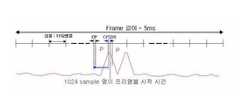
도 2에 도시된 바와 같이, 전체 프레임은 5 msec의 길이로 구성되어 있으며, 다운링크 프레임은 3.1104 msec, 업링크 프레임은 1.728 msec의 길이로 규정되어 있다. 또한, TTG는 121.2 μs, RTG는 40.4 μs의 길이로 규정되어 있다.As shown in Fig. 2, the entire frame is composed of 5 msec in length, the downlink frame is defined as 3.1104 msec and the uplink frame is 1.728 msec in length. In addition, TTG is defined as 121.2 μs and RTG is 40.4 μs in length.
전술한 와이브로 시스템의 프레임 구조에서 다운링크 신호와 업링크 신호를 구분하여 전송하기 위해서는, 중계기로 전송된 다운링크 신호와 업링크 신호에 대해 각각의 이동 경로를 제공할 수 있도록 다운링크 프레임과 업링크 프레임 사이에 존재하는 TTG와 RTG 구간에서 스위치가 전환되도록 스위칭 제어가 이루어져야 한다.In order to separately transmit the downlink signal and the uplink signal in the frame structure of the WiBro system described above, the downlink frame and the uplink may be provided to provide respective movement paths for the downlink signal and the uplink signal transmitted to the repeater. Switching control should be performed so that the switch is switched in the TTG and RTG intervals existing between the frames.
여기서, 다운링크 신호는 기지국에서 광중계기의 메인 도너(Donor)로 전달된 후에 광통신 케이블을 거쳐 광중계기의 리모트(Remote)로 전송되기 때문에 광통신 케이블의 시간 지연값을 고려해야 한다. 광통신 케이블에 의한 시간 지연은 대략 0 ~ 40 μs 정도이며, TTG 구간에서는 시간 지연을 고려한 스위칭 타이밍을 결정하여야 한다.Here, since the downlink signal is transmitted from the base station to the main donor of the optical repeater and then transmitted to the remote of the optical repeater through the optical communication cable, the time delay value of the optical communication cable should be considered. The time delay by the optical communication cable is about 0 to 40 μs, and the switching timing considering the time delay should be determined in the TTG section.
광통신 케이블에 의한 시간 지연을 고려하지 않고, TTG 구간의 앞부분이나 TTG 구간의 뒷부분을 스위칭 포인트로 결정하게 되면, 다운링크 신호 구간 또는 업링크 신호 구간과 스위칭 포인트가 겹치게 되어 부정확한 스위치 제어 신호에 의해 스위칭 동작이 수행될 수 있다. 따라서, 도 2에 도시된 바와 같이, 광통신 케이블의 시간 지연을 고려하여 TTG 구간의 시작점에서 55 μs 까지의 구간과 TTG 구간의 종료점부터 종료점 이전 55 μs 까지의 구간을 제외한 나머지 TTG 구간 사이에서 스위칭 포인트를 결정하도록 할 수 있다. 여기서, 55 μs의 시간 지연 보상 구간은 광통신 케이블에 의한 시간 지연을 보상하기 위한 적당한 길이를 선택한 것으로 이에 한정되지 않으며, 시간 지연값에 따라 길이의 조절이 가능하다.Without considering the time delay caused by the optical communication cable and determining the front part of the TTG section or the rear part of the TTG section as the switching point, the downlink signal section or the uplink signal section overlaps the switching point, resulting in an incorrect switch control signal. The switching operation can be performed. Accordingly, as shown in FIG. 2, the switching point between the TTG section except for the section up to 55 μs from the start point of the TTG section and the section up to 55 μs before the end point of the TTG section in consideration of the time delay of the optical communication cable. Can be determined. In this case, the 55 μs time delay compensation interval is an appropriate length for compensating for the time delay by the optical communication cable, and is not limited thereto. The length may be adjusted according to the time delay value.
한편, 전송 신호 프레임의 각 시간 구간은 전술한 시간 길이에 한정되는 것은 아니며, 필요에 따라 다운링크 프레임과 업링크 프레임의 시간 비율을 변경할 수도 있다. 이 경우, 변경된 시간 비율에 따라 TTG 구간과 RTG 구간의 위치를 결정하고, TTG 구간에서는 시간 지연 보상 구간을 제외한 나머지 구간에서 스위칭 포인트를 결정하면 된다.On the other hand, each time interval of the transmission signal frame is not limited to the above-described time length, it is also possible to change the time ratio of the downlink frame and uplink frame as necessary. In this case, the positions of the TTG section and the RTG section may be determined according to the changed time ratio, and the switching point may be determined in the remaining sections except for the time delay compensation section in the TTG section.
도 3은 본 발명의 바람직한 실시예에 따른 TDD 광중계기의 내부 구성을 나타낸 블록 구성도이다.Figure 3 is a block diagram showing the internal configuration of a TDD optical repeater according to a preferred embodiment of the present invention.
도 3에 도시된 바와 같이, 본 발명의 바람직한 실시예에 따른 TDD 광중계기는 메인 도너(300) 및 하나 이상의 리모트(350)를 포함할 수 있다.As shown in FIG. 3, a TDD optical repeater according to a preferred embodiment of the present invention may include a
TDD 광중계기의 메인 도너(300)는 RAS(110)와 RF 케이블을 통해 연결되어 있으며, RAS(110)로부터 RF 신호를 전송받으면 전광 변환을 거쳐 RF 신호를 광신호로 변환하고 광통신 케이블을 통해 리모트(350)에 광신호를 전송하며, 리모트(350)로부터 전송받은 광신호를 광전 변환을 거쳐 RF 신호로 변환하고 RF 케이블을 통해 RAS(110)에 전송한다.The
TDD 광중계기의 리모트(350)는 메인 도너(300)에서 광신호를 전송받으면 광전 변환을 거쳐 RF 신호로 변환하고 안테나를 통해 PSS(100)로 전송하며, PSS(100)로부터 전송받은 RF 신호를 전광 변환을 거쳐 광신호로 변환하고 광통신 케이블을 통해 메인 도너(300)에 전송한다.When the remote 350 of the TDD optical repeater receives an optical signal from the
메인 도너(300)는 내부 구성요소로서 LNA(Low Noise Amplifier)(305), 전광 변환 모듈(E/O)(310), WDM(Wavelength Division Multiplexer)(315), 광전 변환 모듈(O/E)(320) 및 HPA(High Power Amplifier)(325) 등을 포함할 수 있다. 또한, 리모트(350)는 내부 구성요소로서 WDM(355), 광전 변환 모듈(360), 커플러(Coupler)(365), HPA(370), 스위치(375), LNA(380), 전광 변환 모듈(385) 및 스위치 제어부(390) 등을 포함할 수 있다.The
여기서, 별도의 도면으로 도시하지는 않았으나 TDD 광중계기의 메인 도너(300)는 광통신 케이블을 통해 다수의 리모트(350)와 연결되어 광중계기의 커버리지를 확장할 수 있다. 이를 위해 메인 도너(300)는 다채널을 가지는 신호 분배기(미도시) 및 신호 결합기(미도시)를 포함할 수 있으며, RAS(110)로부터 전달받은 RF 신호를 신호 분배기를 통해 분기하여 LNA(305)로 전달하며 HPA(325)로부터 전달받 은 RF 신호를 신호 결합기를 통해 다른 리모트(350)의 출력과 합성하여 RF 케이블을 통해 RAS(110)로 전송할 수 있다. 또한, 본 발명의 이동 통신 시스템은 와이브로 시스템이므로 2.3 GHz 주파수 대역의 신호를 이용할 수 있다.Here, although not shown in a separate drawing, the
WDM(315, 355)은 광섬유 채널을 빛의 파장에 의해 다수의 채널로 분할하여 복수의 통신로로 사용할 수 있게 하는 장치로서, 광신호를 전송하는 경우에는 여러 광파장의 신호를 하나의 광섬유에 실어 전송하는 파장 분할 다중화기로서 동작하고, 광신호를 전송받는 경우에는 하나의 광섬유에 실린 여러 광파장의 신호를 각각 분기하는 파장 분할 역다중화기로서 동작할 수 있다. 전광 변환 모듈(310, 385)은 레이저 다이오드(Laser Diode)를 사용하여 구현할 수 있으며, 광전 변환 모듈(320, 360)은 포토 다이오드(Photo Diode)를 사용하여 구현할 수 있다.WDM (315, 355) is a device that divides an optical fiber channel into a plurality of channels by the wavelength of light and can be used as a plurality of communication channels. When transmitting optical signals, signals of several optical wavelengths are loaded on one optical fiber. When operating as a wavelength division multiplexer to transmit, and when receiving an optical signal, it can operate as a wavelength division demultiplexer for splitting the signals of several optical wavelengths carried in one optical fiber, respectively. The all-
스위치 제어부(390)는 커플러(365)에서 RF 신호를 감지하면, 다운링크 신호 및 업링크 신호를 구분하고 광통신 케이블에 의한 시간 지연을 보상한 스위치 제어 신호를 생성하여 스위치(375)로 전달한다.When the
도 2에서 전술한 대로 와이브로 시스템의 전송 신호 프레임 구조는 미리 정의되어 있으므로, 스위치 제어부(390)는 커플러(365)에서 감지한 전송 신호를 분석하여 전송 신호 프레임의 시작점을 검출하며, 검출된 시작점을 기준으로 전송 신호의 프레임 구조를 추정할 수 있다. 전송 신호의 프레임 구조를 추정하면 TTG와 RTG 시간 간격에서 스위칭 포인트를 결정하되, TTG 구간에서는 시간 지연 보상 구간을 제외한 나머지 구간에서 스위칭 포인트를 결정하도록 하여 시간 지연을 보상한 스위치 제어 신호를 생성하게 된다.Since the transmission signal frame structure of the WiBro system is previously defined in FIG. 2, the
전술한 TDD 광중계기의 구성요소를 이용하여 다운링크 방향 및 업링크 방향의 신호 전송 과정을 상세히 설명하면 아래와 같다.Hereinafter, a signal transmission process of the downlink direction and the uplink direction using the above-described components of the TDD optical repeater will be described in detail.
다운링크 방향의 경우, RAS(110)에서 RF 케이블을 통해 전송한 RF 신호는 메인 도너(300)의 LNA(305)에 전달된다. LNA(305)는 RF 신호의 잡음 성분을 줄이고 신호 성분을 증폭하여 전광 변환 모듈(310)로 전달하며, 전광 변환 모듈(310)은 전광 변환을 통해 RF 신호를 광신호로 변환하고 WDM(315)에 전달한다. WDM(315)은 전광 변환 모듈(310)로부터 전달받은 다수의 광신호를 광통신 케이블을 통해 리모트(350)에 전송한다.In the downlink direction, the RF signal transmitted by the
메인 도너(300)로부터 광신호를 전달받은 리모트(350)의 WDM(355)은 전달받은 다수의 광신호를 분기하여 광전 변환 모듈(360)로 전달하고, 광전 변환 모듈(360)은 광전 변환을 통해 광신호를 RF 신호로 변환하고 HPA(370)에 전달한다. HPA(370)는 RF 신호를 무선으로 송출하기 위한 실효 출력까지 증폭하여 스위치(375)로 전달하며, 스위치(375)에서는 안테나를 통해 RF 신호를 PSS(100)로 방사하게 된다.The
업링크 방향의 경우, 리모트(350)의 안테나를 통해 PSS(100)로부터 RF 신호를 전달받으면, LNA(380)를 거쳐 잡음을 제거하고 신호 성분을 증폭하여 전광 변환 모듈(385)에 전달한다. 전광 변환 모듈(385)은 전광 변환을 통해 RF 신호를 광신호로 변환하고 WDM(355)에 전달하며, WDM(355)은 전광 변환 모듈(385)로부터 전달받은 광신호를 광통신 케이블을 통해 메인 도너(300)에 전송한다.In the uplink direction, when the RF signal is received from the
리모트(350)로부터 광신호를 전달받은 메인 도너(300)의 WDM(315)은 전달받 은 다수의 광신호를 분기하여 광전 변환 모듈(320)로 전달하고, 광전 변환 모듈(320)은 광전 변환을 통해 광신호를 RF 신호로 변환하고 HPA(325)에 전달한다. HPA(325)는 RF 신호를 RAS(110)로 전송하기 위한 실효 출력까지 증폭하고 RF 케이블을 통해 RAS(110)에 전송한다.The
한편, 커플러(365)는 광전 변환 모듈(360)에서 HPA(370)로 전달되는 RF 신호를 감지하여 스위치 제어부(390)로 전달하며, 스위치 제어부(390)에서는 감지한 RF 신호를 분석하여 RF 신호의 전송을 위한 스위칭 제어 신호를 생성하여 스위치(375)로 전달한다. 스위치(375)는 전달받은 스위치 제어 신호의 제어에 의해, 스위치(375)에 다운링크 신호가 입력된 경우에는 안테나를 통해 PSS(100)로 방사하게 되며, 스위치(375)에 업링크 신호가 입력된 경우에는 HPA(370)와 연결되는 경로를 차단하고 업링크 신호가 LNA(380)로 입력되도록 경로를 설정한다.Meanwhile, the
도 4는 와이브로를 통하여 데이터를 전송하는 경우에 있어서 전송 신호 프레임의 프리앰블 시간 구조를 나타낸 도면이다.4 is a diagram illustrating a preamble time structure of a transmission signal frame in the case of transmitting data through WiBro.
OFDM/TDD 방식을 이용하는 와이브로 시스템에서 프레임을 구성하는 다운링크와 업링크는 다수 개의 OFDM 심볼(Symbol)로 구성될 수 있으며, OFDM 심볼은 데이터 심볼, 파일럿(Pilot) 심볼, 프리앰블 등을 포함할 수 있다. 여기서, 데이터 심볼은 데이터가 전송되는 시간 구간이고, 파일럿 심볼은 데이터 심볼 중간에 삽입되어 통신 채널이 다운링크인지 또는 업링크인지 추정하는 데 이용한다.In a WiBro system using an OFDM / TDD scheme, a downlink and an uplink constituting a frame may include a plurality of OFDM symbols, and the OFDM symbol may include a data symbol, a pilot symbol, and a preamble. have. Here, the data symbol is a time interval in which data is transmitted, and the pilot symbol is inserted in the middle of the data symbol and used to estimate whether the communication channel is downlink or uplink.
프리앰블은 데이터 전송이 시작되는 시점을 알려주어 전송 타이밍을 동기화하기 위해 사용된다. 전송 신호의 프레임의 다운링크 구간부터 시작되며 다운링크 구간은 프리앰블부터 시작되므로, 프리앰블을 이용하여 프레임의 시작 시점을 알 수 있다. 프리앰블은 짝수 주파수 오프셋 인덱스의 부반송파(Sub-Carrier) 집합으로 구성되므로, 프리앰블은 NFFT/2(NFFT = 1024) 샘플 패턴이 2회 반복되는 구조를 가진다. 여기서, NFFT는 FFT 변환으로 만들어 내는 샘플의 개수를 말한다. 또한, 다중 경로의 신호를 수집하고 부반송파 사이의 직교성을 유지하도록 하기 위해 CP 시간 구간이 프리앰블의 앞부분에 삽입된다.The preamble is used to indicate when data transmission begins and to synchronize transmission timing. Since the downlink period starts with the preamble and the downlink period of the frame of the transmission signal, the start time of the frame can be known using the preamble. Since the preamble consists of a sub-carrier set having an even frequency offset index, the preamble has a structure in which an NFFT / 2 (NFFT = 1024) sample pattern is repeated twice. Here, NFFT refers to the number of samples produced by the FFT transform. In addition, a CP time interval is inserted at the front of the preamble to collect signals of the multipath and to maintain orthogonality between subcarriers.
따라서, 도 4에 도시된 바와 같이, 프리앰블은 128 개의 샘플로 구성된 CP 시간 구간과 512 개의 샘플로 구성된 Pc 시간 구간이 2회 반복되는 유효 심볼 시간 구간으로 구성되어 전체 프리앰블은 1152 개의 샘플로 구성된다.Thus, as shown in FIG. 4, the preamble consists of a CP time interval of 128 samples and a valid symbol time interval of two repeated Pc time intervals of 512 samples, so that the entire preamble consists of 1152 samples. .
도 5는 와이브로를 통하여 데이터를 전송하는 경우에 있어서 전송 신호를 자기 상관 시킨 결과 출력된 신호 파형을 표시한 예시 화면이다.5 is an exemplary screen showing a signal waveform output as a result of autocorrelation of a transmission signal in the case of transmitting data through WiBro.
도 4에 대한 설명에서 전술한 대로 전송 신호 프레임은 프리앰블부터 시작되므로, 다운링크의 처음 두 개의 OFDM 심볼을 프리앰블로 구성하고 전송 신호를 일정 시간 지연시킨 후에 지연된 신호와 원 신호를 자기 상관(Auto-Correlation)시키면 도 5에 도시된 것과 같은 신호 파형이 출력되어, 전송 신호 프레임의 시작점을 검출할 수 있다.As described above with reference to FIG. 4, since the transmission signal frame starts with a preamble, the first two OFDM symbols of the downlink are configured as a preamble, and the delayed signal and the original signal are auto-correlated after delaying the transmission signal for a predetermined time. Correlation outputs a signal waveform as shown in FIG. 5 to detect the starting point of the transmission signal frame.
더욱 상세하게는, OFDM 방식을 이용하는 와이브로 시스템에서는 10 MHz의 샘플링(Sampling) 주파수를 가지므로 100 nsec의 샘플링 간격으로 전송 신호를 샘플링하게 된다. 따라서, RAS(110)와 PSS(100) 간의 전송 신호를 100 nsec의 샘플 단위로 샘플링하고 512 개의 샘플 시간 구간만큼 전송 신호를 지연시킨 후에 지연된 신호와 원 신호를 자기 상관시키면, 출력 파형은 한 개의 프레임에서 CP 시간 구간의 길이 동안 최대값을 유지하는 두 번의 최대점(Max Peak)을 가지게 된다.More specifically, since the WiBro system using the OFDM method has a sampling frequency of 10 MHz, the transmission signal is sampled at a sampling interval of 100 nsec. Therefore, when the transmission signal between the
두 번의 최대점은 각각 첫번째 프리앰블과 두번째 프리앰블에 의해 발생한 것이므로, 첫번째 최대점으로부터 1024 개의 샘플 시간 구간을 앞선 시점이 전송 신호 프레임의 시작점이 된다. 한편, 샘플링의 정확도를 향상시키기 위하여 샘플링 주파수를 높여 오버 샘플링(Over Sampling)을 하는 것도 가능하다.Since the two maximum points are generated by the first preamble and the second preamble, respectively, the time point that precedes 1024 sample time intervals from the first maximum point becomes the start point of the transmission signal frame. On the other hand, in order to improve sampling accuracy, the sampling frequency may be increased to oversample.
도 6은 본 발명의 바람직한 실시예에 따른 TDD 광중계기의 스위치 제어부의 내부 구성을 나타낸 블록 구성도이다.6 is a block diagram illustrating an internal configuration of a switch control unit of a TDD optical repeater according to an exemplary embodiment of the present invention.
도 6에 도시된 바와 같이, 본 발명의 바람직한 실시예에 따른 스위치 제어부(390)는 주파수 하향 변환기(Down Converter)(600), A/D 컨버터(610), 지연 모듈(Delay Module)(620), 자기 상관 모듈(Auto-Correlation Module)(630), 시작점 검출부(640) 및 제어 신호 생성부(650) 등을 포함할 수 있다.As shown in FIG. 6, the
주파수 하향 변환기(600)는 커플러(365)에서 전달받은 전송 신호의 주파수를 중간 대역 또는 기저 대역 주파수로 낮추어 A/D 컨버터(610)로 전달하며, A/D 컨버터(610)는 전달받은 전송 신호를 아날로그 신호에서 디지털 신호로 변환하여 지연 모듈(620)과 자기 상관 모듈(630)로 전달한다.The frequency down
지연 모듈(620)은 A/D 컨버터(610)로부터 전달받은 전송 신호를 일정 시간 지연시켜 자기 상관 모듈(630)로 전달한다. 자기 상관 모듈(630)은 A/D 컨버터(610)로부터 전달받은 전송 신호와 지연 모듈(620)로부터 전달받은 지연된 전송 신호를 자기 상관시켜 시작점 검출부(640)로 전달한다. 시작점 검출부(640)는 자기 상관 모듈(630)에서 출력된 자기 상관 결과값을 분석하여 전송 신호 프레임의 시작점을 검출한다. 여기서, 시작점 검출부(640)는 도 5에 대한 설명에서 서술한 방법으로 전송 신호 프레임의 시작점을 검출할 수 있다.The
제어 신호 생성부(650)는 시작점 검출부(640)로부터 전달받은 전송 신호 프레임의 시작점을 이용하여 전송 신호 프레임의 구조를 계산하고, 시간 지연을 보상한 스위치 제어 신호를 생성하여 스위치(375)로 전달한다. 전송 신호의 프레임의 길이와 다운링크 프레임, TTG, 업링크 프레임 및 RTG 시간 구간은 와이브로 규격에 미리 정의되어 있으므로, 제어 신호 생성부(650)는 전송 신호 프레임의 시작점을 기준으로 다운링크 프레임, TTG, 업링크 프레임 및 RTG 시간 구간을 계산할 수 있다. 전송 신호의 프레임 구조를 추정하면, TTG 시간 구간에서 시간 지연 보상 구간을 제외한 나머지 구간과 RTG 시간 구간에서 스위칭 포인트를 결정하여 스위칭 제어 신호를 생성하고 스위치(375)로 전달하게 된다.The
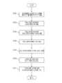
도 7은 본 발명의 바람직한 실시예에 따른 TDD 광중계기의 시간 지연 보상을 위한 스위칭 시간 결정 방법을 나타낸 순서도이다.7 is a flowchart illustrating a switching time determination method for time delay compensation of a TDD optical repeater according to a preferred embodiment of the present invention.
도 7에 도시된 바와 같이, RAS(110)로부터 다운링크 방향 전송 신호를 수신하면, TDD 광중계기의 메인 도너(300)에서 이를 전송받아 광신호로 변환한 후 광통신 케이블을 통해 리모트(350)로 전송한다(S700). 리모트(350)에서는 광신호를 다시 다운링크 방향 전송 신호로 변환하여 PSS(100)로 송출하게 되는데, 광전 변환 모듈(360)과 HPA(370) 사이에 위치한 커플러(365)에서 전송 신호를 감지하여 스위치 제어부(390)로 전달하게 된다(S702).As shown in FIG. 7, when the downlink direction transmission signal is received from the
스위치 제어부(390)에서는 전송 신호를 일정 시간 지연시킨 후에 지연된 신호와 원 신호를 자기 상관시킨 결과 파형을 분석하여 전송 신호 프레임의 시작점을 검출한다(S704). 도 6에 대한 설명에서 전술한 대로 전송 신호의 프레임 구조는 와이브로 규격에 미리 정의되어 있으므로, 스위치 제어부(390)는 전송 신호 프레임의 시작점을 기준으로 전송 신호 프레임을 구성하는 다운링크 프레임, TTG, 업링크 프레임 및 RTG 시간 구간을 계산하여 프레임 전체의 구조를 계산한다(S706).After delaying the transmission signal for a predetermined time, the
전송 신호의 프레임 구조를 계산하면, TTG 시간 구간에서 시간 지연 보상 구간을 제외한 나머지 구간과 RTG 시간 구간에서 스위칭 동작이 수행될 수 있도록 시간 지연을 보상한 스위칭 포인트를 결정한다(S708). 스위칭 포인트를 결정하면, 해당 포인트에서 스위칭 동작을 수행하도록 제어하는 스위치 제어 신호를 생성하여 스위치(375)로 전달한다(S710). 스위치(375)는 스위치 제어 신호에 의해 다운링크 신호와 업링크 신호를 구분하게 되며, 스위치(375)의 단락을 조절하여 각각의 신호에 대한 경로를 선택적으로 제공하게 된다(S712). 따라서, TDD 광중계기는 광통신 케이블에 의한 시간 지연이 발생하더라도, 이를 보상한 스위치 제어 신호에 의해 정확하게 다운링크 신호와 업링크 신호를 구분하여 전송 신호를 중계하게 된다.When the frame structure of the transmission signal is calculated, the switching point that compensates for the time delay is determined so that the switching operation can be performed in the remaining sections except the time delay compensation section in the TTG time section and the RTG time section (S708). When the switching point is determined, a switch control signal for controlling to perform a switching operation at the corresponding point is generated and transferred to the switch 375 (S710). The
이상의 설명은 본 발명을 예시적으로 설명한 것에 불과한 것으로, 본 발명이 속하는 기술분야에서 통상의 지식을 가지는 자라면 본 발명의 본질적인 특성에서 벗어나지 않는 범위에서 다양한 변형이 가능할 것이다. 따라서, 본 명세서에 개시된 실시예들은 본 발명을 한정하기 위한 것이 아니라 설명하기 위한 것이고, 이러한 실시예에 의하여 본 발명의 사상과 범위가 한정되는 것은 아니다. 본 발명의 범 위는 아래의 청구범위에 의하여 해석되어야 하며, 그와 동등한 범위 내에 있는 모든 기술은 본 발명의 권리범위에 포함되는 것으로 해석되어야 할 것이다.The above description is merely illustrative of the present invention, and those skilled in the art to which the present invention pertains may various modifications without departing from the essential characteristics of the present invention. Accordingly, the embodiments disclosed herein are not intended to limit the present invention but to describe the present invention, and the spirit and scope of the present invention are not limited by these embodiments. It is intended that the scope of the invention be interpreted by the following claims, and that all descriptions within the scope equivalent thereto will be construed as being included in the scope of the present invention.
이상에서 설명한 바와 같이 본 발명은, 와이브로 시스템의 TDD 광중계기 자체 내에서 다운링크 신호와 업링크 신호를 구분할 수 있는 스위치 제어 신호를 생성하여 스위칭 동작에 의해 각각의 신호에 대한 경로를 선택적으로 제공할 수 있는 효과가 있다.As described above, the present invention may generate a switch control signal capable of distinguishing a downlink signal and an uplink signal in the TDD optical repeater of the WiBro system to selectively provide a path for each signal by a switching operation. It can be effective.
또한, 광통신 케이블에 의한 시간 지연이 발생하더라도 시간 지연 보상을 적용한 스위치 제어 신호를 생성하여 정확한 스위칭 제어를 할 수 있기 때문에, TDD 광중계기에서 다운링크 신호와 업링크 신호를 효과적으로 중계할 수 있는 장점이 있다.In addition, since a switch control signal with time delay compensation can be generated and accurate switching control is performed even if a time delay occurs due to the optical communication cable, the TDD optical repeater effectively relays the downlink signal and the uplink signal. have.
Claims (27)
Translated fromKoreanPriority Applications (1)
| Application Number | Priority Date | Filing Date | Title |
|---|---|---|---|
| KR1020040085715AKR100590681B1 (en) | 2004-10-26 | 2004-10-26 | Switching Time Determination Method for Time Delay Compensation of TDD Optical Repeater in WiBro System and TDD Optical Repeater |
Applications Claiming Priority (1)
| Application Number | Priority Date | Filing Date | Title |
|---|---|---|---|
| KR1020040085715AKR100590681B1 (en) | 2004-10-26 | 2004-10-26 | Switching Time Determination Method for Time Delay Compensation of TDD Optical Repeater in WiBro System and TDD Optical Repeater |
Publications (2)
| Publication Number | Publication Date |
|---|---|
| KR20060036656A KR20060036656A (en) | 2006-05-02 |
| KR100590681B1true KR100590681B1 (en) | 2006-06-19 |
Family
ID=37144766
Family Applications (1)
| Application Number | Title | Priority Date | Filing Date |
|---|---|---|---|
| KR1020040085715AExpired - Fee RelatedKR100590681B1 (en) | 2004-10-26 | 2004-10-26 | Switching Time Determination Method for Time Delay Compensation of TDD Optical Repeater in WiBro System and TDD Optical Repeater |
Country Status (1)
| Country | Link |
|---|---|
| KR (1) | KR100590681B1 (en) |
Cited By (2)
| Publication number | Priority date | Publication date | Assignee | Title |
|---|---|---|---|---|
| KR100628330B1 (en) | 2004-11-02 | 2006-09-27 | 한국전자통신연구원 | Optical transponder having switching function |
| KR101542551B1 (en) | 2014-06-20 | 2015-08-07 | (주)티엘씨테크놀로지 | An apparatus for controlling delay of remote optical unit for wireless communication and the method thereof |
Families Citing this family (12)
| Publication number | Priority date | Publication date | Assignee | Title |
|---|---|---|---|---|
| KR100762637B1 (en) | 2006-05-03 | 2007-10-01 | 삼성전자주식회사 | Single Wavelength Bidirectional ROP Link Device for TD System Wireless Signal Transmission |
| KR100770883B1 (en)* | 2006-11-14 | 2007-10-26 | 삼성전자주식회사 | TDD Radio Over Fiber system and transmission time control method |
| KR100847394B1 (en)* | 2006-12-20 | 2008-07-18 | 엘지노텔 주식회사 | How to measure and compensate for time delay between RAS and JRH in portable data communication system |
| KR100856196B1 (en)* | 2007-01-03 | 2008-09-03 | 삼성전자주식회사 | Remote control method and system in TD type optical repeater |
| KR100866217B1 (en)* | 2007-03-28 | 2008-10-30 | 삼성전자주식회사 | Method and apparatus for configuring system delay time and frame length in time division duplexing system |
| KR101450875B1 (en)* | 2007-11-15 | 2014-10-24 | 삼성전자주식회사 | The decision method of tdd control in fiber relaying wireless communication system |
| KR101745669B1 (en) | 2016-01-15 | 2017-06-09 | 에스케이텔레시스 주식회사 | TDD Switching Control Apparatus for Use with Distributed Antenna System |
| KR101954227B1 (en) | 2017-04-28 | 2019-05-17 | 주식회사 케이티 | Wireless relay apparatus and method of operating thereof |
| US10686583B2 (en)* | 2017-07-04 | 2020-06-16 | Kandou Labs, S.A. | Method for measuring and correcting multi-wire skew |
| KR20210049461A (en) | 2019-10-25 | 2021-05-06 | 에스케이텔레콤 주식회사 | Apparatus for time synchronization of relay device and method therefor |
| KR102398348B1 (en) | 2020-08-20 | 2022-05-16 | 주식회사 셀콤 | Distributed Antenna System |
| KR102398351B1 (en) | 2020-09-08 | 2022-05-16 | 주식회사 셀콤 | Radio Unit |
- 2004
- 2004-10-26KRKR1020040085715Apatent/KR100590681B1/ennot_activeExpired - Fee Related
Cited By (2)
| Publication number | Priority date | Publication date | Assignee | Title |
|---|---|---|---|---|
| KR100628330B1 (en) | 2004-11-02 | 2006-09-27 | 한국전자통신연구원 | Optical transponder having switching function |
| KR101542551B1 (en) | 2014-06-20 | 2015-08-07 | (주)티엘씨테크놀로지 | An apparatus for controlling delay of remote optical unit for wireless communication and the method thereof |
Also Published As
| Publication number | Publication date |
|---|---|
| KR20060036656A (en) | 2006-05-02 |
Similar Documents
| Publication | Publication Date | Title |
|---|---|---|
| KR100590486B1 (en) | Method and system for generating switching timing signal for separating transmission signal in optical repeater of mobile communication network using TD and OPM modulation method | |
| KR100819257B1 (en) | RAIDIO OFIER system and method for controlling the transmission time | |
| CN1985449B (en) | Method and system for generating a switching timing signal for separating a transmit signal and a receive signal in an RF repeater of a mobile telecommunication network using TDD and OFDM modulation | |
| KR100842534B1 (en) | Method and system for generating switch control signal for separating transmission signal in TD type optical repeater | |
| KR100590681B1 (en) | Switching Time Determination Method for Time Delay Compensation of TDD Optical Repeater in WiBro System and TDD Optical Repeater | |
| KR100856196B1 (en) | Remote control method and system in TD type optical repeater | |
| KR101048960B1 (en) | Signal Transition Delay Time Compensation Switching Timing Generation Method for Optical Repeater and Optical Repeater for Signal Delay Compensation Between Base Station and Repeater in OBD-TD WiBro System | |
| KR20060031895A (en) | Switching Control Method of TD Repeater Using GPS Signal in Portable Internet System and Switch Control Apparatus therefor | |
| KR100770883B1 (en) | TDD Radio Over Fiber system and transmission time control method | |
| KR101035535B1 (en) | Digital time delay controller for controlling time delay of optical repeater in WiBro system and optical repeater using the same | |
| KR20060036657A (en) | Switching Time Determination Method for Time Delay Compensation of TDF Repeated RF Repeater in WiBro System and RF Repeater therefor | |
| KR101450875B1 (en) | The decision method of tdd control in fiber relaying wireless communication system | |
| KR20060031894A (en) | How to control a TV repeater in a portable Internet system and a TV repeater | |
| KR20080097795A (en) | Variable Time Delay Apparatus and Method Supporting Multi-hop Topology in Time Division Duplex Optical Repeater | |
| KR101049727B1 (en) | Base station of portable internet system with digital delay | |
| KR100695199B1 (en) | Method and system for providing mobile Internet service to AT moving at high speed using optical repeater | |
| KR20060038686A (en) | Method for generating switching timing signal of RF repeater and RF repeater for signal propagation delay time compensation between base station and repeater in OBD-TD WiBro system | |
| KR101087682B1 (en) | RF type delay device and method in mobile communication system using optical repeater | |
| HK1119848A (en) | Basestation methods and apparatus for supporting timing synchronization | |
| HK1119847A (en) | Methods and apparatus for supporting uplinks with remote base stations |
Legal Events
| Date | Code | Title | Description |
|---|---|---|---|
| A201 | Request for examination | ||
| PA0109 | Patent application | St.27 status event code:A-0-1-A10-A12-nap-PA0109 | |
| PA0201 | Request for examination | St.27 status event code:A-1-2-D10-D11-exm-PA0201 | |
| R18-X000 | Changes to party contact information recorded | St.27 status event code:A-3-3-R10-R18-oth-X000 | |
| PG1501 | Laying open of application | St.27 status event code:A-1-1-Q10-Q12-nap-PG1501 | |
| E701 | Decision to grant or registration of patent right | ||
| PE0701 | Decision of registration | St.27 status event code:A-1-2-D10-D22-exm-PE0701 | |
| GRNT | Written decision to grant | ||
| PR0701 | Registration of establishment | St.27 status event code:A-2-4-F10-F11-exm-PR0701 | |
| PR1002 | Payment of registration fee | St.27 status event code:A-2-2-U10-U11-oth-PR1002 Fee payment year number:1 | |
| PG1601 | Publication of registration | St.27 status event code:A-4-4-Q10-Q13-nap-PG1601 | |
| PR1001 | Payment of annual fee | St.27 status event code:A-4-4-U10-U11-oth-PR1001 Fee payment year number:4 | |
| PR1001 | Payment of annual fee | St.27 status event code:A-4-4-U10-U11-oth-PR1001 Fee payment year number:5 | |
| PR1001 | Payment of annual fee | St.27 status event code:A-4-4-U10-U11-oth-PR1001 Fee payment year number:6 | |
| PR1001 | Payment of annual fee | St.27 status event code:A-4-4-U10-U11-oth-PR1001 Fee payment year number:7 | |
| PN2301 | Change of applicant | St.27 status event code:A-5-5-R10-R13-asn-PN2301 St.27 status event code:A-5-5-R10-R11-asn-PN2301 | |
| L13-X000 | Limitation or reissue of ip right requested | St.27 status event code:A-2-3-L10-L13-lim-X000 | |
| U15-X000 | Partial renewal or maintenance fee paid modifying the ip right scope | St.27 status event code:A-4-4-U10-U15-oth-X000 | |
| FPAY | Annual fee payment | Payment date:20130403 Year of fee payment:8 | |
| PR1001 | Payment of annual fee | St.27 status event code:A-4-4-U10-U11-oth-PR1001 Fee payment year number:8 | |
| R18-X000 | Changes to party contact information recorded | St.27 status event code:A-5-5-R10-R18-oth-X000 | |
| FPAY | Annual fee payment | Payment date:20140610 Year of fee payment:9 | |
| PR1001 | Payment of annual fee | St.27 status event code:A-4-4-U10-U11-oth-PR1001 Fee payment year number:9 | |
| FPAY | Annual fee payment | Payment date:20150608 Year of fee payment:10 | |
| PR1001 | Payment of annual fee | St.27 status event code:A-4-4-U10-U11-oth-PR1001 Fee payment year number:10 | |
| LAPS | Lapse due to unpaid annual fee | ||
| PC1903 | Unpaid annual fee | St.27 status event code:A-4-4-U10-U13-oth-PC1903 Not in force date:20160610 Payment event data comment text:Termination Category : DEFAULT_OF_REGISTRATION_FEE | |
| PC1903 | Unpaid annual fee | St.27 status event code:N-4-6-H10-H13-oth-PC1903 Ip right cessation event data comment text:Termination Category : DEFAULT_OF_REGISTRATION_FEE Not in force date:20160610 | |
| P22-X000 | Classification modified | St.27 status event code:A-4-4-P10-P22-nap-X000 |