KR100588401B1 - Method for manufacturing optical fiber or optical element doped with reduced metal ions and / or rare earth ions - Google Patents
Method for manufacturing optical fiber or optical element doped with reduced metal ions and / or rare earth ionsDownload PDFInfo
- Publication number
- KR100588401B1 KR100588401B1KR1020030076539AKR20030076539AKR100588401B1KR 100588401 B1KR100588401 B1KR 100588401B1KR 1020030076539 AKR1020030076539 AKR 1020030076539AKR 20030076539 AKR20030076539 AKR 20030076539AKR 100588401 B1KR100588401 B1KR 100588401B1
- Authority
- KR
- South Korea
- Prior art keywords
- rare earth
- ions
- optical fiber
- sio
- doped
- Prior art date
- Legal status (The legal status is an assumption and is not a legal conclusion. Google has not performed a legal analysis and makes no representation as to the accuracy of the status listed.)
- Expired - Lifetime
Links
Images


Classifications
- C—CHEMISTRY; METALLURGY
- C03—GLASS; MINERAL OR SLAG WOOL
- C03B—MANUFACTURE, SHAPING, OR SUPPLEMENTARY PROCESSES
- C03B37/00—Manufacture or treatment of flakes, fibres, or filaments from softened glass, minerals, or slags
- C03B37/01—Manufacture of glass fibres or filaments
- C03B37/011—Manufacture of glass fibres or filaments starting from a liquid phase reaction process, e.g. through a gel phase
- H—ELECTRICITY
- H01—ELECTRIC ELEMENTS
- H01S—DEVICES USING THE PROCESS OF LIGHT AMPLIFICATION BY STIMULATED EMISSION OF RADIATION [LASER] TO AMPLIFY OR GENERATE LIGHT; DEVICES USING STIMULATED EMISSION OF ELECTROMAGNETIC RADIATION IN WAVE RANGES OTHER THAN OPTICAL
- H01S3/00—Lasers, i.e. devices using stimulated emission of electromagnetic radiation in the infrared, visible or ultraviolet wave range
- H01S3/05—Construction or shape of optical resonators; Accommodation of active medium therein; Shape of active medium
- H01S3/06—Construction or shape of active medium
- H01S3/063—Waveguide lasers, i.e. whereby the dimensions of the waveguide are of the order of the light wavelength
- H01S3/067—Fibre lasers
- H01S3/06708—Constructional details of the fibre, e.g. compositions, cross-section, shape or tapering
- H01S3/06716—Fibre compositions or doping with active elements
- H—ELECTRICITY
- H01—ELECTRIC ELEMENTS
- H01S—DEVICES USING THE PROCESS OF LIGHT AMPLIFICATION BY STIMULATED EMISSION OF RADIATION [LASER] TO AMPLIFY OR GENERATE LIGHT; DEVICES USING STIMULATED EMISSION OF ELECTROMAGNETIC RADIATION IN WAVE RANGES OTHER THAN OPTICAL
- H01S3/00—Lasers, i.e. devices using stimulated emission of electromagnetic radiation in the infrared, visible or ultraviolet wave range
- H01S3/14—Lasers, i.e. devices using stimulated emission of electromagnetic radiation in the infrared, visible or ultraviolet wave range characterised by the material used as the active medium
- H01S3/16—Solid materials
- H01S3/1601—Solid materials characterised by an active (lasing) ion
- H01S3/1603—Solid materials characterised by an active (lasing) ion rare earth
- C—CHEMISTRY; METALLURGY
- C03—GLASS; MINERAL OR SLAG WOOL
- C03B—MANUFACTURE, SHAPING, OR SUPPLEMENTARY PROCESSES
- C03B2201/00—Type of glass produced
- C03B2201/06—Doped silica-based glasses
- C03B2201/30—Doped silica-based glasses doped with metals, e.g. Ga, Sn, Sb, Pb or Bi
- C03B2201/34—Doped silica-based glasses doped with metals, e.g. Ga, Sn, Sb, Pb or Bi doped with rare earth metals, i.e. with Sc, Y or lanthanides, e.g. for laser-amplifiers
Landscapes
- Physics & Mathematics (AREA)
- Engineering & Computer Science (AREA)
- Electromagnetism (AREA)
- Chemical & Material Sciences (AREA)
- Plasma & Fusion (AREA)
- Optics & Photonics (AREA)
- Life Sciences & Earth Sciences (AREA)
- Dispersion Chemistry (AREA)
- Chemical Kinetics & Catalysis (AREA)
- General Life Sciences & Earth Sciences (AREA)
- Geochemistry & Mineralogy (AREA)
- Manufacturing & Machinery (AREA)
- Materials Engineering (AREA)
- Organic Chemistry (AREA)
- Optical Fibers, Optical Fiber Cores, And Optical Fiber Bundles (AREA)
- Glass Compositions (AREA)
Abstract
Translated fromKoreanDescription
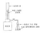
Translated fromKorean도 1은 본 발명의 공정이 수행되는 장치의 개요도이다.1 is a schematic diagram of an apparatus in which the process of the present invention is carried out.
도 2는 본 발명의 실시예1에 의해 제조된 환원된 희토류 이온(Tm2+)이 도핑된 광섬유의 광흡수 스펙트럼을 나타내는 그래프이다.2 is a graph showing the light absorption spectrum of the reduced rare earth ions (Tm2+ ) doped optical fiber prepared by Example 1 of the present invention.
도 3은 환원제를 사용하지 않은 비교예1에 의해 제조된 광섬유의 광흡수 스펙트럼을 나타내는 그래프이다.3 is a graph showing the light absorption spectrum of the optical fiber manufactured by Comparative Example 1 without using a reducing agent.
도 4는 본 발명의 실시예2 의해 제조된 환원된 희토류 이온(Eu2+)이 도핑된 광섬유의 광흡수 스펙트럼을 나타내는 그래프이다.Figure 4 is a graph showing the light absorption spectrum of the reduced rare earth ions (Eu2+ ) doped optical fiber prepared by Example 2 of the present invention.
도 5은 환원제를 사용하지 않은 비교예2 의해 제조된 광섬유의 광흡수 스펙트럼을 나타내는 그래프이다.5 is a graph showing the light absorption spectrum of the optical fiber manufactured by Comparative Example 2 not using a reducing agent.
본 발명은, 광섬유 또는 광소자 제조기술에 관한 것으로서, 특히 환원된 금 속 및/또는 희토류 이온이 도핑된 광섬유 또는 광소자를 제조하는 방법에 관한 것이다.BACKGROUND OF THE INVENTION 1. Field of the Invention The present invention relates to optical fiber or optical device manufacturing technology, and more particularly to a method for manufacturing an optical fiber or optical device doped with reduced metal and / or rare earth ions.
금속 이온 및/또는 희토류 이온이 첨가된 광섬유는, 광증폭기나 광스위칭 소자 등과 같은 다양한 응용성을 갖기 때문에, 특수 광섬유로 분류된다. 그에 따라, 그에 대한 연구가 많이 이루어지고 있다.Optical fibers to which metal ions and / or rare earth ions are added are classified as special optical fibers because they have various applications such as optical amplifiers and optical switching elements. Accordingly, a lot of research on it.
그러한 연구 과제 중의 하나가 도핑된 금속 및 희토류 이온의 환원기술이다. 일반적으로 원자는 원자가에 따라 원자의 에너지 준위 분포가 변하므로 광흡수 및 광방출과 같은 분광학적 특성이 다르게 나타난다. 따라서, 원자가의 변화를 통해 좀 더 다양한 광흡수 및 광방출 특성을 얻을 수 있고 이를 이용한 다양한 광증폭 및 광스위칭 특성을 갖는 광섬유 및 광소자를 얻을 수 있다. 일 예로, 희토류 이온들의 경우 원자가가 '3+'일 때는 4f의 전자 껍질과 5d의 전자 껍질 사이의 전자 천이에 의한 광흡수 특성이 자외선 영역에서만 나타나지만, 원자가가 '2+'로 바뀌게 되면 가시광선 및 적외선 영역에서도 광흡수특성이 일어나게 된다. 이런 이유로, 도핑된 금속 및 희토류 이온이 원하는 원자가를 갖도록 하는 기술이 필요하게 된다. 한편, 원소 마다 주로 존재하는 원자가가 있고, 이를 다른 원자가로 만들기 위해서는 특별한 공정이 요구된다.One such challenge is the reduction of doped metals and rare earth ions. In general, since the atomic energy level distribution varies depending on the valence, spectroscopic characteristics such as light absorption and light emission are different. Therefore, more various light absorption and light emission characteristics may be obtained through the change of valence, and optical fibers and optical devices having various optical amplification and optical switching characteristics using the same may be obtained. For example, in the case of rare earth ions, when the valence is '3+', the light absorption characteristics due to the electron transition between the electron shell of 4f and the electron shell of 5d are shown only in the ultraviolet region, but when the valence is changed to '2+', visible light And light absorption characteristics occur in the infrared region. For this reason, there is a need for techniques to ensure that the doped metals and rare earth ions have the desired valences. On the other hand, there is a valence mainly present for each element, and a special process is required to make it a different valency.
예를 들어 희토류 이온들은 대개 원자가가 '3+' 인 경우가 많다. 이를 안정적으로 '2+', '1+' 또는'0'의 원자가로 만들기 위해서는 이온의 환원처리가 필요하다. 현재까지 제안된 환원처리 방법은 다음과 같은 것들이 있다.Rare earth ions, for example, often have a valence of 3+. In order to stably make the valence of '2+', '1+' or '0', reduction treatment of ions is required. The reduction treatment methods proposed to date are as follows.
우선, 원자가가 3+인 희토류 이온에 감마선을 조사하는 방법이다. 그 예로 서, Tm3+이온이 첨가된 CaF2결정에 감마선을 조사하여 Tm2+이온을 얻는 것이 보고되었다.First, gamma rays are irradiated to rare earth ions having a valence of 3+. As an example, it has been reported to obtain Tm2+ ions by irradiating gamma rays to CaF2 crystals containing Tm3+ ions.
그러나 이 방법은 감마선 광원 취급의 위험성이 있고, 그에 따른 비용이 많이 소요되는 문제점이 있다.However, this method has a risk of handling the gamma ray light source, and there is a problem in that the cost is high.
또 다른 제안된 방법은 에어로졸 형태의 원료를 이용하는 방법이다. 이 방법은, 개선된 화학 기상 증착(modified chemical vapor deposition, MCVD) 공정이 필수적이다. 즉, 이 방법은 연소시에 희토류 이온 및 유리를 형성하는 가루와 함께 탄소를 생성하는 에어로졸 형태의 원료를 이용하여 석영 유리관 내에 희토류 이온이 첨가된 유리층을 쌓는 MCVD 공정을 포함한다. 이어, 탄소와 OH기를 제거하는 공정, 유리 소결 과정, 유리관의 함몰 과정을 순차적으로 진행하여 광섬유 모재를 얻는다. 그 예로서는 SiO2-Al2O3의 성분을 갖는 유리 광섬유에 있어서 Eu3+와 Sm3+를 각각 Eu2+와 Sm2+로 환원한 것들이다.Another proposed method is to use raw materials in the form of aerosols. This method requires an improved chemical vapor deposition (MCVD) process. That is, the method includes an MCVD process in which a rare earth ion is added to a glass layer in which a rare earth ion is added into a quartz glass tube using a raw material in the form of an aerosol that generates carbon together with the rare earth ions and the powder forming the glass upon combustion. Subsequently, a process of removing carbon and OH groups, a glass sintering process, and a depression process of the glass tube are sequentially performed to obtain an optical fiber base material. Examples thereof include those in which Eu3+ and Sm3+ are reduced to Eu2+ and Sm2+ in a glass optical fiber having a SiO2 -Al2 O3 component.
이와 같이 에어로졸 형태의 원료를 이용한 방법은, 현재까지는 MCVD 공정을 통해서만 이루어지고 있으며, 에어로졸 형태의 원하는 희토류 이온 원료 및 추가적인 에어로졸 공급장치가 필요하다.As such, the method using the aerosol type raw material has been made only through the MCVD process until now, and the desired rare earth ion raw material in the aerosol type and an additional aerosol supply device are required.
그 밖에 유리의 용융 과정에서 H2와 Ar 등의 혼합가스를 주입하여 환원된 희토류 이온을 얻는 방법이 제안되었다. 이 예로서는, SiO2-Al2O3 또는 SiO2-B2O3의 성 분을 갖는 유리에 있어서 Sm3+를 Sm2+로 환원한 것이다.In addition, a method of obtaining reduced rare earth ions by injecting a mixed gas such as H2 and Ar during melting of glass has been proposed. In this example, Sm3+ is reduced to Sm2+ in a glass having a component of SiO2 -Al2 O3 or SiO2 -B2 O3 .
이 방법은, 광섬유 모재 제작 공정이 기존의 광섬유 모재 제작 공정들에 비해 번거롭고 아직 일반화되지 못하고 있다.In this method, the optical fiber base material fabrication process is cumbersome compared to the conventional optical fiber base material manufacturing processes and is not yet generalized.
본 발명은 상술한 기존의 방법들보다 안전하면서 용이하게, 종래의 광섬유 및/또는 광소자 제조공정들을 사용할 수 있는, 환원된 금속 이온 및/또는 희토류 이온이 첨가된 광섬유 또는 광소자를 제조하는 방법을 제공하는데 그 목적이 있다.
The present invention provides a method for manufacturing an optical fiber or optical device to which reduced metal ions and / or rare earth ions are added, which can be used safely and easily than conventional methods described above. The purpose is to provide.
본 발명은 위의 목적에 따라 광섬유 또는 광소자 제조용 기재에 부분소결된 미세구조를 형성하고, 이 미세구조를 금속 이온 및/또는 희토류 이온과 함께 환원제를 포함하는 도핑용액에 일정시간동안 유지시키는 함침 공정을 실시하여, 금속 이온 및/또는 희토류 이온을 환원제와 같이 미세구조에 도핑시켜, 환원제를 통해 환원된 금속 이온 및/또는 희토류 이온들을 얻는 것을 특징으로 한다.The present invention forms a partially sintered microstructure on a substrate for manufacturing an optical fiber or an optical device according to the above object, and impregnates the microstructure with a metal ion and / or a rare earth ion for a predetermined time in a doping solution containing a reducing agent. By carrying out the process, the metal ions and / or the rare earth ions are doped into the microstructure, such as a reducing agent, to obtain reduced metal ions and / or rare earth ions through the reducing agent.
본 발명의 환원된 금속 이온 및/또는 희토류 이온이 도핑된 광섬유 또는 광소자 제조방법은, 광섬유 또는 광소자 제조용 기재에 부분소결된 미세구조를 형성하는 단계; 미세구조를 환원제를 포함하는 금속 이온 및/또는 희토류 이온 도핑용액에 함침시키는 단계; 금속이온 및/또는 희토류 이온이 함침된 미세구조를 건조시 키는 단계; 및 건조된 미세구조가 소결되도록 가열하는 단계를 포함한다.An optical fiber or optical device manufacturing method doped with reduced metal ions and / or rare earth ions of the present invention comprises the steps of forming a microstructure partially sintered on a substrate for optical fiber or optical device manufacturing; Impregnating the microstructure in a metal ion and / or rare earth ion doping solution comprising a reducing agent; Drying the microstructures impregnated with metal ions and / or rare earth ions; And heating the dried microstructures to sinter.
환원제는 바람직하게는 탄화수소화합물류이다. 그 예로서, 글루코스(glucose), 수크로스(sucrose), 글리세린(glycerine), 전분(dextrin), 벤젠(benzene), 페놀(phenol), 헥산(hexane), 톨루엔(toluene), 스티렌(styrene), 나프탈린(naphthalene) 등이 있다.The reducing agent is preferably a hydrocarbon compound. For example, glucose, sucrose, glycerin, starch, dextrin, benzene, phenol, hexane, toluene, styrene, Naphthalene and the like.
또한, 환원제는 TEOS(tetraethyl orthosilicate), TMOS(tetramethyl orthosilicate), TEOC(tetraethyl orthocarbonate), TMOC(tetramethyl orthocarbonate)와 같은 알콕사이드(alkoxide)류를 들 수 있다.In addition, reducing agents include alkoxides such as tetraethyl orthosilicate (TEOS), tetramethyl orthosilicate (TMOS), tetraethyl orthocarbonate (TEOC), and tetramethyl orthocarbonate (TMOC).
도핑되는 금속 이온 및/또는 희토류 이온은, Ce, Pr, Nd, Pm, Sm, Eu, Gd, Tb, Dy, Ho, Er, Tm, Yb, Lu, Al, Sc, Ti, V, Cr, Mn, Fe, Co, Ni, Cu, Zn, Y, Zr, Nb, Mo, Tc, Ru, Rh, Pd, Ag, Cd, In, Sn, Hf, Ta, W, Re, Os, Ir, Pt, Au, Tl, Pb, Bi 및 이들의 혼합물로 이루어진 군으로부터 선택된 하나이상의 이온이다.Doped metal ions and / or rare earth ions are Ce, Pr, Nd, Pm, Sm, Eu, Gd, Tb, Dy, Ho, Er, Tm, Yb, Lu, Al, Sc, Ti, V, Cr, Mn , Fe, Co, Ni, Cu, Zn, Y, Zr, Nb, Mo, Tc, Ru, Rh, Pd, Ag, Cd, In, Sn, Hf, Ta, W, Re, Os, Ir, Pt, Au At least one ion selected from the group consisting of Tl, Pb, Bi and mixtures thereof.
광섬유 또는 광소자 제조용 기재는 규소산화물(SiO2), 또는 규소산화물에 게르마늄산화물(GeO2), 붕소산화물(B2O3), 인산화물(P2O5) 및 티타늄산화물(TiO2) 중에서 선택된 하나 이상이 포함된 산화물 계열을 기본 조성으로 한다.The substrate for optical fiber or optical device manufacturing is silicon oxide (SiO2 ), or silicon oxide of germanium oxide (GeO2 ), boron oxide (B2 O3 ), phosphate (P2 O5 ) and titanium oxide (TiO2 ) The basic composition is an oxide series containing at least one selected.
바람직하게는 광섬유 또는 광소자 제조용 기재가 실리카(SiO2), 게르마노실리케이트(SiO2-GeO2), 포스포로실리케이트(SiO2-P2O5), 포스포로게르마노실리케이트(SiO2-GeO2-P2O5), 보로실리케이트(SiO2-B2O3), 보로포스 포로실리케이트(SiO2-P2O5-B2O3), 보로게르마노실리케이트(SiO2-GeO2-B2O3), 티타노실리케이트(SiO2-TiO2), 포스포로티타노실리케이트(SiO2-TiO2-P2O5) 또는 보로티타노실리케이트(SiO2-TiO2-B2O3)를 기본 조성으로 한다.Preferably, a substrate for manufacturing an optical fiber or an optical device includes silica (SiO2 ), germanosilicate (SiO2 -GeO2 ), phosphorosilicate (SiO2 -P2 O5 ), phosphorogermanosilicate (SiO2 -GeO2 -P2 O5 ), borosilicate (SiO2 -B2 O3 ), borophosphosilicate (SiO2 -P2 O5 -B2 O3 ), borogermanosilicate (SiO2 -GeO2- B2 O3 ), titanosilicate (SiO2 -TiO2 ), phosphoro titanosilicate (SiO2 -TiO2 -P2 O5 ) or boro titanosilicate (SiO2 -TiO2 -B2 O3 ) We assume composition.
본 발명에서 광소자는, 평면형 광증폭기, 광통신용 레이저, 평면형 광스위칭 소자 등의 평면형 광소자를 포함한다.In the present invention, the optical device includes a planar optical device such as a planar optical amplifier, an optical communication laser, and a planar optical switching device.
본 발명의 방법은, 광섬유 또는 광소자 제조용 기재(base material)에 부분소결된 미세구조를 형성하는 단계와, 그 미세구조를 금속 이온 및/또는 희토류 이온과, 환원제인 탄화수소화합물 또는 알콕사이드를 포함하는 도핑용액에 담그고 1 내지 1.5 시간 동안 유지시키는 함침(soaking) 단계를 포함한다. 즉, 환원제를 금속 이온 및/또는 희토류 이온과 함께 광섬유 또는 광소자 제조용 기재의 미세구조에 도핑시키는 것이다. 도핑된 이 환원제에 의해 환원된 금속 이온 및/또는 희토류 이온들이 얻어진다.The method of the present invention comprises forming a microstructure partially sintered in a base material for manufacturing an optical fiber or an optical device, the microstructure comprising metal ions and / or rare earth ions, and a hydrocarbon compound or alkoxide as a reducing agent. Soaking step of soaking in doping solution and maintained for 1 to 1.5 hours. That is, the reducing agent is doped together with the metal ions and / or the rare earth ions to the microstructure of the substrate for optical fiber or optical device manufacturing. Metal ions and / or rare earth ions reduced by this doped reducing agent are obtained.
본 발명의 방법은 광섬유 또는 광소자에 희토류 및/또는 금속 이온을 첨가할 수 있는 용액첨가법을 변형한 것이다. 이 용액첨가법은, 개선된 화학기상증착법(MCVD), 기상 축방향 증착법(vapor-phase axial deposition, VAD), 외부 기상 증착법(outside vapor deposition, OVD) 등과 같이 기존에 널리 사용되는 광섬유 모재(반제품) 제조방법들 중 어느 것과도 함께 이용될 수 있는, 광섬유 코어 내에 희토류 이온이나 금속 이온을 도핑시키는 방법이다. 용액첨가법은 또한 화염 가수분해 증착법(flame hydrolysis deposition, FHD)을 통한 평판형 유리 광소자 제조 공정에서도, 용액 형태로 준비가 가능한 모든 희토류 이온 및/또는 금속 이온의 도핑 방법으로 사용되고 있다.The method of the present invention is a modification of the solution addition method which can add rare earth and / or metal ions to an optical fiber or an optical element. This solution addition method is widely used for optical fiber base materials (semi-finished products) such as improved chemical vapor deposition (MCVD), vapor-phase axial deposition (VAD), and external vapor deposition (OVD). A method of doping rare earth ions or metal ions in an optical fiber core, which can be used with any of the manufacturing methods. The solution addition method is also used as a doping method for all rare earth ions and / or metal ions that can be prepared in solution in a flat glass optical device manufacturing process through flame hydrolysis deposition (FHD).
일예로서, MCVD 공정을 통한 용액첨가법(J.E Townsend, et al. "solution doping technique for fabrication of rare-earth doped optical fibers", Electron. Lett., Vol. 23, p.p.329-331, 1987 참조)은 다음과 같다. 여기서는 환원된 희토류 이온을 얻기 위해 도핑용액으로서 희토류 염화물과 함께 강한 환원제인 수크로스가 녹아있는 수용액이 사용된다. 우선, 기존의 MCVD 공정을 이용하여 실리카 관 내부에 부분소결되어 공극이 많은 코어층을 형성한다(MacChesney et.al., "Optical fber fabrication and resulting product", U.S Patent, 1997 참조). 이어, 그 관 내부를 희토류 염화물과 함께 수크로스가 녹아 있는 수용액으로 채운다. 코어층의 공극으로 용액침투가 충분히 이루어지도록 1 내지 1.5 시간 정도 유지시킨 다음, 수용액을 배출시킨다. 그 결과 공극에는 도핑용액이 잔류하게 된다. MCVD 공정을 이용하여 헬륨과 같은 불활성 가스만을 흐르게 하면서 100 내지 250℃로 유지하여, 수용액이 도핑된 코어층을 건조시킨다. 이때, 에탄올이나 수분이 제거된다. 이어, 수소-산소 불꽃을 이용하여, 수크로스로부터 생성되는 탄소가 제거되고 코어층이 완전소결될 때까지, 코어층을 2000℃ 정도의 고온으로 가열한다(M.F. Yan, et al., "Sintering of optical wave-guide glasses", J. of Mater. Sci., p.p. 1371-1378, 1980 참조). 그후, 계속 불활성가스를 흘려주면서 수소-산소 불꽃을 이용하여 2200℃ 이상의 고온으로 가열하는 함몰 과정(J.B. MacChesney, et. al., "Optical fiber fabrication and resulting product", U.S. Patent, 1997 참조)을 거쳐서 광섬유 모재를 제작한다. 이 광섬유 모재는 인출을 통해 환원된 희토류 이온이 첨가된 광섬유로 제조된다.As an example, solution addition via an MCVD process (see JE Townsend, et al. "Solution doping technique for fabrication of rare-earth doped optical fibers", Electron. Lett., Vol. 23, pp 329-331, 1987) As follows. Here, an aqueous solution in which sucrose, a strong reducing agent, is dissolved together with rare earth chloride is used as a doping solution to obtain reduced rare earth ions. First, a conventional MCVD process is used to partially sinter the inside of a silica tube to form a highly porous core layer (see MacChesney et.al., "Optical fber fabrication and resulting product", U.S Patent, 1997). The tube is then filled with an aqueous solution of sucrose dissolved with rare earth chlorides. The solution is kept for 1 to 1.5 hours to sufficiently infiltrate the solution into the pores of the core layer, and then the aqueous solution is discharged. As a result, the doping solution remains in the voids. The MCVD process is used to maintain the inert gas such as helium while maintaining only 100 to 250 ° C. to dry the core layer doped with the aqueous solution. At this time, ethanol and water are removed. Subsequently, using a hydrogen-oxygen flame, the core layer is heated to a high temperature of about 2000 ° C. until carbon generated from sucrose is removed and the core layer is completely sintered (MF Yan, et al., “Sintering of optical wave-guide glasses ", J. of Mater. Sci., pp 1371-1378, 1980). Subsequently, through a depressurization process (see JB MacChesney, et. Al., "Optical fiber fabrication and resulting product", US Patent, 1997) using a hydrogen-oxygen flame while continuously flowing an inert gas. Fabrication of optical fiber base material The optical fiber base material is made of an optical fiber to which rare earth ions are reduced by drawing out.
도핑용액에 포함된 수크로스는 C, H, O의 성분으로 이루어진 물질이다. 상술한 건조 과정에서, 이들 성분 중에 상당 부분의 H와 O는 제거되고, 탄소(C)만 남겨지게 된다. 이 탄소(C)가 2000℃정도의 고온에서 잔류하는 산소(O2)와 결합하여 일산화탄소(CO)을 형성하므로써, 도핑된 희토류 이온을 환원한다. 이때, 일산화탄소를 형성하는 반응을 위해 가해지는 온도는 엘링함 다이어그램(Ellingham Diagram)을 이용하여 희토류 이온의 환원을 일으킬 수 있을 정도로 정해진다. 그와 동시에, 탄소가 최대한 희토류 이온의 환원에 참여할 수 있도록, 실리카 유리관 내에서 반응을 일으키지 않는 불활성가스만을 주입하여 강한 환원분위기를 조성한다. 또한, 바람직하게는 광섬유 모재 제작을 위한 함몰과정도 불활성 가스만을 흐르게 하므로써 최대한 환원 분위기가 조성될 수 있도록 한다.Sucrose in the doping solution is a substance consisting of C, H, O components. In the drying process described above, a significant portion of these components, H and O, are removed, leaving only carbon (C). The carbon (C) combines with oxygen (O2 ) remaining at a high temperature of about 2000 ° C. to form carbon monoxide (CO), thereby reducing the doped rare earth ions. At this time, the temperature applied for the reaction to form the carbon monoxide is set to the extent that can cause the reduction of rare earth ions using the Ellingham Diagram. At the same time, in order to allow carbon to participate in the reduction of rare earth ions as much as possible, only an inert gas which does not cause a reaction in the silica glass tube is injected to form a strong reducing atmosphere. In addition, preferably, the depression process for fabricating the optical fiber base material allows only the inert gas to flow so that the reducing atmosphere can be formed as much as possible.
이상에서 설명한 공정은 광소자에도 적용될 수 있다.The process described above can also be applied to optical devices.
이하, 실시예를 들어 본 발명을 상세히 설명하지만, 본 발명이 하기 실시예에 한정되는 것은 아니다.Hereinafter, although an Example is given and this invention is demonstrated in detail, this invention is not limited to the following Example.
실시예1Example 1
먼저, 쑬륨염(TmCl3·6H2O) 및 수크로스(C12H22O11)를 각각 0.04M과 2.17M의 농 도로 초순수(deionized water)에 용해시켜서, 희토류 이온인 Tm3+와 환원제인 수크로스를 포함하는 도핑용액을 제조하였다. 여기서, 환원제는 탄화수소화합물류와, 알콕사이드류가 사용될 수 있다.First, the cerium salt (TmCl3 · 6H2 O) and sucrose (C12 H22 O11 ) are dissolved in deionized water at concentrations of 0.04 M and 2.17 M, respectively, to form rare earth ions Tm3+ and a reducing agent. A doping solution containing phosphorous sucrose was prepared. Here, the reducing agent may be used hydrocarbon compounds and alkoxides.
도 1에 나타낸 바와 같이, MCVD 공정을 통해, 내경이 19mm이고 외경이 25mm인 실리카 유리관 내벽에, 광섬유 코어가 될 부분의 유리 기본 조성이 SiO2-GeO2가 되도록, 다공성 미세구조를 형성시켰다. 이 유리관에 상기 제조한 도핑 용액을 주입시키고, 1시간 동안 유지시킨 후, 배출시켰다. 그후, 다시 MCVD 장치를 이용하여 헬륨만을 흘려주면서 100 내지 250℃로 가열하여 코어층을 건조시켰다.As shown in FIG. 1, through the MCVD process, a porous microstructure was formed on the inner wall of the silica glass tube having an inner diameter of 19 mm and an outer diameter of 25 mm such that the glass base composition of the portion to be the optical fiber core was SiO2 -GeO2 . The dope solution prepared above was injected into this glass tube, held for 1 hour, and then discharged. Thereafter, the core layer was dried by heating to 100 to 250 ° C while flowing only helium using the MCVD apparatus.
이어, 상술한 2000℃ 정도의 완전 소결 및 함몰 과정을 각각 8회와 15회 반복하였다. 그 결과 Tm2+이온이 도핑된 광섬유 모재가 얻어졌다. 이 광섬유 모재는 인출을 통해 광섬유로 제조되었다. 여기서 소결은 1600 내지 2200℃에서도 같은 결과가 얻어졌다.Subsequently, the above-described complete sintering and depression processes of about 2000 ° C. were repeated 8 times and 15 times, respectively. As a result, an optical fiber base material doped with Tm2+ ions was obtained. This optical fiber base material was made into optical fiber through drawing. The same result was obtained here also at 1600-2200 degreeC of sintering.
이와 같이 환원제인 수크로스를 포함한 도핑용액으로 제조된 본 발명의 광섬유의 광흡수스펙트럼을 도 2에 나타내었다. 도 2의 광흡수스펙트럼에서 465nm, 680nm, 785nm, 1210nm, 1600nm에서 나타난 광흡수스펙트럼은 Tm3+ 이온에 의해 형성되는 것이며, 400nm에서 약 900nm까지 넓게 분포하는 광흡수스펙트럼은 Tm2+ 이온에 의해 형성된 것이다.Thus, the light absorption spectrum of the optical fiber of the present invention prepared with a doping solution containing sucrose as a reducing agent is shown in FIG. In the light absorption spectrum of FIG. 2, the light absorption spectrum shown at 465 nm, 680 nm, 785 nm, 1210 nm, and 1600 nm is formed by Tm3+ ions, and the light absorption spectrum widely distributed from 400 nm to about 900 nm is represented by Tm2+ ions. Formed.
비교예1Comparative Example 1
환원제인 수크로스를 포함하지 않고 쑬륨염(TmCl3·6H2O) 및 알루미늄염(AlCl3·6H2O)을 각각 0.04M과 0.19M의 농도로 에탄올에 용해시킨 도핑용액을 준비하였다.A doping solution was prepared in which chlorine salt (TmCl3 · 6H2 O) and aluminum salt (AlCl3 · 6H2 O) were dissolved in ethanol at a concentration of 0.04M and 0.19M, respectively, without including sucrose as a reducing agent.
실시예1과 같은 방법으로 실리카 유리관 내벽에 다공성 미세구조를 갖는 코어층을 형성하였다. 이어 유리관 내부로 도핑용액을 주입시키고, 1시간 동안 유지시킨 후, 배출시켰다. 이어, 헬륨, 산소 및 염소를 흘려주면서 코어층을 건조시켰다.In the same manner as in Example 1, a core layer having a porous microstructure was formed on the inner wall of the silica glass tube. Then, the doping solution was injected into the glass tube, held for 1 hour, and then discharged. Then, the core layer was dried while flowing helium, oxygen, and chlorine.
실시예1과 같은 2000℃의 소결 및 함몰 과정을 각각 3회와 7회 반복하였다. 그 결과 Tm3+이온이 도핑된 광섬유 모재가 얻어졌다. 이 광섬유 모재는 인출을 통해 광섬유로 제조되었다.The same sintering and depression processes at 2000 ° C. as in Example 1 were repeated three times and seven times, respectively. As a result, an optical fiber base material doped with Tm3+ ions was obtained. This optical fiber base material was made into optical fiber through drawing.
이와 같이 환원제인 수크로스를 포함하지 않는 도핑용액으로 제조된 광섬유의 광흡수스펙트럼을 도3에 나타내었다. 환원제를 사용한 실시예 1의 결과와는 달리 Tm3+ 이온에 의한 광흡수스펙트럼만을 보여주고 있다.The optical absorption spectrum of the optical fiber prepared from the doping solution containing no sucrose as a reducing agent is shown in FIG. 3. Unlike the results of Example 1 using a reducing agent, only the light absorption spectrum by Tm3+ ions is shown.
실시예2Example 2
유로퓸염(EuCl3·xH2O) 및 수크로스(C12H22O11)를 각각 0.097M과 0.518M의 농도로 초순수(deionized water)에 용해시켜서, 희토류 이온인 Eu3+와 환원제인 수크로 스를 포함하는 도핑용액을 제조하였다.Europium salt (EuCl3 · xH2 O) and sucrose (C12 H22 O11 ) were dissolved in deionized water at concentrations of 0.097M and 0.518M, respectively, and rare earth ions Eu3+ and reducing agent souk A doping solution containing a furnace was prepared.
나머지는 실시예과 동일한 방법을 수행하여, Eu2+이온이 도핑된 광섬유를 얻었다.The rest was carried out in the same manner as in Example, to obtain an optical fiber doped with Eu2+ ions.
이와 같이 환원제인 수크로스를 포함한 도핑용액으로 제조된 광섬유의 광흡수스펙트럼을 도 4에 나타내었다. 도 4의 광흡수스펙트럼에서 600nm와 1200nm 사이에 널게 분포하는 광흡수스펙트럼은 Eu3+이온에서는 볼 수 없고 Eu2+이온에 의해 형성된 것이다.The optical absorption spectrum of the optical fiber prepared from the doping solution containing sucrose as a reducing agent is shown in FIG. 4. In the light absorption spectrum of FIG. 4, the light absorption spectrum widely distributed between 600 nm and 1200 nm is not seen in Eu3+ ions and is formed by Eu2+ ions.
비교예2Comparative Example 2
환원제인 수크로스를 포함하지 않고 유로퓸염(EuCl3·xH2O) 및 알루미늄염(AlCl3·6H2O)을 각각 0.097M과 0.518M의 농도로 에탄올에 용해시킨 도핑용액을 준비하였다.A doping solution was prepared in which europium salt (EuCl3 · xH2 O) and aluminum salt (AlCl3 · 6H2 O) were dissolved in ethanol at concentrations of 0.097 M and 0.518 M, respectively, without including sucrose as a reducing agent.
나머지는 비교예1과 동일한 방법을 수행하여, Eu3+이온이 도핑된 광섬유를 얻었다.The rest was carried out in the same manner as in Comparative Example 1 to obtain an optical fiber doped with Eu3+ ions.
이와 같이 환원제인 수크로스를 포함하지 않는 도핑용액으로 제조된 광섬유의 광흡수스펙트럼을 도 5에 나타내었다. 환원제를 사용한 실시예 2의 결과와는 달리 Eu3+이온에 의한 광흡수스펙트럼만을 보여주고 있다.The optical absorption spectrum of the optical fiber prepared with the doping solution containing no sucrose as a reducing agent is shown in FIG. 5. Unlike the results of Example 2 using a reducing agent, only the light absorption spectrum by Eu3+ ions is shown.
위의 실시예1 및 실시예2에서는 환원제를 포함하는 도핑용액에 의해 Tm2+이온이 도핑된 광섬유 모재, Eu2+이온이 도핑된 광섬유 모재를 얻을 수 있다는 것을 예시하고 있지만, 환원제가 갖는 환원포텐셜의 정도에 따라서, 3가에서 2가, 1가로 되기도 하고 경우에 따라서 0가 까지 환원된다는 것을 확인하였다. 0가 까지 환원된 경우에는 금속미립자 또는 희토류원소가 도핑된 광섬유 모재 또는 광소자가 형성된다.Although Examples 1 and 2 above illustrate that an optical fiber base material doped with Tm2+ ions and an optical fiber base material doped with Eu2+ ions can be obtained by a doping solution containing a reducing agent. Depending on the degree of potential, it was confirmed that trivalent to divalent and monovalent may be reduced to zero. When reduced to zero, an optical fiber base material or an optical element doped with metal fine particles or rare earth elements is formed.
위의 결과로부터 알 수 있는 바와 같이, 본 발명은, 용이한 용액첨가법을 이용하여 원하는 원자가를 갖는, 환원된 금속 이온 및/또는 희토류 이온이 도핑된 광섬유 또는 광소자를 제조할 수 있다.As can be seen from the above results, the present invention can prepare an optical fiber or an optical element doped with reduced metal ions and / or rare earth ions having a desired valency using an easy solution addition method.
본 발명의 방법은, 기존에 많이 이용되는 개선된 화학기상증착법(MCVD), 기상 축방향 증착법(vapor-phase axial deposition, VAD), 외부 기상 증착법(outside vapor deposition, OVD) 등을 그대로 이용하면서, 용이한 용액첨가법을 통해 환원된 금속 이온 및/또는 희토류 이온이 도핑된 광섬유 또는 광소자를 제조할 수 있다.The method of the present invention, while using the conventional improved chemical vapor deposition (MCVD), vapor-phase axial deposition (VAD), outside vapor deposition (OVD), etc. as it is, Through an easy solution addition method, an optical fiber or an optical device doped with reduced metal ions and / or rare earth ions can be manufactured.
Claims (12)
Translated fromKoreanPriority Applications (1)
| Application Number | Priority Date | Filing Date | Title |
|---|---|---|---|
| KR1020030076539AKR100588401B1 (en) | 2003-10-30 | 2003-10-30 | Method for manufacturing optical fiber or optical element doped with reduced metal ions and / or rare earth ions |
Applications Claiming Priority (1)
| Application Number | Priority Date | Filing Date | Title |
|---|---|---|---|
| KR1020030076539AKR100588401B1 (en) | 2003-10-30 | 2003-10-30 | Method for manufacturing optical fiber or optical element doped with reduced metal ions and / or rare earth ions |
Publications (2)
| Publication Number | Publication Date |
|---|---|
| KR20050041391A KR20050041391A (en) | 2005-05-04 |
| KR100588401B1true KR100588401B1 (en) | 2006-06-09 |
Family
ID=37242876
Family Applications (1)
| Application Number | Title | Priority Date | Filing Date |
|---|---|---|---|
| KR1020030076539AExpired - LifetimeKR100588401B1 (en) | 2003-10-30 | 2003-10-30 | Method for manufacturing optical fiber or optical element doped with reduced metal ions and / or rare earth ions |
Country Status (1)
| Country | Link |
|---|---|
| KR (1) | KR100588401B1 (en) |
Families Citing this family (3)
| Publication number | Priority date | Publication date | Assignee | Title |
|---|---|---|---|---|
| KR101335406B1 (en)* | 2012-06-14 | 2013-12-12 | 광주과학기술원 | Apparatus for manufacturing optical fiber and method for manufacturing optical fiber the same |
| CN104345358B (en)* | 2013-07-26 | 2016-02-10 | 上海煦源生物科技有限公司 | Stripping-mounting method is utilized to make the method for metal micro-nano structure at fiber end face |
| CN109553295B (en)* | 2018-12-25 | 2021-09-10 | 江苏通鼎光棒有限公司 | Large-size low-loss optical fiber preform and manufacturing method thereof |
Citations (5)
| Publication number | Priority date | Publication date | Assignee | Title |
|---|---|---|---|---|
| US4217027A (en)* | 1974-02-22 | 1980-08-12 | Bell Telephone Laboratories, Incorporated | Optical fiber fabrication and resulting product |
| KR19980069112A (en)* | 1997-02-26 | 1998-10-26 | 김광호 | Method for manufacturing optical waveguide with rare earth ions |
| KR20020011469A (en)* | 2000-08-02 | 2002-02-09 | 김효근 | Process for the preparation of metal ion-doped optical device |
| US6587633B2 (en)* | 2000-03-30 | 2003-07-01 | Corning Oti, Inc. | Active optical fibre doped with rare earth elements |
| KR20030088599A (en)* | 2002-05-13 | 2003-11-20 | 엘지전선 주식회사 | Optical fiber for optical amplifier and production method of the same |
- 2003
- 2003-10-30KRKR1020030076539Apatent/KR100588401B1/ennot_activeExpired - Lifetime
Patent Citations (6)
| Publication number | Priority date | Publication date | Assignee | Title |
|---|---|---|---|---|
| US4217027A (en)* | 1974-02-22 | 1980-08-12 | Bell Telephone Laboratories, Incorporated | Optical fiber fabrication and resulting product |
| US4217027B1 (en)* | 1974-02-22 | 1986-07-15 | ||
| KR19980069112A (en)* | 1997-02-26 | 1998-10-26 | 김광호 | Method for manufacturing optical waveguide with rare earth ions |
| US6587633B2 (en)* | 2000-03-30 | 2003-07-01 | Corning Oti, Inc. | Active optical fibre doped with rare earth elements |
| KR20020011469A (en)* | 2000-08-02 | 2002-02-09 | 김효근 | Process for the preparation of metal ion-doped optical device |
| KR20030088599A (en)* | 2002-05-13 | 2003-11-20 | 엘지전선 주식회사 | Optical fiber for optical amplifier and production method of the same |
Also Published As
| Publication number | Publication date |
|---|---|
| KR20050041391A (en) | 2005-05-04 |
Similar Documents
| Publication | Publication Date | Title |
|---|---|---|
| AU652351B2 (en) | Quartz glass doped with rare earth element and production thereof | |
| US8418504B2 (en) | Method of fabricating optical fiber or optical device doped with reduced metal ion and/or rare earth ion | |
| CN1287979A (en) | Method for mfg. optical fiber/rare-earth adulterate prefabricating elements | |
| CA2910731C (en) | A process for fabrication of ytterbium doped optical fiber | |
| CN109502961B (en) | A kind of ytterbium-doped silica optical fiber with anti-photodarkening and preparation method thereof | |
| US20130205832A1 (en) | Method for producing doped quartz glass | |
| KR100588401B1 (en) | Method for manufacturing optical fiber or optical element doped with reduced metal ions and / or rare earth ions | |
| EP1504295A1 (en) | Optical fiber for optical amplifier and process for manufacturing thereof | |
| EP2108624B1 (en) | Rare-earth-doped optical fiber, optical fiber amplifier, and method of manufacturing a preform for such a fiber | |
| Saha et al. | Vapor phase doping process for fabrication of rare earth doped optical fibers: Current status and future opportunities | |
| EP1602630B1 (en) | Glass-body-producing method | |
| KR20050040233A (en) | Method for fabricating optical fiber or optical device doped with reduced metal ion and/or rare earth ion | |
| Unger et al. | Rare-earth-doped laser fiber fabrication using vapor deposition technique | |
| JP2005132708A (en) | Manufacturing method of optical fiber or optical element doped with reduced metal ions and / or rare earth ions, and manufacturing method of optical fiber or optical element doped with reduced metal particles and / or rare earth elements | |
| RU2357934C2 (en) | Selective alloying of material | |
| KR100341544B1 (en) | Process for the preparation of metal ion-doped optical device | |
| JP2900732B2 (en) | Manufacturing method of optical waveguide | |
| CN1972880A (en) | Method for doping material and doped material | |
| JPH03265537A (en) | Rare-earth element-doped glass and its production | |
| Luo et al. | Radiation Effect on Optical Properties of Bi-Related Materials Co-Doped Silica Optical Fibers | |
| Mat-Sharif et al. | Highly Tm doped silica optical preform by MCVD-Chelate vapor delivery (Soot-dopant stepwise technique) | |
| Ramírez Martínez | Development of highly efficient thulium-doped high power fibre lasers | |
| JPH0350130A (en) | Production of quartz-based doped glass | |
| Unger et al. | Rare-Earth-Doped Laser Fiber Fabrication Using Vapor Deposition Technique | |
| Lupi et al. | Erbium-and magnesium-codoped silica-based transparent glass ceramic core fiber made by FCVD and flash vaporization |
Legal Events
| Date | Code | Title | Description |
|---|---|---|---|
| A201 | Request for examination | ||
| PA0109 | Patent application | St.27 status event code:A-0-1-A10-A12-nap-PA0109 | |
| PA0201 | Request for examination | St.27 status event code:A-1-2-D10-D11-exm-PA0201 | |
| R18-X000 | Changes to party contact information recorded | St.27 status event code:A-3-3-R10-R18-oth-X000 | |
| PN2301 | Change of applicant | St.27 status event code:A-3-3-R10-R13-asn-PN2301 St.27 status event code:A-3-3-R10-R11-asn-PN2301 | |
| PG1501 | Laying open of application | St.27 status event code:A-1-1-Q10-Q12-nap-PG1501 | |
| D13-X000 | Search requested | St.27 status event code:A-1-2-D10-D13-srh-X000 | |
| D14-X000 | Search report completed | St.27 status event code:A-1-2-D10-D14-srh-X000 | |
| E902 | Notification of reason for refusal | ||
| PE0902 | Notice of grounds for rejection | St.27 status event code:A-1-2-D10-D21-exm-PE0902 | |
| P11-X000 | Amendment of application requested | St.27 status event code:A-2-2-P10-P11-nap-X000 | |
| P13-X000 | Application amended | St.27 status event code:A-2-2-P10-P13-nap-X000 | |
| E701 | Decision to grant or registration of patent right | ||
| PE0701 | Decision of registration | St.27 status event code:A-1-2-D10-D22-exm-PE0701 | |
| GRNT | Written decision to grant | ||
| PR0701 | Registration of establishment | St.27 status event code:A-2-4-F10-F11-exm-PR0701 | |
| PR1002 | Payment of registration fee | St.27 status event code:A-2-2-U10-U11-oth-PR1002 Fee payment year number:1 | |
| PG1601 | Publication of registration | St.27 status event code:A-4-4-Q10-Q13-nap-PG1601 | |
| LAPS | Lapse due to unpaid annual fee | ||
| PC1903 | Unpaid annual fee | St.27 status event code:A-4-4-U10-U13-oth-PC1903 Not in force date:20090603 Payment event data comment text:Termination Category : DEFAULT_OF_REGISTRATION_FEE | |
| K11-X000 | Ip right revival requested | St.27 status event code:A-6-4-K10-K11-oth-X000 | |
| PC1903 | Unpaid annual fee | St.27 status event code:N-4-6-H10-H13-oth-PC1903 Ip right cessation event data comment text:Termination Category : DEFAULT_OF_REGISTRATION_FEE Not in force date:20090603 | |
| PR0401 | Registration of restoration | St.27 status event code:A-6-4-K10-K13-oth-PR0401 | |
| R401 | Registration of restoration | ||
| PR1001 | Payment of annual fee | St.27 status event code:A-4-4-U10-U11-oth-PR1001 Fee payment year number:4 | |
| PN2301 | Change of applicant | St.27 status event code:A-5-5-R10-R13-asn-PN2301 St.27 status event code:A-5-5-R10-R11-asn-PN2301 | |
| PR1001 | Payment of annual fee | St.27 status event code:A-4-4-U10-U11-oth-PR1001 Fee payment year number:5 | |
| PR1001 | Payment of annual fee | St.27 status event code:A-4-4-U10-U11-oth-PR1001 Fee payment year number:6 | |
| PN2301 | Change of applicant | St.27 status event code:A-5-5-R10-R13-asn-PN2301 St.27 status event code:A-5-5-R10-R11-asn-PN2301 | |
| PR1001 | Payment of annual fee | St.27 status event code:A-4-4-U10-U11-oth-PR1001 Fee payment year number:7 | |
| FPAY | Annual fee payment | Payment date:20130521 Year of fee payment:8 | |
| PR1001 | Payment of annual fee | St.27 status event code:A-4-4-U10-U11-oth-PR1001 Fee payment year number:8 | |
| PN2301 | Change of applicant | St.27 status event code:A-5-5-R10-R13-asn-PN2301 St.27 status event code:A-5-5-R10-R11-asn-PN2301 | |
| FPAY | Annual fee payment | Payment date:20140319 Year of fee payment:9 | |
| PR1001 | Payment of annual fee | St.27 status event code:A-4-4-U10-U11-oth-PR1001 Fee payment year number:9 | |
| FPAY | Annual fee payment | Payment date:20150526 Year of fee payment:10 | |
| PR1001 | Payment of annual fee | St.27 status event code:A-4-4-U10-U11-oth-PR1001 Fee payment year number:10 | |
| FPAY | Annual fee payment | Payment date:20160602 Year of fee payment:11 | |
| PR1001 | Payment of annual fee | St.27 status event code:A-4-4-U10-U11-oth-PR1001 Fee payment year number:11 | |
| P22-X000 | Classification modified | St.27 status event code:A-4-4-P10-P22-nap-X000 | |
| PR1001 | Payment of annual fee | St.27 status event code:A-4-4-U10-U11-oth-PR1001 Fee payment year number:12 | |
| FPAY | Annual fee payment | Payment date:20180328 Year of fee payment:13 | |
| PR1001 | Payment of annual fee | St.27 status event code:A-4-4-U10-U11-oth-PR1001 Fee payment year number:13 | |
| P22-X000 | Classification modified | St.27 status event code:A-4-4-P10-P22-nap-X000 | |
| FPAY | Annual fee payment | Payment date:20190329 Year of fee payment:14 | |
| PR1001 | Payment of annual fee | St.27 status event code:A-4-4-U10-U11-oth-PR1001 Fee payment year number:14 | |
| PR1001 | Payment of annual fee | St.27 status event code:A-4-4-U10-U11-oth-PR1001 Fee payment year number:15 | |
| PR1001 | Payment of annual fee | St.27 status event code:A-4-4-U10-U11-oth-PR1001 Fee payment year number:16 | |
| PR1001 | Payment of annual fee | St.27 status event code:A-4-4-U10-U11-oth-PR1001 Fee payment year number:17 | |
| PR1001 | Payment of annual fee | St.27 status event code:A-4-4-U10-U11-oth-PR1001 Fee payment year number:18 | |
| PC1801 | Expiration of term | St.27 status event code:N-4-6-H10-H14-oth-PC1801 Not in force date:20231031 Ip right cessation event data comment text:Termination Category : EXPIRATION_OF_DURATION | |
| R18-X000 | Changes to party contact information recorded | St.27 status event code:A-5-5-R10-R18-oth-X000 | |
| R18-X000 | Changes to party contact information recorded | St.27 status event code:A-5-5-R10-R18-oth-X000 |