KR100587337B1 - Earphone Jacks and Connectors for Electronics - Google Patents
Earphone Jacks and Connectors for ElectronicsDownload PDFInfo
- Publication number
- KR100587337B1 KR100587337B1KR1020030088141AKR20030088141AKR100587337B1KR 100587337 B1KR100587337 B1KR 100587337B1KR 1020030088141 AKR1020030088141 AKR 1020030088141AKR 20030088141 AKR20030088141 AKR 20030088141AKR 100587337 B1KR100587337 B1KR 100587337B1
- Authority
- KR
- South Korea
- Prior art keywords
- connector
- earphone jack
- inner diameter
- jack
- protective cap
- Prior art date
- Legal status (The legal status is an assumption and is not a legal conclusion. Google has not performed a legal analysis and makes no representation as to the accuracy of the status listed.)
- Expired - Fee Related
Links
Images


Classifications
- H—ELECTRICITY
- H01—ELECTRIC ELEMENTS
- H01R—ELECTRICALLY-CONDUCTIVE CONNECTIONS; STRUCTURAL ASSOCIATIONS OF A PLURALITY OF MUTUALLY-INSULATED ELECTRICAL CONNECTING ELEMENTS; COUPLING DEVICES; CURRENT COLLECTORS
- H01R24/00—Two-part coupling devices, or either of their cooperating parts, characterised by their overall structure
- H01R24/58—Contacts spaced along longitudinal axis of engagement
- H—ELECTRICITY
- H04—ELECTRIC COMMUNICATION TECHNIQUE
- H04R—LOUDSPEAKERS, MICROPHONES, GRAMOPHONE PICK-UPS OR LIKE ACOUSTIC ELECTROMECHANICAL TRANSDUCERS; DEAF-AID SETS; PUBLIC ADDRESS SYSTEMS
- H04R1/00—Details of transducers, loudspeakers or microphones
- H04R1/10—Earpieces; Attachments therefor ; Earphones; Monophonic headphones
- H04R1/1041—Mechanical or electronic switches, or control elements
- H—ELECTRICITY
- H01—ELECTRIC ELEMENTS
- H01R—ELECTRICALLY-CONDUCTIVE CONNECTIONS; STRUCTURAL ASSOCIATIONS OF A PLURALITY OF MUTUALLY-INSULATED ELECTRICAL CONNECTING ELEMENTS; COUPLING DEVICES; CURRENT COLLECTORS
- H01R2107/00—Four or more poles
- H—ELECTRICITY
- H01—ELECTRIC ELEMENTS
- H01R—ELECTRICALLY-CONDUCTIVE CONNECTIONS; STRUCTURAL ASSOCIATIONS OF A PLURALITY OF MUTUALLY-INSULATED ELECTRICAL CONNECTING ELEMENTS; COUPLING DEVICES; CURRENT COLLECTORS
- H01R2201/00—Connectors or connections adapted for particular applications
- H01R2201/16—Connectors or connections adapted for particular applications for telephony
Landscapes
- Physics & Mathematics (AREA)
- Engineering & Computer Science (AREA)
- Acoustics & Sound (AREA)
- Signal Processing (AREA)
- Connector Housings Or Holding Contact Members (AREA)
Abstract
Translated fromKoreanDescription
Translated fromKorean도 1은 종래의 이어폰잭과 커넥터 및 보호캡이 구비된 이동통신단말기를 나타낸 사시도.1 is a perspective view showing a conventional earphone jack and a mobile communication terminal equipped with a connector and a protective cap.
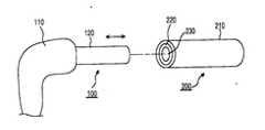
도 2는 본 발명에 따른 이어폰잭과 커넥터의 사시도.Figure 2 is a perspective view of the earphone jack and the connector according to the present invention.
도 3은 본 발명에 따른 이어폰잭과 커넥터의 분리상태를 나타내는 단면도.Figure 3 is a cross-sectional view showing a separation state of the earphone jack and the connector according to the present invention.
도 4는 본 발명에 따른 이어폰잭과 커넥터의 결합상태를 나타내는 단면도.Figure 4 is a cross-sectional view showing a coupling state of the earphone jack and the connector according to the present invention.
*** 도면의 주요부분에 대한 부호의 설명 ****** Explanation of symbols for main parts of drawing ***
100 : 이어폰잭 110 : 몸체 120 : 잭플러그100: earphone jack 110: body 120: jack plug
121 : 장입요홈부 130 : 결착부재 200 : 커넥터121: loading groove 130: binding member 200: connector
210 : 외관부 211 : 단턱부 212 : 입구210: exterior portion 211: step 212: entrance
220 : 돌기부 221 : 결착요홈부 230 : 보호캡220: protrusion 221: binding groove 230: protective cap
240 : 스프링240: spring
본 발명은 전자제품용 이어폰잭과 커넥터에 관한 것으로써, 특히 이물질의 유입을 방지하는 보호수단이 일체형으로 구비되는 커넥터와 상기 커넥터에 결합되는 이어폰잭을 구비하여 종래와 같이 이어폰잭과 커넥터의 결합 및 분리시 상기 커넥터로 이물질이 유입되는 것을 방지하는 보호캡을 커넥터로 부터 분리 및 결합하여야 하는 불편함을 사전에 방지할 수 있도록 하는 전자제품요 이어폰잭과 커넥터를 제공하는 것이다.The present invention relates to an earphone jack and a connector for an electronic product, in particular, a connector provided with an integrally provided with a protective means for preventing the inflow of foreign matter and an earphone jack coupled to the connector, the combination of the earphone jack and the connector as in the prior art And it is to provide an electronic product earphone jack and connector to prevent in advance the inconvenience that the separation and coupling from the connector to the protective cap to prevent foreign matters to be introduced into the connector during separation.
일반적으로 이동통신단말기, 카세트, 컴퓨터, 라디오 등과 같은 일종의 음향기기에는 이어폰잭을 접속하여 수신음을 청취할 수 있도록 커넥터가 구비되었다.In general, a kind of audio device such as a mobile communication terminal, a cassette, a computer, a radio, and the like is provided with a connector so as to listen to a reception sound by connecting an earphone jack.
그리고, 상기 커넥터에 이어폰잭을 접속하지 않은 상태에서는 이물질이 유입되지 않도록 별도의 보호캡을 구비하여 그 입구를 개폐하였다.In addition, when the earphone jack is not connected to the connector, the inlet and the inlet are provided with a separate protective cap to prevent foreign substances from entering.
도 1은 종래의 이어폰잭과 커넥터 및 보호캡이 구비된 이동통신단말기를 나타낸 사시도이다.1 is a perspective view showing a conventional earphone jack and a mobile communication terminal equipped with a connector and a protective cap.
도시한 바와같이 이동통신단말기(10)의 커넥터(20)에 이어폰잭을 결합시에는 커넥터(20)와 별도로 이동통신단말기에 구비된 보호캡(40)을 커넥터(20)의 접속구(21)에서 분리한 후에 커넥터(20)의 접속구(21)에 이어폰잭(30)의 플러그(31)를 삽착하였다.As shown in the drawing, when the earphone jack is coupled to the connector 20 of the
이후, 커넥터(20)의 접속구(21)에서 이어폰잭(30)의 플러그(31)를 빼낸 후에는 커넥터(20)의 접속구(21) 입구를 보호캡(40)으로 막아주므로써 이물직이 커넥터(20)의 접속구(21)로 유입되는 것을 방지할 수 있었다.Subsequently, after removing the plug 31 of the earphone jack 30 from the connector 21 of the connector 20, by blocking the entrance of the connector 21 of the connector 20 with the
따라서, 이어폰 사용자는 이어폰잭(30)과 커넥터(20)의 결합 및 분리에 따라 커넥터(20)에서 보호캡(40)을 분리 및 결합하여야 하는 불편함이 있었다. Therefore, the earphone user has a inconvenience in that the
이에 본 발명은 이와같은 문제점을 해결하기 위하여 안출한 것으로써, 특히 커넥터에 이어폰잭을 결합 및 분리시 별도로 보호캡을 개폐함이 커넥터에 이어폰잭을 결합 및 분리할 수 있도록 하는 전자제품용 이어폰잭과 커넥터를 제공하는 것을 목적으로 한다.Therefore, the present invention has been made in order to solve the above problems, in particular, when the earphone jack to the connector to separate and disconnect the earphone cap for the electronic product to connect and disconnect the earphone jack to the connector separately And to provide a connector.
이에 본 발명은 전자제품용 이어폰잭과 커넥터에 있어서,In the present invention, in the earphone jack and connector for electronic products,
소정의 길이로 형성되어 있는 돌기부와, 상기 돌기부가 내경 중심부에 길이방향으로 돌설되고 그 선단부에 입구가 형성되어 있는 외관부와, 상기 외관부의 내경과 돌기부의 외경 사이에 길이방향으로 이동되게 설치되며 외관부의 입구로 이물질이 유입되는 것을 방지하는 보호캡과, 상기 보호캡을 탄성적으로 지지하도록 외관부의 내경과 돌기부의 외경사이에 설치되는 스프링으로 구성되는 커넥터와;A protruding portion formed to a predetermined length, the protruding portion protruding in the longitudinal direction at the center of the inner diameter and having an inlet formed at the distal end thereof, and being moved in the longitudinal direction between the inner diameter of the outer portion and the outer diameter of the protruding portion; A connector comprising a protective cap for preventing foreign substances from entering the inlet of the exterior portion, and a spring installed between the inner diameter of the exterior portion and the outer diameter of the protrusion portion to elastically support the protective cap;
사용자가 탈착시 잡을 수 있도록 형성되어 있은 몸체와, 상기 몸체의 일면부에 돌설되며 외관부의 내경부에 삽입되고 돌기부가 삽입되도록 선단에 길이방향으로 장입요홈부가 형성되어 있은 잭플러그로 구성되는 이어폰잭으로 이루어지는 것을 특징으로 하는 전자제품용 이어폰잭과 커넥터를 제공한다. The earphone jack is composed of a body which is formed to be gripped by the user, and a jack plug which is protruded into one side of the body and is inserted into the inner diameter of the exterior part and has a recess in the longitudinal direction at the tip so that the protrusion is inserted. It provides an earphone jack and connector for an electronic product, characterized in that consisting of.
본 발명의 구성 및 올바른 실시예를 첨부되는 도 2, 3, 4를 참조하여 자세하게 설명하면 다음과 같다.If described in detail with reference to Figures 2, 3, 4 of the configuration and the correct embodiment of the present invention are as follows.
도 2는 본 발명에 따른 이어폰잭과 커넥터의 사시도이고, 도 3은 본 발명에 따른 이어폰잭과 커넥터의 분리상태를 나타내는 단면도이고, 도 4는 본 발명에 따 른 이어폰잭과 커넥터의 결합상태를 나타내는 단면도이다. Figure 2 is a perspective view of the earphone jack and the connector according to the invention, Figure 3 is a cross-sectional view showing a separation state of the earphone jack and the connector according to the invention, Figure 4 is a coupling state of the earphone jack and the connector according to the present invention It is sectional drawing to show.
본 발명에 따른 이어폰잭과 커넥터의 구성을 도 2, 3, 4를 참조하여 자세하게 설명하면 다음과 같다.The configuration of the earphone jack and the connector according to the present invention will be described in detail with reference to FIGS. 2, 3, and 4 as follows.
본 발명에 따른 이어폰잭(100)과 커낵터는 일반적인 전자제품에 사용되는 것이다.The
먼저, 본 발명에 따른 커넥터(200)는 소정의 길이로 형성되어 있는 돌기부(220)와, 상기 돌기부(220)가 내경 중심부에 길이방향으로 돌설되고 그 선단부에 입구(212)가 형성되어 있는 외관부(210)와, 상기 외관부(210)의 내경과 돌기부(220)의 외경 사이에 길이방향으로 이동되게 설치되여 외관부(210)의 입구(212)로 이물질이 유입되는 것을 방지하는 보호캡(230)과, 상기 보호캡(230)을 탄성적으로 지지하도록 외관부(210)의 내경과 돌기부(220)의 외경사이에 설치되는 스프링(240)으로 구성된다.First, the
상기 외관부(210)의 입구(212) 내측에는 보호캡(230)의 이탈을 방지하는 단턱부(211)를 돌설한다.Inside the
상기 돌기부(220)의 그 선단이 외관부(210)의 입구(212) 밖으로 돌출되지 않도록 형성함이 바람직하다.It is preferable that the tip of the
상기 보호캡(230)은 외관부(210)의 내경으로 이물질이 유입되는 것을 방지함은 물론이고 길이방향으로 이동이 자유롭게 그 내경을 돌기부(220)의 외경과 그 외경은 외관부(210)의 내경과 밀접되도록 형성함이 바람직하다.The
또한, 본 발명에 따른 이어폰잭(100)은 사용자가 탈착시 잡을 수 있도록 형 성되어 있은 몸체(110)와, 상기 몸체(110)의 일면부에 돌설되며 외관부(210)의 내경부에 삽입되고 돌기부(220)가 내삽되도록 선단에 길이방향으로 장입요홈부(121)가 형성되어 있는 잭플러그(120)로 구성된다.In addition, the
그리고 상기 돌기부(220)는 선단부 소정부위에 외경을 따라 오목하게 결착요홈부(221)을 형성하고, 상기 장입요홈부(121)의 내측 소정부위에는 결착요홈부(221)에 삽입되어 돌기부(220)를 직경방향으로 탄성지지하는 결착부재(130)를 형성한다.And the
상기 결착부재(130)는 일단이 장입요홈부(121)의 소정부위에 고정되어 있고 타단은 직경방향으로 완충이동되는 자유단을 갖은 탄성재질로 형성한다. The
이와같이 구성되는 본 발명에 따른 이어폰잭(100)과 커넥터(200)의 올바른 작동 실시예를 첨부되는 도 3, 4를 참조하여 자세하게 설명하면 다음과 같다.Referring to Figures 3 and 4 attached to the correct operation of the
먼저, 이어폰잭(100)과 커넥터(200)의 결합상태를 알아보면 도 4에 도시한 바와같이 이어폰잭(100)의 잭플러그(120)가 커넥터(200)의 외관부(210)의 내경에 삽입된 상태를 말한다.First, as shown in FIG. 4, the
이를 자세히 설명하며 이어폰잭(100)의 몸체(110)를 잡고 그 선단의 잭플러그(120)를 커넥터(200)의 외관부(210)의 내경으로 삽입하면, 그와 동시에 잭플러그(120)의 장입요홈부(121)에 돌기부(220)가 삽입되고, 또한, 상기 스프링(240)에 지지되어 외관부(210)의 입구(212)를 막고 있던 보호캡(230)은 잭플러그(120)의 선단에 밀려서 외관부(210)의 내부 하측에 위치하게되고, 그 상태에서 잭플러그(120)의 장입요홈부(121) 내면과 돌기부(220)의 외면 사이의 표면마찰력에 의하여 이어폰잭(100)과 커넥터(200)는 자체적으로 분리되지 않게된다.This will be described in detail and holding the
이때, 상기 돌기부(220)의 선단부에 형성한 결착요홈부(221)에는 결착부재(130)가 삽입되어 자유단이 돌기부(220)에 직경방향으로 일정한 탄성압력을 가하게되여 이어폰잭(100)과 커넥터(200)의 결속력이 강화된다.At this time, the
이후, 몸체(110)를 잡고 길이방향으로 잡아당기므로써, 잭플러그(120)를 커넥터(200)의 외관부(210)의 내경에서 빼내여 이어폰잭(100)과 커넥터(200)를 분리한다.Then, by holding the
이때, 보호캡(230)은 스프링(240)의 탄성복원력에 의하여 외관부(210)의 입구(212)쪽으로 이동된 후, 단턱부(211)에 걸려서 정지하게되며, 그 위치에서 보호캡(230)은 이물질이 외관부(210)의 내부로 유입되지 않도록 외관부(210)의 입구(212)를 막아준다.At this time, the
이상에서 살펴본 바와같이 본 발명 따른 이어폰잭과 커넥터는 통상의 전자제품에 사용되는 것으로써, 이어폰잭과 커넥터의 결합 및 분리에 따라 일체형으로 구비된 보호캡이 길이방향으로 이동되여 커넥터의 입구가 개폐되도록 하여 종래와같이 커넥터의 입구를 개폐하는 보호캡을 별도로 구비하고 또한, 상기 보호캡을 수동으로 개폐하여야 하는 단점을 미연에 방지할 수 있는 효과가 있다.As described above, the earphone jack and the connector according to the present invention are used in a general electronic product, and a protective cap integrally provided in accordance with the coupling and separation of the earphone jack and the connector is moved in the longitudinal direction to open and close the inlet of the connector. In order to provide a separate protective cap to open and close the inlet of the connector as in the prior art, there is an effect that can be prevented in advance to the disadvantage of having to manually open and close the protective cap.
Claims (5)
Translated fromKoreanPriority Applications (2)
| Application Number | Priority Date | Filing Date | Title |
|---|---|---|---|
| KR1020030088141AKR100587337B1 (en) | 2003-12-05 | 2003-12-05 | Earphone Jacks and Connectors for Electronics |
| CNB2004100571729ACN100334782C (en) | 2003-12-05 | 2004-08-27 | Headset jack and connector for electronic productor |
Applications Claiming Priority (1)
| Application Number | Priority Date | Filing Date | Title |
|---|---|---|---|
| KR1020030088141AKR100587337B1 (en) | 2003-12-05 | 2003-12-05 | Earphone Jacks and Connectors for Electronics |
Publications (2)
| Publication Number | Publication Date |
|---|---|
| KR20050055187A KR20050055187A (en) | 2005-06-13 |
| KR100587337B1true KR100587337B1 (en) | 2006-06-08 |
Family
ID=34793149
Family Applications (1)
| Application Number | Title | Priority Date | Filing Date |
|---|---|---|---|
| KR1020030088141AExpired - Fee RelatedKR100587337B1 (en) | 2003-12-05 | 2003-12-05 | Earphone Jacks and Connectors for Electronics |
Country Status (2)
| Country | Link |
|---|---|
| KR (1) | KR100587337B1 (en) |
| CN (1) | CN100334782C (en) |
Families Citing this family (2)
| Publication number | Priority date | Publication date | Assignee | Title |
|---|---|---|---|---|
| EP2640170B1 (en)* | 2007-01-06 | 2015-07-29 | Apple Inc. | Wireless headset comprising a housing and an earbud electrically coupled to the housing by a flexible circuit board |
| CN111129819B (en)* | 2019-12-13 | 2021-10-15 | 中航光电科技股份有限公司 | A seven-core AUX interface connector |
Citations (6)
| Publication number | Priority date | Publication date | Assignee | Title |
|---|---|---|---|---|
| KR900010737U (en)* | 1988-11-11 | 1990-06-04 | 가부시끼 가이샤 비쯔바 덴끼 세이사꾸쇼 | Coil device |
| KR930008368Y1 (en)* | 1991-08-27 | 1993-12-22 | 삼성전자 주식회사 | Cover for jack terminal |
| KR200146254Y1 (en)* | 1995-10-26 | 1999-06-15 | 윤종용 | Tuner Jack Breakage Prevention Device |
| JPH11297399A (en)* | 1998-04-09 | 1999-10-29 | Shinwa Denki:Kk | Circular plug |
| JP2000215945A (en)* | 1999-01-21 | 2000-08-04 | Funai Electric Co Ltd | Connector plug structure |
| KR200221932Y1 (en)* | 2000-11-17 | 2001-04-16 | 하나테크주식회사 | JACK for Power Connector |
Family Cites Families (6)
| Publication number | Priority date | Publication date | Assignee | Title |
|---|---|---|---|---|
| DE8910843U1 (en)* | 1989-09-11 | 1991-01-17 | Siemens AG, 1000 Berlin und 8000 München | Snap lock for coaxial connectors |
| FR2670294B1 (en)* | 1990-12-06 | 1993-03-19 | Merlin Gerin | TEST TAKE. |
| CN2355448Y (en)* | 1998-12-29 | 1999-12-22 | 富士康(昆山)电脑接插件有限公司 | Electric connector |
| JP2001093609A (en)* | 1999-09-24 | 2001-04-06 | Ryosei Electro-Circuit Systems Ltd | Connector |
| JP2001319727A (en)* | 2000-05-12 | 2001-11-16 | Kenwood Corp | Jack dustproof structure |
| CN2458771Y (en)* | 2000-12-07 | 2001-11-07 | 鸿松精密工业股份有限公司 | Connector module |
- 2003
- 2003-12-05KRKR1020030088141Apatent/KR100587337B1/ennot_activeExpired - Fee Related
- 2004
- 2004-08-27CNCNB2004100571729Apatent/CN100334782C/ennot_activeExpired - Fee Related
Patent Citations (6)
| Publication number | Priority date | Publication date | Assignee | Title |
|---|---|---|---|---|
| KR900010737U (en)* | 1988-11-11 | 1990-06-04 | 가부시끼 가이샤 비쯔바 덴끼 세이사꾸쇼 | Coil device |
| KR930008368Y1 (en)* | 1991-08-27 | 1993-12-22 | 삼성전자 주식회사 | Cover for jack terminal |
| KR200146254Y1 (en)* | 1995-10-26 | 1999-06-15 | 윤종용 | Tuner Jack Breakage Prevention Device |
| JPH11297399A (en)* | 1998-04-09 | 1999-10-29 | Shinwa Denki:Kk | Circular plug |
| JP2000215945A (en)* | 1999-01-21 | 2000-08-04 | Funai Electric Co Ltd | Connector plug structure |
| KR200221932Y1 (en)* | 2000-11-17 | 2001-04-16 | 하나테크주식회사 | JACK for Power Connector |
Also Published As
| Publication number | Publication date |
|---|---|
| CN1624988A (en) | 2005-06-08 |
| KR20050055187A (en) | 2005-06-13 |
| CN100334782C (en) | 2007-08-29 |
Similar Documents
| Publication | Publication Date | Title |
|---|---|---|
| US7500882B2 (en) | Releasable connector system | |
| US20150333458A1 (en) | Releasable plug connector system | |
| US6733323B2 (en) | Pull tab for extracting electrical connector | |
| JP2002141140A (en) | Connector link auxiliary structure of cellular phone | |
| KR100587337B1 (en) | Earphone Jacks and Connectors for Electronics | |
| KR100791760B1 (en) | External connection terminal switchgear of electronic equipment | |
| KR100566511B1 (en) | Electrical connector | |
| CN114786086A (en) | Earphone charging box, earphone and earphone assembly | |
| US20070059980A1 (en) | Keyed cable assembly to restrain cable under multiaxis stress | |
| JPH11273780A (en) | Mounting structure of connector protective cover | |
| KR100802617B1 (en) | Connecting device and portable terminal having same | |
| CN218849956U (en) | HDMI high definition data line | |
| JP3347032B2 (en) | Plug-out prevention structure for sound listening device | |
| KR100617803B1 (en) | Interface connector cover of wireless terminal | |
| CN220421980U (en) | Earphone plug structure | |
| KR20200103960A (en) | Data connecting gender and case for potable electric apparatus and connecting structure with each other | |
| KR20060093873A (en) | In-out connector device for preventing foreign substances from entering the mobile communication terminal | |
| CN219498375U (en) | Connector socket and connector | |
| CN222073375U (en) | Electronic equipment and earphone | |
| KR200351676Y1 (en) | A connection apparatus of the portable telephone | |
| KR200211458Y1 (en) | Head set connection structure of Mobile station | |
| CN211126321U (en) | Protection device for wire connector of mobile unit | |
| KR200277453Y1 (en) | Holding structure for portable audio device | |
| KR20060040445A (en) | Jack connection structure of electronic device | |
| KR200399222Y1 (en) | Ear-Phone for Mobile Communication Device |
Legal Events
| Date | Code | Title | Description |
|---|---|---|---|
| A201 | Request for examination | ||
| PA0109 | Patent application | St.27 status event code:A-0-1-A10-A12-nap-PA0109 | |
| PA0201 | Request for examination | St.27 status event code:A-1-2-D10-D11-exm-PA0201 | |
| PG1501 | Laying open of application | St.27 status event code:A-1-1-Q10-Q12-nap-PG1501 | |
| D13-X000 | Search requested | St.27 status event code:A-1-2-D10-D13-srh-X000 | |
| D14-X000 | Search report completed | St.27 status event code:A-1-2-D10-D14-srh-X000 | |
| E902 | Notification of reason for refusal | ||
| PE0902 | Notice of grounds for rejection | St.27 status event code:A-1-2-D10-D21-exm-PE0902 | |
| T11-X000 | Administrative time limit extension requested | St.27 status event code:U-3-3-T10-T11-oth-X000 | |
| E13-X000 | Pre-grant limitation requested | St.27 status event code:A-2-3-E10-E13-lim-X000 | |
| P11-X000 | Amendment of application requested | St.27 status event code:A-2-2-P10-P11-nap-X000 | |
| P13-X000 | Application amended | St.27 status event code:A-2-2-P10-P13-nap-X000 | |
| R17-X000 | Change to representative recorded | St.27 status event code:A-3-3-R10-R17-oth-X000 | |
| E701 | Decision to grant or registration of patent right | ||
| PE0701 | Decision of registration | St.27 status event code:A-1-2-D10-D22-exm-PE0701 | |
| GRNT | Written decision to grant | ||
| PR0701 | Registration of establishment | St.27 status event code:A-2-4-F10-F11-exm-PR0701 | |
| PR1002 | Payment of registration fee | St.27 status event code:A-2-2-U10-U11-oth-PR1002 Fee payment year number:1 | |
| PG1601 | Publication of registration | St.27 status event code:A-4-4-Q10-Q13-nap-PG1601 | |
| PN2301 | Change of applicant | St.27 status event code:A-5-5-R10-R13-asn-PN2301 St.27 status event code:A-5-5-R10-R11-asn-PN2301 | |
| PR1001 | Payment of annual fee | St.27 status event code:A-4-4-U10-U11-oth-PR1001 Fee payment year number:4 | |
| R18-X000 | Changes to party contact information recorded | St.27 status event code:A-5-5-R10-R18-oth-X000 | |
| R18-X000 | Changes to party contact information recorded | St.27 status event code:A-5-5-R10-R18-oth-X000 | |
| PR1001 | Payment of annual fee | St.27 status event code:A-4-4-U10-U11-oth-PR1001 Fee payment year number:5 | |
| PR1001 | Payment of annual fee | St.27 status event code:A-4-4-U10-U11-oth-PR1001 Fee payment year number:6 | |
| PR1001 | Payment of annual fee | St.27 status event code:A-4-4-U10-U11-oth-PR1001 Fee payment year number:7 | |
| FPAY | Annual fee payment | Payment date:20130424 Year of fee payment:8 | |
| PR1001 | Payment of annual fee | St.27 status event code:A-4-4-U10-U11-oth-PR1001 Fee payment year number:8 | |
| FPAY | Annual fee payment | Payment date:20140424 Year of fee payment:9 | |
| PR1001 | Payment of annual fee | St.27 status event code:A-4-4-U10-U11-oth-PR1001 Fee payment year number:9 | |
| FPAY | Annual fee payment | Payment date:20150424 Year of fee payment:10 | |
| PR1001 | Payment of annual fee | St.27 status event code:A-4-4-U10-U11-oth-PR1001 Fee payment year number:10 | |
| PN2301 | Change of applicant | St.27 status event code:A-5-5-R10-R13-asn-PN2301 St.27 status event code:A-5-5-R10-R11-asn-PN2301 | |
| FPAY | Annual fee payment | Payment date:20160422 Year of fee payment:11 | |
| PR1001 | Payment of annual fee | St.27 status event code:A-4-4-U10-U11-oth-PR1001 Fee payment year number:11 | |
| P22-X000 | Classification modified | St.27 status event code:A-4-4-P10-P22-nap-X000 | |
| LAPS | Lapse due to unpaid annual fee | ||
| PC1903 | Unpaid annual fee | St.27 status event code:A-4-4-U10-U13-oth-PC1903 Not in force date:20170531 Payment event data comment text:Termination Category : DEFAULT_OF_REGISTRATION_FEE | |
| PC1903 | Unpaid annual fee | St.27 status event code:N-4-6-H10-H13-oth-PC1903 Ip right cessation event data comment text:Termination Category : DEFAULT_OF_REGISTRATION_FEE Not in force date:20170531 | |
| PN2301 | Change of applicant | St.27 status event code:A-5-5-R10-R13-asn-PN2301 St.27 status event code:A-5-5-R10-R11-asn-PN2301 |