KR100586639B1 - Gas nozzle in plasma process chamber - Google Patents
Gas nozzle in plasma process chamberDownload PDFInfo
- Publication number
- KR100586639B1 KR100586639B1KR1020050097151AKR20050097151AKR100586639B1KR 100586639 B1KR100586639 B1KR 100586639B1KR 1020050097151 AKR1020050097151 AKR 1020050097151AKR 20050097151 AKR20050097151 AKR 20050097151AKR 100586639 B1KR100586639 B1KR 100586639B1
- Authority
- KR
- South Korea
- Prior art keywords
- gas nozzle
- gas
- inner tube
- rod
- process chamber
- Prior art date
- Legal status (The legal status is an assumption and is not a legal conclusion. Google has not performed a legal analysis and makes no representation as to the accuracy of the status listed.)
- Expired - Fee Related
Links
Images


Classifications
- C—CHEMISTRY; METALLURGY
- C23—COATING METALLIC MATERIAL; COATING MATERIAL WITH METALLIC MATERIAL; CHEMICAL SURFACE TREATMENT; DIFFUSION TREATMENT OF METALLIC MATERIAL; COATING BY VACUUM EVAPORATION, BY SPUTTERING, BY ION IMPLANTATION OR BY CHEMICAL VAPOUR DEPOSITION, IN GENERAL; INHIBITING CORROSION OF METALLIC MATERIAL OR INCRUSTATION IN GENERAL
- C23C—COATING METALLIC MATERIAL; COATING MATERIAL WITH METALLIC MATERIAL; SURFACE TREATMENT OF METALLIC MATERIAL BY DIFFUSION INTO THE SURFACE, BY CHEMICAL CONVERSION OR SUBSTITUTION; COATING BY VACUUM EVAPORATION, BY SPUTTERING, BY ION IMPLANTATION OR BY CHEMICAL VAPOUR DEPOSITION, IN GENERAL
- C23C16/00—Chemical coating by decomposition of gaseous compounds, without leaving reaction products of surface material in the coating, i.e. chemical vapour deposition [CVD] processes
- C23C16/44—Chemical coating by decomposition of gaseous compounds, without leaving reaction products of surface material in the coating, i.e. chemical vapour deposition [CVD] processes characterised by the method of coating
- C23C16/455—Chemical coating by decomposition of gaseous compounds, without leaving reaction products of surface material in the coating, i.e. chemical vapour deposition [CVD] processes characterised by the method of coating characterised by the method used for introducing gases into reaction chamber or for modifying gas flows in reaction chamber
- C23C16/45563—Gas nozzles
- C23C16/45578—Elongated nozzles, tubes with holes
- C—CHEMISTRY; METALLURGY
- C23—COATING METALLIC MATERIAL; COATING MATERIAL WITH METALLIC MATERIAL; CHEMICAL SURFACE TREATMENT; DIFFUSION TREATMENT OF METALLIC MATERIAL; COATING BY VACUUM EVAPORATION, BY SPUTTERING, BY ION IMPLANTATION OR BY CHEMICAL VAPOUR DEPOSITION, IN GENERAL; INHIBITING CORROSION OF METALLIC MATERIAL OR INCRUSTATION IN GENERAL
- C23C—COATING METALLIC MATERIAL; COATING MATERIAL WITH METALLIC MATERIAL; SURFACE TREATMENT OF METALLIC MATERIAL BY DIFFUSION INTO THE SURFACE, BY CHEMICAL CONVERSION OR SUBSTITUTION; COATING BY VACUUM EVAPORATION, BY SPUTTERING, BY ION IMPLANTATION OR BY CHEMICAL VAPOUR DEPOSITION, IN GENERAL
- C23C16/00—Chemical coating by decomposition of gaseous compounds, without leaving reaction products of surface material in the coating, i.e. chemical vapour deposition [CVD] processes
- C23C16/44—Chemical coating by decomposition of gaseous compounds, without leaving reaction products of surface material in the coating, i.e. chemical vapour deposition [CVD] processes characterised by the method of coating
- C23C16/50—Chemical coating by decomposition of gaseous compounds, without leaving reaction products of surface material in the coating, i.e. chemical vapour deposition [CVD] processes characterised by the method of coating using electric discharges
- C23C16/513—Chemical coating by decomposition of gaseous compounds, without leaving reaction products of surface material in the coating, i.e. chemical vapour deposition [CVD] processes characterised by the method of coating using electric discharges using plasma jets
Landscapes
- Chemical & Material Sciences (AREA)
- Engineering & Computer Science (AREA)
- General Chemical & Material Sciences (AREA)
- Chemical Kinetics & Catalysis (AREA)
- Materials Engineering (AREA)
- Mechanical Engineering (AREA)
- Metallurgy (AREA)
- Organic Chemistry (AREA)
- Physics & Mathematics (AREA)
- Plasma & Fusion (AREA)
- Plasma Technology (AREA)
Abstract
Translated fromKoreanDescription
Translated fromKorean도 1a 및 도 1b는 본 발명과 관련된 플라즈마 프로세스 챔버의 수직 및 수평 단면도;1A and 1B are vertical and horizontal cross-sectional views of a plasma process chamber in accordance with the present invention;
도 2a 및 도 2b는 도 1a의 플라즈마 프로세스 챔버에 장착된 가스 노즐의 일 예를 보여주는 단면도 및 정면도;2A and 2B are cross-sectional and front views showing an example of a gas nozzle mounted to the plasma process chamber of FIG. 1A;
도 3a 내지 도 3d는 본 발명의 제1 실시예에 따른 가스 노즐의 사시도, 정면도 및 단면도;3A to 3D are perspective, front and sectional views of a gas nozzle according to the first embodiment of the present invention;
도 4a 및 도 4b는 도 3a의 가스 노즐의 변형예를 보여주는 사시도;4A and 4B are perspective views showing a modification of the gas nozzle of FIG. 3A;
도 5a 내지 도 5c는 본 발명의 제2 실시예에 따른 가스 노즐의 사시도, 정면도 및 단면도;5A-5C are perspective, front and sectional views of a gas nozzle according to a second embodiment of the present invention;
도 6a 및 도 6b는 도 5a의 가스 노즐의 변형예를 보여주는 사시도;6A and 6B are perspective views showing a modification of the gas nozzle of FIG. 5A;
도 7a 내지 도 7c는 본 발명의 제3 실시예에 따른 가스 노즐의 사시도, 정면도 및 단면도;7A-7C are a perspective view, a front view and a sectional view of a gas nozzle according to a third embodiment of the present invention;
도 8a 및 도 8b는 도 7a의 가스 노즐의 변형예를 보여주는 사시도;8A and 8B are perspective views showing a modification of the gas nozzle of FIG. 7A;
도 9a 내지 도 9c는 본 발명의 제4 실시예에 따른 가스 노즐의 사시도, 정면도 및 단면도; 그리고9A-9C are perspective, front and sectional views of a gas nozzle according to a fourth embodiment of the present invention; And
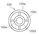
도 10a 내지 도 10c는 본 발명의 제5 실시예에 따른 가스 노즐의 사시도, 정면도 및 단면도이다.10A to 10C are a perspective view, a front view, and a sectional view of a gas nozzle according to a fifth embodiment of the present invention.
본 발명은 플라즈마 프로세스 챔버의 가스 노즐에 관한 것으로, 구체적으로는 공정 진행시 가스 노즐의 오염을 방지하도록 가스 노즐의 구조를 개선하여 플라즈마 프로세스 챔버의 세정 공정 효율을 향상시킬 수 있는 플라즈마 프로세스 챔버의 가스 노즐에 관한 것이다.The present invention relates to a gas nozzle of a plasma process chamber. Specifically, the gas of the plasma process chamber can be improved by improving the structure of the gas nozzle so as to prevent contamination of the gas nozzle during the process. Relates to a nozzle.
플라즈마는 다양한 산업 분야에 널리 사용되고 있으며 반도체 장치의 제조 공정에 있어서 예컨대, 세정(cleaning), 식각(etching), 증착(deposition) 등에 사용되고 있다. 반도체 장치의 제조 공정에서 플라즈마 프로세스 챔버는 작업 공정과 세정 공정이 교대적으로 진행된다. 고밀도 플라즈마(High Density Plasma; HDP)를 이용한 화학적 기상 증착(Chemical Vapor Deposition; CVD) 공정에서 플라즈마 프로세스 챔버는 통상 6매 정도의 웨이퍼를 가공하고 20분 내지 30분가량 소요되는 세정 공정을 교대적으로 진행한다.Plasma is widely used in various industrial fields, and is used in, for example, cleaning, etching, and deposition in the manufacturing process of semiconductor devices. In the manufacturing process of a semiconductor device, a plasma process chamber is alternately operated with a cleaning process. In Chemical Vapor Deposition (CVD) using High Density Plasma (HDP), the plasma process chamber typically processes six wafers and alternates a cleaning process that takes about 20 to 30 minutes. Proceed.
세정 공정에서 프로세스 챔버의 내부와 가스 노즐의 내측을 세정하게 되는데 상당 시간이 가스 노즐을 세정하는데 소요되고 있어 공정 수율을 저하시키는 주요 원인이 되고 있다. 이러한 원인은 가스 노즐의 구조적 취약점에 기인한 것으로, 프로세스 챔버의 내부에 장착되는 가스 노즐은 플라즈마 가스가 노즐의 내측으로 유입될 수밖에 없는 구조를 갖고 있기 때문 이다. 이러한 원인에 의해 가스 노즐의 내측으로 불순물이 증착되어 가스 노즐이 막히게 된다.In the cleaning process, the inside of the process chamber and the inside of the gas nozzle are cleaned, and a considerable time is required to clean the gas nozzle, which is a major cause of lowering the process yield. This is due to a structural weakness of the gas nozzle, because the gas nozzle mounted inside the process chamber has a structure in which plasma gas must flow into the nozzle. Due to this cause, impurities are deposited inside the gas nozzles, thereby clogging the gas nozzles.
가스 노즐의 세정 시간을 단축할 수 있는 가스 노즐이 제공된다면 플라즈마 프로세스 챔버의 전체적인 세정 공정 시간을 단축할 수 있어 공정 수율을 혁신적으로 향상 시킬 수 있을 것이다.If a gas nozzle is provided which can shorten the cleaning time of the gas nozzle, the overall cleaning process time of the plasma process chamber can be shortened, thereby improving the process yield.
본 발명은 상술한 문제점을 해결하기 위한 것으로, 그 목적은 가스 노즐의 불순물 증착에 의한 막힘 현상을 방지할 수 있는 플라즈마 프로세스 챔버의 가스 노즐을 제공하는데 있다.SUMMARY OF THE INVENTION The present invention has been made to solve the above problems, and an object thereof is to provide a gas nozzle of a plasma process chamber capable of preventing clogging due to impurity deposition of the gas nozzle.
이와 같은 목적을 달성하기 위하여, 본 발명의 플라즈마 프로세스 챔버의 내부에 장착되어 챔버 내부에 공정 가스를 분사하는 다수의 가스 노즐은: 소정 길이를 갖고 전단과 후단이 모두 개방된 관통형의 외관; 상기 외관의 내측에 순차적으로 매입 설치되도록 서로 다른 내경을 갖고, 전단과 후단이 모두 개방된 하나 이상의 관통형의 내관; 및 외관과 하나 이상의 내관이 각기 소정 간격을 갖도록 함과 아울러 노즐 내부의 간격을 더욱 좁게 분할하도록 내관의 외주면에 방사형으로 설치되는 다수의 지지부재를 갖는다.In order to achieve the above object, the plurality of gas nozzles mounted in the plasma process chamber of the present invention and spraying the process gas into the chamber include: a through-type exterior having both a predetermined length and open front and rear ends; At least one through-type inner tube having different inner diameters so as to be sequentially installed inwardly of the exterior, and open at both front and rear ends thereof; And a plurality of support members radially installed on the outer circumferential surface of the inner tube so that the outer tube and the one or more inner tubes each have a predetermined interval and further narrow the gap inside the nozzle.
이 실시예에 있어서, 가장 안쪽의 내관의 내측에 매입 설치되는 매입봉을 더 포함하고, 가장 안쪽의 내관과 매입봉은 다른 다수의 지지부재에 의해 지지되어 소정 간격을 갖는다.In this embodiment, it further includes a buried rod embedded in the innermost inner tube, the innermost inner tube and the buried rod is supported by a plurality of other support members to have a predetermined interval.
이 실시예에 있어서, 상기 내관은 외관 길이 이하의 길이를 갖는다.In this embodiment, the inner tube has a length less than the outer length.
이 실시예에 있어서, 상기 내관은 외관의 전단과 일치하거나 전방으로 돌출되거나 또는 후방으로 후진된 것 중 어느 하나로 위치한다.In this embodiment, the inner tube is positioned either to match the front end of the exterior, protrude forward or backward.
이 실시예에 있어서, 가스 노즐의 전면 출구의 간격을 방사형으로 다수 분할하도록 외관과 하나 이상의 내관 사이에 각기 설치되는 또 다른 다수의 지지부재를 포함한다.In this embodiment, it includes another plurality of support members each installed between the exterior and the one or more inner tubes to radially divide the spacing of the front exit of the gas nozzles.
이 실시예에 있어서, 매입봉의 후단은 경사를 갖고 전체적으로 원뿔형상을 갖는다.In this embodiment, the rear end of the embedding rod is inclined and generally conical.
본 발명의 다른 특징에 의하면, 플라즈마 프로세스 챔버의 내부에 장착되어 챔버 내부에 공정 가스를 분사하는 다수의 가스 노즐은: 소정 길이를 갖고 전단과 후단이 모두 개방된 관통형의 외관; 상기 외관의 내측에 설치되는 매입봉; 외관과 매입봉이 소정 간격을 갖도록 함과 아울러 노즐의 내부의 간격을 더욱 좁게 분할하도록 매입봉의 외주면에 방사형으로 설치되는 다수의 지지부재; 및 가스 노즐의 전면 출구에 환형으로 형성된 외관과 매입봉 사이의 간격에 설치되어 외관과 매입봉을 지지함과 아울러 출구를 보다 좁게 다수로 분할하도록 외관과 매입봉 사이에 설치되는 다른 다수의 지지부재를 포함한다.According to another feature of the present invention, a plurality of gas nozzles mounted inside the plasma process chamber to inject the process gas into the chamber include: a through-type exterior having a predetermined length and opening both front and rear ends; Buried rod is installed on the inside of the exterior; A plurality of support members radially installed on an outer circumferential surface of the embedding rod so as to have a predetermined interval between the exterior and the embedding rod, and to further narrow the gap between the inside of the nozzle; And a plurality of other supporting members installed at an interval between the outer ring and the buried rod formed in an annular shape at the front outlet of the gas nozzle to support the outer rod and the buried rod and to divide the outlet into a plurality of narrower outlets. It includes.
이 실시예에 있어서, 상기 매입봉은 길이 방향으로 그 중심부에 가스 흐름 경로를 제공하는 관통된 홀이 형성된다.In this embodiment, the buried rod is formed with a through hole that provides a gas flow path at its central portion in the longitudinal direction.
(실시예)(Example)
이하, 첨부한 도면들을 참조하여 본 발명의 바람직한 실시예들을 상세히 설명하기로 한다. 그러나 본 발명은 여기서 설명되어지는 실시예들에 한정되지 않고 다른 형태로 구체화될 수도 있다. 여기서 소개되는 실시예들은 개시된 내용이 철저하고 완전해질 수 있도록 그리고 당업자에게 본 발명의 사상이 충분히 전달될 수 있도록 하기 위해 제공되어지는 것이다.Hereinafter, exemplary embodiments of the present invention will be described in detail with reference to the accompanying drawings. However, the present invention is not limited to the embodiments described herein and may be embodied in other forms. The embodiments introduced herein are provided to make the disclosed contents thorough and complete, and to fully convey the spirit of the present invention to those skilled in the art.
본 발명은 플라즈마 프로세스 챔버의 가스 노즐이 플라즈마 가스가 역으로 유입되는 것을 방지하여 가스 노즐의 내측으로 불순물이 증착되는 것을 방지하여 결과적으로 플라즈마 프로세스 챔버의 세정 공정 시간을 단축시켜 공정 수율을 혁신적으로 향상 시킬 수 있도록 한다. 본 발명자는 이와 관련된 기술을 2003년 4월 19일자 국내 특허 출원 제10-2003-0024937호 고밀도 플라즈마 화학적 기상 증착 챔버 및 이를 위한 가스 노즐을 출원한 바 있다.The present invention prevents the gas nozzle of the plasma process chamber from flowing back to prevent the deposition of impurities into the inside of the gas nozzle, and consequently shortens the cleaning process time of the plasma process chamber, thereby significantly improving the process yield. Make it work. The present inventor has applied for the related technology, a high-density plasma chemical vapor deposition chamber and a gas nozzle for the same as Korean Patent Application No. 10-2003-0024937 dated April 19, 2003.
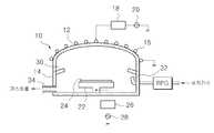
도 1a 및 도 1b는 본 발명과 관련된 플라즈마 프로세스 챔버의 수직 및 수평 단면도이다.1A and 1B are vertical and horizontal cross-sectional views of a plasma process chamber in accordance with the present invention.
도면을 참조하여, 고밀도 플라즈마(High Density Plasma; HDP) 화학적 기상 증착(Chemical Vapor Deposition; CVD) 챔버(이하, 'HDP CVD 챔버'라 약칭함)(10)는 챔버 상부(12)의 외측에 인덕터 코일(16)이 수회 감겨져 있다. 인덕터 코일(16)은 제1 주파수 발생기(20)로부터 발생되는 RF 신호를 매칭 네트웍(18)을 통해 제공받아 HDP CVD 챔버(10)의 내부로 플라즈마 이온화 에너지를 제공한다.Referring to the drawings, a High Density Plasma (HDP) Chemical Vapor Deposition (CVD) chamber (hereinafter abbreviated as 'HDP CVD chamber') 10 is an inductor outside the
HDP CVD 챔버(10)의 몸체(14)의 내측으로 다수의 가스 노즐(30)이 일정 간격 을 두고 다수개가 장착된다. 가스 노즐(30)은 가스 공급원(미도시)으로부터 제공되는 공정 가스를 챔버(10)의 내부로 고르게 분사한다. HDP CVD 챔버(10)의 하단 일측 모서리 부분에는 가스 배출구(34)가 마련된다. 가스 배출구(34)는 배기 시스템(미도시)과 연결된다. 도면에서 참조부호 32는 세정 가스 분사구이며 이는 원격 플라즈마 발생기(RPG)에 연결된다.A plurality of
가스 노즐(30)을 통해 공정 가스가 분사되고, 인덕터 코일(16)로부터 플라즈마 이온화 에너지가 공급되면 플라즈마가 발생된다. 이와 함께 제2 주파수 발생기(28)로부터 발생된 바이어스 전원이 서셉터(susceptor)(22)로 인가되어 작업편(work piece)(24) 예컨대 웨이퍼 상에 HDP CVD 공정이 진행된다. 여기서, 가스 노즐(30)은, 첨부도면 도 2 또는 도 3에 도시된 바와 같이, 공정이 진행되면서 플라즈마 가스가 역으로 유입되어 불순물이 증착되는 것을 방지하기 위한 구조를 갖는다.Process gas is injected through the
도 2a 및 도 2b는 도 1a의 플라즈마 프로세스 챔버에 장착된 가스 노즐의 일 예를 보여주는 단면도 및 정면도이다.2A and 2B are cross-sectional and front views illustrating an example of a gas nozzle mounted in the plasma process chamber of FIG. 1A.
도 2a 및 도 2b를 참조하여, 가스 노즐(30)은 소정 길이를 갖고 전단과 후단이 모두 개방된 외관(30a)과 외관(30a)의 내측에 매입봉(30b)이 설치된다. 매입봉(30b)은 외관(30a)과 소정 간격(30e) 예컨대 0.2mm에서 3mm의 간격을 갖도록 다수의 지지부재(30c)에 의해 지지된다. 매입봉(30b)은 외관(30a)의 길이보다 짧은 길이를 갖되 전단이 외관(30a)과 일치되게 매입 설치된다. 그리고 매입봉(30b)의 후단은 경사(30d)를 갖는 원뿔형상을 갖는다.Referring to FIGS. 2A and 2B, the
이와 같이, 가스 노즐(30)이 좁은 간격을 통해 공정 가스를 배출하게 되는 경우, 이 좁은 간격으로는 플라즈마 가스가 역으로 유입되지 않아 불순물이 가스 노즐의 내측으로 증착되는 것을 방지한다. 가스 노즐(30)은 전기적 절연체 예컨대, 세라믹 또는 알루미나 등으로 구성할 수 있다.As described above, when the
본 발명은 상술한바와 같은 플라즈마 프로세스 챔버의 가스 노즐의 구조를 좀더 발전시켜 불순물의 증착을 더욱 효과적으로 방지할 수 있는 가스 노즐을 제공한다. 본 발명의 가스 노즐은 상술한 HDP CVD 챔버뿐만 아니라 그 외에도 가스 노즐을 사용하는 모든 종류의 플라즈마 프로세스 챔버에 모두 적용가능하다.The present invention provides a gas nozzle that can further develop the structure of the gas nozzle of the plasma process chamber as described above to more effectively prevent the deposition of impurities. The gas nozzle of the present invention is applicable not only to the above-described HDP CVD chamber but also to all kinds of plasma process chambers using the gas nozzle.
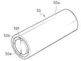
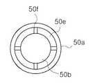
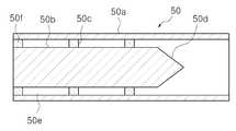
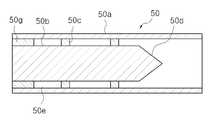
도 3a 내지 도 3d는 본 발명의 제1 실시예에 따른 가스 노즐의 사시도, 정면도 및 단면도이고, 도 4a 및 도 4b는 도 3a의 가스 노즐의 변형예를 보여주는 사시도이다.3A to 3D are perspective, front and sectional views of a gas nozzle according to a first embodiment of the present invention, and FIGS. 4A and 4B are perspective views showing a modification of the gas nozzle of FIG. 3A.
도면을 참조하여, 본 발명의 제1 실시예에 따른 플라즈마 프로세스 챔버의 가스 노즐(50)은 소정 길이를 갖고 전단과 후단이 모두 개방된 관통형의 외관(50a)과 외관(50a)의 내측에 매입봉(50b)이 설치된다. 매입봉(530b)은 외관(50a)과 소정 간격(50e) 예컨대 0.2mm에서 3mm의 간격을 갖도록 다수의 지지부재(50c)에 의해 지지된다. 지지부재(50c)는 매입봉(50b)과 일체로 구성될 수 있으며, 매입봉(50b)의 외주면을 따라 90°간격으로 방사형 구조로 배치될 수 있다. 매입봉(50b)은 외관(50a)의 길이보다 짧은 길이를 갖되 외관(50a)의 출구 전단과 일치되게 정렬되도록 매입 설치된다. 매입봉(30b)의 후단은 경사(30d)를 갖는 원뿔 형상을 갖는다.Referring to the drawings, the
가스 노즐(50)은 외관(50a)과 매입봉(50b) 사이의 간격(50e)이 환형을 갖게 되는데 제1 실시예에 따른 가스 노즐(50a)은 환형으로 형성되는 가스 노즐의 전면 출구의 간격(50e)을 다수로 분할할 수 있도록 또 다른 다수의 지지부재(50f)를 설치한다. 예를 들어, 방사형으로 배치된 4개의 또 다른 지지부재(50f)를 가스 노즐(50)의 출구에 90°간격으로 설치할 수 있고, 도 4a에 도시된 바와 같이, 방사형으로 배치되는 8개의 또 다른 지지부재(50f)를 일정 간격으로 설치할 수 있다. 이때, 도 3d에 도시된 바와 같이 가스 노즐(50)의 출구에 설치되는 다수의 지지부재(50g)는 그 길이를 비교적 길게 할 수 있다. 여기서, 도 4b에 도시된 바와 같이, 매입봉(50b')은 그 중심에 길이 방향으로 관통된 홀(50h)이 형성될 수 있으며, 이 홀(50h)을 통하여도 가스가 배출되도록 할 수도 있다.The
이와 같은 본 발명의 제1 실시예에 따른 가스 노즐(50)은 전면 출구의 환형으로 형성되는 간격(50e)을 다수로 분할하는 다수의 또 다른 지지부재(50f)를 설치함으로서 노즐 내부로 플라즈마 가스가 유입되는 것을 더욱 효과적으로 막을 수 있어 불순물이 노즐 내측으로 증착되는 것을 방지하게 된다. 즉, 다수의 지지부재(50f)는 지지 기능뿐만 아니라 가스 노즐(50)의 입구를 더욱 좁게 분할하여 플라즈마 가스가 역으로 유입되는 것을 더욱 어렵게 한다.The
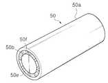
도 5a 내지 도 5c는 본 발명의 제2 실시예에 따른 가스 노즐의 사시도, 정면도 및 단면도이고, 도 6a 및 도 6b는 도 5a의 가스 노즐의 변형예를 보여주는 사시도이다.5A to 5C are perspective, front and sectional views of a gas nozzle according to a second embodiment of the present invention, and FIGS. 6A and 6B are perspective views showing a modification of the gas nozzle of FIG. 5A.
도면을 참조하여, 본 발명의 제2 실시예에 따른 플라즈마 프로세스 챔버의 가스 노즐(60)은 소정 길이를 갖고 전단과 후단이 모두 개방된 관통형의 외관(60a)과 그 내측에 삽입 장착되는 관통형의 내관(60f) 그리고 내관(60f)의 내측에 삽입 장착되는 매입봉(60b)을 구비한다. 이 실시예에서는 하나의 내관(60f)이 외관(60a)의 내측에 삽입되는 구성을 도시하였으나, 서로 다른 내경을 갖는 복수개의 내관이 순차적으로 중첩 매입될 수 있고 가장 안쪽의 내관에 매입봉(60b)이 삽입될 수 있다.Referring to the drawings, the
외관(60a)과 내관(60f) 그리고 매입봉(60b) 사이의 간격(60e)은 각기 0.2mm에서 3mm의 간격을 갖도록 다수의 지지부재(60c)에 의해 지지된다. 다수의 지지부재(60c)는 각기 내관(60f) 및 매입봉(60b)에 일체로 구성될 수 있으며, 내관(60f) 및 매입봉(60b)의 외주면을 따라 방사형으로 90°간격으로 배치될 수 있다. 내관(60f)과 매입봉(60b)은 외관(60a)의 길이보다 짧은 길이를 갖되 전체적으로 외관(60a)의 출구 전단과 일치되게 정렬된다. 매입봉(30b)의 후단은 경사(30d)를 갖는 원뿔 형상을 갖는다. 원뿔 형상을 갖도록 함으로서 가스 흐름을 막는 저항을 보다 적게 할 수 있다.The
도 6a 및 도 6b에 도시된 바와 같이, 가스 노즐(60)은 전면 출구의 환형으로 형성되는 간격(60e)을 다수로 분할할 수 있도록 또 다른 다수의 지지부재(60g)를 설치할 수 있다. 예를 들어, 도 6a에 도시된 바와 같이 각 간격에 각기 4개의 또 다른 지지부재(60g)를 90°간격으로 배치할 수 있다. 또는 도 6b에 도시된 바와 같이, 내측 간격에 4개의 또 다른 지지 부재를 방사형으로 90°간격으로 배치하고 외측 간격에는 8개의 또 다른 지지부재를 방사형으로 균등 간격으로 설치할 수 있다.As shown in FIGS. 6A and 6B, the
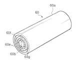
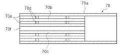
도 7a 내지 도 7c는 본 발명의 제3 실시예에 따른 가스 노즐의 사시도, 정면도 및 단면도이고, 도 8a 및 도 8b는 도 7a의 가스 노즐의 변형예를 보여주는 사시도이다.7A to 7C are perspective, front and sectional views of a gas nozzle according to a third embodiment of the present invention, and FIGS. 8A and 8B are perspective views illustrating a modification of the gas nozzle of FIG. 7A.
도면을 참조하여, 본 발명의 제3 실시예에 따른 플라즈마 프로세스 챔버의 가스 노즐(70)은 소정 길이를 갖고 전단과 후단이 모두 개방된 관통형의 외관(70a)과 그 내측에 순차적으로 삽입 장착되는 관통형의 제1 내관(70b) 및 제2 내관(70c)이 장착된다. 이 실시예에서는 서로 다른 내경을 갖는 두 개의 제1 및 제2 내관(70b, 70c)이 외관(60a)의 내측에 순차적으로 매입되는 구성을 도시하였으나, 서로 다른 내경을 갖는 둘 이상의 내관이 순차적으로 매입되어 중첩될 수 있다.Referring to the drawings, the
외관(70a)과 제1 및 제2 내관(70b, 70c) 사이의 간격(70e)은 각기 0.2mm에서 3mm의 간격을 갖도록 다수의 지지부재(70c)에 의해 지지된다. 가장 안쪽의 제2 내관(70c)의 내경(70f)은 각기 0.2mm에서 3mm를 갖도록 한다. 다수의 지지부재(60c)는 각기 제1 및 제2 내관(70b, 70c)에 일체로 구성될 수 있으며, 외주면을 따라 방사형으로 90°간격으로 배치될 수 있다. 제1 및 제2 내관(70b, 70c)은 외관(70a)의 길이보다 짧은 길이를 갖되 전체적으로 외관(70a)의 출구 전단과 일치되게 정렬된다.The
도 8a 및 도 8b에 도시된 바와 같이, 가스 노즐(70)은 전면 입구의 환형으로 형성되는 간격(70e)을 다수로 분할할 수 있도록 또 다른 다수의 지지부재(70g)를 방사형으로 설치할 수 있다. 예를 들어, 도 8a에 도시된 바와 같이, 각 간격에 각기 4개의 또 다른 지지부재(70g)를 방사형으로 90°간격으로 배치할 수 있다. 또는, 도 8b에 도시된 바와 같이, 내측 간격에 4개의 또 다른 지지 부재를 방사형으로 90°간격으로 배치하고 외측 간격에는 8개의 또 다른 지지부재를 방사형으로 균등 간격으로 설치할 수 있다.As shown in FIGS. 8A and 8B, the
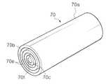
도 9a 내지 도 9c는 본 발명의 제4 실시예에 따른 가스 노즐의 사시도, 정면도 및 단면도이다.9A to 9C are a perspective view, a front view, and a sectional view of a gas nozzle according to a fourth embodiment of the present invention.
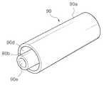
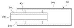
도면을 참조하여, 본 발명의 제4 실시예에 따른 플라즈마 프로세스 챔버의 가스 노즐(90)은 소정 길이를 갖고 전단과 후단이 모두 개방된 관통형의 외관(90a)과 그 내측에 삽입 장착되는 관통형의 내관(90b)이 장착된다. 이 실시예에서는 하나의 내관(90b)이 외관(60a)의 내측에 삽입되는 구성을 도시하였으나, 서로 다른 내경을 갖는 둘 이상의 내관이 순차적으로 매입되어 중첩될 수 있다.Referring to the drawings, the
외관(90a)과 내관(90b) 사이의 간격(90d)은 0.2mm에서 3mm의 간격을 갖도록 방사형으로 배치된 다수의 지지부재(90c)에 의해 지지된다. 내관(90c)의 내경(90e)은 0.2mm에서 3mm를 갖도록 한다. 다수의 지지부재(90c)는 내관(90c)에 일체로 구성될 수 있으며, 외주면을 따라 90°간격으로 배치될 수 있다. 내관(90b)은 외관(90a)의 길이와 동일하거나 짧은 길이를 갖되 외관(90a)의 전단으로 대략 1mm 내지 10mm가 돌출된다.The
도 10a 내지 도 10c는 본 발명의 제5 실시예에 따른 가스 노즐의 사시도, 정면도 및 단면도이다.10A to 10C are a perspective view, a front view, and a sectional view of a gas nozzle according to a fifth embodiment of the present invention.
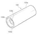
도면을 참조하여, 본 발명의 제5 실시예에 따른 플라즈마 프로세스 챔버의 가스 노즐(100)은 소정 길이를 갖고 전단과 후단이 모두 개방된 관통형의 외관(100a)과 그 내측에 삽입 장착되는 관통형의 내관(100b)이 장착된다. 이 실시예에서는 하나의 내관(100b)이 외관(100a)의 내측에 삽입되는 구성을 도시하였으나, 둘 이상의 내관이 순차적으로 삽입되어 중첩될 수 있다.Referring to the drawings, the
외관(100a)과 내관(100b) 사이의 간격(100d)은 0.2mm에서 3mm의 간격을 갖도록 다수의 지지부재(100c)에 의해 지지된다. 내관(100c)의 내경(100e)은 0.2mm에서 3mm를 갖도록 한다. 다수의 지지부재(100c)는 내관(100c)에 일체로 구성될 수 있으며, 외주면을 따라 방사형으로 90°간격으로 배치될 수 있다. 내관(100b)은 외관(100a)의 길이 보다 짧은 길이를 갖고 외관(90a)의 전단에서 대략 1mm 내지 10mm 후방에 설치된다.The
이상과 같이, 본 발명의 제1 내지 제5 실시예와 그 변형예들에 따른 가스 노즐은 그 전면 입구가 좁은 간격을 갖도록 되어 있어서 그 좁은 간격으로는 플라즈마 가스가 역으로 유입되지 않아 불순물이 가스 노즐의 내측으로 증착되는 것을 방지한다. 더욱이, 다수의 지지부재는 지지 기능뿐만 아니라 가스 노즐의 내부 간격을 더욱 좁게 분할하여 플라즈마 가스가 역으로 유입되는 것을 더욱 어렵게 한다.As described above, the gas nozzles according to the first to fifth embodiments of the present invention and the modifications thereof have a narrow space at the front inlet thereof, so that the plasma gas does not flow into the reverse space at the narrow space so that impurities are not generated. Prevents deposition into the interior of the nozzle. Moreover, the plurality of support members further narrows the internal spacing of the gas nozzles as well as the support function, making it more difficult for the plasma gas to flow back.
가스 노즐은 전기적 절연체 예컨대, 세라믹 또는 알루미나 등으로 구성할 수 있다. 본 발명의 가스 노즐은 플라즈마 프로세스 챔버의 내부에 장착되는데 그 장착 위치는 본 발명에 있어서 한정적인 요소가 아님으로 구체적인 설명은 생략한다.The gas nozzle may be made of an electrical insulator such as ceramic or alumina or the like. The gas nozzle of the present invention is mounted inside the plasma process chamber, and the mounting position thereof is not a limiting element in the present invention, and thus a detailed description thereof will be omitted.
이상에서 본 발명에 따른 플라즈마 프로세스 챔버의 가스 노즐의 구성 및 작용을 상기한 설명 및 도면에 따라 도시하였으나, 본 발명의 기술적 사상을 벗어나지 않는 범위 내에서 다양한 변화 및 변경이 가능하며 각 실시예들은 상호 복합적으로 응용하여 구성이 가능함은 물론이다.Although the configuration and operation of the gas nozzle of the plasma process chamber according to the present invention have been described in accordance with the above description and the drawings, various changes and modifications can be made without departing from the technical spirit of the present invention. Of course, it is possible to configure a complex application.
이상에서 상세하게 설명한 바에 의하면, 본 발명의 플라즈마 프로세스 챔버의 가스 노즐은 그 내측으로 플라즈마 가스가 유입되는 것을 막아 내부에 불순물이 증착되는 것을 방지하여 프로세스 챔버의 세정 시간을 단축시켜 공정 수율을 향상 시키는 효과가 있다.As described in detail above, the gas nozzle of the plasma process chamber of the present invention prevents plasma gas from flowing into the inside thereof, thereby preventing impurities from being deposited therein, thereby shortening the cleaning time of the process chamber and improving process yield. It works.
Claims (12)
Translated fromKoreanPriority Applications (1)
| Application Number | Priority Date | Filing Date | Title |
|---|---|---|---|
| KR1020050097151AKR100586639B1 (en) | 2005-10-14 | 2005-10-14 | Gas nozzle in plasma process chamber |
Applications Claiming Priority (1)
| Application Number | Priority Date | Filing Date | Title |
|---|---|---|---|
| KR1020050097151AKR100586639B1 (en) | 2005-10-14 | 2005-10-14 | Gas nozzle in plasma process chamber |
Related Parent Applications (1)
| Application Number | Title | Priority Date | Filing Date |
|---|---|---|---|
| KR1020030039084ADivisionKR100629990B1 (en) | 2003-06-17 | 2003-06-17 | Gas nozzle in plasma process chamber |
Publications (2)
| Publication Number | Publication Date |
|---|---|
| KR20050103182A KR20050103182A (en) | 2005-10-27 |
| KR100586639B1true KR100586639B1 (en) | 2006-06-08 |
Family
ID=37281214
Family Applications (1)
| Application Number | Title | Priority Date | Filing Date |
|---|---|---|---|
| KR1020050097151AExpired - Fee RelatedKR100586639B1 (en) | 2005-10-14 | 2005-10-14 | Gas nozzle in plasma process chamber |
Country Status (1)
| Country | Link |
|---|---|
| KR (1) | KR100586639B1 (en) |
- 2005
- 2005-10-14KRKR1020050097151Apatent/KR100586639B1/ennot_activeExpired - Fee Related
Also Published As
| Publication number | Publication date |
|---|---|
| KR20050103182A (en) | 2005-10-27 |
Similar Documents
| Publication | Publication Date | Title |
|---|---|---|
| US11993847B2 (en) | Injector | |
| KR100862658B1 (en) | Gas injection device of semiconductor processing system | |
| KR100485015B1 (en) | Gas injection slit nozzle for a plasma process reactor | |
| JP4430003B2 (en) | High density plasma chemical vapor deposition system | |
| KR100997104B1 (en) | Shower head for semiconductor manufacturing and semiconductor manufacturing apparatus provided with this shower head | |
| JP2009302324A (en) | Gas ring, semiconductor substrate processing device, and semiconductor substrate processing method | |
| KR100520980B1 (en) | High density plasma chemical vapor deposition chamber and gas nozzle therefor | |
| US20050092245A1 (en) | Plasma chemical vapor deposition apparatus having an improved nozzle configuration | |
| KR100712728B1 (en) | Cleaning device for gas separation shower head | |
| KR20040108480A (en) | Gas nozzle of plasma process chamber | |
| KR100586639B1 (en) | Gas nozzle in plasma process chamber | |
| US20040144492A1 (en) | Plasma processing device | |
| KR102438551B1 (en) | Gas supply device for exhaust gas plasma processing equipment and exhaust gas plasma processing equipment having the same | |
| KR100520979B1 (en) | Vacuum process chamber remote plasma generator | |
| KR101183140B1 (en) | Process apparatus which uses pulse RF power, and method of processing a substrate using the same | |
| KR100578138B1 (en) | Injection pipe used in a plasma treating apparatus, and plasma chemical vapor deposition apparatus with the injection pipe | |
| KR100941073B1 (en) | Top nozzle and substrate processing unit | |
| KR20080060782A (en) | Gas nozzles and plasma chemical vapor deposition facilities comprising them | |
| KR20030037873A (en) | A gas nozzle for semiconductor processing apparatus | |
| KR100918676B1 (en) | Evaporator with Shower Head | |
| KR101007821B1 (en) | Gas injection device for semiconductor manufacturing | |
| KR100688479B1 (en) | Plasma Chemical Vapor Deposition Chamber for Uniform Cleaning Gas Delivery | |
| KR20050050209A (en) | High density plasma chemical vapor deposition apparatus for generating uniform thin film | |
| KR20030035370A (en) | Gas injector for chemical vapor deposition apparatus | |
| KR200252071Y1 (en) | Etching chamber for wafer |
Legal Events
| Date | Code | Title | Description |
|---|---|---|---|
| A107 | Divisional application of patent | ||
| A201 | Request for examination | ||
| PA0107 | Divisional application | St.27 status event code:A-0-1-A10-A16-div-PA0107 St.27 status event code:A-0-1-A10-A18-div-PA0107 | |
| PA0201 | Request for examination | St.27 status event code:A-1-2-D10-D11-exm-PA0201 | |
| PG1501 | Laying open of application | St.27 status event code:A-1-1-Q10-Q12-nap-PG1501 | |
| E902 | Notification of reason for refusal | ||
| PE0902 | Notice of grounds for rejection | St.27 status event code:A-1-2-D10-D21-exm-PE0902 | |
| P11-X000 | Amendment of application requested | St.27 status event code:A-2-2-P10-P11-nap-X000 | |
| P13-X000 | Application amended | St.27 status event code:A-2-2-P10-P13-nap-X000 | |
| R17-X000 | Change to representative recorded | St.27 status event code:A-3-3-R10-R17-oth-X000 | |
| E701 | Decision to grant or registration of patent right | ||
| PE0701 | Decision of registration | St.27 status event code:A-1-2-D10-D22-exm-PE0701 | |
| GRNT | Written decision to grant | ||
| PR0701 | Registration of establishment | St.27 status event code:A-2-4-F10-F11-exm-PR0701 | |
| PR1002 | Payment of registration fee | Fee payment year number:1 St.27 status event code:A-2-2-U10-U11-oth-PR1002 | |
| PG1601 | Publication of registration | St.27 status event code:A-4-4-Q10-Q13-nap-PG1601 | |
| PR1001 | Payment of annual fee | Fee payment year number:4 St.27 status event code:A-4-4-U10-U11-oth-PR1001 | |
| R18-X000 | Changes to party contact information recorded | St.27 status event code:A-5-5-R10-R18-oth-X000 | |
| PR1001 | Payment of annual fee | Fee payment year number:5 St.27 status event code:A-4-4-U10-U11-oth-PR1001 | |
| L13-X000 | Limitation or reissue of ip right requested | St.27 status event code:A-2-3-L10-L13-lim-X000 | |
| U15-X000 | Partial renewal or maintenance fee paid modifying the ip right scope | St.27 status event code:A-4-4-U10-U15-oth-X000 | |
| PR1001 | Payment of annual fee | Fee payment year number:6 St.27 status event code:A-4-4-U10-U11-oth-PR1001 | |
| PR1001 | Payment of annual fee | Fee payment year number:7 St.27 status event code:A-4-4-U10-U11-oth-PR1001 | |
| R18-X000 | Changes to party contact information recorded | St.27 status event code:A-5-5-R10-R18-oth-X000 | |
| R17-X000 | Change to representative recorded | St.27 status event code:A-5-5-R10-R17-oth-X000 | |
| R18-X000 | Changes to party contact information recorded | St.27 status event code:A-5-5-R10-R18-oth-X000 | |
| FPAY | Annual fee payment | Payment date:20130527 Year of fee payment:8 | |
| PR1001 | Payment of annual fee | Fee payment year number:8 St.27 status event code:A-4-4-U10-U11-oth-PR1001 | |
| FPAY | Annual fee payment | Payment date:20140526 Year of fee payment:9 | |
| PR1001 | Payment of annual fee | Fee payment year number:9 St.27 status event code:A-4-4-U10-U11-oth-PR1001 | |
| PN2301 | Change of applicant | St.27 status event code:A-5-5-R10-R11-asn-PN2301 St.27 status event code:A-5-5-R10-R13-asn-PN2301 | |
| LAPS | Lapse due to unpaid annual fee | ||
| PC1903 | Unpaid annual fee | Not in force date:20150530 Payment event data comment text:Termination Category : DEFAULT_OF_REGISTRATION_FEE St.27 status event code:A-4-4-U10-U13-oth-PC1903 | |
| R18-X000 | Changes to party contact information recorded | St.27 status event code:A-5-5-R10-R18-oth-X000 | |
| PC1903 | Unpaid annual fee | Ip right cessation event data comment text:Termination Category : DEFAULT_OF_REGISTRATION_FEE Not in force date:20150530 St.27 status event code:N-4-6-H10-H13-oth-PC1903 | |
| P22-X000 | Classification modified | St.27 status event code:A-4-4-P10-P22-nap-X000 | |
| P22-X000 | Classification modified | St.27 status event code:A-4-4-P10-P22-nap-X000 | |
| R18-X000 | Changes to party contact information recorded | St.27 status event code:A-5-5-R10-R18-oth-X000 | |
| R18-X000 | Changes to party contact information recorded | St.27 status event code:A-5-5-R10-R18-oth-X000 |