KR100585293B1 - Optical Signal Wavelength Channel Meter - Google Patents
Optical Signal Wavelength Channel MeterDownload PDFInfo
- Publication number
- KR100585293B1 KR100585293B1KR1020050026076AKR20050026076AKR100585293B1KR 100585293 B1KR100585293 B1KR 100585293B1KR 1020050026076 AKR1020050026076 AKR 1020050026076AKR 20050026076 AKR20050026076 AKR 20050026076AKR 100585293 B1KR100585293 B1KR 100585293B1
- Authority
- KR
- South Korea
- Prior art keywords
- optical
- wavelength
- optical signal
- filter
- wavelength channel
- Prior art date
- Legal status (The legal status is an assumption and is not a legal conclusion. Google has not performed a legal analysis and makes no representation as to the accuracy of the status listed.)
- Expired - Fee Related
Links
Images


Classifications
- H—ELECTRICITY
- H04—ELECTRIC COMMUNICATION TECHNIQUE
- H04J—MULTIPLEX COMMUNICATION
- H04J14/00—Optical multiplex systems
- H04J14/02—Wavelength-division multiplex systems
- G—PHYSICS
- G02—OPTICS
- G02B—OPTICAL ELEMENTS, SYSTEMS OR APPARATUS
- G02B6/00—Light guides; Structural details of arrangements comprising light guides and other optical elements, e.g. couplings
- G02B6/24—Coupling light guides
- G02B6/26—Optical coupling means
- G02B6/28—Optical coupling means having data bus means, i.e. plural waveguides interconnected and providing an inherently bidirectional system by mixing and splitting signals
- G02B6/293—Optical coupling means having data bus means, i.e. plural waveguides interconnected and providing an inherently bidirectional system by mixing and splitting signals with wavelength selective means
- G02B6/29304—Optical coupling means having data bus means, i.e. plural waveguides interconnected and providing an inherently bidirectional system by mixing and splitting signals with wavelength selective means operating by diffraction, e.g. grating
- H—ELECTRICITY
- H04—ELECTRIC COMMUNICATION TECHNIQUE
- H04B—TRANSMISSION
- H04B10/00—Transmission systems employing electromagnetic waves other than radio-waves, e.g. infrared, visible or ultraviolet light, or employing corpuscular radiation, e.g. quantum communication
- H04B10/07—Arrangements for monitoring or testing transmission systems; Arrangements for fault measurement of transmission systems
- H04B10/071—Arrangements for monitoring or testing transmission systems; Arrangements for fault measurement of transmission systems using a reflected signal, e.g. using optical time domain reflectometers [OTDR]
Landscapes
- Physics & Mathematics (AREA)
- Engineering & Computer Science (AREA)
- Computer Networks & Wireless Communication (AREA)
- Signal Processing (AREA)
- Electromagnetism (AREA)
- General Physics & Mathematics (AREA)
- Optics & Photonics (AREA)
- Spectrometry And Color Measurement (AREA)
Abstract
Translated fromKoreanDescription
Translated fromKorean도 1은 본 발명에 따른 광신호 파장 채널 측정기의 일 실시예도.1 is an embodiment of an optical signal wavelength channel meter according to the present invention;
도 2는 도 1의 각부의 파형도.FIG. 2 is a waveform diagram of each part of FIG. 1. FIG.
도 3은 도 1의 광파장 채널 표준기의 일 실시예도.3 is an embodiment of the optical wavelength channel standard of FIG.
도 4 및 도 5는 도 3의 광 필터의 구성도.4 and 5 are configuration diagrams of the optical filter of FIG.
도 6는 도 1의 광파장 채널 표준기의 다른 실시예도.6 is another embodiment of the optical wavelength channel standard of FIG.
도 7은 도 6의 각부의 파형도.7 is a waveform diagram of each part of FIG. 6;
도 8은 도 1의 변형 예도.8 is a modified example of FIG.
도 9은 본 발명에 따른 광신호 파장 채널 측정기의 다른 실시예도.9 is another embodiment of an optical signal wavelength channel meter according to the present invention;
도 10은 본 발명에 따른 광신호 파장 채널 측정기의 또 다른 실시예도.10 is yet another embodiment of an optical signal wavelength channel meter in accordance with the present invention.
도 11은 도 10의 정밀가변필터의 상세 구성도.11 is a detailed block diagram of the precision variable filter of FIG.
도 12는 본 발명의 각 출력 표시기를 나타낸 도.12 illustrates each output indicator of the present invention.
<도면의 주요부분에 대한 부호의 설명><Description of Symbols for Main Parts of Drawings>
110,330 : 파장가변필터110,330 Wavelength Tunable Filter
120,143,220,250,310,340 : 광신호 분리기 120,143,220,250,310,340: Optical Signal Separator
130,142,145,147,230,260,320,350 : 광검출기130,142,145,147,230,260,320,350: Photodetector
140,270,360 : 광파장 채널 표준기 148,150,280,370 : 신호 처리기140,270,360: Optical Wavelength Channel Standard 148,150,280,370: Signal Processor
141,144 : 광필터 146 : 파장 표준 흡수셀141,144
150 : 표준 광원 160 : 광스위치150: standard light source 160: optical switch
210 : 광대역 가변필터 240 : 정밀가변필터210: wide band variable filter 240: precision variable filter
본 발명은 광신호 파장 채널 측정기에 관한 것으로, 특히 파장분할다중 광통신에서 사용되는 광원 및 광소자들의 파장 특성을 측정하는 광신호 파장 채널 측정기에 관한 것이다.BACKGROUND OF THE INVENTION 1. Field of the Invention The present invention relates to an optical signal wavelength channel meter, and more particularly, to an optical signal wavelength channel meter for measuring wavelength characteristics of light sources and optical elements used in wavelength division multiplexed optical communication.
현재 세계의 통신 업계들은 인터넷, 멀티미디어 서비스 등의 발전에 따라 폭발적인 전송 속도의 증가를 예측하고 있다. 이와 더불어 각 국가들은 자국의 국가 경쟁력 증대의 차원에서 초고속 정보통신망의 구축을 핵심적인 국가 사업으로 지원하고 있는 실정이다.Currently, the world's telecommunications industry anticipates the explosive increase in transmission speed as the Internet and multimedia services are developed. In addition, each country supports the construction of high-speed information and communication networks as a core national project in order to increase its national competitiveness.
AT&T 의 경우 매년 12% 이상의 속도 증가를 예측하고 있으며, 한국통신의 경우도 2015년에 이르면 현재의 통신량에 비해 약 130배 정도의 통신량 증가를 예상하고 있다. 이러한 현실 속에서 여러 가지 통신속도 증가 방법들이 제시되어 왔었다.AT & T expects a speed increase of more than 12% annually, and KT expects to increase its traffic by about 130 times compared to the current traffic by 2015. In this reality, various communication speed increasing methods have been proposed.
이를 크게 세가지로 구분하자면 전자회로의 속도를 증가시키는 방법(TDM : Time Division Multiplexing), 광학적으로 짧은 펄스를 만들어 이를 다중화 하는 방법(OTDM : Optical Time Division Multiplexing), 그리고 여러 가지 다른 파장을 묶어 한 개의 광섬유를 통해 전송하는 파장분할 다중화 방법(WDM : Wavelength Division Multiplexing) 등이라 할 수 있다.There are three major ways to increase the speed of electronic circuits (TDM: Time Division Multiplexing), optically short pulses to multiplex them (OTDM: Optical Time Division Multiplexing), and Wavelength Division Multiplexing (WDM) for transmitting through an optical fiber.
이중 WDM 전송 기술은 불과 수년 전 그 개념이 처음 나온 이후, 전세계적으로 연구가 되어왔고 현재는 상용 장비가 나올 정도로 빠른 진전이 있었다. 이 기술은 전송 속도에 상관없이 여러 채널을 각각 다른 파장에 실어줌으로써 한 개의 광섬유 코어를 이용해 전송해주는 방법으로 향후 초고속 정보통신망의 광통신 분야에서 핵심 기술로 이용될 것이다.Dual WDM transmission technology has been studied around the world since its inception just a few years ago and is now making rapid progress in commercial equipment. This technology will be used as a core technology in the optical communication field of the high-speed information communication network in the future by using a single optical fiber core by loading several channels at different wavelengths regardless of the transmission speed.
광섬유의 큰 매력 중 하나는 매우 넓은 주파수 영역에 걸쳐 통신이 가능하다는 점이다. 2dB/km의 손실을 기준으로 한다면 약 130THz 구간(100nm)의 대역폭을 가지게 된다(참고 : THz=1012Hz). 현재까지의 광통신 기술은 이 넓은 전송 가능 구간 중 1310nm 부근에서 단지 수백 MHz~수 GHz 폭의 한 채널만 사용해 왔었다. WDM 전송은 이 넓은 대역을 최대한 활용해 보자는 생각에서 출발한 전송 방법이다.One of the great appeals of fiber optics is their ability to communicate over a very wide frequency range. Based on the loss of 2dB / km, it has a bandwidth of about 130 THz section (100 nm) (Note: THz = 1012 Hz). Up to now, optical communication technology has used only one channel of hundreds of MHz to several GHz in the vicinity of 1310nm of this wide transmission range. WDM transmission is a transmission method that started with the idea of making the most of this wide band.
현재 사용되고 있는 파장은 1310nm 영역과 1550nm 영역이다. 최근 1550nm 영역에서 동작하는 에르븀 첨가 광증폭기(EDFA)의 발전으로 말미암아 파장분할 다중화의 연구는 주로 이 파장 부근에서 이루어지고 있다. 여기에서 일정한 파장 간격으로 채널을 배치하여 각 채널에 신호를 실은 후, 여러 채널을 광학적으로 다중화하여 한 개의 광섬유를 통해 전송하게 된다. 지금까지는 한 개의 광섬유 코어에 한 개의 파장만을 실어 보냈으나, WDM 전송에서는 여러 개의 파장을 하나로 묶어서 보내며, 수신 측에서는 각 채널을 파장별로 분해하여 각 채널을 별도로 활용한다.Currently used wavelengths are 1310 nm and 1550 nm. Recent advances in erbium-doped optical amplifiers (EDFAs) operating in the 1550 nm range have led to the study of wavelength division multiplexing mainly near this wavelength. Here, the channels are arranged at regular wavelength intervals to load signals on each channel, and then optically multiplexed and transmitted through one optical fiber. Until now, only one wavelength is sent to one optical fiber core, but in WDM transmission, multiple wavelengths are bundled and sent. On the receiving side, each channel is separated by wavelength to utilize each channel separately.
최근 들어 파장분할다중화 방식을 이용한 광가입자망 기술 즉, WDM-PON 기술의 개발과 이를 보급하려는 움직임이 높아지고 있다. 이러한 WDN-PON 가입자의 보급과 운용에 있어서는 관련 광송신 소자 및 수동 광소자들의 파장 특성의 측정이 수시로 필요하게 되며, 향후 일반 운용 요원들이 항상 휴대하여 가지고 다니며 측정을 해야 하는 장치가 필요하다.Recently, the development of optical subscriber network technology using wavelength division multiplexing method, that is, WDM-PON technology and the movement to spread it are increasing. In the dissemination and operation of such WDN-PON subscribers, measurement of wavelength characteristics of related optical transmitters and passive optical devices is required from time to time, and devices that need to be carried and measured by general operation personnel in the future are needed.
한편, 종래 광신호의 파장을 측정하는 측정기로는 광 스펙트럼 분석기(Optical Spectrum Analyser)와 파장 측정기(Wavelength Meter 혹은 Wavemeter)가 있다.Meanwhile, conventional measuring instruments for measuring the wavelength of an optical signal include an optical spectrum analyzer (Optical Spectrum Analyzer) and a wavelength meter (Wavelength Meter or Wavemeter).
광 스펙트럼 분석기는 주로 회절격자를 이용하는 구조로 이루어져 광신호의 스펙트럼 분석과 출력을 측정하고 대부분 벌크(Bulk)형 정밀 광학기기로 이루어져 있어 고가 및 부피가 크고 전력 소모가 많은 구조를 갖는 단점이 있다.The optical spectrum analyzer mainly consists of a structure using a diffraction grating, and has a disadvantage in that it is expensive, bulky, and power consuming because it mainly consists of bulk type precision optics.
또한, 파장 측정기는 페브리-페롯 간섭계 필터를 이용하여 주로 레이저의 발진 파장의 절대 값과 정밀 파장 값을 측정하는 장치이나 이 장치 또는 정밀 광학기기로 구성된 구조를 가지고 있어 아울러 연속적인 파장 스펙트럼 분석에는 불리하고 충격에도 안정된 소형 및 휴대성 기기로는 다소 부적합한 단점이 있다.In addition, the wavelength measuring device is a device that mainly measures the absolute and precise wavelength values of the oscillation wavelength of a laser using a Fabry-Perot interferometer filter, or a structure composed of this device or precision optics. The disadvantages are that the small and portable devices which are disadvantageous and stable against impact are somewhat unsuitable.
이와 같이 종래 광신호의 파장 특성 측정 장치는 휴대성이 낮고 충격에 약한 벌크형 정밀 광학구조를 가지고 있으며, 고가의 장비들로 구성이 되어 있는 단점이 있다.As such, the wavelength characteristic measuring apparatus of the conventional optical signal has a bulky precision optical structure that is low in portability and weak in impact, and has a disadvantage of being composed of expensive equipments.
종래 광신호의 파장을 측정하는 측정장치에 대하여 보다 구체적으로 살펴보면 다음과 같다.Looking at the measurement apparatus for measuring the wavelength of the conventional optical signal in more detail as follows.
"Fiber optic test and measurement"[Dennis Derickson(editor), Prentice Hall, New Jersey(1998), Chapters 3 및 4와 더불어 이 책자에서 제시한 관련 참고문헌]에서는 파장가변필터, 페브리-페롯 필터, 마이켈슨 간섭계, 회절격자 등을 이용하여 광 스펙트럼을 분석하는 장치와 광파장 측정기에 대한 동작 원리와 구조들에 대해서 기술하고 있다. 아울러 이들 광 스펙트럼 분석 장치와 광 파장 측정기의 절대 파장 측정을 위한 파장 표준기로 흡수 가스셀을 이용하는 도구와 원리를 기술하고 있다. 그러나 이 참고문헌에서는 파장가변 필터와 더불어 일정한 파장(또는 주파수) 간격의 파장 표준기를 동시에 이용하여 규격화된 파장 채널을 분석하는 구체적인 구도에 대해서는 제시하지 않고 있다.Fiber optic test and measurement (Dennis Derickson (editor), Prentice Hall, New Jersey (1998), Chapters 3 and 4, and related references in this booklet) discusses wavelength-variable filters, Fabry-Perot filters, The principles and structures of the optical spectrum analyzer and device for analyzing the light spectrum using kelson interferometers and diffraction gratings are described. We also describe the tools and principles of using absorbing gas cells as wavelength standards for absolute wavelength measurements of these optical spectrum analyzers and optical wavelength gauges. However, this reference does not provide a detailed structure for analyzing a standardized wavelength channel using a wavelength variable filter and a wavelength standard with a constant wavelength (or frequency) interval.
다음, US 6,587,214(July 1, 2003)에서는 빔 분리기와 페브리 페롯 에탈론(Fabry-Perot etalon), 그리고 박막필터를 이용하여 파장분할다중 광신호의 파장 및 출력을 측정하는 구도를 제시하고 있으나, 이 특허에서는 고정된 필터들을 이용하여 고정된 파장에 대한 특성만 측정하는 구도에 관련되어 있어 파장이 변화하는 특성의 관측이 어렵다.Next, US 6,587,214 (July 1, 2003) proposes a composition for measuring the wavelength and output of a wavelength-division multiplex optical signal using a beam splitter, Fabry-Perot etalon, and a thin film filter. In this patent, it is difficult to observe the characteristic of changing wavelength because it is related to the composition of measuring only the characteristic of fixed wavelength using fixed filters.
US 5,898,502(April 27, 1999)에서는 방향성 광커플러와 고정형 광필터, 광검출기 등을 이용하여 고정된 파장 채널의 각각에 대한 파장 채널을 감시 및 측정하는 구도를 보여주고 있으나, 입력 광신호의 연속적인 파장 분포 특성의 측정이 용이하지 않은 단점이 있다.US 5,898,502 (April 27, 1999) shows a method for monitoring and measuring wavelength channels for each of fixed wavelength channels using a directional optocoupler, a fixed optical filter, and a photodetector. There is a disadvantage that the measurement of the wavelength distribution characteristic is not easy.
US Publication No. 2003/0076503(April 24, 2003, Published dated)의 경우에는 주기적인 파장 간격의 광 간섭계 필터를 이용하되 두개의 서로 다른 파장 간격을 가진 광 간섭계 필터를 이용하여 광신호의 파장을 측정하는 구도로서 넓은 파장 영역에서의 고속 파장 신호 확인을 위해 고정형 광대역 광필터를 이용하는 구도와 파장 표준화를 위한 흡수 가스 셀을 이용하는 구도를 제안하고 있다. 그러나 이 구도에서는 입력 광신호의 연속적인 파장 분포 특성의 측정이 용이하지 않은 단점이 있다.US Publication No. In the case of 2003/0076503 (April 24, 2003, Published dated), an optical interferometer filter with periodic wavelength intervals is used, but an optical interferometer filter with two different wavelength intervals is used to measure the wavelength of an optical signal. In order to identify high-speed wavelength signals in the wavelength region, a composition using a fixed broadband optical filter and an absorption gas cell for wavelength standardization are proposed. However, this composition has a disadvantage in that it is not easy to measure the continuous wavelength distribution characteristic of the input optical signal.
US 6,043,883(March 28, 2000)은 빔 분파기, 복굴절률 지연판(Birefringgent Retardation Plate), 편광 광분파기, 광검출기 등을 사용하여 정밀 광파장 측정 구도를 제안하고 있으나, 이 구도에서는 마찬가지로 입력 광신호의 연속적인 파장 분포 특성의 측정과 정해진 파장 간격에 맞는 채널의 빠른 확인 유무가 용이하지 않은 단점이 있다.US Pat. No. 6,043,883 (March 28, 2000) proposes a precise optical wavelength measurement scheme using a beam splitter, a birefringent retardation plate, a polarized optical splitter, a photodetector, and the like. It is not easy to measure the continuous wavelength distribution and to quickly identify a channel within a predetermined wavelength interval.
US Publication No. 2002/0163646(Nov. 7, 2002, Published dated)의 파장 측정기에서는 팔 길이가 다른 광 간섭계, 편광기, 높은 복굴절률의 광섬유, 편광 광 분파기, 광검출기 등을 이용하여 파장이 변화하는 레이저의 실시간 파장 교정 시스템과 파장 측정 구도에 관한 구도와 더불어 가스 흡수 셀을 이용한 절대 파장 표준화 구도를 제안하고 있다. 이 구도에서는 입력 광신호의 연속적인 파장 분포 특성의 측정이 용이하지 않은 단점이 있다.US Publication No. The wavelength meter of 2002/0163646 (Nov. 7, 2002, Published dated) uses real-time lasers with varying wavelengths using optical interferometers, polarizers with different arm lengths, high birefringence optical fibers, polarized light splitters, and photodetectors. In addition to the composition of the wavelength calibration system and the composition of wavelength measurement, an absolute wavelength standardization scheme using gas absorption cells is proposed. In this composition, it is not easy to measure the continuous wavelength distribution characteristic of the input optical signal.
본 발명은 이러한 점을 감안한 것으로, 본 발명의 목적은 광통신 기술의 파장 채널에 대한 국제 규격에 맞는 광원신호 및 광소자의 파장 특성을 측정함과 동시에 출력 및 스펙트럼을 확인할 수 있는 광신호 파장 채널 측정기를 제공함에 있다.SUMMARY OF THE INVENTION The present invention has been made in view of the above, and an object of the present invention is to provide an optical signal wavelength channel measurer capable of measuring the wavelength characteristics of a light source signal and an optical element conforming to the international standard for the wavelength channel of optical communication technology and at the same time confirming the output and spectrum. In providing.
본 발명의 다른 목적은 파장가변필터와 일정한 간격의 파장 표준화 소자로 일정한 파장 또는 주파수 간격의 파장 채널 확인 및 특정 광신호의 연속적인 파장 분포와 그 변화 상태를 측정할 수 있는 광신호 파장 채널 측정기를 제공함에 있다.Another object of the present invention is an optical signal wavelength channel measurer that can identify a wavelength channel of a constant wavelength or frequency interval and measure a continuous wavelength distribution and a change state of a specific optical signal with a wavelength variable filter and a wavelength standardization element of a constant interval. In providing.
본 발명의 또 다른 목적은 저가형 및 초소형이며 충격에도 안정되어 휴대용으로 적정한 광신호 파장 채널 측정기를 제공함에 있다.It is still another object of the present invention to provide an optical signal wavelength channel measuring instrument that is inexpensive and compact and stable to impact and portable.
상기 목적을 달성하기 위한 본 발명에 따른 광신호 파장 채널 측정기는, 측정하고자하는 입력 광신호의 파장을 선택하는 파장선택기; 상기 파장선택기의 출력 광신호를 2개의 경로로 분기하는 광신호 분리기; 상기 광신호 분리기에서 분리된 일측 광경로 상의 광신호를 측정하기 위한 광검출기; 상기 광신호 분리기에서 분리된 타측 광경로의 광신호를 입력으로 가지며, 일정한 주파수 간격에 대한 광학 특성을 보이는 광파장 채널 표준기; 및 상기 광검출기 및 광파장 채널 표준기의 출력으로부터 입력 광신호에 대한 파장 채널의 출력 및 파장 분포와 파장 채널 확인결과를 출력하는 신호 처리기;를 포함하여 구성됨을 특징으로 한다.According to an aspect of the present invention, an optical signal wavelength channel measurer includes: a wavelength selector for selecting a wavelength of an input optical signal to be measured; An optical signal separator for splitting the output optical signal of the wavelength selector into two paths; An optical detector for measuring an optical signal on one side optical path separated from the optical signal separator; An optical wavelength channel standard having an optical signal of the other optical path separated from the optical signal separator and having an optical characteristic with respect to a predetermined frequency interval; And a signal processor for outputting a wavelength channel output, a wavelength distribution, and a wavelength channel checking result for the input optical signal from the outputs of the photodetector and the optical wavelength channel standard.
상기 목적을 달성하기 위한 본 발명의 다른 실시예에 따르면, 입력되는 광신 호에 대하여 넓은 파장 영역을 스캔할 수 있는 광대역 가변필터; 상기 광대역 가변필터의 출력을 2개의 경로로 분기하는 제1 광신호 분리기; 상기 제1 광신호 분리기에서 분리된 일측 광경로 상의 광신호를 검출하기 위한 제1 광검출기; 상기 제1 광신호 분리기에서 분리된 타측 광경로 상에 위치하며, 좁은 파장 영역에서의 미세 파장 필터링을 위한 정밀가변필터; 상기 정밀가변필터의 출력을 2개의 경로로 분기하는 제2 광신호 분리기; 상기 제2 광신호 분리기에서 분리된 일측 광경로 상의 광신호를 검출하기 위한 제2 광검출기; 상기 제2 광신호 분리기에서 분리된 타측 광경로의 광신호를 입력으로 가지며, 일정한 주파수 간격에 대한 광학 특성을 보이는 광파장 채널 표준기; 및 상기 제1 및 제2 광검출기, 광파장 채널 표준기의 출력으로부터 상기 입력 광신호에 대한 파장 채널의 출력 및 파장 분포와 파장 채널 확인결과를 출력하는 신호 처리기;를 포함하여 구성되어 빠른 파장 채널 스캔과 원하는 파장 대역의 정밀 측정을 지원하는 것을 특징으로 한다.According to another embodiment of the present invention for achieving the above object, a broadband variable filter capable of scanning a wide wavelength region for the input optical signal; A first optical signal separator for splitting the output of the wideband variable filter into two paths; A first photodetector for detecting an optical signal on one side optical path separated from the first optical signal separator; A precision variable filter positioned on the other optical path separated from the first optical signal separator, for fine wavelength filtering in a narrow wavelength region; A second optical signal separator for splitting the output of the precision variable filter into two paths; A second photodetector for detecting an optical signal on one side optical path separated from the second optical signal separator; An optical wavelength channel standard having an optical signal of the other optical path separated from the second optical signal separator as an input and exhibiting optical characteristics for a predetermined frequency interval; And a signal processor for outputting a wavelength channel output and a wavelength distribution and a wavelength channel identification result of the input optical signal from an output of the first and second photodetectors and an optical wavelength channel standard. It is characterized by supporting the precise measurement of the desired wavelength band.
본 발명의 또 다른 실시예에 따르면, 입력되는 광신호를 2개의 경로로 분리하는 제1 광신호 분리기; 상기 제1 광신호 분리기에서 분리된 일측 광경로 상의 광신호를 검출하기 위한 제1 광검출기; 상기 제1 광신호 분리기에서 분리된 타측 광경로 상의 광신호에 대하여 측정하고자하는 광신호의 파장을 선택하는 파장선택기; 상기 파장선택기의 출력 광신호를 2개의 경로로 분기하는 제2 광신호 분리기; 상기 제2 광신호 분리기에서 분리된 일측 광경로 상의 광신호를 검출하기 위한 제2 광검출기; 상기 제2 광신호 분리기에서 분리된 타측 광경로의 광신호를 입력으로 가지며, 일정한 주파수 간격에 대한 광학 특성을 보이는 광파장 채널 표준기; 및 상기 제1 및 제2 광검출기, 광파장 채널 표준기의 출력으로부터 입력 광신호에 대한 파장 채널의 출력 및 파장 분포와 파장 채널 확인결과를 출력하는 신호 처리기;를 포함하여 구성되는 것을 특징으로 한다.According to another embodiment of the invention, the first optical signal separator for separating the input optical signal into two paths; A first photodetector for detecting an optical signal on one side optical path separated from the first optical signal separator; A wavelength selector for selecting a wavelength of an optical signal to be measured with respect to the optical signal on the other optical path separated from the first optical signal separator; A second optical signal separator for splitting the output optical signal of the wavelength selector into two paths; A second photodetector for detecting an optical signal on one side optical path separated from the second optical signal separator; An optical wavelength channel standard having an optical signal of the other optical path separated from the second optical signal separator as an input and exhibiting optical characteristics for a predetermined frequency interval; And a signal processor for outputting a wavelength channel output and a wavelength distribution and a wavelength channel identification result for the input optical signal from the outputs of the first and second photodetectors and the optical wavelength channel standard.
이하, 본 발명을 첨부된 도면을 참조로 하여 보다 상세하게 설명한다. 단, 하기 실시예는 본 발명을 예시하는 것일 뿐 본 발명의 내용이 하기 실시예에 한정되는 것은 아니다.Hereinafter, the present invention will be described in more detail with reference to the accompanying drawings. However, the following examples are merely to illustrate the present invention is not limited to the contents of the present invention.
도 1은 본 발명에 따른 광신호 파장 채널 측정기의 일 실시예의 블록 구성도를 도시한 것이다.1 shows a block diagram of an embodiment of an optical signal wavelength channel meter according to the present invention.
도시한 바와 같이, 투과 파장 영역을 변화시킬 수 있는 파장가변필터(110)를 통해 피측정 대상 광신호가 필터링된 후, 광신호 분리기(120)에서 분리되며, 상기 광신호 분리기(120)에서 분리된 신호 중의 하나가 광검출기(130)에서 해당 광신호에 대한 전기적 신호로 검출된 후, 신호 처리기(150)로 입력되며, 상기 광신호 분리기(120)에서 분리된 또 하나의 광신호는 규격에 따라 일정한 주파수 간격의 광신호에 대해서 전기적인 출력 특성을 보이는 광파장 채널 표준기(140)를 거쳐 상기 신호 처리기(150)로 입력되도록 된 구조로 되어 있으며, 도면부호(111)은 파장가변필터(110)의 구동 전원선이다.As shown, after the optical signal to be measured is filtered through the wavelength
상기 파장가변필터(110)는 전기광학(Electro-Optic) 파장가변 광필터, 열광학(Thermo-Optic) 파장가변 광필터, 전기역학(Electro-Mechanical) 파장가변 광필터, 음향광학(Acousto-Optic) 파장가변 광필터 등이 사용될 수 있다.The wavelength
또한, 상기 광신호 분리기(120)는 광섬유 커플러나 빔 분파기 등이 사용될 수 있다.In addition, the
이와 같이 구성된 본 발명의 일 실시예에서 측정하고자 하는 광신호는 투과 파장 영역을 변화시킬 수 있는 파장가변필터(110)를 거쳐 필터링 되며, 필터링된 광신호는 상기 광신호 분리기(120)로 입력되어 두개의 경로로 분리된다.In the exemplary embodiment of the present invention configured as described above, the optical signal to be measured is filtered through the wavelength
상기 광신호 분리기(120)에서 분리된 신호 중의 하나는 광검출기(130)를 통해 전기적 신호로 검출되어 신호 처리기(150)로 입력된다. 또한, 상기 광신호 분리기(120)에서 분리된 나머지 하나의 신호는 광파장 채널 표준기(140)를 통해 신호 처리기(150)로 입력된다.One of the signals separated by the
따라서 상기 신호 처리기(150)는 파장가변필터(110)가 원하는 파장대를 스캔할 수 있도록 구동 전류 또는 전압을 구동 전원선(111)을 통해 보내어 측정하고자 하는 파장 영역에 대해서 파장가변필터(110)를 스캔하면서 측정된 각 파장 대에서의 광검출기(130)의 전기적 출력을 저장하거나 표시하면서 입력 광신호에 대한 파장분포에 따른 출력 그래프를 보여 주거나 데이터를 저장 및 기록할 수 있게 한다. 광검출기(130)의 전류 출력 세기는 이미 캘리브레이션(calibration)된 값을 사용함으로써 신호 처리기(150)는 광검출기의 전류 출력 세기에 따른 파워 값을 보여주거나 기록하게 한다.Therefore, the
또한, 광파장 채널 표준기(140)의 출력으로부터 일정한 주파수 간격의 광신호에 대한 전기적인 출력 특성 즉, 일정하게 파장 다중화된 광신호의 각 개별 채널 파장을 확인할 수 있게 된다.In addition, it is possible to check the electrical output characteristics of the optical signal of the constant frequency interval from the output of the optical
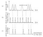
도 2에서 보여지는 바와 같이 신호 처리기(150)로 부터 구동 전원선(111)을 통해 전달되는 전류나 전압으로 파장가변필터(110)를 구동하여 측정하고자 하는 파장 영역에 대해서 스캔하면서 나오는 광신호(a)가 광파장 채널 표준기(140) 내에 있는 후술될 광 필터(141)의 투과 특성(b)과 일치할 때 내장된 광검출기(142)에서 반응하는 전류 신호(c)가 신호처리기(150)에 전달되어, 신호처리기(150)가 이 파장에 대한 표준 파장값을 보여주게 된다.As shown in FIG. 2, the optical signal that is generated while scanning the wavelength range to be measured by driving the wavelength
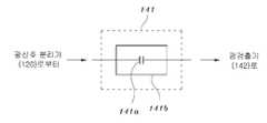
도 3은 상기 광파장 채널 표준기(140)의 상세 구성을 나타낸 것으로, 광파장 채널 표준기(140)가 광필터(141)와 광검출기(142)로 구성된 실시예이다.3 shows a detailed configuration of the optical
이는 상기 광신호 분리기(120)에서 분리된 광신호가 광필터(141)를 통해 광검출기(142)에 입력되도록 된 구조로, 상기 광필터(141)는 정해진 규격에 따라 일정한 파장(또는 주파수) 간격으로 광신호 분리기(120)에서 입력되는 광신호를 투과시키며, 상기 광필터(141)로부터 출력된 광신호는 광검출기(141)에 의해 해당 전기적 신호로 검출되어 신호 처리기(150)로 입력된다.The optical signal separated by the
이에 따라 상기 신호 처리기(150)는 도 1에서와 같이 일정한 주파수 간격의 광신호에 대한 전기적인 출력 특성 즉, 일정하게 파장다중화된 광신호의 각 개별 채널 파장을 측정할 수 있게 된다.Accordingly, as shown in FIG. 1, the
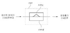
도 4는 상기 광필터(141)의 상세 구성을 나타낸 것으로, 광필터(141)가 페브리-페롯(Febry-Perot)형 광간섭계(141a)로 구성되고, 온도 및 진동 안정화 수단 (141b)이 함께 집적화된 구조이다.4 shows a detailed configuration of the
상기 페브리-페롯형 광간섭계(141a)의 두께와 굴절률 및 광간섭계의 양 단면의 거울 면의 반사률은 측정하고자 하는 파장분할다중 광통신 신호의 파장 영역과 파장 간격에 맞고 투과선폭의 광 투과 특성을 갖는 고정된 크기의 전형적인 페브리-페롯형 광필터 구조로 구성될 수 있다. 특히, 상기 페브리-페롯형 광간섭계(141a)는 외부 온도의 변화나 진동으로 투과 파장 특성이 변화하지 않도록 열적 및 진동으로부터 안정화시킬 수 있는 온도 및 진동 안정화 수단(141b)으로 패키징을 하거나 또는 전기적으로 일정한 온도로 제어가 가능한 온도 제어 기구 등을 사용하여 안정화시키게 된다.The thickness and refractive index of the Fabry-Perot type
도 5는 상기 광필터(141)가 마하젠더(Mach-Zehnder) 광간섭계(141c)로 구성되고, 온도 및 진동 안정화 수단(141d)이 함께 집적화된 구조이다.5 is a structure in which the
상기 마하젠더 광간섭계(141c)는 두 팔의 길이의 차이와 양끝에 있는 광 커플러들의 커플링 효율은 측정하고자 하는 파장분할다중 광통신 신호의 파장 간격과 광 투과 효율에 따라 고정된 크기의 전형적인 마하젠더형 광필터 구조로 구성되어지며, 이러한 마하젠더 광간섭계(141c)는 광섬유형 소자로 구성될 수 있으며, 폴리머나 실리카 등으로 된 평면광도파로 소자로 구성될 수 있다.The Mach-Zehn
특히, 마하젠더 광간섭계(141c)는 상기 페브리-페롯형 광간섭계(141a)와 마찬가지로 외부 온도의 변화나 진동으로 투과 파장 특성이 변화하지 않도록 열적 및 진동으로부터 안정화시킬 수 있은 온도 및 진동 안정화 수단(141d)으로 패키징을 하거나 또는 전기적으로 일정한 온도로 제어가 가능한 온도 제어 기구 등을 사용하여 안정화시키게 된다.In particular, the Mach-Zehnder
도 6은 상기 광파장 채널 표준기(140)의 다른 실시 예를 나타낸 것이다.6 illustrates another embodiment of the optical
이는 상기 광신호 분리기(120)에서 분리된 광신호가 광신호 분리기(143)에서 2개의 경로로 분리되어 각각 광필터(144)와 파장 표준 흡수셀(146)를 통해 광검출기(145),(147)로 입력되어 해당 전기적 신호가 검출되어 신호 처리기(148)로 입력되도록 된 구조로 되어 있다.This means that the optical signal separated by the
여기서, 상기 광필터(144)는 상기 도 4 및 도 5와 같은 구조의 광필터가 사용될 수 있다.In this case, the
상기 파장 표준 흡수셀(146)은 일산화탄소(12C16O,13C16O), 아세틸렌(12C2H2), 시안화수소(H13C14N) 등과 같은 분자 가스 흡수셀 등이 이용될 수 있다.The wavelength
이와 같이 구성된 광파장 채널 표준기(140)에 상기 광신호 분리기(120)로부터 분리되어 입력되는 광신호는 광신호 분리기(143)를 통해 재차 2개의 경로로 나뉘어 각각 광필터(144)와 파장 표준 흡수셀(146)로 입력된다.The optical signal separated from the
상기 광필터(144)는 일정한 파장 또는 주파수 간격을 가진 광 투과 특성을 가진 필터로서 광필터(144)를 통과한 광신호는 광검출기(145)를 통해 전기적 신호로 검출되어 신호 처리기(148)로 입력된다.The
또한, 상기 광신호 분리기(143)로부터 파장 표준 흡수셀(146)로 입력된 광신 호는 파장 표준 흡수셀(146)을 통해 광검출기(147)로 입력되어 해당 전기적 신호로 검출되어 신호 처리기(148)로 입력된다.In addition, the optical signal inputted from the
이에 따라 상기 신호 처리기(148)는 광검출기(145),(147)로부터 입력되는 전기적 신호를 비교 분석하면서 도 7에 나타낸 바와 같이 신호 처리기(150)로 부터 구동 전원선(111)을 통해 전달되는 전류나 전압으로 파장가변필터(110)를 구동하여 측정하고자 하는 파장 영역에 대해서 스캔하면서 나오는 광신호(a)가 광파장 채널 표준기(140) 내에 있는 광 필터(144)의 투과 특성(b)과 일치할 때 내장된 광검출기(145)에서 반응하는 전류 신호(c)가 신호처리기(150)에 전달되어, 신호처리기(150)가 이 파장에 대한 표준 파장값을 보여주게 된다. 아울러 파장 표준 흡수셀(146)을 통과한 광신호(d) 가운데 흡수가 일어나는 특정 표준 파장대의 신호를 비교하여 절대 파장값에 대한 입력 광신호의 파장 표준값을 제공하게 된다.Accordingly, the
도 8은 본 발명의 파장 채널 측정기의 파장 특성을 조정할 수 있도록 한 구조로, 도 1의 광신호 입력 부분에 절대 파장치를 가진 표준 광원에서 출력되는 광신호를 스위치를 이용하여 스위칭할 수 있도록 된 구조로 되어 있다.8 is a structure for adjusting the wavelength characteristics of the wavelength channel meter of the present invention, a structure that can switch the optical signal output from the standard light source having an absolute wavelength value in the optical signal input portion of Figure 1 using a switch It is.
즉, 절대 파장치를 가진 표준 광원(150)과 이 표준 광원(150)에서 출력되는 광신호를 스위칭하기 위한 광 스위치(160)가 도 1의 광신호 입력단에 추가 구성된 구조로, 표준 광원(150)은 파장 표준 흡수셀로 파장 안정화 및 표준화가 이루어진 광원을 사용할 수 있으며, 또한 광 스위치(160)는 전기광학(Electro-Optic) 광 스위치, 열광학(Thermo-Optic) 광 스위치, 전기 역학(Electro-Mechanical) 광 스위 치, 역학(Mechanical) 광 스위치 등이 사용될 수 있다.That is, the standard
이러한 실시 예는 상기 광 스위치(160)를 이용하여 표준 광원(150)으로부터 제공되는 광신호와 측정하고자 하는 광신호를 필요에 따라 스위칭하여 측정파장 특성을 조정할 수 있게 된다. 때로는 입력 광신호의 특성에 따라 도 6의 파장 표준 흡수셀(146)을 이용한 파장 표준 절차가 곤란할 경우에는 별도의 표준 광원을 도 6에 대한 입력 광신호 대신에 사용하던지 아니면 도 8의 경우와 같은 구도를 이용하여 표준화 하는 방법이 필요하다.In this embodiment, by using the
도 9은 본 발명의 다른 실시 예로, 빠른 파장 채널 스캔을 위해 광대역 가변필터로 먼저 측정기의 파장 영역 내에서 광신호가 있는 지를 확인하고, 광신호가 있는 파장 대역에 대해서는 정밀한 파장가변필터로 파장을 분석하면서 세부적인 파장 특성을 측정할 수 있도록 한 실시 예 이다.9 is another embodiment of the present invention, in order to quickly scan a wavelength channel, the broadband variable filter first checks whether there is an optical signal in the wavelength region of the measuring instrument, and analyzes the wavelength with a precise wavelength variable filter for the wavelength band in which the optical signal is present. It is an embodiment to measure the detailed wavelength characteristics.
이는 상기 도 1의 실시 예에 비해 피측정 대상 광신호에 대한 넓은 파장 영역 스캔을 지원하는 광대역 가변필터(Coarse Tunable Filter)(210), 광신호 분리기(220) 및 광검출기(230)가 더 포함되어 구성되고, 도 1의 파장가변필터(110)가 정밀가변필터(Fine Tunable Filter)(240)로 구성된 실시 예로, 도면부호(211),(241)은 각각 필터(210),(240)를 구동하기 위한 전원선이다.Compared to the embodiment of FIG. 1, a wideband
또한, 상기 광대역 가변필터(210) 및 정밀가변필터(240)는 상기 실시 예와 마찬가지로 전기광학(Electro-Optic) 파장가변 광필터, 열광학(Thermo-Optic) 파장가변 광필터, 전기역학(Electro-Mechanical) 파장가변 광필터, 음향광학(Acousto- Optic) 파장가변 광필터 등이 사용될 수 있으며, 광신호 분리기(220),(250)는 광섬유 커플러나 빔 분파기 등이 사용될 수 있다.In addition, the wideband
이와 같은 구성의 본 발명의 다른 실시 예는 입력되는 광신호가 광대역 가변필터(210)를 통해 1차적으로 필터링 된 후, 광신호 분리기(220)를 통해 2개의 경로로 분리되어 광검출기(230) 및 정밀가변필터(240)로 각각 입력된다.According to another exemplary embodiment of the present invention having the above configuration, after the input optical signal is first filtered through the wideband
상기 광검출기(230)로 입력된 광신호는 광검출기(230)를 통해 입력된 광신호에 대한 해당 전기적 신호로 검출되어 신호 처리기(280)로 입력되며, 신호 처리기(280)는 이를 바탕으로 넓은 파장 대역에서의 입력 광신호의 파장 분포와 출력 특성을 측정하게 된다.The optical signal input to the
또한, 입력 광신호가 존재하는 파장 대역에 대해서 세부적인 정밀 파장 분포 특성을 측정하기 위해 상기 광신호 분리기(220)로부터 정밀가변필터(240)로 입력된 광신호는 정밀가변필터(240)에서 필터링 된 후, 광신호 분리기(250)를 통해 재차 분리되어 광검출기(260) 및 광파장 채널 표준기(270)로 입력된다.In addition, the optical signal inputted from the
상기 광검출기(260)로 입력된 광신호는 광검출기(260)를 통해 해당 전기적 신호가 검출되어 신호 처리기(280)로 입력되어 입력 광신호가 존재하는 파장 대역에 대해서 세부적인 정밀 파장 분포 특성을 측정할 수 있도록 된다.The optical signal input to the
또한, 그 규격에 따라 일정한 주파수 간격의 광신호에 대해서 전기적인 출력 특성을 보이는 특성을 갖는 광파장 채널 표준기(270)로 입력된 광신호는 파장 채널 표준기(270)를 통해 신호 처리기(280)로 입력되어 정해진 파장 규격에 맞는 채널의 존재를 파악할 수 있도록 된다.In addition, an optical signal input to the optical
도 10은 도 9의 정밀파장가변 필터(240)의 한 실시 예로서, 입력 광신호는 광서큘레이터(243)을 통해 가변형 광 브레그 회절격자(244, 245, 246,...)에 의해 반사되는 광신호로 정밀 파장 분포 특성이 측정되어지게 한다. 가변형 광 브레그 회절격자(244, 245, 246,...)는 각각 파장 영역이 다른 필터로 구성되고 열광학 또는 압전 효과에 의한 인장에 의해 파장 가변성을 갖는 구조의 필터가 사용된다. 가변형 광 브레그 회절격자(244, 245, 246,...)의 전기적 구동에 필요한 구동 전원선(242)은 구동 전원선(241)과 호환이 되기 위해 리본 전선 커넥터로 구성되거나 또는 각 가변형 광 브레그 회절격자(244, 245, 246,...)로 구동 전기 신호를 보낼 수 있는 스위치가 내장된 전기 단자가 달린 수단으로 구성된다.FIG. 10 illustrates an example of the precision wavelength
도 11은 본 발명의 또 다른 실시 예로, 측정하고자 하는 광신호의 빠른 측정을 위해 입력되는 피측정 대상 광신호의 존재여부를 먼저 판단한 다음, 피측정 대상 광신호의 파장분호와 출력을 측정하기 위한 실시 예이다.11 is another embodiment of the present invention. First, it is first determined whether an optical signal to be measured is input for fast measurement of an optical signal to be measured, and then the wavelength encoding and output of the optical signal to be measured are measured. Example.
이는 상기 도 1의 실시 예에 비해 입력되는 피측정 대상 광신호의 존재여부를 검출하기 위한 광신호 분리기(310) 및 광검출기(320)를 더 포함하게 되며, 상기 광신호 분리기(310)는 광섬유 커플러나 빔 분파기 등이 사용될 수 있다.This further includes an
이러한 실시 예에서 입력되는 광신호는 광신호 분리기(310)를 통해 2개의 경로로 각각 분리되어 광검출기(320) 및 파장가변필터(330)로 입력된다.In this embodiment, the optical signal input is separated into two paths through the
상기 광검출기(320)로 입력된 광신호는 광검출기(320)를 통해 전기적 신호로 검출되어 신호 처리기(370)로 입력되며, 신호 처리기(370)는 이를 바탕으로 입력되는 광신호의 존재여부를 판단하게 된다.The optical signal input to the
또한, 상기 파장가변필터(330)로 입력된 광신호는 파장가변필터(330)를 통해 필터링된 후, 광신호 분리기(340)에서 2개의 경로로 분리된다.In addition, the optical signal input to the wavelength
상기 광신호 분리기(340)에서 분리된 하나의 광신호는 광검출기(350)를 통해 전기적 신호로 검출되어 신호 처리기(370)로 입력되며, 신호 처리기(370)는 이를 바탕으로 피측정 광신호에 대한 파장분포와 출력을 측정할 수 있게 된다.One optical signal separated from the
상기 광신호 분리기(340)에서 분리된 다른 하나의 광신호는 광파장 채널 표준기(360)를 통해 신호 처리기(370)로 입력되며, 신호 처리기(370)는 이를 바탕으로 일정한 주파수 간격의 광신호에 대한 전기적인 출력 특성 즉, 일정하게 파장다중화된 광신호의 각 개별 채널 파장을 확인할 수 있게 된다.The other optical signal separated from the
도 12는 상기 각 실시 예에서 신호 처리기(150),(280),(370)의 출력을 표시할 수 있는 표시기 들을 나타낸 것으로, 파워 표시기(410), 파장 채널 확인기(420), 광신호 파장 분포 표시기(430) 등을 포함하며, 이들은 신호 처리기(150),(280),(370)의 각 출력을 순차적으로나 동시에 또는 개별적으로 표시할 수 있게 된다.FIG. 12 shows indicators capable of displaying the outputs of the
상술한 바와 같이, 본 발명의 바람직한 실시예를 참조하여 설명하였지만, 해당 기술 분야의 숙련된 당업자는 하기의 특허청구범위에 기재된 본 발명의 사상 및 영역으로부터 벗어나지 않는 범위내에서 본 발명을 다양하게 수정 또는 변경하여 실시할 수 있다.As described above, although described with reference to a preferred embodiment of the present invention, those skilled in the art various modifications of the present invention without departing from the spirit and scope of the invention described in the claims below Or it can be changed.
이상에서 살펴본 바와 같이, 본 발명에 따른 광신호 파장 채널 측정기는 광통신기술의 국제규격에 맞는 파장 채널 간격의 광원신호 및 광소자의 파장 특성을 측정함과 동시에 출력 및 스펙트럼을 확인할 수 있으며, 저가형 휴대용 기기로 구성하기 용이함에 따라 향후 다가올 광가입자망 시대에 큰 활용성을 기대할 수 있다.As described above, the optical signal wavelength channel measuring device according to the present invention can measure the wavelength characteristics of the light source signal and the optical element of the wavelength channel interval in accordance with the international standard of optical communication technology and at the same time can check the output and spectrum, low-cost portable device As it is easy to configure, it can be expected to have great utility in the coming optical subscriber network era.
Claims (22)
Translated fromKoreanPriority Applications (1)
| Application Number | Priority Date | Filing Date | Title |
|---|---|---|---|
| KR1020050026076AKR100585293B1 (en) | 2005-03-29 | 2005-03-29 | Optical Signal Wavelength Channel Meter |
Applications Claiming Priority (1)
| Application Number | Priority Date | Filing Date | Title |
|---|---|---|---|
| KR1020050026076AKR100585293B1 (en) | 2005-03-29 | 2005-03-29 | Optical Signal Wavelength Channel Meter |
Publications (1)
| Publication Number | Publication Date |
|---|---|
| KR100585293B1true KR100585293B1 (en) | 2006-06-02 |
Family
ID=37182189
Family Applications (1)
| Application Number | Title | Priority Date | Filing Date |
|---|---|---|---|
| KR1020050026076AExpired - Fee RelatedKR100585293B1 (en) | 2005-03-29 | 2005-03-29 | Optical Signal Wavelength Channel Meter |
Country Status (1)
| Country | Link |
|---|---|
| KR (1) | KR100585293B1 (en) |
Cited By (4)
| Publication number | Priority date | Publication date | Assignee | Title |
|---|---|---|---|---|
| WO2011046378A3 (en)* | 2009-10-15 | 2011-09-15 | 오큐브 주식회사 | Wavelength detector and an optical coherence tomography device having the same |
| KR101131954B1 (en) | 2009-10-15 | 2012-03-29 | 이큐메드 주식회사 | Wavelength detector and optical coherence topography having the same |
| KR20180135166A (en) | 2017-06-12 | 2018-12-20 | 대구도시철도공사 | Comparison test method of measurement devices |
| US20240364426A1 (en)* | 2023-04-28 | 2024-10-31 | Nokia Solutions And Networks Oy | Coherent optical receiver with tunable local oscillator |
Citations (4)
| Publication number | Priority date | Publication date | Assignee | Title |
|---|---|---|---|---|
| JPH06222215A (en)* | 1992-10-07 | 1994-08-12 | Oki Electric Ind Co Ltd | Light wave length filter device |
| KR19990024761A (en)* | 1997-09-08 | 1999-04-06 | 정선종 | Inter-channel delay compensation multiwavelength channel transmission optical filter |
| KR20010056290A (en)* | 1999-12-14 | 2001-07-04 | 오길록 | Dynamic Gain Control of Booster Amplifier in WDM Transmission Systems |
| US20030043471A1 (en) | 2001-08-29 | 2003-03-06 | Belser Karl Arnold | Free-space dynamic wavelength routing systems with interleaved channels for enhanced performance |
- 2005
- 2005-03-29KRKR1020050026076Apatent/KR100585293B1/ennot_activeExpired - Fee Related
Patent Citations (4)
| Publication number | Priority date | Publication date | Assignee | Title |
|---|---|---|---|---|
| JPH06222215A (en)* | 1992-10-07 | 1994-08-12 | Oki Electric Ind Co Ltd | Light wave length filter device |
| KR19990024761A (en)* | 1997-09-08 | 1999-04-06 | 정선종 | Inter-channel delay compensation multiwavelength channel transmission optical filter |
| KR20010056290A (en)* | 1999-12-14 | 2001-07-04 | 오길록 | Dynamic Gain Control of Booster Amplifier in WDM Transmission Systems |
| US20030043471A1 (en) | 2001-08-29 | 2003-03-06 | Belser Karl Arnold | Free-space dynamic wavelength routing systems with interleaved channels for enhanced performance |
Cited By (4)
| Publication number | Priority date | Publication date | Assignee | Title |
|---|---|---|---|---|
| WO2011046378A3 (en)* | 2009-10-15 | 2011-09-15 | 오큐브 주식회사 | Wavelength detector and an optical coherence tomography device having the same |
| KR101131954B1 (en) | 2009-10-15 | 2012-03-29 | 이큐메드 주식회사 | Wavelength detector and optical coherence topography having the same |
| KR20180135166A (en) | 2017-06-12 | 2018-12-20 | 대구도시철도공사 | Comparison test method of measurement devices |
| US20240364426A1 (en)* | 2023-04-28 | 2024-10-31 | Nokia Solutions And Networks Oy | Coherent optical receiver with tunable local oscillator |
Similar Documents
| Publication | Publication Date | Title |
|---|---|---|
| US7426038B2 (en) | Detection device, optical path length measurement device, measurement instrument, optical member evaluation method, and temperature change detection method | |
| Slavík et al. | High-performance all-fiber Fabry-Perot filters with superimposed chirped Bragg gratings | |
| JP2009506342A (en) | Fiber PMD evaluation method using POTDR trace | |
| EP1133083B1 (en) | In-line polarization monitoring and control in lightwave communication systems | |
| US12068779B2 (en) | Fibre-optic measurement system, method of adaptation of the communication optical fibre into a measurement system, and fibre-optic measurement and communication system | |
| US6961128B2 (en) | Apparatus for detecting cross-talk and method therefor | |
| KR100585293B1 (en) | Optical Signal Wavelength Channel Meter | |
| US7167647B2 (en) | Wavelength division multiplexing optical performance monitors | |
| Ding et al. | Multi‐Object Silicon Photonic Spectrometer | |
| US6671434B2 (en) | Optical performance monitor | |
| US11781888B2 (en) | Reflected light wavelength scanning device including silicon photonics interrogator | |
| Rajan et al. | Effect of polarisation-dependent loss on the performance accuracy of a ratiometric wavelength measurement system | |
| JPH0953999A (en) | Optical external force detector | |
| Li et al. | Performance characteristics of a WDM channel monitor based on an all-fiber AOTF with an on-fiber photodetector | |
| US20210296848A1 (en) | Laser diagnostics apparatus | |
| JPWO2020261207A5 (en) | ||
| Morrone et al. | Simple method to measure the fiber optic nonlinear coefficient using a Sagnac interferometer | |
| KR100343070B1 (en) | System and method for real time wavelength watching of each chahnnels in wavelength division multiplexing optical transmission system | |
| Kaczmarek | Fiber optic Sagnac loop with a polarization maintaining photonic crystal fiber as an optical wavelength demodulator for fiber Bragg grating sensors | |
| Mutugala | Optoelectronic oscillators with hollow-core fibres | |
| HK40072468A (en) | Fibre-optic measurement system, method of adaptation of the communication optical fibre into a measurement system, and fibre-optic measurement and communication system | |
| Yang et al. | Simultaneous channel and OSNR monitoring using a polarization-selective modulator and an LED | |
| CN116865854A (en) | Wavelength detection device capable of being integrated on photon integrated chip | |
| Tissot et al. | Low loss wavelength monitor with sub-picometer resolution based on tilted fiber gratings | |
| JP2005195474A (en) | Multiple-wavelength batch monitoring method and device |
Legal Events
| Date | Code | Title | Description |
|---|---|---|---|
| A201 | Request for examination | ||
| PA0109 | Patent application | St.27 status event code:A-0-1-A10-A12-nap-PA0109 | |
| PA0201 | Request for examination | St.27 status event code:A-1-2-D10-D11-exm-PA0201 | |
| D13-X000 | Search requested | St.27 status event code:A-1-2-D10-D13-srh-X000 | |
| D14-X000 | Search report completed | St.27 status event code:A-1-2-D10-D14-srh-X000 | |
| E701 | Decision to grant or registration of patent right | ||
| PE0701 | Decision of registration | St.27 status event code:A-1-2-D10-D22-exm-PE0701 | |
| GRNT | Written decision to grant | ||
| PR0701 | Registration of establishment | St.27 status event code:A-2-4-F10-F11-exm-PR0701 | |
| PR1002 | Payment of registration fee | Fee payment year number:1 St.27 status event code:A-2-2-U10-U11-oth-PR1002 | |
| PG1601 | Publication of registration | St.27 status event code:A-4-4-Q10-Q13-nap-PG1601 | |
| PN2301 | Change of applicant | St.27 status event code:A-5-5-R10-R11-asn-PN2301 St.27 status event code:A-5-5-R10-R13-asn-PN2301 | |
| R18-X000 | Changes to party contact information recorded | St.27 status event code:A-5-5-R10-R18-oth-X000 | |
| PR1001 | Payment of annual fee | Fee payment year number:4 St.27 status event code:A-4-4-U10-U11-oth-PR1001 | |
| R18-X000 | Changes to party contact information recorded | St.27 status event code:A-5-5-R10-R18-oth-X000 | |
| PN2301 | Change of applicant | St.27 status event code:A-5-5-R10-R11-asn-PN2301 | |
| PN2301 | Change of applicant | St.27 status event code:A-5-5-R10-R11-asn-PN2301 | |
| PR1001 | Payment of annual fee | Fee payment year number:5 Fee payment year number:6 St.27 status event code:A-4-4-U10-U11-oth-PR1001 | |
| PN2301 | Change of applicant | St.27 status event code:A-5-5-R10-R11-asn-PN2301 | |
| PN2301 | Change of applicant | St.27 status event code:A-5-5-R10-R11-asn-PN2301 | |
| PN2301 | Change of applicant | St.27 status event code:A-5-5-R10-R14-asn-PN2301 | |
| PN2301 | Change of applicant | St.27 status event code:A-5-5-R10-R11-asn-PN2301 | |
| PN2301 | Change of applicant | St.27 status event code:A-5-5-R10-R14-asn-PN2301 | |
| PR1001 | Payment of annual fee | Fee payment year number:7 St.27 status event code:A-4-4-U10-U11-oth-PR1001 | |
| FPAY | Annual fee payment | Payment date:20121227 Year of fee payment:8 | |
| PR1001 | Payment of annual fee | Fee payment year number:8 St.27 status event code:A-4-4-U10-U11-oth-PR1001 | |
| P22-X000 | Classification modified | St.27 status event code:A-4-4-P10-P22-nap-X000 | |
| FPAY | Annual fee payment | Payment date:20131120 Year of fee payment:9 | |
| PR1001 | Payment of annual fee | Fee payment year number:9 St.27 status event code:A-4-4-U10-U11-oth-PR1001 | |
| FPAY | Annual fee payment | Payment date:20141216 Year of fee payment:10 | |
| PR1001 | Payment of annual fee | Fee payment year number:10 St.27 status event code:A-4-4-U10-U11-oth-PR1001 | |
| PN2301 | Change of applicant | St.27 status event code:A-5-5-R10-R11-asn-PN2301 St.27 status event code:A-5-5-R10-R13-asn-PN2301 | |
| LAPS | Lapse due to unpaid annual fee | ||
| PC1903 | Unpaid annual fee | Not in force date:20160525 Payment event data comment text:Termination Category : DEFAULT_OF_REGISTRATION_FEE St.27 status event code:A-4-4-U10-U13-oth-PC1903 | |
| PN2301 | Change of applicant | St.27 status event code:A-5-5-R10-R11-asn-PN2301 St.27 status event code:A-5-5-R10-R13-asn-PN2301 | |
| P22-X000 | Classification modified | St.27 status event code:A-4-4-P10-P22-nap-X000 | |
| PC1903 | Unpaid annual fee | Ip right cessation event data comment text:Termination Category : DEFAULT_OF_REGISTRATION_FEE Not in force date:20160525 St.27 status event code:N-4-6-H10-H13-oth-PC1903 | |
| R18-X000 | Changes to party contact information recorded | St.27 status event code:A-5-5-R10-R18-oth-X000 | |
| P22-X000 | Classification modified | St.27 status event code:A-4-4-P10-P22-nap-X000 | |
| R18-X000 | Changes to party contact information recorded | St.27 status event code:A-5-5-R10-R18-oth-X000 | |
| R18-X000 | Changes to party contact information recorded | St.27 status event code:A-5-5-R10-R18-oth-X000 |