KR100584427B1 - Fuel injection valve - Google Patents
Fuel injection valveDownload PDFInfo
- Publication number
- KR100584427B1 KR100584427B1KR1020040039439AKR20040039439AKR100584427B1KR 100584427 B1KR100584427 B1KR 100584427B1KR 1020040039439 AKR1020040039439 AKR 1020040039439AKR 20040039439 AKR20040039439 AKR 20040039439AKR 100584427 B1KR100584427 B1KR 100584427B1
- Authority
- KR
- South Korea
- Prior art keywords
- iron core
- yoke
- fuel injection
- movable iron
- magnetic
- Prior art date
- Legal status (The legal status is an assumption and is not a legal conclusion. Google has not performed a legal analysis and makes no representation as to the accuracy of the status listed.)
- Expired - Fee Related
Links
Images


Classifications
- F—MECHANICAL ENGINEERING; LIGHTING; HEATING; WEAPONS; BLASTING
- F02—COMBUSTION ENGINES; HOT-GAS OR COMBUSTION-PRODUCT ENGINE PLANTS
- F02M—SUPPLYING COMBUSTION ENGINES IN GENERAL WITH COMBUSTIBLE MIXTURES OR CONSTITUENTS THEREOF
- F02M61/00—Fuel-injectors not provided for in groups F02M39/00 - F02M57/00 or F02M67/00
- F02M61/04—Fuel-injectors not provided for in groups F02M39/00 - F02M57/00 or F02M67/00 having valves, e.g. having a plurality of valves in series
- F02M61/10—Other injectors with elongated valve bodies, i.e. of needle-valve type
- F—MECHANICAL ENGINEERING; LIGHTING; HEATING; WEAPONS; BLASTING
- F02—COMBUSTION ENGINES; HOT-GAS OR COMBUSTION-PRODUCT ENGINE PLANTS
- F02M—SUPPLYING COMBUSTION ENGINES IN GENERAL WITH COMBUSTIBLE MIXTURES OR CONSTITUENTS THEREOF
- F02M51/00—Fuel-injection apparatus characterised by being operated electrically
- F02M51/06—Injectors peculiar thereto with means directly operating the valve needle
- F02M51/061—Injectors peculiar thereto with means directly operating the valve needle using electromagnetic operating means
- F02M51/0625—Injectors peculiar thereto with means directly operating the valve needle using electromagnetic operating means characterised by arrangement of mobile armatures
- F02M51/0664—Injectors peculiar thereto with means directly operating the valve needle using electromagnetic operating means characterised by arrangement of mobile armatures having a cylindrically or partly cylindrically shaped armature, e.g. entering the winding; having a plate-shaped or undulated armature entering the winding
- F02M51/0671—Injectors peculiar thereto with means directly operating the valve needle using electromagnetic operating means characterised by arrangement of mobile armatures having a cylindrically or partly cylindrically shaped armature, e.g. entering the winding; having a plate-shaped or undulated armature entering the winding the armature having an elongated valve body attached thereto
Landscapes
- Engineering & Computer Science (AREA)
- Chemical & Material Sciences (AREA)
- Combustion & Propulsion (AREA)
- Mechanical Engineering (AREA)
- General Engineering & Computer Science (AREA)
- Physics & Mathematics (AREA)
- Electromagnetism (AREA)
- Fuel-Injection Apparatus (AREA)
Abstract
Translated fromKoreanDescription
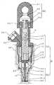
Translated fromKorean도 1은 실시예 1에 의한 연료 분사 밸브의 전체 구성을 도시한 종단면도.1 is a longitudinal sectional view showing the entire configuration of a fuel injection valve according to the first embodiment;
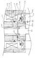
도 2는 실시예 1에 의한 연료 분사 밸브의 주요부의 구성을 설명하기 위한 부분 확대도.2 is a partially enlarged view for explaining the configuration of main parts of a fuel injection valve according to the first embodiment.
도 3은 실시예 1에 의한 연료 분사 밸브의 분사량 특성을 도시한 도면.3 is a view showing injection quantity characteristics of a fuel injection valve according to the first embodiment;
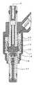
도 4는 실시예 2에 의한 연료 분사 밸브의 주요부의 구성을 설명하기 위한 부분 확대도.4 is a partially enlarged view for explaining the configuration of main parts of a fuel injection valve according to the second embodiment;
도 5는 실시예 2에 의한 연료 분사 밸브의 효과를 설명하기 위한 도면.5 is a view for explaining the effect of a fuel injection valve according to the second embodiment;
도 6은 종래의 연료 분사 밸브의 전체 구성을 도시한 종단면도.6 is a longitudinal sectional view showing an entire structure of a conventional fuel injection valve.
도 7은 종래의 연료 분사 밸브의 주요부의 구성을 설명하기 위한 부분 확대도.7 is a partially enlarged view for explaining the structure of a main part of a conventional fuel injection valve.
도 8은 요크에 사용되는 전자 스테인리스의 온도와 자속 밀도의 관계를 도시한 도면.8 is a diagram showing a relationship between temperature and magnetic flux density of an electronic stainless steel used in a yoke.
도 9는 종래의 연료 분사 밸브의 분사량 특성의 제품 편차를 도시한 도면.9 is a view showing product variation of injection quantity characteristics of a conventional fuel injection valve.
<부호의 설명><Description of the code>
1 : 연료 분사 밸브30 : 솔레노이드 장치1
11 : 고정 철심12 : 하우징11: fixed iron core 12: housing
13 : 코일14 : 압축 스프링13: coil 14: compression spring
15 : 로드16 : 요크15: Load 16: York
16a : 자기 특성 변화 부분17 : 슬리브16a: magnetic property change part 17: sleeve
17a : 용접부17b : 용접부17a: welded portion 17b: welded portion
20 : 밸브 장치21 : 밸브체20: valve device 21: valve body
21a : 밸브 시트부22 : 가동 철심21a: valve seat portion 22: movable iron core
22a : 가동 철심의 오목부23 : 플레이트22a: recess of movable core 23: plate
24 : 밸브 본체30 : 연료 공급관24: valve body 30: fuel supply pipe
31 : 연료 유통 구멍32 : 접속부31: fuel distribution hole 32: connection portion
33 : 필터의 메시부34 : 필터 지지 부재33: mesh portion of the filter 34: filter support member
40 : 실린더 헤드51 : 실 재40: cylinder head 51: real
52 : 실 재53 : 와셔52: Actual 53: Washer
54 : 커넥터부55 : 터미널54 connector 55 terminal
61 : 스러스트 에어 갭62 : 레이디얼 에어 갭61
100 : 자력선100: magnetic force line
기술분야Technical Field
본 발명은 주로 차량용 엔진에 사용하는 연료 분사 밸브에 관한 것이다.TECHNICAL FIELD This invention relates to the fuel injection valve mainly used for a vehicle engine.
종래기술Prior art
도 6은 예를 들면, 특허 문헌 1(특개2002-3831호 공보)에 나타내여진 종래의 연료 분사 밸브의 전체 구성을 도시한 종단면도이다.FIG. 6 is a longitudinal sectional view showing the overall configuration of a conventional fuel injection valve shown in, for example, Patent Document 1 (Patent No. 2002-3831).
또한, 도 7은 도 6에 도시한 연료 분사 밸브의 주요부(자기 통로 부분)의 구성을 설명하기 위한 부분 확대도이다. 또한, 도 7에서는 단면을 나타내는 해칭은 생략하고 있다.7 is a partially enlarged view for demonstrating the structure of the principal part (magnetic path part) of the fuel injection valve shown in FIG. In addition, hatching which shows a cross section is abbreviate | omitted in FIG.
엔진의 마이크로컴퓨터로부터 연료 분사 밸브의 구동 회로(도시 생략)에 동작 신호가 보내지면, 코일(13)에 전류가 흐르고, 고정 철심(11), 가동 철심(22), 요크(16), 하우징(12)으로 구성되는 자기 루프에 자력선(100)으로 도시한 자속이 생기고, 가동 철심(22)은 압축 스프링(14)의 스프링력을 초과하는 전자 흡인력을 받아서 고정 철심(11)측으로 흡인된다.When an operation signal is sent from the microcomputer of the engine to the drive circuit (not shown) of the fuel injection valve, a current flows in the
가동 철심(22)이 고정 철심(11)측으로 흡인됨에 의해, 가동 철심과 일체화된 밸브체(21)도 고정 철심(11)측으로 이동하고, 엔진 내로의 연료 분사가 행하여진다.When the
도 6 또는 도 7에 있어서, 17은 요크(16)와 고정 철심(11)을 접속하기 위한 접속부재인 비자성의 금속성 슬리브이다.In FIG. 6 or 7, 17 is a nonmagnetic metallic sleeve which is a connecting member for connecting the
상기 슬리브(17)는 고정 철심(11)이 끼워들어가는 원통부와, 그 원통부의 요크(16)측의 단부 외주에 링 형상으로 돌출하여 형성된 링 부로서 구성되어 있다. 따라서, 도 7로부터도 분명한 바와 같이, 슬리브(17)의 단면 형상은 L자 모양을 하고 있다.The
그리고, 슬리브(17)의 링 부는 요크(16)와 맞닿은 상태에서 요크(16)와 용접되고, 슬리브(17)의 원통부는 끼워들어간 고정 철심(11)과 용접되어 있다.And the ring part of the
따라서 슬리브(17)를 통하여, 고정 철심(11)과 요크(16)의 위치 관계는 고정된다.Thus, through the
또한, 17a는 슬리브(17)의 링 부와 요크(16)와의 용접부분을 나타내고 있고, 17b는 슬리브(17)의 원통부와 고정 철심(11)과의 용접부분을 나타내고 있다.In addition, 17a has shown the welding part of the ring part of the
이와 같이, 요크(16)와 고정 철심(11)의 사이에 비자성 금속제의 슬리브(17)를 배치하여, 고정 철심(11)과 요크(16)와의 사이의 자기 리크를 극력 적게 하고, 또한, 요크(16)와 슬리브(17) 사이 및 고정 철심(11)과 슬리브(17)를 용접 접합하여 연료의 실링을 행하고 있다.Thus, the
특히, 통내 분사용 연료 분사 밸브(즉, 차량용의 연료 분사 밸브)는 밸브체의 응답성을 고속으로 할 필요가 있기 때문에, 슬리브(17)에 발생하는 와전류를 최소로 할 것이 요구된다.In particular, since the cylinder injection fuel injection valve (that is, the vehicle fuel injection valve) needs to make the responsiveness of the valve body high speed, it is required to minimize the eddy current generated in the
이와 같은 연료 분사 밸브에서는 슬리브(17)의 두께(t)를 극력 얇게 함에 의해, 와전류의 발생을 최소화하고 있다.In such a fuel injection valve, the thickness t of the
[특허 문헌 1][Patent Document 1]
특개2002-3831호 공보(도 1)Japanese Patent Laid-Open No. 2002-3831 (FIG. 1)
종래의 연료 분사 밸브에서는 슬리브(17)의 두께를 얇게 하면, 슬리브(17)와 요크(16)와의 용접부(17a)는 요크(16)의 자기 통로(즉, 자력선(100)의 통로)에 가깝기 때문에, 용접에 의해 고온화하는 부분이 일부 요크의 자기 통로로 확산하고, 그 부분(즉, 도 7의 파선으로 도시한 반원의 내부)은 자속 밀도가 저하하는 자기 특성 변화 부분(16a)으로 된다.In the conventional fuel injection valve, when the thickness of the
연료 분사 밸브에 있어서 주로 요크(16)의 재질이 되는 전자 스테인리스는 도 8에 도시한 바와 같이, 약 900℃ 이상에서 자속 밀도가 급격하게 저하(예를 들면 900℃에서 자속 밀도가 1.10T였던 것이 950℃에서 자속 밀도가 1,02T로 저하)하는 경향이 있고, 가동 철심(22)에 발생하는 전자 흡인력도 저하되어 버린다.As shown in FIG. 8, the magnetic stainless steel, which is mainly made of the
연료 분사 밸브를 다량 생산하는 경우, 용접 온도 및 용접 위치의 편차에 의해 자기 특성 변화 부분의 자기 특성도 흐트러지기 때문에, 가동 철심에 발생하는 전자 흡인력에도 편차가 발생한다.In the case of producing a large amount of fuel injection valves, the magnetic characteristics of the magnetic characteristic change portion are also disturbed due to the deviation of the welding temperature and the welding position, so that the variation also occurs in the electron attraction force generated in the movable iron core.
따라서 생산되는 연료 분사 밸브의 분사량 특성은 제품마다 편차가 매우 커진다는 문제가 있다.Therefore, the injection amount characteristic of the fuel injection valve produced has a problem that the deviation becomes very large for every product.
도 9는 종래의 연료 분사 밸브의 분사량 특성의 제품 편차를 도시한 도면으로서, 횡축은 연료 분사 밸브에 인가하는 분사 신호의 구동 펄스 폭(msec), 종축은 1회당의 연료 분사량(㎣)이다.Fig. 9 is a diagram showing product variation in injection quantity characteristics of a conventional fuel injection valve, wherein the horizontal axis is the drive pulse width (msec) of the injection signal applied to the fuel injection valve, and the vertical axis is the fuel injection amount per stroke.
도 9에 도시한 바와 같이, 종래의 연료 분사 밸브의 분사량 특성의 제품 편차의 상한과 하한에서는 10% 정도의 편차 폭이 있다.As shown in FIG. 9, there exists a deviation width of about 10% in the upper limit and the lower limit of the product deviation of the injection quantity characteristic of the conventional fuel injection valve.
본 발명은 상술한 바와 같은 문제점을 해결하기 위해 이루어진 것으로, 슬리브와 요크와의 용접시의 열에 의해 발생하는 자기 특성 변화 부분에 기인하는 분사량 특성의 제품 편차를 억제할 수 있는 차량용의 연료 분사 밸브를 제공하는 것을 목적으로 한다.SUMMARY OF THE INVENTION The present invention has been made to solve the problems described above, and has a fuel injection valve for a vehicle capable of suppressing product variation in injection quantity characteristics due to a magnetic characteristic change portion generated by heat during welding of a sleeve and a yoke. It aims to provide.
본 발명에 관한 연료 분사 밸브는 연료 분사 신호에 응하여 축방향으로 왕복 이동하는 통형상의 가동 철심, 일단이 상기 가동 철심과 일체화되고, 타단에 밸브 시트부를 마련한 밸브체, 상기 밸브 시트부가 이접함에 의해 개폐되는 오리피스를 갖은 플레이트로 구성된 밸브 장치와, 상기 가동 철심과 축방향으로 대향하여 배치되는 통형상의 고정 철심, 상기 가동 철심의 외주부에 배치되는 통형상의 요크, 용접에 의해 상기 고정 철심과 상기 요크를 접합하여 일체화하는 비자성 금속의 슬리브, 상기 고정 철심, 가동 철심, 요크와 함께 자기 루프를 형성하는 하우징, 상기 고정 철심의 외주부에 배치되고 상기 가동 철심에 축방향의 전자적 흡인력을 부여하는 코일, 상기 밸브체를 상기 플레이트 방향으로 이동시키는 스프링력을 가세하는 압축 스프링으로 구성된 솔레노이드 장치를 구비한 연료 분사 밸브에 있어서, 상기 가동 철심은 상기 슬리브와 상기 요크를 용접할 때의 열에 의해 상기 요크에 생기는 자기 특성 변화 부분과 대향하는 위치에서, 그 외주에 소정 폭과 깊이를 갖는 지름 방향의 오목부가 형성되어 있다.The fuel injection valve according to the present invention has a cylindrical movable iron core which reciprocates in an axial direction in response to a fuel injection signal, one end of which is integrated with the movable iron core, and a valve body provided with a valve seat portion at the other end thereof, by contacting the valve seat portion. A valve device comprising a plate having an orifice to be opened and closed, a cylindrical fixed iron core disposed in an axial direction opposite to the movable iron core, a cylindrical yoke disposed at an outer circumference of the movable iron core, and the fixed iron core and the Sleeves of non-magnetic metal for joining and integrating yokes, housings for forming a magnetic loop together with the fixed iron cores, movable iron cores and yokes, and coils disposed on the outer periphery of the fixed iron cores to impart axial electromagnetic attraction to the movable iron cores. Compression spring for adding a spring force for moving the valve body in the plate direction In the fuel injection valve provided with the solenoid device comprised, the said movable iron core has the predetermined width and depth in the outer periphery at the position which opposes the magnetic characteristic change part which arises in the said yoke by the heat | fever at the time of welding the said sleeve and the said yoke. The radial part which has a radial direction is formed.
본 발명에 의하면, 가동 철심은 상기 슬리브와 상기 요크를 용접할 때의 열에 의해 상기 요크에 생기는 자기 특성 변화 부분과 대향하는 위치에 있어서, 그 외주에 소정 폭과 깊이를 갖는 지름 방향의 오목부가 형성되어 있기 때문에, 가동 철심을 통과하는 자속은 오목부의 하측(즉, 고정 철심이 없는 측)으로 우회한다.According to the present invention, the movable iron core is provided with a radially concave portion having a predetermined width and depth at its outer circumference at a position facing the magnetic characteristic change portion generated in the yoke by heat when welding the sleeve and the yoke. As a result, the magnetic flux passing through the movable iron core is diverted to the lower side of the recess (that is, the side without the fixed iron core).
따라서 요크의 자기 특성 변화 부분을 통과하는 자속 수을 감소시켜서, 자기 특성의 편차에 의한 영향을 받기 어렵게 하는 것이 가능해지고, 슬리브와 요크와의 용접시의 열에 의해 발생하는 자기 특성 변화 부분에 기인하는 분사량 특성의 제품 편차를 억제할 수 있다.Therefore, it is possible to reduce the number of magnetic fluxes passing through the magnetic characteristic change portion of the yoke, making it difficult to be affected by the variation of the magnetic characteristics, and the injection amount due to the magnetic characteristic change portion generated by the heat during welding of the sleeve and the yoke. The product deviation of a characteristic can be suppressed.
실시예 1Example 1
도 1은 실시예 1에 의한 연료 분사 밸브의 전체 구성을 도시한 종단면도이다.1 is a longitudinal sectional view showing the entire configuration of a fuel injection valve according to the first embodiment.
또한, 도 2는 도 1에 도시한 실시예 1에 의한 연료 분사 밸브의 주요부(자기 통로 부분)의 구성을 설명하기 위한 부분 확대도이다. 또한, 도 2에서는 단면을 나타내는 해칭은 생략하고 있다.2 is a partially enlarged view for demonstrating the structure of the main part (magnetic path part) of the fuel injection valve by
도 1에 도시한 바와 같이, 본 실시예에 의한 연료 분사 밸브(1)는 솔레노이드 장치(10)와 밸브 장치(20)로 구성되어 있다.As shown in FIG. 1, the
솔레노이드 장치(10)는 코일(13), 고정 철심(11), 요크(16), 하우징(12), 고정 철심(11)과 요크(16)를 접속하기 위한 접속부재인 비자성 금속제의 슬리브(17), 후술하는 가동 철심과 일체화된 밸브에 스프링력을 가세하기 위한 압축 스프링(14), 압축 스프링(14)의 위치를 조정하고 고정하는 로드(15) 등으로 구성되어 있다.The
또한, 밸브 장치(20)는 밸브체(21), 밸브체(21)를 고정하고 수용하는 밸브 본체(24), 밸브체(21)의 일단과 일체화된 가동 철심(22), 밸브 본체(24)의 단부에 마련된 밸브 시트부(24a), 복수의 오리피스를 갖는 플레이트(23) 등으로 구성되어 있다.In addition, the
30은 연료 분사 밸브(1)에 고압의(예를 들면, 2MPa 이상의)의 연료를 공급하기 위한 연료 공급관이고, 31은 연료 공급관(30)의 연료 유통 구멍이다.30 is a fuel supply pipe for supplying fuel of high pressure (for example, 2 MPa or more) to the
자동차용의 엔진은 복수 기통이기 때문에, 각 기통에 대응하여 복수의 연료 분사 밸브를 지면(紙面)의 전후 방향(지면과 직교하는 방향)으로 배열하고, 연료 공급관(30)의 길이 방향이 지면의 전후 방향(지면과 직교하는 방향)으로 배치된다. 또한, 33는 필터의 메시부, 34는 필터 지지 부재이다.Since the engine for automobiles has a plurality of cylinders, a plurality of fuel injection valves are arranged in the front-rear direction (the direction orthogonal to the ground) of the ground corresponding to each cylinder, and the longitudinal direction of the
연료 분사 밸브(1)는 연료 공급관(30)과 엔진의 실린더 헤드(40)의 사이에 각각 실 재(51 및 52)를 사이에 두고 축방향 하향의 누르는 하중에 의해 와셔(53)상에 부착된다.The
엔진의 마이크로컴퓨터로부터 연료 분사 밸브(1)의 구동 회로(도시 생략)에 동작 신호가 보내지면, 코일(13)에 전류가 흐르고, 고정 철심(11), 가동 철심(22), 요크(16), 하우징(12)으로 구성되는 자기 루프에 자속이 생기고, 가동 철심(22)은 압축 스프링(14)의 스프링력을 초과하는 전자 흡인력을 받아서 고정 철심(11)측으로 흡인된다.When an operation signal is sent from the microcomputer of the engine to the drive circuit (not shown) of the
가동 철심(22)이 고정 철심(11)측으로 흡인되면, 가동 철심(22)과 일체화된 밸브체(21)의 선단부인 밸브 시트부(21a)는 밸브 본체(24)의 밸브 시트면으로부터 떨어지고, 밸브 시트부(21a)와 밸브 본체(24)의 밸브 시트면과의 사이에 간극이 형성되면, 고압의 연료는 플레이트(23)의 오리피스로부터 엔진의 기통 내로 분사된다.When the
연료 분사 밸브(1)의 구동 회로(도시 생략)로부터의 동작 신호가 없어지면 코일(13)을 흐르는 전류는 없어지고, 가동 철심(22)을 고정 철심(11)측으로 흡인하고 있던 흡인력도 없어진다.When the operation signal from the drive circuit (not shown) of the
따라서 밸브체(21)는 압축 스프링(14)의 스프링력에 가세되어 플레이트(23)측으로 이동하고, 밸브 시트부(21a)는 밸브 본체(24)의 밸브 시트면에 가압되고, 연료의 분사는 종료한다.Therefore, the
또한, 도 2에 있어서, 61은 스러스트(축방향의) 에어 갭이고, 그 부분(즉, 스러스트 에어 갭(61))에서 고정 철심(11)과 가동 철심(22) 사이에 전자 흡인력이 작용하고, 가동 철심(22)이 고정 철심(11)에 흡인된다.In Fig. 2, 61 denotes a thrust (axial) air gap, and an electron attraction force acts between the fixed iron core 11 and the
가동 철심(22)은 축방향으로 어느 정도의 거리를 이동하기 때문에, 스러스트 에어 갭(61)은 가동 철심(22)의 이동 거리 이상의 간극이 필요하다.Since the
또한, 62는 래디얼(지름 방향의)에어 갭이고, 가동 철심(22)이 축방향으로 이동하는 때에 요크(16)와 접촉하지 않도록, 가동 철심(22)과 요크(16) 사이에 마련한 간극이다.In addition, 62 is a radial air gap, and is a gap provided between the
배경 기술의 항에서 설명한 바와 같이, 비자성 금속제의 슬리브(17)는 고정 철심(11)이 끼워들어가지는 원통부와, 그 원통부의 요크(16)측의 단부 외주에 링형상으로 돌출하여 형성된 링 부로 구성되어 있고, 축 A를 통하는 평면에서의 단면 형상은 L자 모양을 하고 있다.As described in the section of the background art, the
그리고, 슬리브(17)의 링 부는 요크(16)의 고정 철심(11)측의 단면에 맞닿은 상태에서 레이저 용접에 의해, 요크(16)와 접합되고, 슬리브(17)의 원통부는 끼워들어간 고정 철심(11)과 레이저 용접에 의해 접합되어 있다.The ring portion of the
따라서 슬리브(17)를 통하여, 고정 철심(11)과 요크(16)의 위치 관계는 고정된다.Thus, through the
또한, 17a는 슬리브(17)의 링 부와 요크(16)과의 용접부분을 나타내고 있고, 17b는 슬리브(17)의 원통부와 고정 철심(11)과의 용접부분을 나타내고 있고, 각각의 용접부분(접합부)은 레이저 용접에 의해 연료 실링 가능한 상태로 접합되어 있다.In addition, 17a shows the welding part of the ring part of the
슬리브(17)는 고정 철심(11)과 요크(16) 사이의 자기 리크를 최소로 하고, 또한, 녹 방지를 위해 투자율이 낮은 비자성재인 오스테나이트계 스테인리스를 사용하고 있다.The
고정 철심(11), 가동 철심(22), 요크(16), 하우징(12)으로 구성되는 자기 루프에 발생하는 자속의 응답성을 고속으로 하기 위해, 슬리브(17)에 발생하는 와전류를 극력 적게할 필요가 있어서, 슬리브(17)의 두께(t)는 극력 얇게 하고 있다.In order to make the responsiveness of the magnetic flux generated in the magnetic loop composed of the fixed iron core 11, the
그런데, 슬리브(17)와 요크(16)의 용접부(17a)에서의 용융 온도는 철의 융점인 1540℃를 초과하는데, 요크(16)의 용접부(17a) 부근의 부분(도 2에서, 파선의 반원으로 둘러싼 부분)도 금속의 열전도에 의해 약 1000℃까지 상승한다.By the way, the melting temperature at the welded portion 17a of the
이 부분은 자속 밀도가 저하되고, 또한 자기 특성이 제품마다 흐트러지는 자기 특성 변화 부분(16a)으로 된다.This portion becomes a magnetic characteristic change portion 16a in which the magnetic flux density is lowered and the magnetic characteristic is disturbed for each product.
본 실시예에서는 자기 특성 변화 부분(16a)을 통과하는 자속 수(즉, 자력선(100)의 수)를 줄여서, 요크(16)의 자기 특성 변화 부분(16a)에서의 자기 특성의 편차가 전체의 자속 수의 편차에 주는 영향을 적게 하고, 가동 철심(22)에 발 생하는 전자 흡인력의 편차를 억제하도록 하고 있다.In this embodiment, the number of magnetic fluxes passing through the magnetic characteristic change portion 16a (that is, the number of magnetic force lines 100) is reduced, so that the deviation of the magnetic characteristics in the magnetic characteristic change portion 16a of the
그 때문에, 자기 특성 변화 부분(16a)과 대향하는 위치에서 가동 철심(22)의 외주에 소정 폭과 깊이를 갖는 오목부(홈부)(22a)를 마련하여, 자기 저항이 큰 부분을 형성하였다.Therefore, the recessed part (groove part) 22a which has predetermined width and depth was provided in the outer periphery of the
이로써, 가동 철심(22)을 통과하는 자속은 오목부(22a)의 하측(즉, 고정 철심(11)이 없는 측)으로 우회하기 때문에, 요크(16)의 자기 특성 변화 부분(16a)을 통과하는 자속 수도 감소하고, 이 부분의 자기 특성의 편차에 의한 영향을 받기 어렵게 하고 있다.As a result, the magnetic flux passing through the
또한, 오목부(홈부)(22a)의 폭은 자기 특성 변화 부분(16a)의 축방향의 길이보다도 큰 것이 바람직하다.Moreover, it is preferable that the width | variety of the recessed part (groove part) 22a is larger than the length of the magnetic-characteristic change part 16a in the axial direction.
또한, 오목부(홈부)(22a)의 지름 방향의 깊이는 가동 철심(22)의 외주에 오목부(홈부)(22a)를 형성함에 의한 자속 수의 감소에 의한 전자력의 저하가 실용상 지장이 없는 정도로 할 것이 필요하다.In addition, the radial depth of the concave portion (groove) 22a is such that the decrease in the electromagnetic force due to the decrease in the number of magnetic fluxes by forming the concave portion (groove) 22a on the outer circumference of the
도 3은 본 실시예에 의한 연료 분사 밸브의 분사량 특성을 도시한 도면으로서, 횡축은 연료 분사 밸브에 인가하는 분사 신호의 구동 펄스 폭(m sec), 종축은 1회당의 연료 분사량(㎣)이다.Fig. 3 is a diagram showing the injection amount characteristics of the fuel injection valve according to the present embodiment, where the horizontal axis is the drive pulse width (m sec) of the injection signal applied to the fuel injection valve, and the vertical axis is the fuel injection amount per stroke. .
도 9와 비교하여 분명한 바와 같이, 종래의 연료 분사 밸브에서는 분사량 특성의 편차의 상한과 하한에서는 10% 정도의 편차 폭이 있었던 것이, 본 실시예에 의한 연료 분사 밸브에서는 6% 정도로 개선되었다.As apparent from the comparison with Fig. 9, in the conventional fuel injection valve, the deviation width of about 10% was improved at the upper limit and the lower limit of the variation in the injection amount characteristics, which was improved to about 6% in the fuel injection valve according to the present embodiment.
따라서 실시예 1에 의하면, 양산되는 연료 분사 밸브의 분사량 특성의 제품 편차가 작아지고, 품질이 안정된 연료 분사 밸브의 생산이 가능해진다.Therefore, according to Example 1, the product deviation of the injection quantity characteristic of the fuel injection valve to be mass-produced becomes small, and the production of the fuel injection valve with stable quality is attained.
이상 설명한 바와 같이, 본 실시예에 의한 연료 분사 밸브는 연료 분사 신호에 응하여 축방향으로 왕복 이동하는 통형상의 가동 철심(22), 일단이 가동 철심(22)와 일체화되고, 타단에 밸브 시트부(24a)를 마련한 밸브체(21), 밸브 시트부(24a)가 이접함에 의해 개폐되는 오리피스를 갖은 플레이트(23)로 구성된 밸브 장치(20)와, 가동 철심(22)과 축방향으로 대향하여 배치되는 통형상의 고정 철심(11), 가동 철심(22)의 외주부에 배치되는 통형상의 요크(16), 용접에 의해 고정 철심(11)과 요크(16)를 접합하여 일체화하는 비자성 금속의 슬리브(17), 고정 철심(11), 가동 철심(22), 요크(16)과 함께 자기 루프를 형성하는 하우징(12), 고정 철심(11)의 외주부에 배치되고 가동 철심(22)에 축방향의 전자적 흡인력을 부여하는 코일(13), 밸브체(21)를 플레이트(23) 방향으로 이동시키는 스프링력을 가세하는 압축 스프링(14)으로 구성된 솔레노이드 장치(10)를 구비한 연료 분사 밸브에 있어서,As described above, the fuel injection valve according to the present embodiment has a cylindrical
가동 철심(22)은 슬리브(17)와 요크(16)를 용접할 때의 열에 의해 요크(16)에 생기는 자기 특성 변화 부분(16a)과 대향하는 위치에서, 그 외주에 소정 폭과 깊이를 갖는 지름 방향의 오목부(22a)가 형성되어 있다.The
그 결과, 가동 철심(22)을 통과하는 자속은 가동 철심(22)의 외주부에 형성된 오목부의 하측(즉, 고정 철심이 없는 측)으로 우회하여, 요크(16)의 자기 특성 변화 부분을 통과하는 자속 수을 감소시켜서, 자기 특성의 편차에 의한 영향을 받기 어렵게 하는 것이 가능해지고, 슬리브(17)와 요크(16)과의 용접시의 열에 의해 발생하는 자기 특성 변화 부분(16a)에 기인하는 분사량 특성의 제품 편차를 억제할 수 있다.As a result, the magnetic flux passing through the
실시예 2Example 2
도 4는 실시예 2에 의한 연료 분사 밸브의 주요부(자기 통로 부분)의 구성을 설명하기 위한 부분 확대도이다. 또한, 도 4에서는 단면을 나타내는 해칭은 생략하고 있다.4 is a partially enlarged view for explaining the configuration of the main part (magnetic passage part) of the fuel injection valve according to the second embodiment. In addition, hatching which shows a cross section is abbreviate | omitted in FIG.
전술한 실시예 1에 의한 연료 분사 밸브에서는 가동 철심(22)의 외주의 일부에 소정 폭과 깊이를 갖는 오목부(22a)를 형성하고, 가동 철심(22)의 반경 방향의 두께를 얇게 하고 있기 때문에, 그 부분에서 자속의 폐색부가 발생하고, 전자력이 저하한다.In the fuel injection valve according to the first embodiment described above, a recess 22a having a predetermined width and depth is formed in a part of the outer periphery of the
그 때문에, 실시예 2에 의한 연료 분사 밸브에서는 밸브체(21)를 자성재로 구성하여, 밸브체(21)의 상부에도 자력선(100)이 통과하도록 하고 있다.Therefore, in the fuel injection valve which concerns on Example 2, the
이와 같이, 밸브체(21)의 상부와 가동 철심(22)을 병행하는 자로(磁路)로 함에 의해, 가동 철심(22)의 외주에 오목부(22a)를 형성함에 의한 자속 수의 저하를 회피하고 있다.In this way, the upper portion of the
또한, 밸브 본체(24) 하부의 밸브 시트부(24a)는 오리피스를 갖는 플레이트(23)와 충돌 동작을 행하는 부분이기 때문에, 내마모성이 있는 자성재로서 마르텐사이트계의 스테인리스를 사용하고 있다.In addition, since the valve seat part 24a under the valve
도 5는 실시예 2에 의한 연료 분사 밸브의 효과를 설명하기 위한 도면이다.5 is a view for explaining the effect of the fuel injection valve according to the second embodiment.
실시예 1에 의한 연료 분사 밸브에서는 가동 철심(22)의 외주에 오목부(22a) 를 마련하고, 자속이 요크(16)의 자기 특성 변화 부분(16a)를 통과하지 않도록 함에 의해 양산된 연료 분사 밸브의 분사량 특성의 편차를 작게 할 수 있다.In the fuel injection valve according to the first embodiment, fuel injection produced by providing a concave portion 22a on the outer circumference of the
그러나, 도 5에 도시한 바와 같이, 자기 통로를 통과하는 자속 수의 감소에 의해 솔레노이드 장치(10)의 전자력이 종래의 경우보다도 20% 정도 저하되어 있다.However, as shown in FIG. 5, the electromagnetic force of the
이에 대해, 실시예 2에 의한 연료 분사 밸브에서는 밸브체(21)를 자성재로 구성하고, 밸브체(21)의 상부와 가동 철심(22)을 병행하는 자로로 하여 자속 수의 저하를 회피하고 있기 때문에, 도 5에 도시한 바와 같이, 솔레노이드 장치(10)의 전자력은 실시예 1의 경우보다도 16% 정도 회복한다.In contrast, in the fuel injection valve according to the second embodiment, the
이와 같이, 실시예 2에 의한 연료 분사 밸브에서는 가동 철심(22)의 외주에 오목부(22a)를 마련하고, 자속이 요크(16)의 자기 특성 변화 부분(16a)을 통과하지 않도록 함에 의해 양산되는 연료 분사 밸브의 분사량 특성의 편차를 작게 할 수 있음과 함께, 밸브체(21)를 자성재로 구성하여, 밸브체(21)의 상부와 가동 철심(22)을 병행하는 자로로 하여 자속 수의 저하를 회피하고 있기 때문에, 솔레노이드 장치(10)의 전자력 저하도 약간(4% 정도)이다.As described above, in the fuel injection valve according to the second embodiment, the recess 22a is provided on the outer periphery of the
즉, 실시예 2에 의하면, 분사량 특성의 편차가 작고, 또한, 솔레노이드 장치의 전자력 저하도 약간인 연료 분사 밸브를 실현할 수 있다.That is, according to the second embodiment, it is possible to realize a fuel injection valve having a small variation in injection quantity characteristics and a slight decrease in electromagnetic force of the solenoid device.
본 발명에 의하면, 가동 철심은 상기 슬리브와 상기 요크를 용접할 때의 열에 의해 상기 요크에 생기는 자기 특성 변화 부분과 대향하는 위치에 있어서, 그 외주에 소정 폭과 깊이를 갖는 지름 방향의 오목부가 형성되어 있기 때문에, 가동 철심을 통과하는 자속은 오목부의 하측(즉, 고정 철심이 없는 측)으로 우회한다.According to the present invention, the movable iron core is provided with a radially concave portion having a predetermined width and depth at its outer circumference at a position facing the magnetic characteristic change portion generated in the yoke by heat when welding the sleeve and the yoke. As a result, the magnetic flux passing through the movable iron core is diverted to the lower side of the recess (that is, the side without the fixed iron core).
따라서 요크의 자기 특성 변화 부분을 통과하는 자속 수을 감소시켜서, 자기 특성의 편차에 의한 영향을 받기 어렵게 하는 것이 가능해지고, 슬리브와 요크와의 용접시의 열에 의해 발생하는 자기 특성 변화 부분에 기인하는 분사량 특성의 제품 편차를 억제할 수 있다.Therefore, it is possible to reduce the number of magnetic fluxes passing through the magnetic characteristic change portion of the yoke, making it difficult to be affected by the variation of the magnetic characteristics, and the injection amount due to the magnetic characteristic change portion generated by the heat during welding of the sleeve and the yoke. The product deviation of a characteristic can be suppressed.
본 발명은 연료 분사량 특성의 편차를 억제할 수 있는 차량용의 연료 분사 밸브의 실현에 유용하다.The present invention is useful for realizing a fuel injection valve for a vehicle that can suppress variations in fuel injection amount characteristics.
Claims (2)
Translated fromKoreanApplications Claiming Priority (2)
| Application Number | Priority Date | Filing Date | Title |
|---|---|---|---|
| JP2003378692AJP3927534B2 (en) | 2003-11-07 | 2003-11-07 | Fuel injection valve |
| JPJP-P-2003-00378692 | 2003-11-07 |
Publications (2)
| Publication Number | Publication Date |
|---|---|
| KR20050043595A KR20050043595A (en) | 2005-05-11 |
| KR100584427B1true KR100584427B1 (en) | 2006-05-26 |
Family
ID=34510418
Family Applications (1)
| Application Number | Title | Priority Date | Filing Date |
|---|---|---|---|
| KR1020040039439AExpired - Fee RelatedKR100584427B1 (en) | 2003-11-07 | 2004-06-01 | Fuel injection valve |
Country Status (6)
| Country | Link |
|---|---|
| US (1) | US6981663B2 (en) |
| JP (1) | JP3927534B2 (en) |
| KR (1) | KR100584427B1 (en) |
| CN (1) | CN1614222A (en) |
| DE (1) | DE102004025562B4 (en) |
| FR (1) | FR2862094B1 (en) |
Families Citing this family (12)
| Publication number | Priority date | Publication date | Assignee | Title |
|---|---|---|---|---|
| JP2005282564A (en)* | 2004-03-03 | 2005-10-13 | Denso Corp | Fuel injection valve |
| DE102008000797B4 (en) | 2007-03-26 | 2014-05-22 | Denso Corporation | Solenoid valve and fuel injector with the same |
| KR100933407B1 (en)* | 2007-03-27 | 2009-12-24 | 미쓰비시덴키 가부시키가이샤 | Fuel injection valve |
| EP2112366B1 (en)* | 2008-04-23 | 2011-11-02 | Magneti Marelli S.p.A. | Electromagnetic fuel injector for gaseous fuels with anti-wear stop device |
| US20100019071A1 (en)* | 2008-07-22 | 2010-01-28 | Perry Robert B | Fuel injector armature guide |
| GB0904645D0 (en)* | 2009-03-19 | 2009-04-29 | Delphi Tech Inc | Actuator arrangement |
| JP5331731B2 (en)* | 2010-03-03 | 2013-10-30 | 日立オートモティブシステムズ株式会社 | Electromagnetic flow control valve and high-pressure fuel supply pump using the same |
| JP5768800B2 (en)* | 2012-11-05 | 2015-08-26 | 株式会社デンソー | Fuel injection device |
| JP5874607B2 (en) | 2012-11-05 | 2016-03-02 | 株式会社デンソー | Fuel injection control device and fuel injection system |
| JP5772788B2 (en) | 2012-11-05 | 2015-09-02 | 株式会社デンソー | Fuel injection control device and fuel injection system |
| CN105508112A (en)* | 2016-01-27 | 2016-04-20 | 柳州源创电喷技术有限公司 | High-speed electromagnetic valve type ejector with pulsation fluid metering function and long service life and H-shaped valve spool of high-speed electromagnetic valve type ejector |
| GB2569588A (en)* | 2017-12-20 | 2019-06-26 | Delphi Automotive Systems Lux | Direct acting fuel injector |
Citations (3)
| Publication number | Priority date | Publication date | Assignee | Title |
|---|---|---|---|---|
| JPH04175461A (en)* | 1990-11-07 | 1992-06-23 | Nippondenso Co Ltd | Fuel injection valve |
| JP2001012636A (en)* | 1999-06-29 | 2001-01-16 | Aisan Ind Co Ltd | Fuel injection device having a plurality of solenoids and a common cylinder |
| JP2001123908A (en)* | 1999-10-28 | 2001-05-08 | Toyota Motor Corp | Electromagnetic fuel injection valve |
Family Cites Families (9)
| Publication number | Priority date | Publication date | Assignee | Title |
|---|---|---|---|---|
| DE2458728A1 (en)* | 1974-12-12 | 1976-06-24 | Bosch Gmbh Robert | ELECTROMAGNETICALLY ACTIVATED INJECTION VALVE |
| JPS5915667A (en) | 1982-07-19 | 1984-01-26 | Honda Motor Co Ltd | Nozzle for fuel injection |
| DE4018256A1 (en)* | 1990-06-07 | 1991-12-12 | Bosch Gmbh Robert | ELECTROMAGNETICALLY ACTUABLE FUEL INJECTION VALVE |
| JP3505054B2 (en)* | 1997-01-17 | 2004-03-08 | 株式会社日立製作所 | Injector |
| JPH11247739A (en)* | 1998-03-04 | 1999-09-14 | Keihin Corp | Electromagnetic fuel injection valve |
| US6508418B1 (en)* | 1998-05-27 | 2003-01-21 | Siemens Automotive Corporation | Contaminant tolerant compressed natural gas injector and method of directing gaseous fuel therethrough |
| JP2000291505A (en) | 1999-04-05 | 2000-10-17 | Mitsubishi Electric Corp | Fuel injection valve |
| US6168098B1 (en) | 1999-06-09 | 2001-01-02 | Siemens Automotive Corporation | Fuel injector with tubular lower needle guide |
| JP3884310B2 (en)* | 2002-03-22 | 2007-02-21 | 愛三工業株式会社 | Electromagnetic fuel injection valve |
- 2003
- 2003-11-07JPJP2003378692Apatent/JP3927534B2/ennot_activeExpired - Fee Related
- 2004
- 2004-04-19USUS10/826,269patent/US6981663B2/ennot_activeExpired - Lifetime
- 2004-05-21FRFR0451008Apatent/FR2862094B1/ennot_activeExpired - Fee Related
- 2004-05-25DEDE102004025562Apatent/DE102004025562B4/ennot_activeExpired - Fee Related
- 2004-06-01KRKR1020040039439Apatent/KR100584427B1/ennot_activeExpired - Fee Related
- 2004-07-09CNCNA200410063648XApatent/CN1614222A/enactivePending
Patent Citations (3)
| Publication number | Priority date | Publication date | Assignee | Title |
|---|---|---|---|---|
| JPH04175461A (en)* | 1990-11-07 | 1992-06-23 | Nippondenso Co Ltd | Fuel injection valve |
| JP2001012636A (en)* | 1999-06-29 | 2001-01-16 | Aisan Ind Co Ltd | Fuel injection device having a plurality of solenoids and a common cylinder |
| JP2001123908A (en)* | 1999-10-28 | 2001-05-08 | Toyota Motor Corp | Electromagnetic fuel injection valve |
Also Published As
| Publication number | Publication date |
|---|---|
| KR20050043595A (en) | 2005-05-11 |
| FR2862094B1 (en) | 2010-08-20 |
| DE102004025562A1 (en) | 2005-06-16 |
| US6981663B2 (en) | 2006-01-03 |
| CN1614222A (en) | 2005-05-11 |
| JP3927534B2 (en) | 2007-06-13 |
| FR2862094A1 (en) | 2005-05-13 |
| JP2005140048A (en) | 2005-06-02 |
| US20050098665A1 (en) | 2005-05-12 |
| DE102004025562B4 (en) | 2011-02-03 |
Similar Documents
| Publication | Publication Date | Title |
|---|---|---|
| US5944262A (en) | Fuel injection valve and its manufacturing method | |
| US5996910A (en) | Fuel injection valve and method of manufacturing the same | |
| EP2136068B1 (en) | Electromagnetic fuel injector | |
| JP4589387B2 (en) | Injection valve for fuel injection | |
| CN101105165B (en) | Electromagnetic fuel injection valve | |
| KR100584427B1 (en) | Fuel injection valve | |
| JPH11500509A (en) | Electromagnetically operable valve | |
| JP4226478B2 (en) | Fuel injector having a ferromagnetic coil bobbin | |
| JP4703697B2 (en) | Electromagnetic actuator | |
| US20080156906A1 (en) | Electromagnetic fuel injector for a direct injection internal combustion engine | |
| JP4143097B2 (en) | Electromagnetic fuel injection valve | |
| US7946276B2 (en) | Protection device for a solenoid operated valve assembly | |
| US4637554A (en) | Electromagnetic fuel injector with magnetic stop member | |
| JP2004518849A (en) | Fuel injection valve | |
| JP3732723B2 (en) | Electromagnetic fuel injection valve | |
| JP3841457B2 (en) | Electromagnet for fuel injector metering valve control | |
| US6543137B1 (en) | Method for mounting a valve module of a fuel injector | |
| JP2001505277A (en) | Solenoid operated valve | |
| JP3895738B2 (en) | Fuel injection valve | |
| JP3861944B2 (en) | Manufacturing method of fuel injection valve | |
| JPH10339240A (en) | Fuel injection valve and manufacture thereof | |
| JP6025975B2 (en) | Method for manufacturing a housing, in particular a valve housing | |
| JP3954982B2 (en) | Electromagnetic fuel injection valve | |
| CN113175402B (en) | Electromagnetic fuel injection valve | |
| JP4158348B2 (en) | Fuel injection valve and assembly method of fuel injection valve |
Legal Events
| Date | Code | Title | Description |
|---|---|---|---|
| A201 | Request for examination | ||
| PA0109 | Patent application | St.27 status event code:A-0-1-A10-A12-nap-PA0109 | |
| PA0201 | Request for examination | St.27 status event code:A-1-2-D10-D11-exm-PA0201 | |
| PG1501 | Laying open of application | St.27 status event code:A-1-1-Q10-Q12-nap-PG1501 | |
| D13-X000 | Search requested | St.27 status event code:A-1-2-D10-D13-srh-X000 | |
| D14-X000 | Search report completed | St.27 status event code:A-1-2-D10-D14-srh-X000 | |
| R18-X000 | Changes to party contact information recorded | St.27 status event code:A-3-3-R10-R18-oth-X000 | |
| E701 | Decision to grant or registration of patent right | ||
| PE0701 | Decision of registration | St.27 status event code:A-1-2-D10-D22-exm-PE0701 | |
| PR1002 | Payment of registration fee | St.27 status event code:A-2-2-U10-U11-oth-PR1002 Fee payment year number:1 | |
| GRNT | Written decision to grant | ||
| PR0701 | Registration of establishment | St.27 status event code:A-2-4-F10-F11-exm-PR0701 | |
| PG1601 | Publication of registration | St.27 status event code:A-4-4-Q10-Q13-nap-PG1601 | |
| PR1001 | Payment of annual fee | St.27 status event code:A-4-4-U10-U11-oth-PR1001 Fee payment year number:4 | |
| PR1001 | Payment of annual fee | St.27 status event code:A-4-4-U10-U11-oth-PR1001 Fee payment year number:5 | |
| PR1001 | Payment of annual fee | St.27 status event code:A-4-4-U10-U11-oth-PR1001 Fee payment year number:6 | |
| PR1001 | Payment of annual fee | St.27 status event code:A-4-4-U10-U11-oth-PR1001 Fee payment year number:7 | |
| FPAY | Annual fee payment | Payment date:20130503 Year of fee payment:8 | |
| PR1001 | Payment of annual fee | St.27 status event code:A-4-4-U10-U11-oth-PR1001 Fee payment year number:8 | |
| FPAY | Annual fee payment | Payment date:20140502 Year of fee payment:9 | |
| PR1001 | Payment of annual fee | St.27 status event code:A-4-4-U10-U11-oth-PR1001 Fee payment year number:9 | |
| FPAY | Annual fee payment | Payment date:20150417 Year of fee payment:10 | |
| PR1001 | Payment of annual fee | St.27 status event code:A-4-4-U10-U11-oth-PR1001 Fee payment year number:10 | |
| FPAY | Annual fee payment | Payment date:20160418 Year of fee payment:11 | |
| PR1001 | Payment of annual fee | St.27 status event code:A-4-4-U10-U11-oth-PR1001 Fee payment year number:11 | |
| FPAY | Annual fee payment | Payment date:20170421 Year of fee payment:12 | |
| PR1001 | Payment of annual fee | St.27 status event code:A-4-4-U10-U11-oth-PR1001 Fee payment year number:12 | |
| FPAY | Annual fee payment | Payment date:20180503 Year of fee payment:13 | |
| PR1001 | Payment of annual fee | St.27 status event code:A-4-4-U10-U11-oth-PR1001 Fee payment year number:13 | |
| PR1001 | Payment of annual fee | St.27 status event code:A-4-4-U10-U11-oth-PR1001 Fee payment year number:14 | |
| PR1001 | Payment of annual fee | St.27 status event code:A-4-4-U10-U11-oth-PR1001 Fee payment year number:15 | |
| PC1903 | Unpaid annual fee | St.27 status event code:A-4-4-U10-U13-oth-PC1903 Not in force date:20210523 Payment event data comment text:Termination Category : DEFAULT_OF_REGISTRATION_FEE | |
| PC1903 | Unpaid annual fee | St.27 status event code:N-4-6-H10-H13-oth-PC1903 Ip right cessation event data comment text:Termination Category : DEFAULT_OF_REGISTRATION_FEE Not in force date:20210523 |