KR100584424B1 - Image stabilizer in camera lens assembly - Google Patents
Image stabilizer in camera lens assemblyDownload PDFInfo
- Publication number
- KR100584424B1 KR100584424B1KR1020040089171AKR20040089171AKR100584424B1KR 100584424 B1KR100584424 B1KR 100584424B1KR 1020040089171 AKR1020040089171 AKR 1020040089171AKR 20040089171 AKR20040089171 AKR 20040089171AKR 100584424 B1KR100584424 B1KR 100584424B1
- Authority
- KR
- South Korea
- Prior art keywords
- flowable
- fixed
- substrate
- comb structure
- ribs
- Prior art date
- Legal status (The legal status is an assumption and is not a legal conclusion. Google has not performed a legal analysis and makes no representation as to the accuracy of the status listed.)
- Expired - Fee Related
Links
Images


Classifications
- G—PHYSICS
- G02—OPTICS
- G02B—OPTICAL ELEMENTS, SYSTEMS OR APPARATUS
- G02B13/00—Optical objectives specially designed for the purposes specified below
- G02B13/001—Miniaturised objectives for electronic devices, e.g. portable telephones, webcams, PDAs, small digital cameras
- G—PHYSICS
- G02—OPTICS
- G02B—OPTICAL ELEMENTS, SYSTEMS OR APPARATUS
- G02B27/00—Optical systems or apparatus not provided for by any of the groups G02B1/00 - G02B26/00, G02B30/00
- G02B27/64—Imaging systems using optical elements for stabilisation of the lateral and angular position of the image
- G02B27/646—Imaging systems using optical elements for stabilisation of the lateral and angular position of the image compensating for small deviations, e.g. due to vibration or shake
- H—ELECTRICITY
- H04—ELECTRIC COMMUNICATION TECHNIQUE
- H04N—PICTORIAL COMMUNICATION, e.g. TELEVISION
- H04N23/00—Cameras or camera modules comprising electronic image sensors; Control thereof
- H04N23/50—Constructional details
- H04N23/54—Mounting of pick-up tubes, electronic image sensors, deviation or focusing coils
- H—ELECTRICITY
- H04—ELECTRIC COMMUNICATION TECHNIQUE
- H04N—PICTORIAL COMMUNICATION, e.g. TELEVISION
- H04N23/00—Cameras or camera modules comprising electronic image sensors; Control thereof
- H04N23/60—Control of cameras or camera modules
- H04N23/68—Control of cameras or camera modules for stable pick-up of the scene, e.g. compensating for camera body vibrations
- H04N23/682—Vibration or motion blur correction
- H04N23/685—Vibration or motion blur correction performed by mechanical compensation
- H04N23/687—Vibration or motion blur correction performed by mechanical compensation by shifting the lens or sensor position
Landscapes
- Physics & Mathematics (AREA)
- Engineering & Computer Science (AREA)
- Multimedia (AREA)
- Signal Processing (AREA)
- General Physics & Mathematics (AREA)
- Optics & Photonics (AREA)
- Studio Devices (AREA)
- Adjustment Of Camera Lenses (AREA)
Abstract
Translated fromKoreanDescription
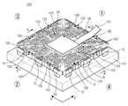
Translated fromKorean도 1은 본 발명의 바람직한 실시 예에 따른 손떨림 보정 장치를 구비하는 카메라 렌즈 어셈블리의 구성을 나타내는 도면,1 is a view showing the configuration of a camera lens assembly having a camera shake correction apparatus according to a preferred embodiment of the present invention,
도 2는 도 1에 도시된 카메라 렌즈 어셈블리의 손떨림 보정 장치를 나타내는 단면 구성도,FIG. 2 is a cross-sectional configuration diagram illustrating an image stabilizer of the camera lens assembly illustrated in FIG. 1;
도 3은 도 2에 도시된 손떨림 보정 장치를 나타내는 사시도,3 is a perspective view of the image stabilizer shown in FIG. 2;
도 4는 도 3에 도시된 손떨림 보정 장치의 탄성부를 나타내는 평면도,4 is a plan view illustrating an elastic part of the image stabilizer shown in FIG. 3;
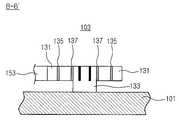
도 5는 도 3에 도시된 라인 B-B'을 따라 손떨림 보정 장치의 탄성부를 절개하여 나타내는 단면도,FIG. 5 is a cross-sectional view illustrating the elastic part of the image stabilizer cut along the line BB ′ shown in FIG. 3;
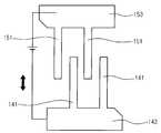
도 6은 도 3에 도시된 손떨림 보정 장치의 빗살 구조를 설명하기 위한 도면,6 is a view for explaining the comb teeth structure of the image stabilizer shown in FIG.
도 7은 도 3에 도시된 손떨림 보정 장치의 빗살 구조의 동작을 설명하기 위한 도면,7 is a view for explaining the operation of the comb teeth structure of the image stabilizer shown in FIG.
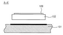
도 8은 도 3에 도시된 라인 A-A'을 따라 고정성 기판과 유동성 기판을 절개한 모습을 나타내는 도면,8 is a view showing a state in which the fixed substrate and the fluid substrate is cut along the line A-A 'shown in FIG.
본 발명은 카메라 장치에 관한 것으로서, 특히 카메라 렌즈 어셈블리의 손떨림 보정 장치에 관한 것이다.The present invention relates to a camera device, and more particularly to a camera shake correction device of the camera lens assembly.
CCD(Charge Coupled Device) 센서와 CMOS(Complementary Metal Oxide Semiconductor) 센서는 동영상 및 정지영상을 촬영하는 2차원 센서의 일종이며 전자식 카메라를 구성하는데 핵심적인 역할을 하고 있다. 특히 CCD센서는 화질면에서 CMOS 센서 보다 우수한 특성을 내나, 소모 전력 및 복잡한 구성의 단점 때문에 CMOS 영상센서가 그 시장의 점유율을 높여 가고 있으며 최근에 와서는 CMOS 센서도 화질면에서도 개선이 따르고 있다. 이러한 이미지 센서들이 발달하면서 디지털 카메라의 사용이 일반화되고, 셀룰러 폰(cellular phone)과 같은 휴대용 단말기에도 카메라 장치가 설치되기에 이르렀다.Charge Coupled Device (CCD) sensors and Complementary Metal Oxide Semiconductor (CMOS) sensors are two-dimensional sensors that capture video and still images, and play a key role in the construction of electronic cameras. In particular, the CCD sensor is superior to the CMOS sensor in terms of image quality, but the CMOS image sensor is increasing its market share due to the drawbacks of power consumption and complex configuration. Recently, the CMOS sensor has also been improved in image quality. With the development of these image sensors, the use of digital cameras has become commonplace, and camera devices have been installed in portable terminals such as cellular phones.
상기한 이미지 센서들을 이용한 일반적인 동영상 뿐만 아니라 정지 영상 촬영 카메라에 있어서 카메라의 외부적인 요소에 의한 떨림, 즉 손떨림 혹은 차량 탑재등에 의한 진동에 의하여 불안정하게 떨리는 영상이 촬영되는 경우가 많다. 이러한 불안정한 영상을 해소하기 위하여 그 움직임을 보상하는 장치 등이 제안되었다. 이러한 움직임 안정화 장치는 움직임 검출부와 움직임 보정 부분으로 나누어진다.In a still image photographing camera as well as a general video using the image sensors, an image that is unstablely shaken by an external element of the camera, that is, a vibration due to a hand shake or a vehicle is often taken. In order to solve such an unstable image, a device for compensating for the movement has been proposed. The motion stabilization device is divided into a motion detector and a motion compensation part.
움직임 검출부는 자이로 센서(Gyro Sensor) 등에 의한 기구의 움직임을 예측하는 방법과 영상 신호처리에 의하여 영상의 움직임 부분을 매 프레임 검출하는 방 법이 제안되고 사용된다. 또한, 검출된 움직임 정보를 굴절 가능한 렌즈(액티브 프리즘)를 사용하여 입사광을 임의로 굴절시키거나 이미지 센서의 입력 위치를 제어함으로써 불안정한 영상을 해소하고 선명한 영상을 얻게 된다.The motion detection unit is proposed and used a method of predicting the movement of the instrument by a gyro sensor and the like and a method of detecting the motion part of the image every frame by image signal processing. In addition, by using a lens (active prism) that can refract the detected motion information, the incident light is refracted arbitrarily or the input position of the image sensor is controlled to solve the unstable image and obtain a clear image.
이러한 카메라의 움직임에 따른 불안정한 영상 해소를 위하여 보이스 코일 모터(voice coil motor)를 이용하여 렌즈를 구동시키는 기술이 미국 등록특허 제5,398,132호(1995. 3. 14)에 개시되고 있다. 개시된 영상 안정화 장치는 보정 렌즈의 일측에 피치 코일(pitch coil)과 피치 요크(pitch yoke)를 설치하여 제1 방향으로 보정 렌즈를 구동시키고, 타측에 요 코일(yaw coil)과 요 요크(yaw yoke)를 설치하여 제1 방향에 수직하는 제2 방향으로 보정 렌즈를 구동시키는 구성이다. 즉, 카메라의 움직임에 따라 보정 렌즈를 구동시켜 광축을 원래의 위치로 복귀시킴으로써 영상을 안정화시키는 것이다.A technique for driving a lens using a voice coil motor to solve an unstable image caused by the movement of the camera is disclosed in US Patent No. 5,398,132 (March 14, 1995). The disclosed image stabilization device installs a pitch coil and a pitch yoke on one side of a correction lens to drive the correction lens in a first direction, and a yaw coil and a yoke on the other side of the correction lens. ) To drive the correction lens in a second direction perpendicular to the first direction. That is, the image is stabilized by driving the correction lens in accordance with the movement of the camera to return the optical axis to its original position.
그러나, 최근에는 랩탑(lap-top) 컴퓨터, 휴대 전화 등 휴대용 단말기들에 카메라 장치가 장착되어 휴대용 단말기의 기능 확장에 기여하고 있으나, 사용자의 손떨림 등에 의한 영상을 보정하기 위한 장치들은 휴대용 단말기의 소형, 경량화에 장애가 되고 있다.Recently, however, camera devices have been installed in portable terminals such as laptop computers and mobile phones, thereby contributing to the expansion of the functions of portable terminals. It is an obstacle to weight reduction.
상기와 같은 문제점들을 해결하기 위하여, 본 발명의 목적은 소형, 경량화가 용이한 카메라 렌즈 어셈블리의 손떨림 보정 장치를 제공함에 있다.In order to solve the above problems, it is an object of the present invention to provide a camera shake assembly of the camera lens assembly that is easy to compact, lightweight.
상기와 같은 목적을 달성하기 위하여, 본 발명은 카메라 렌즈 어셈블리의 손 떨림 보정 장치에 있어서,In order to achieve the above object, the present invention is a camera shake correction device,
고정성 기판;Fixed substrates;
상기 기판 상에 유동 가능하게 배치되는 유동성 기판;A flowable substrate disposed to be flowable on the substrate;
상기 유동성 기판의 주변을 둘러싸게 제공되고, 상기 고정성 기판 상에 고정된 고정성 빗살(comb) 구조; 및A fixed comb structure provided surrounding the periphery of the flowable substrate and fixed on the fixed substrate; And
상기 유동성 기판의 주변을 둘러싸게 제공되고, 상기 유동성 기판과 함께 상기 고정성 기판 상에서 유동 가능하게 구성되는 유동성 빗살 구조를 포함하고,A fluid comb structure provided surrounding the periphery of the flowable substrate and configured to flow on the fixed substrate together with the flowable substrate,
상기 고정성 빗살 구조와 유동성 빗살 구조에 전압이 인가됨에 따라 상기 고정성 빗살 구조와 유동성 빗살 구조 사이에 작용하는 인력에 의해 상기 유동성 기판이 유동하는 카메라 렌즈 어셈블리의 손떨림 보정 장치를 개시한다.
Disclosed is a camera shake assembly of a camera lens assembly in which the fluid substrate flows due to an attractive force acting between the fixed comb structure and the fluid comb structure as voltage is applied to the fixed comb structure and the fluid comb structure.
이하 본 발명의 바람직한 실시 예를 첨부된 도면을 참조하여 상세히 설명하면 다음과 같다. 본 발명을 설명함에 있어서, 관련된 공지기능 혹은 구성에 대한 구체적인 설명이 본 발명의 요지를 불필요하게 흐릴 수 있다고 판단되는 경우 그 상세한 설명을 생략한다.Hereinafter, exemplary embodiments of the present invention will be described in detail with reference to the accompanying drawings. In the following description of the present invention, if it is determined that the detailed description of the related known function or configuration may unnecessarily obscure the subject matter of the present invention, the detailed description thereof will be omitted.
도 1은 본 발명의 바람직한 실시 예에 따른 손떨림 보정 장치(100)를 구비하는 카메라 렌즈 어셈블리(10)를 나타내는 분리 사시도이고, 도 2는 도 1에 도시된 카메라 어셈블리(10)를 나타내는 단면 구성도이다.1 is an exploded perspective view illustrating a
도 1과 도 2에 도시된 바와 같이, 본 발명의 바람직한 실시 예에 따른 손떨 림 보정 장치(100)는 상부 및 하부 하우징(11, 12)으로 구성된 렌즈 하우징에 수용되고, 상기 상부 하우징(11) 상에는 적어도 하나 이상의 렌즈(15)로 구성된 렌즈 조립체(13)가 결합된다.1 and 2, the image stabilizer 100 according to an exemplary embodiment of the present invention is accommodated in a lens housing including upper and
상기 손떨림 보정 장치(100)에는 CCD소자 또는 CMOS소자 등의 이미지 센서가 설치되며, 그로부터 연장되는 가요성 인쇄회로(191)는 상기 하부 하우징(12) 상에 형성된 배선홈(199)을 통해 상기 렌즈 하우징의 외부로 인출된다.An image sensor such as a CCD device or a CMOS device is installed in the
도 3은 본 발명의 바람직한 실시 예에 따른 카메라 렌즈 어셈블리(10)의 손떨림 보정 장치(100)를 나타내는 사시도이고, 도 4는 도 3에 도시된 손떨림 보정 장치(100)의 탄성부(103)의 구성을 나타내는 평면도이다.3 is a perspective view illustrating the
도 3과 도 4에 도시된 바와 같이, 본 발명의 바람직한 실시 예에 따른 카메라 렌즈 어셈블리(10)의 손떨림 보정 장치(100)는 고정성 기판(101) 상에서 유동 가능한 유동성 기판(102)을 설치하고, 상기 유동성 기판(102) 주위에 빗살 구조물(104, 105)을 형성하여 상기 빗살 구조물(104, 105)에 전압을 인가시킴으로써 전압차에 의해 발생되는 인력으로 상기 유동성 기판(102)을 유동시키는 구조이다. 상기 빗살 구조물(104, 105)에 전압의 공급이 중단되면, 상기 탄성부(103)는 상기 유동성 기판(102)을 초기 위치로 복귀시키게 되며, 이는 상기 탄성부(103)에 구성된 탄성편(135, 137)들에 의해 이루어진다. 상기 유동성 기판(102) 상에는 이미지 센서(109)가 설치된다.As shown in FIGS. 3 and 4, the
도 3과 도 8을 참조하면, 상기 유동성 기판(102)은 그의 상면에 이미지 센서(109)가 설치되고, 상기 고정성 기판(101)과 이격된 상태를 유지한다. 따라서, 그 의 주위에 설치된 빗살 구조물(104, 105)로부터 인력이 발생되면 상기 유동성 기판(102)이 상기 고정성 기판(101) 상에서 유동할 수 있는 것이다.3 and 8, the
상기 빗살 구조물(104, 105)은 상기 유동성 기판(102)의 주변 사방을 둘러싸게 설치된다. 상기 빗살 구조물(104, 105)은 상기 고정성 기판 상(101)에 고정된 고정성 빗살 구조(104)와, 상기 고정성 기판(101) 상에서 상기 유동성 기판(102)과 함께 유동하는 유동성 빗살 구조(105)로 구성된다. 본 발명의 바람직한 실시 예를 설명함에 있어서, 상기 유동성 기판(102)의 양측(①, ②)에 각각 설치된 빗살 구조물(104, 105)은 제1 고정성 및 제1 유동성 빗살 구조로 지칭하고, 상기 유동성 기판(102)의 양단(③, ④)에 각각 설치된 빗살 구조물(104, 105)은 제2 고정성 및 제2 유동성 빗살 구조로 지칭하기로 한다.The
상기 고정성 빗살 구조(104)는 상기 고정성 기판(101) 상에 고정된 상태로 상기 유동성 기판(102)의 주변을 둘러싸게 설치된다. 상기 유동성 빗살 구조(105)는 상기 고정성 빗살 구조(104) 사이의 공간을 따라 형성되고, 상기 고정성 기판(101) 상에서 상기 유동성 기판(102)과 함께 유동 가능한 상태로 상기 유동성 기판(102)을 둘러싸게 설치된다. 상기 유동성 빗살 구조(105)의 일단은 상기 유동성 기판(102)의 가장자리에 고정되고, 타단은 소정의 탄성부(103)를 통해 상기 고정성 기판(101) 상에 고정된다. 상기 탄성부(103)의 탄성 변형은 상기 유동성 빗살 구조(105)의 유동을 가능하게 하면서, 상기 유동성 빗살 구조(105)가 유동한 경우 전압의 공급이 중단되면 최초의 위치로 되돌아가게 하는 탄성 복원력을 제공한다.The
도 3에 도시된 바와 같이, 상기 빗살 구조물(104, 105)은 미로형태의 대단히 복잡한 패턴으로 구성되는데, 이는 미세 장치의 집적화를 위해 사용되는 방법인 마이크로머시닝(micromachining) 기법으로 제작된다. 이는 반도체 가공기술의 일종이며, 흔히 MEMS(Micro Electro Mechanical Systems)라 지칭되는 기술의 일종이다. MEMS(Micro Electro Mechanical Systems)란, 반도체 공정, 특히 집적회로 기술을 응용한 마이크로머시닝 기술을 이용하여 ㎛ 단위의 초소형 센서나 액추에이터 및 전기 기계적 구조물을 제작하는 분야를 의미한다. 마이크로머시닝 기술에 의하여 제작된 미세 기계는 mm 이하의 크기 및 ㎛ 이하의 정밀도를 구현할 수 있다.As shown in FIG. 3, the
마이크로머시닝 기술의 장점은 초정밀 미세 가공을 통하여 소형화, 고성능화, 다기능화, 집적화를 가능하게 하며, 안정성 및 신뢰성을 향상시킬 수 있다는 것이다. 아울러, 일체화된 집적 시스템의 구현 가능으로 조립 필요성이 감소되며, 일괄공정으로 제작되므로 저렴한 비용으로 대량 생산이 가능하다. 이는 본 발명의 바람직한 실시 예에 따른 손떨림 보정 장치를 제작하기 위한 하나의 공법으로서, 상기 손떨림 보정 장치의 구조에 직접적으로 관련되는 구성요소는 아니므로 그 상세한 설명은 생략하기로 한다.The advantages of micromachining technology are miniaturization, high performance, multifunctionality and integration through ultra-precision micromachining, and stability and reliability can be improved. In addition, it is possible to implement an integrated integrated system to reduce the need for assembly, and because it is manufactured in a batch process it is possible to mass production at a low cost. This is a construction method for manufacturing a camera shake correction apparatus according to a preferred embodiment of the present invention, and since it is not a component directly related to the structure of the camera shake correction apparatus, a detailed description thereof will be omitted.
상기 유동성 기판(102), 고정성 빗살 구조(104) 및 유동성 빗살 구조(105)는 MEMS 기법에 의해 동시에 제작된다. 즉, 상기 고정성 기판(101) 상에 적층된 적층물을 MEMS 기법으로 식각하여, 유동성 기판(102), 고정성 빗살 구조(104) 및 유동성 빗살 구조(105)를 동시에 제작하게 되는 것이다. MEMS 기법을 적용하기 위하여 상기 고정성 기판(101)은 유리(glass) 기판으로 제작되고, 상기 유동성 기판(102), 고정성 빗살 구조(104) 및 유동성 빗살 구조(105)를 제작하기 위한 적층물은 규소 (Si) 층이 적합하다.The
이하에서는 도 6을 더 참조하여 상기 고정성 빗살 구조(104)와 유동성 빗살 구조(105)를 살펴보기로 한다. 도 6은 상기 손떨림 보정 장치(100)의 제1 고정성 빗살 구조와 제1 유동성 빗살 구조를 설명하기 위한 도면이며, 제2 고정성 및 제2 유동성 빗살 구조는 상기 제1 고정성 및 제1 유동성 빗살 구조와 동일하며 그 방향성에 차이가 있는 것으로 그의 도면 및 참조부호는 생략하기로 한다.Hereinafter, the fixed
상기 고정성 빗살 구조(104)는 다수의 고정성 리브(141)들과 상기 고정성 리브(141)들을 트리(tree) 구조로 연결하는 제1 연결리브(143)들로 구성된다.The fixed
상기 제1 고정성 빗살 구조를 구성하는 다수의 제1 고정성 리브(141)들은 제1 방향(X)으로 연장되고, 상기 제1 방향(X)에 수직하는 제2 방향(Y)을 따라 배열된다. 각각의 상기 제1 고정성 리브(141)들은 상기 제1 연결리브(143)들을 통해 각각 연결된다. 상기 제1 연결리브(143)들의 단부는 상기 고정성 기판(101)의 가장자리에 인접하게 위치되며, 그 상면에는 상기 제1 고정성 빗살 구조에 전압을 인가하기 위한 전극(19)이 각각 설치된다.The plurality of first fixing
상기 제2 고정성 빗살 구조는 상기 제1 고정성 빗살 구조와 동일하게 구성되며, 다만 다수의 제2 고정성 리브들은 상기 제2 방향(Y)으로 연장되고 상기 제1 방향(X)으로 배열된다는 점에서 차이가 있으며, 상기 제1 연결리브(143)들을 통해 각각 연결되고 상기 제1 연결리브(143)들의 단부에 제공된 전극(19)을 통해 전압을 인가받는 것도 상기 제1 고정성 빗살 구조와 동일하다.The second fixed comb structure has the same structure as the first fixed comb structure, except that the plurality of second fixed ribs extend in the second direction (Y) and are arranged in the first direction (X). In this respect, the first fixed comb structure is connected to each other through the first connecting
상기 유동성 빗살 구조(105)는 다수의 유동성 리브(151)들과 상기 유동성 리 브(151)들을 트리(tree) 구조로 연결하는 제2 연결리브(153)들로 구성된다.The
상기 제1 유동성 빗살 구조를 구성하는 다수의 제1 유동성 리브(151)들은 제1 방향(X)으로 연장되고, 상기 제1 방향(X)에 수직하는 제2 방향(Y)을 따라 배열된다. 각각의 상기 제1 유동성 리브(151)들은 상기 제2 연결리브(153)들을 통해 각각 연결된다. 이때, 상기 제1 유동성 리브(151)들은 상기 제1 고정성 리브(141)들 사이사이에 각각 배치된다. 즉, 상기 제1 고정성 리브(141)들과 제1 유동성 리브(151)들은 상기 제2 방향(Y)을 따라 번갈아가며 배치되는 것이다.The plurality of first
상기 제2 연결리브(153)들의 단부는 탄성 복원력을 갖는 상기 탄성부(103)를 통해 상기 고정성 기판(101)의 가장자리에 인접하는 위치에 고정되며, 그 상면에는 상기 제1 유동성 빗살 구조에 전압을 인가하기 위한 전극(19)이 각각 설치된다.Ends of the
상기 제2 유동성 빗살 구조는 상기 제1 유동성 빗살 구조와 동일하게 구성되며, 다만 다수의 제2 유동성 리브들이 상기 제2 방향(Y)으로 연장되고 상기 제1 방향(X)으로 배열된다는 점에서 차이가 있으며, 상기 제2 연결리브(153)들을 통해 각각 연결되고 상기 제2 연결리브(153)들의 단부에 제공된 전극을 통해 전압을 인가받는 것도 상기 제1 유동성 빗살 구조와 동일하다. 또한, 상기 제2 유동성 리브들은 상기 제2 고정성 리브들 사이사이에 각각 배치되는 구성 또한 상기 제1 유동성 리브(151)들의 구성과 동일하다.The second flowable comb structure is configured in the same manner as the first flowable comb structure, except that a plurality of second flowable ribs extend in the second direction (Y) and are arranged in the first direction (X). In addition, each of the second connecting
도 7을 참조하면 상기와 같이 구성된 빗살 구조물(104, 105)은, 각각의 전극에 전압이 인가되었을 때 상기 제1 연결리브(143)와, 상기 제1 연결리브(143)에 마주하는 제2 연결리브(153) 사이에서 인력을 발생시키게 된다. 발생된 인력은 상기 유동성 빗살 구조의 유동을 유발하고 이는 결국 상기 유동성 기판(102)의 유동으로 나타난다.Referring to FIG. 7, the comb-
① 측의 상기 제1 고정성 빗살 구조와 제1 유동성 빗살 구조에 전압이 인가되면 인가된 전압에 의해 상기 유동성 기판(102)은 제1 방향(X)으로 유동하게 되고, ③ 측의 상기 제2 고정성 빗살 구조와 제2 유동성 빗살 구조에 전압이 인가되면 인가된 전압에 의해 따라 상기 유동성 기판(102)은 제2 방향(Y)으로 유동하게 된다. 상기 ① 측 또는 ③측에 전압의 공급이 중단되면, 상기 탄성부(103)의 복원력에 의해 상기 유동성 기판(102)은 초기 위치로 복귀된다. 마찬가지로 ② 측의 상기 제1 고정성 빗살 구조와 제1 유동성 빗살 구조에 전압이 인가되면 상기 유동성 기판(102)은 상기 제1 방향의 역방향(-X)으로 유동하고, ④ 측의 제2 고정성 빗살 구조와 제2 유동성 빗살 구조에 전압이 인가되면 상기 유동성 기판(102)은 상기 제2 방향의 역방향(-Y) 방향으로 유동하게 된다.When a voltage is applied to the first fixed comb tooth structure and the first fluid comb structure on the ① side, the
결과적으로, 상기 손떨림 보정 장치(100)는 상기 유동성 기판(102)을 유동시키고자 하는 방향에 전압을 인가함으로써 손떨림 등으로 인한 영상을 보정하게 되며, 전압의 공급이 중단되면 상기 탄성부(103)의 복원력에 의해 상기 유동성 기판(102)은 최초 위치로 복귀하게 된다.As a result, the
도 4와 도 5를 참조하면, 상기 탄성부(103)는 상기 제2 연결리브(153)의 단부에 각각 설치되며, 상기 고정성 기판(101)의 가장자리에 인접하게 위치된다. 상기 탄성부(103)는 상기 제2 연결리브(153)의 단부에 형성된 제1 연결단(131), 상기 제1 연결단(131)과 이격된 위치에서 마주보게 형성되는 제2 연결단(132), 상기 제1 연결단(131)과 제2 연결단(132) 사이에 위치되고 상기 고정성 기판(101) 상에 고정된 고정단(133)으로 구성된다. 상기 제1 연결단(131)과 제2 연결단(132)은 상기 고정성 기판(101)과 이격된 상태로 설치되어 상기 고정성 기판(101) 상에서 유동 가능하다. 상기 제2 연결리브(153)의 단부에 제공된 전극(19)은 상기 고정단(133)의 상면에 설치된다.4 and 5, the
상기 제1 연결단(131)과 제2 연결단(132)은 제1 탄성편(135)에 의해 연결되고, 상기 제2 연결단(132)과 고정단(133)은 제2 탄성편(137)에 의해 연결된다. 상기 제1 및 제2 탄성편(135, 137)은 상기 유동성 빗살 구조가 유동하였을 때 원래의 위치로 되돌아가게 하는 탄성 복원력을 제공한다.The
이때, 상기 제1 탄성편(135)과 제2 탄성편(137)은 각각 한 쌍이 서로 마주보게 설치될 수 있으며, 상기 제2 탄성편(137)들은 상기 제1 탄성편(135)들 사이에 설치된다.In this case, the pair of first
상기 탄성부(103)는 상기 유동성 빗살 구조와 일체형으로 MEMS 기법에 의해 형성된다.The
상기 유동성 기판(102)의 양측(①, ②)에 각각 설치되는 탄성부(103)는 상기 유동성 기판(102)이 상기 제1 방향(X) 또는 그 역방향(-X)으로 유동할 때 원래의 위치로 되돌아가게 하는 탄성 복원력을 제공한다. 마찬가지로, 상기 유동성 기판(102)의 양단(③, ④)에 각각 설치되는 탄성부(103)는 상기 유동성 기판(102)이 상기 제2 방향(Y) 또는 그 역방향(-Y)으로 유동할 때 원래의 위치로 되돌아가게 하는 탄성 복원력을 제공하게 된다.The
상기와 같이 구성된 탄성부(103)는 상기 제2 연결리브(153)의 일단, 즉 상기 유동성 기판(102)에 인접하는 위치에도 설치될 수 있다. 이는 상기 유동성 빗살 구조(105)의 구조적 안정성을 향상시키고, 상기 손떨림 보정 장치(100)의 신뢰성을 향상시키는데 유용하다. 상기 유동성 기판(102)에 인접하는 위치에 설치되는 탄성부(103')는 상기 고정성 기판(101)의 가장자리에 인접한 위치에 설치된 탄성부(103)와 그 형상에 있어서 다소 차이가 있을 수 있다.The
다시 도 6을 참조하면, 상기 유동성 빗살 구조(105)와 유동성 기판(102)은 다수의 서스펜션(suspension)(159)들을 통해 연결된다. 상기 다수의 서스펜션(159)은 상기 유동성 기판(102)의 양측(①, ②)에 위치되는 제1 서스펜션과, 양단(③, ④)에 위치되는 제2 서스펜션으로 구분된다.Referring again to FIG. 6, the
상기 제1 서스펜션은 상기 제1 유동성 빗살 구조의 유동을 상기 유동성 기판(102)에 전달하여 상기 유동성 기판(102)을 상기 제1 방향(X)으로 유동시키면서, 상기 유동성 기판(102)이 상기 제2 방향(Y) 또는 그 역방향(-Y)으로 유동하는 것을 허용하게 된다. 즉, 상기 유동성 기판(102)이 상기 제2 방향(Y) 또는 그 역방향(-Y)으로 유동하는 때 상기 제1 서스펜션이 탄성 변형을 일으키면서, 상기 유동성 기판(102)의 상기 제2 방향(Y) 또는 그 역방향(-Y)을 따르는 유동이 상기 제1 유동성 빗살 구조로 전달되는 것을 방지한다.The first suspension is configured to transfer the flow of the first flowable comb structure to the
상기 제2 서스펜션은 상기 제2 유동성 빗살 구조의 유동을 상기 유동성 기판(102)에 전달하여 상기 유동성 기판(102)을 상기 제2 방향(Y)으로 유동시키면서, 상기 유동성 기판(102)이 상기 제1 방향(X) 또는 그 역방향(-X)으로 유동하는 것을 허용하게 된다. 즉, 상기 유동성 기판(102)이 상기 제1 방향(X)으로 유동하는 때 상기 제2 서스펜션이 상기 제1 방향(X) 또는 그 역방향(-X)으로 탄성 변형을 일으키면서, 상기 유동성 기판(102)의 상기 제1 방향(X) 또는 그 역방향(-X)을 따르는 유동이 상기 제2 유동성 빗살 구조로 전달되는 것을 방지한다.The second suspension transmits the flow of the second flowable comb structure to the
상기와 같이 구성된 손떨림 보정 장치(100)는, 카메라 장치에 설치되어 사용자의 손떨림 등에 의한 카메라의 흔들림을 검출하는 각속도 센서 또는 자이로 센서로부터 검출되는 카메라의 흔들림 양과 속도에 따라 제어신호를 제공받게 된다. 제어신호라 함은 상기 전극(19)들에 인가되는 전압이 될 것이다. 카메라의 흔들림 양과 속도에 따라 상기 손떨림 보정 장치(100)의 전극(19)들에 전압이 인가되면, 상기 빗살 구조물(104, 105)들 간에 작용하는 정전기력은 상기 유동성 빗살 구조의 유동을 발생시켜 결과적으로 상기 유동성 기판(102)을 유동시키게 된다.The camera
이상, 본 발명의 상세한 설명에서는 구체적인 실시 예에 관해서 설명하였으나, 본 발명의 범위에서 벗어나지 않는 한도 내에서 여러 가지 변형이 가능함은 당해 분야에서 통상의 지식을 가진 자에게 있어서 자명하다 할 것이다.In the foregoing detailed description of the present invention, specific embodiments have been described. However, it will be apparent to those skilled in the art that various modifications can be made without departing from the scope of the present invention.
상술한 바와 같이, 본 발명에 따른 카메라 렌즈 어셈블리의 손떨림 보정 장치는 이미지 센서가 설치되는 유동성 기판과, 사용자의 손떨림 등 카메라의 흔들림에 따라 유동성 기판을 유동시키기 위한 보정 장치는 고정성 기판 상의 적층물을 식각하여 제작함으로써 제작이 용이하고, MEMS 기법을 활용하여 제작함으로써 손떨 림 보정 장치의 소형화 및 제품의 정밀도 향상에 기여하게 되었다. 결과적으로, 카메라 렌즈 어셈블리가 소형화됨에 따라, 노트북, 셀룰러 폰 등 휴대용 단말기에 카메라 렌즈 어셈블리의 장착이 용이하게 되었다.As described above, the image stabilization device of the camera lens assembly according to the present invention is a fluid substrate on which the image sensor is installed, and a compensation device for flowing the fluid substrate in accordance with the shake of the camera, such as the user's hand shake is a laminate on a fixed substrate It is easy to manufacture by etching, and by using MEMS method, it contributes to miniaturization of image stabilization device and improvement of product precision. As a result, as the camera lens assembly is miniaturized, it is easy to mount the camera lens assembly to a portable terminal such as a notebook or a cellular phone.
Claims (21)
Translated fromKoreanPriority Applications (3)
| Application Number | Priority Date | Filing Date | Title |
|---|---|---|---|
| KR1020040089171AKR100584424B1 (en) | 2004-11-04 | 2004-11-04 | Image stabilizer in camera lens assembly |
| US11/076,382US7489340B2 (en) | 2004-11-04 | 2005-03-09 | Optical image stabilizer for camera lens assembly |
| JP2005136432AJP4168042B2 (en) | 2004-11-04 | 2005-05-09 | Camera lens assembly image stabilizer |
Applications Claiming Priority (1)
| Application Number | Priority Date | Filing Date | Title |
|---|---|---|---|
| KR1020040089171AKR100584424B1 (en) | 2004-11-04 | 2004-11-04 | Image stabilizer in camera lens assembly |
Publications (2)
| Publication Number | Publication Date |
|---|---|
| KR20060040003A KR20060040003A (en) | 2006-05-10 |
| KR100584424B1true KR100584424B1 (en) | 2006-05-26 |
Family
ID=36261478
Family Applications (1)
| Application Number | Title | Priority Date | Filing Date |
|---|---|---|---|
| KR1020040089171AExpired - Fee RelatedKR100584424B1 (en) | 2004-11-04 | 2004-11-04 | Image stabilizer in camera lens assembly |
Country Status (3)
| Country | Link |
|---|---|
| US (1) | US7489340B2 (en) |
| JP (1) | JP4168042B2 (en) |
| KR (1) | KR100584424B1 (en) |
Families Citing this family (65)
| Publication number | Priority date | Publication date | Assignee | Title |
|---|---|---|---|---|
| JP4506529B2 (en)* | 2005-03-18 | 2010-07-21 | オムロン株式会社 | Electrostatic microswitch and method for manufacturing the same, and apparatus provided with electrostatic microswitch |
| CN100468117C (en)* | 2005-09-23 | 2009-03-11 | 鸿富锦精密工业(深圳)有限公司 | Digital Camera Module |
| CN100468116C (en)* | 2005-09-23 | 2009-03-11 | 鸿富锦精密工业(深圳)有限公司 | Digital Camera Module |
| JP4972783B2 (en)* | 2006-07-20 | 2012-07-11 | コニカミノルタアドバンストレイヤー株式会社 | Imaging unit and imaging apparatus |
| US8138564B2 (en)* | 2006-07-20 | 2012-03-20 | Konica Minolta Opto, Inc. | Image sensor unit and image sensor apparatus |
| US8768157B2 (en) | 2011-09-28 | 2014-07-01 | DigitalOptics Corporation MEMS | Multiple degree of freedom actuator |
| US8619378B2 (en) | 2010-11-15 | 2013-12-31 | DigitalOptics Corporation MEMS | Rotational comb drive Z-stage |
| JP2008203402A (en)* | 2007-02-19 | 2008-09-04 | Konica Minolta Opto Inc | Sensor device and imaging apparatus |
| JP2008203719A (en)* | 2007-02-22 | 2008-09-04 | Konica Minolta Opto Inc | Lens driving apparatus, imaging apparatus and mobile terminal |
| US8098289B2 (en)* | 2007-05-02 | 2012-01-17 | Lite-On Technology Corporation | Micro-optical image stabilizer |
| TWM322407U (en)* | 2007-05-02 | 2007-11-21 | Lite On Technology Corp | Micro-optical image stabilizer |
| KR101371775B1 (en) | 2007-07-09 | 2014-03-24 | 삼성전자주식회사 | Method and apparatus for image stabilization on camera |
| KR101465081B1 (en)* | 2008-05-21 | 2014-11-25 | 디지털옵틱스 코포레이션 | Camera Module Having MEMS Actuator |
| WO2010144635A1 (en)* | 2009-06-09 | 2010-12-16 | Gregory David Gallinat | Cameras, camera apparatuses, and methods of using same |
| US9352962B2 (en) | 2010-11-15 | 2016-05-31 | DigitalOptics Corporation MEMS | MEMS isolation structures |
| US8608393B2 (en) | 2010-11-15 | 2013-12-17 | DigitalOptics Corporation MEMS | Capillary actuator deployment |
| US9061883B2 (en) | 2010-11-15 | 2015-06-23 | DigitalOptics Corporation MEMS | Actuator motion control features |
| US8884381B2 (en) | 2010-11-15 | 2014-11-11 | DigitalOptics Corporation MEMS | Guard trench |
| US8803256B2 (en) | 2010-11-15 | 2014-08-12 | DigitalOptics Corporation MEMS | Linearly deployed actuators |
| US9019390B2 (en) | 2011-09-28 | 2015-04-28 | DigitalOptics Corporation MEMS | Optical image stabilization using tangentially actuated MEMS devices |
| US8521017B2 (en) | 2010-11-15 | 2013-08-27 | DigitalOptics Corporation MEMS | MEMS actuator alignment |
| US8547627B2 (en) | 2010-11-15 | 2013-10-01 | DigitalOptics Corporation MEMS | Electrical routing |
| US8604663B2 (en) | 2010-11-15 | 2013-12-10 | DigitalOptics Corporation MEMS | Motion controlled actuator |
| US8430580B2 (en) | 2010-11-15 | 2013-04-30 | DigitalOptics Corporation MEMS | Rotationally deployed actuators |
| US9515579B2 (en) | 2010-11-15 | 2016-12-06 | Digitaloptics Corporation | MEMS electrical contact systems and methods |
| US8947797B2 (en) | 2010-11-15 | 2015-02-03 | DigitalOptics Corporation MEMS | Miniature MEMS actuator assemblies |
| US8637961B2 (en) | 2010-11-15 | 2014-01-28 | DigitalOptics Corporation MEMS | MEMS actuator device |
| US9052567B2 (en) | 2010-11-15 | 2015-06-09 | DigitalOptics Corporation MEMS | Actuator inside of motion control |
| US8941192B2 (en) | 2010-11-15 | 2015-01-27 | DigitalOptics Corporation MEMS | MEMS actuator device deployment |
| US8605375B2 (en) | 2010-11-15 | 2013-12-10 | DigitalOptics Corporation MEMS | Mounting flexure contacts |
| KR101184913B1 (en)* | 2010-12-13 | 2012-09-20 | 엘지이노텍 주식회사 | Ois actuator and camera module having the same ois actuator |
| JP5624529B2 (en)* | 2011-09-27 | 2014-11-12 | 株式会社東芝 | Camera shake correction apparatus and imaging apparatus |
| US8616791B2 (en) | 2011-09-28 | 2013-12-31 | DigitalOptics Corporation MEMS | Rotationally deployed actuator devices |
| US8855476B2 (en) | 2011-09-28 | 2014-10-07 | DigitalOptics Corporation MEMS | MEMS-based optical image stabilization |
| KR101832496B1 (en)* | 2011-12-01 | 2018-02-26 | 삼성전기주식회사 | Camera module |
| USD689539S1 (en) | 2012-01-26 | 2013-09-10 | Michael Zaletel | Camera stabilizer |
| TWI490630B (en)* | 2013-07-22 | 2015-07-01 | Tdk Taiwan Corp | Lens driving device and manufacturing method thereof |
| KR20160140698A (en)* | 2014-04-04 | 2016-12-07 | 멤스 스타트 엘엘씨 | Actuator for moving an optoelectronic device |
| CN106460983B (en) | 2014-05-06 | 2018-11-13 | 麦斯卓有限公司 | Flexures, platforms including arrays of flexures, and methods of making flexures |
| US9621775B2 (en)* | 2014-05-06 | 2017-04-11 | Mems Drive, Inc. | Electrical bar latching for low stiffness flexure MEMS actuator |
| US9917991B2 (en) | 2014-10-24 | 2018-03-13 | Apple Inc. | Camera actuator |
| TW201630407A (en)* | 2015-02-13 | 2016-08-16 | Ue Technology Co Ltd | Image sensor system chip having image stabilization function and manufacturing method thereof |
| CN104717434B (en)* | 2015-03-27 | 2017-09-08 | 有医科技股份有限公司 | CIS System on Chip/SoC and its preparation method with image stabilization function |
| JP2017143092A (en)* | 2016-02-08 | 2017-08-17 | ソニー株式会社 | Glass interposer module, imaging device, and electronic equipment |
| CN106302988B (en)* | 2016-07-29 | 2017-12-19 | 广东欧珀移动通信有限公司 | Falling protection method and device for mobile terminal and mobile terminal |
| CN106254773B (en)* | 2016-07-29 | 2018-01-23 | 广东欧珀移动通信有限公司 | Optical image stabilization system, imaging device and electronic device |
| US12147059B2 (en)* | 2016-12-16 | 2024-11-19 | Hutchinson Technology Incorporated | Sensor shift structures in optical image stabilization suspensions |
| EP3555470A4 (en)* | 2016-12-16 | 2020-12-09 | Hutchinson Technology Incorporated | SENSOR DISPLACEMENT STRUCTURES IN SUSPENSIONS FOR THE STABILIZATION OF OPTICAL IMAGES |
| US11199182B2 (en)* | 2016-12-16 | 2021-12-14 | Hutchinson Technology Incorporated | Sensor shift structures in optical image stabilization suspensions |
| US11105319B2 (en) | 2017-05-05 | 2021-08-31 | Hutchinson Technology Incorporated | Shape memory alloy actuators and methods thereof |
| US11815794B2 (en) | 2017-05-05 | 2023-11-14 | Hutchinson Technology Incorporated | Shape memory alloy actuators and methods thereof |
| US11333134B2 (en) | 2017-05-05 | 2022-05-17 | Hutchinson Technology Incorporated | Shape memory alloy actuators and methods thereof |
| GB2602950B (en)* | 2017-05-05 | 2022-10-26 | Hutchinson Technology | Shape memory alloy actuators and methods thereof |
| CN112334827A (en)* | 2018-07-04 | 2021-02-05 | 索尼公司 | Shake correction device, driving device, imaging device, and electronic device |
| US11622064B2 (en) | 2018-11-20 | 2023-04-04 | Lg Innotek Co., Ltd. | Substrate for image sensor |
| CN111225130B (en) | 2018-11-23 | 2021-02-26 | 华为机器有限公司 | Imaging device and terminal equipment |
| KR20210081556A (en)* | 2019-12-24 | 2021-07-02 | 엘지이노텍 주식회사 | Driving apparatus of image sensor |
| CN113055556B (en)* | 2019-12-27 | 2022-07-08 | 中芯集成电路(宁波)有限公司 | Moving mechanism and driving method thereof, electronic equipment and imaging module |
| CN111212214B (en)* | 2020-03-19 | 2021-11-30 | 维沃移动通信有限公司 | Anti-shake mechanism, camera module and electronic equipment |
| CN113992814A (en) | 2020-07-27 | 2022-01-28 | 华为技术有限公司 | Voice coil motor, camera module and electronic equipment |
| US11194115B1 (en) | 2020-09-02 | 2021-12-07 | Hutchinson Technology Incorporated | Guided autofocus assembly |
| CN114200739A (en) | 2020-09-02 | 2022-03-18 | 哈钦森技术股份有限公司 | Guided autofocus assembly |
| US11859598B2 (en) | 2021-06-10 | 2024-01-02 | Hutchinson Technology Incorporated | Shape memory alloy actuators and methods thereof |
| CN119604811A (en)* | 2022-09-09 | 2025-03-11 | Oppo广东移动通信有限公司 | Camera components and electronics |
| US11982263B1 (en) | 2023-05-02 | 2024-05-14 | Hutchinson Technology Incorporated | Shape metal alloy (SMA) bimorph actuators with reduced wire exit angle |
Family Cites Families (13)
| Publication number | Priority date | Publication date | Assignee | Title |
|---|---|---|---|---|
| JPS63217778A (en) | 1987-03-05 | 1988-09-09 | Matsushita Electric Ind Co Ltd | Photography equipment |
| JP2890989B2 (en)* | 1992-07-29 | 1999-05-17 | 日本電気株式会社 | Image sensor position adjustment device for spacecraft mounted optical system |
| JPH0965491A (en)* | 1995-08-18 | 1997-03-07 | Hitachi Ltd | Electro-mechanical converter |
| JPH11183178A (en)* | 1997-12-16 | 1999-07-09 | Murata Mfg Co Ltd | Microoscillator |
| JP2001119917A (en)* | 1999-10-21 | 2001-04-27 | Asahi Optical Co Ltd | Electrostatic planar actuator |
| US6473122B1 (en)* | 1999-12-06 | 2002-10-29 | Hemanth G. Kanekal | Method and apparatus to capture high resolution images using low resolution sensors and optical spatial image sampling |
| WO2001063232A1 (en)* | 2000-02-24 | 2001-08-30 | University Of Virginia Patent Foundation | High sensitivity infrared sensing apparatus and related method thereof |
| KR100331453B1 (en) | 2000-07-18 | 2002-04-09 | 윤종용 | Position sensing apparatus for an electrostatic XY-stage using time-division multiplexing |
| JP2002103300A (en)* | 2000-09-22 | 2002-04-09 | Aisin Seiki Co Ltd | Manufacturing method of micromachine |
| JP4706105B2 (en)* | 2001-01-09 | 2011-06-22 | 株式会社ニコン | Imaging device |
| JP3972591B2 (en)* | 2001-03-27 | 2007-09-05 | セイコーエプソン株式会社 | Manufacturing method of fine structure |
| KR100468853B1 (en)* | 2002-08-30 | 2005-01-29 | 삼성전자주식회사 | MEMS comb actuator materialized on insulating material and method of manufacturing thereof |
| TWI250735B (en)* | 2004-11-25 | 2006-03-01 | Ind Tech Res Inst | Tunable type light transceiver module |
- 2004
- 2004-11-04KRKR1020040089171Apatent/KR100584424B1/ennot_activeExpired - Fee Related
- 2005
- 2005-03-09USUS11/076,382patent/US7489340B2/ennot_activeExpired - Fee Related
- 2005-05-09JPJP2005136432Apatent/JP4168042B2/ennot_activeExpired - Fee Related
Also Published As
| Publication number | Publication date |
|---|---|
| KR20060040003A (en) | 2006-05-10 |
| JP2006133730A (en) | 2006-05-25 |
| US20060092514A1 (en) | 2006-05-04 |
| US7489340B2 (en) | 2009-02-10 |
| JP4168042B2 (en) | 2008-10-22 |
Similar Documents
| Publication | Publication Date | Title |
|---|---|---|
| KR100584424B1 (en) | Image stabilizer in camera lens assembly | |
| US8248497B2 (en) | Image sensor device with movable sensor | |
| KR101940227B1 (en) | Micro electro mechanical systems device and apparatus for compensating tremble | |
| CN101266392B (en) | Image forming apparatus and optical apparatus | |
| CN101420526B (en) | Image sensor bearing device and camera module group | |
| KR101940478B1 (en) | Camera Module | |
| US9502464B2 (en) | Method of manufacturing optical image stabilizer | |
| US7800651B2 (en) | Image-stabilization driving device | |
| KR101961478B1 (en) | Camera Module | |
| CN113906339B (en) | Camera Module | |
| US8921146B2 (en) | Method for manufacturing optical image stabilizer employing scratch drive actuator | |
| KR100678268B1 (en) | Image stabilizer in camera lens assembly | |
| CN106132867A (en) | Actuator for moving photoconductor equipment | |
| JP4642659B2 (en) | Variable mirror | |
| CN114554038B (en) | Camera module and electronic equipment | |
| JP2008048388A (en) | Imaging unit and imaging apparatus | |
| KR101415038B1 (en) | Driving system and hand-shaking compensation apparatus adoptng the same | |
| US8000590B2 (en) | Driving apparatus, image capturing unit, and image capturing apparatus | |
| KR102029783B1 (en) | Micro electro mechanical systems device and apparatus for compensating tremble | |
| JP4924347B2 (en) | Moving mechanism, imaging unit, and imaging apparatus | |
| JP2008048387A (en) | Imaging unit and imaging apparatus | |
| JP2009071663A (en) | Movement mechanism and imaging apparatus | |
| JP2009034779A (en) | Driving device, imaging unit, imaging device, and manufacturing method of driving device | |
| US20250187904A1 (en) | Controllable Reflective Optical Unit With MEMS Tip-Tilt Actuator |
Legal Events
| Date | Code | Title | Description |
|---|---|---|---|
| A201 | Request for examination | ||
| PA0109 | Patent application | St.27 status event code:A-0-1-A10-A12-nap-PA0109 | |
| PA0201 | Request for examination | St.27 status event code:A-1-2-D10-D11-exm-PA0201 | |
| PN2301 | Change of applicant | St.27 status event code:A-3-3-R10-R13-asn-PN2301 St.27 status event code:A-3-3-R10-R11-asn-PN2301 | |
| PN2301 | Change of applicant | St.27 status event code:A-3-3-R10-R13-asn-PN2301 St.27 status event code:A-3-3-R10-R11-asn-PN2301 | |
| E701 | Decision to grant or registration of patent right | ||
| PE0701 | Decision of registration | St.27 status event code:A-1-2-D10-D22-exm-PE0701 | |
| PG1501 | Laying open of application | St.27 status event code:A-1-1-Q10-Q12-nap-PG1501 | |
| GRNT | Written decision to grant | ||
| PR0701 | Registration of establishment | St.27 status event code:A-2-4-F10-F11-exm-PR0701 | |
| PR1002 | Payment of registration fee | St.27 status event code:A-2-2-U10-U11-oth-PR1002 Fee payment year number:1 | |
| PG1601 | Publication of registration | St.27 status event code:A-4-4-Q10-Q13-nap-PG1601 | |
| PR1001 | Payment of annual fee | St.27 status event code:A-4-4-U10-U11-oth-PR1001 Fee payment year number:4 | |
| PR1001 | Payment of annual fee | St.27 status event code:A-4-4-U10-U11-oth-PR1001 Fee payment year number:5 | |
| PR1001 | Payment of annual fee | St.27 status event code:A-4-4-U10-U11-oth-PR1001 Fee payment year number:6 | |
| PR1001 | Payment of annual fee | St.27 status event code:A-4-4-U10-U11-oth-PR1001 Fee payment year number:7 | |
| R18-X000 | Changes to party contact information recorded | St.27 status event code:A-5-5-R10-R18-oth-X000 | |
| FPAY | Annual fee payment | Payment date:20130429 Year of fee payment:8 | |
| PR1001 | Payment of annual fee | St.27 status event code:A-4-4-U10-U11-oth-PR1001 Fee payment year number:8 | |
| FPAY | Annual fee payment | Payment date:20140429 Year of fee payment:9 | |
| PR1001 | Payment of annual fee | St.27 status event code:A-4-4-U10-U11-oth-PR1001 Fee payment year number:9 | |
| FPAY | Annual fee payment | Payment date:20150429 Year of fee payment:10 | |
| PR1001 | Payment of annual fee | St.27 status event code:A-4-4-U10-U11-oth-PR1001 Fee payment year number:10 | |
| FPAY | Annual fee payment | Payment date:20160428 Year of fee payment:11 | |
| PR1001 | Payment of annual fee | St.27 status event code:A-4-4-U10-U11-oth-PR1001 Fee payment year number:11 | |
| LAPS | Lapse due to unpaid annual fee | ||
| PC1903 | Unpaid annual fee | St.27 status event code:A-4-4-U10-U13-oth-PC1903 Not in force date:20170523 Payment event data comment text:Termination Category : DEFAULT_OF_REGISTRATION_FEE | |
| PC1903 | Unpaid annual fee | St.27 status event code:N-4-6-H10-H13-oth-PC1903 Ip right cessation event data comment text:Termination Category : DEFAULT_OF_REGISTRATION_FEE Not in force date:20170523 | |
| P22-X000 | Classification modified | St.27 status event code:A-4-4-P10-P22-nap-X000 | |
| P22-X000 | Classification modified | St.27 status event code:A-4-4-P10-P22-nap-X000 | |
| P22-X000 | Classification modified | St.27 status event code:A-4-4-P10-P22-nap-X000 |