KR100582314B1 - Method and apparatus for driving flow control electromagnetic proportional control valve - Google Patents
Method and apparatus for driving flow control electromagnetic proportional control valveDownload PDFInfo
- Publication number
- KR100582314B1 KR100582314B1KR1020047006482AKR20047006482AKR100582314B1KR 100582314 B1KR100582314 B1KR 100582314B1KR 1020047006482 AKR1020047006482 AKR 1020047006482AKR 20047006482 AKR20047006482 AKR 20047006482AKR 100582314 B1KR100582314 B1KR 100582314B1
- Authority
- KR
- South Korea
- Prior art keywords
- control valve
- solenoid
- driving
- proportional control
- solenoid proportional
- Prior art date
- Legal status (The legal status is an assumption and is not a legal conclusion. Google has not performed a legal analysis and makes no representation as to the accuracy of the status listed.)
- Expired - Fee Related
Links
Images


Classifications
- F—MECHANICAL ENGINEERING; LIGHTING; HEATING; WEAPONS; BLASTING
- F16—ENGINEERING ELEMENTS AND UNITS; GENERAL MEASURES FOR PRODUCING AND MAINTAINING EFFECTIVE FUNCTIONING OF MACHINES OR INSTALLATIONS; THERMAL INSULATION IN GENERAL
- F16K—VALVES; TAPS; COCKS; ACTUATING-FLOATS; DEVICES FOR VENTING OR AERATING
- F16K31/00—Actuating devices; Operating means; Releasing devices
- F16K31/02—Actuating devices; Operating means; Releasing devices electric; magnetic
- F16K31/06—Actuating devices; Operating means; Releasing devices electric; magnetic using a magnet, e.g. diaphragm valves, cutting off by means of a liquid
- F—MECHANICAL ENGINEERING; LIGHTING; HEATING; WEAPONS; BLASTING
- F02—COMBUSTION ENGINES; HOT-GAS OR COMBUSTION-PRODUCT ENGINE PLANTS
- F02D—CONTROLLING COMBUSTION ENGINES
- F02D41/00—Electrical control of supply of combustible mixture or its constituents
- F02D41/30—Controlling fuel injection
- F02D41/38—Controlling fuel injection of the high pressure type
- F02D41/3809—Common rail control systems
- F02D41/3836—Controlling the fuel pressure
- F02D41/3845—Controlling the fuel pressure by controlling the flow into the common rail, e.g. the amount of fuel pumped
- G—PHYSICS
- G05—CONTROLLING; REGULATING
- G05D—SYSTEMS FOR CONTROLLING OR REGULATING NON-ELECTRIC VARIABLES
- G05D16/00—Control of fluid pressure
- G05D16/20—Control of fluid pressure characterised by the use of electric means
- G05D16/2006—Control of fluid pressure characterised by the use of electric means with direct action of electric energy on controlling means
- G05D16/2013—Control of fluid pressure characterised by the use of electric means with direct action of electric energy on controlling means using throttling means as controlling means
- G05D16/2022—Control of fluid pressure characterised by the use of electric means with direct action of electric energy on controlling means using throttling means as controlling means actuated by a proportional solenoid
- F—MECHANICAL ENGINEERING; LIGHTING; HEATING; WEAPONS; BLASTING
- F02—COMBUSTION ENGINES; HOT-GAS OR COMBUSTION-PRODUCT ENGINE PLANTS
- F02D—CONTROLLING COMBUSTION ENGINES
- F02D41/00—Electrical control of supply of combustible mixture or its constituents
- F02D41/20—Output circuits, e.g. for controlling currents in command coils
- F02D2041/202—Output circuits, e.g. for controlling currents in command coils characterised by the control of the circuit
- F02D2041/2024—Output circuits, e.g. for controlling currents in command coils characterised by the control of the circuit the control switching a load after time-on and time-off pulses
- F02D2041/2027—Control of the current by pulse width modulation or duty cycle control
Landscapes
- Engineering & Computer Science (AREA)
- Physics & Mathematics (AREA)
- Fluid Mechanics (AREA)
- General Engineering & Computer Science (AREA)
- General Physics & Mathematics (AREA)
- Automation & Control Theory (AREA)
- Mechanical Engineering (AREA)
- Chemical & Material Sciences (AREA)
- Combustion & Propulsion (AREA)
- Magnetically Actuated Valves (AREA)
- Fuel-Injection Apparatus (AREA)
- Electrical Control Of Air Or Fuel Supplied To Internal-Combustion Engine (AREA)
Abstract
Translated fromKorean
Description
Translated fromKorean본 발명은 유량 제어(flow rate control)에 이용되는 솔레노이드 비례 제어 밸브를 구동하는 방법 및 장치에 관한 것이다.The present invention relates to a method and apparatus for driving a solenoid proportional control valve for use in flow rate control.
유량 제어를 위한 솔레노이드 비례 제어 밸브는 다양한 시스템에서 액상 연료 및 다른 액체의 유량 조절하는데 오랜 동안 사용되었다. 예를 들어, 커먼 레일(common rail)에서 고압 연료를 축적하고 고압 연료를 분사기(injector)를 통해 내연 기관의 실린더로 분사하는 연료 분사 시스템을 고려해 보면, 이 시스템에서 커먼 레일에 고압 연료를 공급하도록 제공되는 펌프 유닛은, 연료 탱크로부터 연료를 공급하는 공급 펌프를 포함하고, 공급 펌프에 의해 공급되는 연료를 고압 플런저(high-pressure plunger)를 사용하여 가압하여, 커먼 레일에 고압 연료를 공급하도록 구성되어 있다. 공급 펌프로부터 고압 플런저로 공급되는 연료는 솔레노이드 비례 제어 밸브에 의해 그 때의 엔진의 동작 조건에 적합한 양으로 제어된다.Solenoid proportional control valves for flow control have long been used to control the flow of liquid fuels and other liquids in various systems. For example, consider a fuel injection system that accumulates high pressure fuel in a common rail and injects the high pressure fuel through an injector into a cylinder of an internal combustion engine. The pump unit provided includes a feed pump for supplying fuel from the fuel tank, and is configured to pressurize the fuel supplied by the feed pump using a high-pressure plunger to supply high pressure fuel to the common rail. It is. The fuel supplied from the feed pump to the high pressure plunger is controlled by a solenoid proportional control valve in an amount suitable for the operating conditions of the engine at that time.
이러한 목적으로 사용되는 솔레노이드 비례 제어 밸브는, 실린더 내에 슬라이딩 가능하게 수용된 스프링 바이어스된 피스톤(spring-biased piston)과, 스프링의 바이어스 힘에 맞서 피스톤을 위치 설정하는 솔레노이드를 구비한다. 피스톤과 실린더간의 위치적 관계를, 솔레노이드에 제공된 구동 전류의 위상에 비례하여 제어함으로써, 실린더에서 형성된 연료 통로 포트의 개구 면적을 조절하여, 솔레노이드 비례 제어 밸브를 통과하는 연료의 유량을 조절한다.The solenoid proportional control valve used for this purpose includes a spring-biased piston slidably received in the cylinder and a solenoid for positioning the piston against the biasing force of the spring. By controlling the positional relationship between the piston and the cylinder in proportion to the phase of the drive current provided to the solenoid, the opening area of the fuel passage port formed in the cylinder is adjusted to adjust the flow rate of the fuel passing through the solenoid proportional control valve.
통상, 이와 같이 형성된 솔레노이드 비례 제어 밸브의 솔레노이드 코일에는 일정한 주파수의 펄스 전압이 공급되고, 이 펄스 전압의 듀티비를 변경하여 솔레노이드에 제공되는 구동 전류의 실효값을 조절함으로써 유량이 조절된다.Usually, the solenoid coil of the solenoid proportional control valve formed in this way is supplied with the pulse voltage of a fixed frequency, and the flow volume is adjusted by changing the duty ratio of this pulse voltage and adjusting the effective value of the drive current provided to a solenoid.
그러나, 이와 같이 형성된 솔레노이드 비례 제어 밸브에서, 동작 중에 피스톤과 실린더 사이에서 정적 및 동적인 마찰이 일어나고, 이 기계적 동작 마찰에 의해 피스톤의 움직임에 히스테리시스(hysteresis)가 발생하여, 밸브 시스템의 응답성의 저하, 제어 유량의 편차 등이 발생하는 원인으로 되어 안정되게 유량 제어를 할 수 없다는 문제를 야기한다.However, in the solenoid proportional control valve thus formed, static and dynamic friction occurs between the piston and the cylinder during operation, and hysteresis occurs in the movement of the piston due to the mechanical operation friction, thereby reducing the responsiveness of the valve system. This causes a variation in the control flow rate, which causes a problem that the flow rate control cannot be stably performed.
본 발명의 목적은 종래 기술의 상기한 문제점을 극복할 수 있는 유량 제어용 솔레노이드 비례 제어 밸브의 구동 방법 및 장치를 제공하는 것이다.It is an object of the present invention to provide a method and apparatus for driving a solenoid proportional control valve for flow control that can overcome the above problems of the prior art.
본 발명의 또 다른 목적은 안정된 유량 제어를 실현할 수 있는 유량 제어용 솔레노이드 비례 제어 밸브의 구동 방법 및 장치를 제공하는 것이다.Still another object of the present invention is to provide a method and apparatus for driving a solenoid proportional control valve for flow rate control that can realize stable flow rate control.
본 발명의 또 다른 목적은 비용 또는 전력 소비의 증가없이 안정되게 유량 제어를 실현할 수 있는 유량 제어용 솔레노이드 비례 제어 밸브의 구동 방법 및 장 치를 제공하는 것이다.It is still another object of the present invention to provide a method and a device for driving a solenoid proportional control valve for flow control that can realize flow control stably without increasing cost or power consumption.
본 발명은, 유량 제어용 솔레노이드 비례 제어 밸브의 구동 방법에서, 구동 솔레노이드의 코일에 인가된 펄스 전압의 듀티비를 조절함으로써 코일을 통해 흐르는 구동 전류를 제어하여 유량을 제어하고, 코일에 전달된 전기 에너지를 적절한 시점에서 일시적으로 증가시켜 구동 솔레노이드의 구동력을 순간적으로 상승시키도록 한 것을 기술적 특징으로 한다.The present invention, in the driving method of the flow control solenoid proportional control valve, by controlling the duty ratio of the pulse voltage applied to the coil of the drive solenoid to control the flow rate by controlling the drive current flowing through the coil, the electrical energy delivered to the coil It is a technical feature to temporarily increase the driving force of the driving solenoid by temporarily increasing at a suitable time.
구동 솔레노이드의 구동력은 적절한 시점에서 펄스 전압의 피크값을 일시적으로 증가시키거나 펄스 전압의 피크값의 일시적인 증가를 반복하여 행함으로써 순간적으로 상승될 수 있다.The driving force of the drive solenoid can be raised instantaneously by temporarily increasing the peak value of the pulse voltage at a suitable time point or by repeatedly performing the temporary increase of the peak value of the pulse voltage.
유량 제어용 솔레노이드 비례 제어 밸브의 동작에서 히스테리시스를 일으킬 만한 동작 조건이 존재하는지 아닌지를 판별하고, 솔레노이드 비례 제어 밸브의 동작에서 히스테리시스를 일으킬 만한 동작 조건이 존재한다고 판별한 때에는 펄스 전압의 피크값의 일시적 증가를 반복하여 행한다.In the operation of the solenoid proportional control valve for flow control, it is determined whether there is an operating condition that may cause hysteresis, and when it is determined that there is an operating condition that causes hysteresis in the operation of the solenoid proportional control valve, the peak value of the pulse voltage is temporarily increased. Is repeated.
또한, 본 발명은 유량 제어용 솔레노이드 비례 제어 밸브를 구동하는 방법에서, 구동 솔레노이드의 코일에 인가되는 펄스 전압의 듀티비를 조절함으로써 코일을 통해 흐르는 구동 전류를 제어하여 유량을 제어하고, 펄스 전압의 펄스폭을 적절한 시점에서 일시적으로 증가시켜 구동 솔레노이드의 구동력을 순간적으로 상승시킨다.In addition, the present invention, in the method for driving the flow control solenoid proportional control valve, by controlling the duty ratio of the pulse voltage applied to the coil of the drive solenoid to control the flow rate by controlling the drive current flowing through the coil, the pulse of the pulse voltage The width is temporarily increased at an appropriate time to momentarily increase the driving force of the drive solenoid.
또한, 본 발명은 유량 제어용 솔레노이드 비례 제어 밸브를 구동하는데 사용되는 솔레노이드 비례 제어 밸브의 구동 장치로서, 외부로부터 제공되는 제어 신호에 따른 듀티비의 사전 설정된 주파수의 구동 펄스 전압을 솔레노이드 비례 제어 밸브의 구동 솔레노이드의 코일로 제공하는 수단과, 적절한 시점에서 구동 펄스 전압의 펄스폭을 일시적으로 증가시키는 수단을 포함하는 것을 기술적 특징으로 한다.In addition, the present invention is a drive device of the solenoid proportional control valve used to drive the flow control solenoid proportional control valve, the drive pulse voltage of the preset frequency of the duty ratio according to the control signal provided from the outside to drive the solenoid proportional control valve Technical features include means for providing to the coil of the solenoid and means for temporarily increasing the pulse width of the drive pulse voltage at a suitable time.
또한, 본 발명은 유량 제어용 솔레노이드 비례 제어 밸브를 구동하는데 사용되는 솔레노이드 비례 제어 밸브의 구동 장치로서, 외부로부터 제공되는 제어 신호에 따른 듀티비의 사전 설정된 주파수의 구동 펄스 전압을 솔레노이드 비례 제어 밸브의 구동 솔레노이드의 코일로 제공하는 수단과, 적절한 시점에서 구동 펄스 전압의 펄스 피크값을 일시적으로 증가시키는 수단을 포함하는 것을 기술적 특징으로 한다.In addition, the present invention is a drive device of the solenoid proportional control valve used to drive the flow control solenoid proportional control valve, the drive pulse voltage of the preset frequency of the duty ratio according to the control signal provided from the outside to drive the solenoid proportional control valve Technical features include means for providing to the coil of the solenoid and means for temporarily increasing the pulse peak value of the drive pulse voltage at a suitable time.
또한, 본 발명은 구동 솔레노이드의 코일에 인가되는 펄스 전압의 듀티비를 조절함으로써 코일을 통해 흐르는 구동 전류를 제어하여, 유량을 조절하도록 한 커먼 레일 시스템의 펌프에서의 유량 제어용 솔레노이드 비례 제어 밸브의 구동 방법으로서, 코일에 인가되는 전기 에너지를 적절한 시점에서 일시적으로 증가시켜, 구동 솔레노이드의 구동력을 순간적으로 상승시키도록 한 것을 기술적 특징으로 한다.In addition, the present invention controls the drive current flowing through the coil by adjusting the duty ratio of the pulse voltage applied to the coil of the drive solenoid, driving the flow control solenoid proportional control valve in the pump of the common rail system to adjust the flow rate As a method, it is a technical feature that the electric energy applied to the coil is temporarily increased at an appropriate point in time, so that the driving force of the driving solenoid is raised instantaneously.
본 발명은 또한, 구동 솔레노이드의 코일에 인가된 펄스 전압의 듀티비를 조절함으로써 코일을 통해 흐르는 구동 전류를 제어하여, 유량을 조절하도록 한 커먼 레일 시스템의 펌프에서의 유량 제어용 솔레노이드 비례 제어 밸브의 구동 방법으로서, 펄스 전압의 피크값을 적절한 시점에서 일시적으로 증가시켜 구동 솔레노이드의 구동력을 순간적으로 상승시키도록 한 것을 기술적 특징으로 한다.The present invention also controls the drive current flowing through the coil by adjusting the duty ratio of the pulse voltage applied to the coil of the drive solenoid to drive the flow rate solenoid proportional control valve in the pump of the common rail system to regulate the flow rate. The method is characterized in that the peak value of the pulse voltage is temporarily increased at an appropriate time point so that the driving force of the driving solenoid is increased instantaneously.
또한, 본 발명은 구동 솔레노이드의 코일에 인가된 펄스 전압의 듀티비를 조절함으로써 코일을 통해 흐르는 구동 전류를 제어하여, 유량을 조절하도록 한 커먼 레일 시스템의 펌프에서의 유량 제어용 솔레노이드 비례 제어 밸브의 구동 방법으로서, 펄스 전압의 펄스폭을 적절한 시점에서 일시적으로 증가시켜 구동 솔레노이드의 구동력을 순간적으로 상승시키도록 한 것을 기술적 특징으로 한다.In addition, the present invention controls the drive current flowing through the coil by adjusting the duty ratio of the pulse voltage applied to the coil of the drive solenoid, to drive the flow control solenoid proportional control valve in the pump of the common rail system to adjust the flow rate The method is characterized in that the pulse width of the pulse voltage is temporarily increased at an appropriate time point so that the driving force of the driving solenoid is increased instantaneously.
또한, 본 발명은 커먼 레일 시스템의 펌프에서 유량 제어용 솔레노이드 비례 제어 밸브를 구동하는데 사용되는 솔레노이드 비례 제어 밸브의 구동 장치로서, 외부로부터 제공되는 제어 신호에 따른 듀티비의 사전 설정된 주파수의 구동 펄스 전압을 솔레노이드 비례 제어 밸브의 구동 솔레노이드의 코일로 제공하는 수단과, 적절한 시점에서 구동 펄스 전압의 펄스폭을 일시적으로 증가시키는 수단을 포함하는 것을 기술적 특징으로 한다.In addition, the present invention is a drive device of the solenoid proportional control valve used to drive the solenoid proportional control valve for flow control in the pump of the common rail system, the drive pulse voltage of the preset frequency of the duty ratio according to the control signal provided from the outside Technical features include means for providing to the coil of the drive solenoid of the solenoid proportional control valve and means for temporarily increasing the pulse width of the drive pulse voltage at a suitable time.
또한, 본 발명은 커먼 레일 시스템의 펌프에서 유량 제어용 솔레노이드 비례 제어 밸브를 구동하는데 사용되는 솔레노이드 비례 제어 밸브의 구동 장치로서, 외부로부터 제공되는 제어 신호에 따른 듀티비의 사전 설정된 주파수의 구동 펄스 전압을 솔레노이드 비례 제어 밸브의 구동 솔레노이드의 코일로 제공하는 수단과, 적절한 시점에서 구동 펄스 전압의 펄스 피크값을 일시적으로 증가시키는 수단을 포함하는 것을 기술적 특징으로 한다.In addition, the present invention is a drive device of the solenoid proportional control valve used to drive the solenoid proportional control valve for flow control in the pump of the common rail system, the drive pulse voltage of the preset frequency of the duty ratio according to the control signal provided from the outside Technical features include means for providing to the coil of the drive solenoid of the solenoid proportional control valve and means for temporarily increasing the pulse peak value of the drive pulse voltage at a suitable time.
도 1은 본 발명의 실시예를 나타낸 블럭도,1 is a block diagram showing an embodiment of the present invention;
도 2는 도 1에 도시된 솔레노이드 비례 제어 밸브의 상세한 구조를 나타낸 단면도,2 is a cross-sectional view showing a detailed structure of the solenoid proportional control valve shown in FIG.
도 3은 도 2에 도시된 솔레노이드 비례 제어 밸브의 피스톤의 확대 사시도,3 is an enlarged perspective view of a piston of the solenoid proportional control valve shown in FIG.
도 4는 도 1에 도시된 구동 제어 유닛의 상세한 회로도,4 is a detailed circuit diagram of the drive control unit shown in FIG. 1;
도 5는 도 4에 도시된 구동 제어 유닛의 CPU에서 실행되는 제어 프로그램을 나타내는 흐름도,5 is a flowchart showing a control program executed in the CPU of the drive control unit shown in FIG. 4;
도 6(a)는 도 4에 도시된 구동 제어 유닛의 제어 출력 신호의 파형,6 (a) is a waveform of a control output signal of the drive control unit shown in FIG. 4;
도 6(b)는 도 4에 도시된 구동 제어 유닛의 솔레노이드 코일 구동 신호의 전류 파형도,6 (b) is a current waveform diagram of a solenoid coil drive signal of the drive control unit shown in FIG. 4;
도 7은 도 5에 도시된 제어의 변형 예를 설명하는 주요 부분의 흐름도,7 is a flowchart of an essential part for explaining a modification of the control shown in FIG. 5;
도 8은 도 4에 도시된 구동 제어 유닛의 변형 예를 나타내는 회로도,8 is a circuit diagram illustrating a modification of the drive control unit illustrated in FIG. 4;
도 9는 대전류 출력 처리(heavy current output processing)를 하기 위해 솔레노이드 코일에 인가되는 전압을 스위칭하는 구동 제어 유닛의 구조의 예를 나타낸 회로도,9 is a circuit diagram showing an example of a structure of a drive control unit for switching a voltage applied to a solenoid coil for heavy current output processing;
도 10은 도 9에 도시된 구동 제어 유닛의 CPU에서 실행되는 제어 프로그램을 나타내는 흐름도,10 is a flowchart showing a control program executed in the CPU of the drive control unit shown in FIG. 9;
도 11(a)는 도 9에 도시된 구동 제어 유닛의 제어 출력 신호의 파형도,11A is a waveform diagram of the control output signal of the drive control unit shown in FIG. 9;
도 11(b)는 도 9에 도시된 구동 제어 유닛의 솔레노이드 코일 구동 신호의 전류 파형도,11B is a current waveform diagram of the solenoid coil drive signal of the drive control unit shown in FIG. 9;
도 12는 도 9에 도시된 구동 제어 유닛의 변형 예를 나타낸 회로도,12 is a circuit diagram illustrating a modification of the drive control unit illustrated in FIG. 9;
도 13은 도 9에 도시된 구동 제어 유닛의 다른 변형 예를 나타낸 회로도,FIG. 13 is a circuit diagram illustrating another modified example of the drive control unit illustrated in FIG. 9;
도 14는 도 9에 도시된 구동 제어 유닛의 다른 변형 예를 나타낸 회로도.14 is a circuit diagram showing another modified example of the drive control unit shown in FIG. 9;
보다 상세하게 본 발명을 설명하기 위해서, 이제 첨부된 도면을 참고하여 설명한다.In order to describe the invention in more detail, it will now be described with reference to the accompanying drawings.
도 1은 본 발명의 실시예를 나타내는 블럭도이다. 여기에 도시된 것은 본 발명에 따른 솔레노이드 비례 제어 밸브 구동 장치를 사용하여 구성된 내연 기관 연료 분사 시스템(internal combustion engine fuel injection system)의 구조이다. 연료 분사 시스템(1)은, 커먼 레일(2)에서 축적된 고압 연료를 도면에 도시되지 않은 내연 기관의 대응하는 실린더에 직접 주입하는 데 다수의 주입기(3)를 사용하는 커먼 레일 타입 연료 분사 시스템이다. 본 시스템은 고압 연료를 펌프 유닛(4)으로부터 커먼 레일(2)로 제공하도록 구성된다.1 is a block diagram illustrating an embodiment of the present invention. Shown here is the structure of an internal combustion engine fuel injection system constructed using a solenoid proportional control valve drive device according to the invention. The
펌프 유닛(4)은 공급 펌프(41)를 사용하여, 연료 탱크(5)로부터의 연료(6)를 외부에 설치된 필터(7)를 통해 도면에 도시되지 않은 구동부에 의해 구동되는 한 쌍의 고압 플런저(42, 43)로 펌핑하도록 구성된다. 본 구성에 의해, 고압 플런저(42, 43)에 공급된 연료의 유량이 필터(7)와 고압 플런저(42, 43) 사이에 마련된 솔레노이드 비례 제어 밸브(44)에 의해 조절될 수 있다.The pump unit 4 uses a
솔레노이드 비례 제어 밸브(44)에 의해 유량 조절된 연료는, 체크 밸브(45, 46)를 통해 관련 고압 플런저(42, 43)로 공급되어, 가압된다. 이와 같이 얻어진 고압 연료는 관련 체크 밸브(47, 48)를 통해 커먼 레일(2)로 공급된다. 참조 번호 49는 공급 펌프(41)의 출력측의 여분의 연료를 연료 탱크(5)로 반환하는 반환 밸브를 나타낸다. 펌프 유닛(4)의 구조는 알려져 있으므로 상세하게 설명하지 않는다.The fuel regulated by the solenoid
도 2는 도 1에 도시된 솔레노이드 비례 제어 밸브(44)의 상세한 구조를 나타낸 단면도이다. 솔레노이드 비례 제어 밸브(44)는 케이싱(44A)의 일단에 마련된 실린더부(44B)의 실린더실(44Ba) 내에 일단이 개구된 원통형의 피스톤(44C)이 수용되어 있다. 피스톤(44C)은 케이싱(44A) 내에 마련된 솔레노이드(44E)를 향해 스프링(44D)에 의해 바이어싱된다. 도 3에 상세하게 도시된 바와 같이, 피스톤(44C)의 주위 벽에는, 그 원주 방향으로 다수의 슬릿(44Ca)이 적절한 간격을 두고 마련되어 있다.2 is a cross-sectional view showing a detailed structure of the solenoid
솔레노이드(44E)의 앵커(anchor)(44Eb)는 솔레노이드 코일(44F)에 흐르는 전류에 응답하여 동작하여, 스프링(44D)의 힘에 대하여 피스톤(44C)을 움직인다. 솔레노이드 코일(44F)을 통해 흐르는 전류의 위상에 의해 결정되는 솔레노이드(44E)의 구동력과 스프링(44D)의 힘이 균형을 이루고 있는 위치에 피스톤(44C)이 위치 설정된다.The anchor 44Eb of the
실린더부(44B)에는, 연료 입구 포트(44Bb, 44Bb)와 연료 출구 포트(44Bc)가 도시된 바와 같이 형성된다. 입구 포트(44Bb, 44Bb)는 실린더부(44B) 내부에 형성된 고리 모양의 홈(44Bd)과 통해 있다. 피스톤(44C)이 실린더부(44B) 내에서 움직 여 고리 모양의 홈(44Bd)이 반대편의 슬릿(44Ca)과 대향한 때에, 슬릿(44Ca)과 고리 모양의 홈(44Bd)은 개구 영역을 형성한다. 개구 영역의 면적은 피스톤(44C)의 위치에 따라 변하여, 입구 포트(44Bb, 44Bb)의 개구 면적을 실질적으로 조절한다. 그에 따라, 입구 포트(44Bb, 44Bb)로부터 출구 포트(44Bc)로 흐르는 연료의 유량의 조절이 가능하다.In the
도 1로 돌아가서, 도 2에 도시된 솔레노이드 비례 제어 밸브(44)를 구동 제어하기 위해, 마이크로컴퓨터를 사용하여 구성되는 구동 제어 유닛(8)이 연료 분사 시스템(1)에 마련되어 있다. 구동 제어 유닛(8)에는, 레일 압력을 감지하는 레일 압력 센서(9)로부터 커먼 레일(2) 내의 연료 압력인, 레일 압력을 나타내는 레일 압력 신호(S1), 키 스위치(10)가 ON 위치에 있다는 것을 나타내는 키 스위치 ON 신호(S2), 내연 기관 속도를 감지하는 rpm 센서(11)로부터 회전 속도를 나타내는 rpm 신호(S3), 펌프 유닛(4) 내의 연료 온도를 감지하는 온도 센서(12)로부터 연료 온도를 나타내는 온도 신호(S4), 도면에 도시되지 않은 가속기 페달(accelerator pedal)의 조작량을 감지하는 가속기 센서(13)로부터 가속기가 눌려진 정도를 나타내는 가속기 신호(S5)가 입력된다.Returning to FIG. 1, in order to drive control the solenoid
구동 제어 유닛(8)은 입력 신호(S1 내지 S5)를 사용하여, 그때 그때의 동작 조건에 적합한 유량을 얻는데 필요한 솔레노이드 비례 제어 밸브(44)의 제어량을 계산한다.The
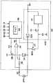
도 4는 도 1에 도시된 구동 제어 유닛(8)의 상세도이다. 마이크로컴퓨터(8A)의 중앙 처리 장치(CPU)(8B)는 후술하는 제어 프로그램에 따라 입력 신호(S1 내지 S5)를 처리하여 제어 출력 신호(CS)를 출력한다. 구동 제어 유닛(8)은 플라이휠 다이오드(8C)와 스위칭 트랜지스터(8D)로 구성되는 구동 회로를 구비한다. 플라이휠 다이오드(8C)와 스위칭 트랜지스터(8D) 사이의 접속점은 타단이 직류 전원(+B)에 연결되어 있는 솔레노이드 비례 제어 밸브(44)의 솔레노이드 코일(44F)의 일단에 검출 레지스터(8E)를 거쳐 연결된다.4 is a detailed view of the
제어 출력 신호(CS)는 펄스 신호에 의해 스위칭 트랜지스터(8D)의 ON/OFF 동작의 듀티비 제어를 행하는 사전 설정된 주파수의 펄스 전압 신호이다. 스위칭 트랜지스터(8D)는 제어 출력 신호(CS)에 응답하여 ON, OFF하여, 제어 출력 신호(CS)에 따른 펄스 전압을 솔레노이드 코일(44F)에 인가한다. 그 결과, 펄스 전압 신호의 듀티비에 따른 구동 전류가 구동 신호(DS)로서 솔레노이드 코일(44F)을 통해 흐른다. 전압 증폭기(8F)는 검출 레지스터(8E)를 통해 흐르는 전류에 의해 만들어지는 전압 신호(Vd)에 응답하여, 솔레노이드 코일(44F)을 통해 흐르는 구동 전류의 순간적인 크기를 나타내는 검출 신호(S6)를 생성하여 마이크로컴퓨터(8A)에 입력한다. The control output signal CS is a pulse voltage signal of a preset frequency which performs duty ratio control of the ON / OFF operation of the switching
입력 신호(S1 내지 S6)에 근거하여 실행되는 솔레노이드 비례 제어 밸브(44)의 구동 제어를 도 5를 참조하여 설명한다. 도 5는, 솔레노이드 비례 제어 밸브(44)를 구동 제어하기 위해 마이크로컴퓨터(8A)에 설치되고 CPU(8B)에 의해 실행되는 제어 프로그램을 나타내는 흐름도이다. 이 제어 프로그램이 개시되어 그의 실행을 시작할 때에, 먼저, 단계 S11에서, 목표 레일 압력(Pt)이 계산된다. 목표 레일 압력(Pt)은 가속기 신호(S5)와 rpm 신호(S3)에 근거하여 계산된다.The drive control of the solenoid
다음으로, 단계 S12에서, 솔레노이드 비례 제어 밸브(44) 내의 연료의 목표 유량(Ft)이 목표 레일 압력(Pt)과 레일 압력 신호(S1)로부터 계산된다. 그 다음에, 단계 S13에서, 목표 유량을 얻는데 필요한 제어 출력 신호(CS)의 목표 듀티비(DTt)가, 목표 유량(Ft)과 검출 신호(S6)로부터 계산된다.Next, in step S12, the target flow rate Ft of the fuel in the solenoid
단계 S14에서, 단계 S13에서 얻어진 목표 듀티비(DTt)가 온도 신호(S4)에 따라 보정되고, 단계 S15에서 단계 S14에서의 보정 결과에 근거하여 통전 듀티비(energization duty ratio)(DTa)가 계산된다.In step S14, the target duty ratio DTt obtained in step S13 is corrected according to the temperature signal S4, and in step S15, an energization duty ratio DTa is calculated based on the correction result in step S14. do.
기본적으로, 통전 듀티비(DTa)에 따라 듀티비가 제어되고 있는 사전 설정된 주파수의 펄스 전압은 제어 출력 신호(CS)로서 출력된다. 그러나, 솔레노이드 비례 제어 밸브(44)의 동작부에서의 동작 마찰로 인해 피스톤(44C)의 움직임에서 히스테리시스가 일어나기 쉬운 경우에, 적절한 시점에서 솔레노이드 코일(44F)에 인가되는 전기 에너지를 일시적으로 증가시켜 제어 출력 신호에 의한 솔레노이드 비례 제어 밸브(44)의 구동력을 순간적으로 상승시킬 수 있도록 하기 위해, 대전류(heavy current)를 솔레노이드 코일(44F)에 투입할 필요가 있는지가 단계 S16에서 판별된다.Basically, the pulse voltage of the preset frequency at which the duty ratio is controlled in accordance with the energizing duty ratio DTa is output as the control output signal CS. However, in the case where hysteresis is likely to occur in the movement of the
단계 S16에서의 판별은 대전류 투입 조건이 존재하는지 아닌지를 판별하는 것이다. 본 실시예에서는, (1) 엔진이 시동하는지, (2) 엔진이 매우 차가운지, (3) 엔진 온도가 높은지, (4) 엔진이 사전 설정된 속도 범위 내에 있는지, (5) 레일 압력의 편차가 사전 설정된 값을 벗어난 상태가 사전 설정된 기간 또는 그 이상 동안 지속되는지에 대한 5개의 각각의 조건에 대하여 판별이 이루어진다. 대전류 투입 조건의 존재는 이런 조건들 중 적어도 하나가 존재할 시에 판별된다. 상태 (1)은 키 스위치 ON 신호(S2)에 근거하여 판별된다. 상태 (2)와 (3)은 온도 신호(S4)에 근거하여 판별된다. 상태 (4)는 rpm 신호(S3)에 근거하여 판별된다. 상태 (5)는 단계 S11에서 얻어진 결과와 레일 압력 신호(S1)로부터 판별된다.The discrimination in step S16 is to discriminate whether or not a large current input condition exists. In this embodiment, (1) the engine is started, (2) the engine is very cold, (3) the engine temperature is high, (4) the engine is within a preset speed range, and (5) the deviation of the rail pressure A determination is made for each of the five conditions as to whether a condition outside of the preset value persists for a preset period or longer. The presence of a high current input condition is determined when at least one of these conditions is present. State (1) is determined based on the key switch ON signal S2. States (2) and (3) are discriminated based on the temperature signal S4. State (4) is determined based on the rpm signal S3. State (5) is discriminated from the result obtained in step S11 and the rail pressure signal S1.
솔레노이드 비례 제어 밸브(44)의 움직임에서 히스테리시스가 일어날 가능성이 낮은 동작 상태하에서는, 단계 S16의 제어 결과는 "아니오"이고 프로그램은 단계 S17로 간다. 여기서, 단계 S15에서 얻어진 통전 듀티비(DTa)에 따른 듀티비로 제어되는 사전 설정된 주파수의 펄스 전압을 제어 출력 신호(CS)로서 출력하는 통상 전류 출력 처리가 실행된다. 스위칭 트랜지스터(8D)는 제어 출력 신호(CS)에 따라 ON, OFF로 되고 그에 따른 펄스 전압은 솔레노이드 코일(44F)에 인가되므로, 통전 듀티비(DTa)에 따른 구동 전류가 구동 신호(DS)로서 솔레노이드 비례 제어 밸브(44)의 솔레노이드 코일(44F)에 펄스적으로 흘러, 솔레노이드 비례 제어 밸브에서의 연료의 유량이 목표 유량(Ft)이 되도록 제어된다.Under the operating state in which the hysteresis is unlikely to occur in the movement of the solenoid
한편, 대전류 투입 조건의 존재가 판별되면, 단계 S16의 결과는 "예"이고 프로그램은 단계 S18로 간다. 단계 S18에서, 대전류 인가에 필요한 파라미터는 레일 압력 신호(S1)에 근거하여 계산된다. 이 계산은 또한 엔진 냉각수 온도를 고려하여 수행될 수도 있다. 대전류의 인가가 각각의 싸이클에서 사전 설정된 시간 동안에 주기적으로 반복되기 때문에, 싸이클당 대전류 인가 기간 p, 싸이클당 대전류 인가 횟수 q, 그리고 반복 주기 r이 계산된다.On the other hand, if the existence of the large current input condition is determined, the result of step S16 is YES and the program goes to step S18. In step S18, the parameters necessary for applying the large current are calculated based on the rail pressure signal S1. This calculation may also be performed taking into account the engine coolant temperature. Since the application of the large current is repeated periodically for a predetermined time in each cycle, the large current application period p per cycle, the number of application of the large current per cycle q, and the repetition period r are calculated.
단계 S19에서, 단계 S15와 단계 S18에서의 계산 결과에 따라, 솔레노이드 비례 제어 밸브(44)의 개폐를, 기본적으로는 통전 듀티비(DTa)에 따라 듀티비가 제어되는 사전 설정된 일정 주파수의 펄스 전압을 사용하여 듀티 제어하면서, 전류 인가 기간 p동안에 대전류를 q회 흘리는 것을 주기 r로 반복하도록 하기 위한 대전류 출력 처리를 실행하고, 그 처리에 따른 제어 출력 신호(CS)가 출력된다.In step S19, according to the calculation result in steps S15 and S18, opening and closing of the solenoid
도 6(a)는 단계 S19의 처리에 의해 얻어지는 제어 출력 신호(CS)의 전압 파형의 예를 나타낸다. 주기 r로 2개의 광폭 펄스 전압이 전류 인가 기간 p에서 반복하여 출력되는 한편, 전류 인가 기간 p 이외의 나머지 기간 s동안에는, 단계 S17에서의 통상 전류 출력 처리에 따른 협폭의 사전 설정된 주파수의 펄스 전압이 단계 S15에서 얻어진 통전 듀티비(DTa)로 출력된다. 전술한 설명으로부터 알 수 있는 바와 같이, 대전류 구동을 위한 광폭 펄스 전압의 펄스폭은 전류 인가 기간 p와 횟수 q에 의해 결정된다.6A shows an example of the voltage waveform of the control output signal CS obtained by the process of step S19. In the period r, two wide pulse voltages are repeatedly output in the current application period p, while for the remaining period s other than the current application period p, the pulse voltage of the narrow predetermined frequency according to the normal current output process in step S17 is It outputs with the energization duty ratio DTa obtained by step S15. As can be seen from the above description, the pulse width of the wide pulse voltage for driving the large current is determined by the current application period p and the number q.
도 6(b)는 도 6(a)에서 나타낸 제어 출력 신호(CS)가 게이트 전압 신호로서 스위칭 트랜지스터(8D)에 인가될 때 구동 신호(DS)의 전류 파형을 나타낸다. 전류 인가 기간 p동안에, 광폭 펄스 전압의 인가 때문에, 스위칭 트랜지스터(8D)가 ON으로 되는 시간이 길어져, 솔레노이드 코일(44F)에 흐르는 전류의 레벨이 커지게 된다. 전류 인가 기간 p동안에 솔레노이드 코일(44F)에 흐르는 전류의 피크값(Wp)은 협폭의 펄스 전압이 기간 s동안에 인가될 때의 전류 피크값(Ws)보다 더 크게 되므로, 전류 인가 기간 p동안에는 기간 s동안에 비하여 더 큰 전기 에너지가 솔레노이드 코일(44F)에 인가되고, 그 결과 보다 큰 구동력으로 솔레노이드 비례 제어 밸브(44)를 구동하게 된다. 즉, 펄스 전압의 펄스폭이 적절한 시점에서 일시적으로 증가되어, 구동 솔레노이드의 구동력을 순간적으로 높게 하는 것이 반복적으로 수행된다.FIG. 6B shows the current waveform of the drive signal DS when the control output signal CS shown in FIG. 6A is applied to the switching
그러므로, 동작 마찰이 솔레노이드 비례 제어 밸브(44)에서 일어날 때에도, 구동력이 전류 인가 기간 p동안에 순간적으로 상승되어서, 솔레노이드 비례 제어 밸브(44)의 피스톤(44C)이, 동작 마찰을 극복하고 순조롭게 동작할 수 있다. 솔레노이드 비례 제어 밸브(44)에 있어서 밸브 장치로서의 응답성의 저하나 제어량의 편차가 발생하는 것을 효과적으로 억제하여 안정된 유량 제어를 할 수 있다.Therefore, even when operating friction occurs in the solenoid
단계 S20에서, 목표 레일 압력(Pt)으로부터 실제 레일 압력(actual rail pressure)(Pa)을 뺌으로써 얻어지는 차이 △P의 절대값이 사전 설정된 값 K보다 작은지에 대한 판별이 이루어진다. 차이 △P의 절대값이 사전 설정된 값 K보다 작으면, 이것은 솔레노이드 비례 제어 밸브(44)가 순조롭게 동작하는 것을 의미한다. 그로한 경우에, 단계 S20에서 판별 결과는 "예"이고 프로그램은 통상 전류 출력 처리를 수행하는 단계 S17로 간다.In step S20, a determination is made whether the absolute value of the difference? P obtained by subtracting the actual rail pressure Pa from the target rail pressure Pt is smaller than the preset value K. If the absolute value of the difference ΔP is less than the preset value K, this means that the solenoid
한편, 차이 △P의 절대값이 사전 설정된 값 K와 같거나 더 크면, 이것은 솔레노이드 비례 제어 밸브(44)가 순조롭게 동작하지 못하고 있어 대전류 출력 처리가 여전히 필요함을 의미한다. 그런 경우에, 단계 S20의 판별 결과는 "아니오"이고 프로그램은 단계 S18로 돌아간다. 단계 S18과 단계 S19의 단계의 실행은 차이 △P의 절대값이 K보다 작게 될 때까지 주기적으로 반복된다. 이와는 달리, 단계 S20의 판별 결과가 "아니오"이면 프로그램은 단계 S19로 돌아가도록 구성할 수도 있다.On the other hand, if the absolute value of the difference [Delta] P is equal to or greater than the preset value K, this means that the solenoid
도 5에서 나타낸 제어에서는, 차이 △P가 사전 설정된 값보다 작게 될 때까지 단계 S18에서 결정되는 파라미터에 따라 대전류 출력 처리를 반복한다. 하지만, 대신에, 대전류 출력 처리의 개시 후 사전 설정된 시간의 경과 후에도 차이 △P가 사전 설정된 값 K보다 더 작게 되지 않을 경우에는, 단계 S18에서 결정되는 파라미터를 변경하여 더 큰 전기 에너지를 인가하도록 구성할 수도 있다.In the control shown in Fig. 5, the large current output process is repeated in accordance with the parameter determined in step S18 until the difference? P becomes smaller than the preset value. However, instead, if the difference ΔP does not become smaller than the preset value K even after the lapse of the preset time after the start of the high current output processing, the parameter determined in step S18 is changed to apply more electric energy. You may.
도 7은 그러한 제어의 실시예에 대한 주요한 부분의 흐름도이며, 이것은 도 5의 단계 S18~단계 S20을 대체하는 것이다.FIG. 7 is a flow chart of the main parts of an embodiment of such control, which replaces steps S18 to S20 of FIG.
도 7에서, 단계 S21, 단계 S22는 각기 단계 S18, 단계 S19에 대응한다. 타이머는 단계 S23에서 시작하고, 타이머의 값 T가 사전 설정된 값 M보다 크거나 같은지가 단계 S24에서 판별된다. 그리고, T<M, 즉, 판별 결과가 "아니오"이면, 프로그램은 단계 S25로 간다. 단계 S25는 도 7에서 단계 S20과 대응되고 그 단계에서는 판별 결과가 "예"이면, 프로그램은 단계 S17로 간다. 단계 S25의 판별 결과가 "아니오"이면, 프로그램은 단계 S21로 돌아가 단계 S21 내지 단계 S25의 실행을 반복한다.In Fig. 7, step S21 and step S22 correspond to step S18 and step S19, respectively. The timer starts at step S23, and it is determined at step S24 whether the value T of the timer is greater than or equal to the preset value M. And if T <M, that is, the determination result is "no", the program goes to step S25. Step S25 corresponds to step S20 in FIG. 7, and if the determination result is "Yes" in the step, the program goes to step S17. If the determination result of step S25 is NO, the program returns to step S21 to repeat the execution of steps S21 to S25.
단계 S25에서 판별 결과가 "예"로 되지 않는 동안은, T가 M보다 크거나 같으면(T≥M) 단계 S24의 판별 결과가 "예"로 되고 프로그램은 단계 S26으로 간다. 단계 S26에서, 단계 S21에서 계산된 파라미터의 경우보다도 더 큰 전기 에너지가 인가되도록 파라미터가 계산된다. 예를 들어, 파라미터 p, q, r 중에 p와 q의 값을 증가함으로써, 전류 인가 기간 p가 연장되고 전류 인가 횟수 q를 증가되도록 파라미터를 적절히 변경한다.While the determination result in step S25 does not become YES, if T is greater than or equal to M (T? M), the determination result in step S24 becomes YES and the program goes to step S26. In step S26, the parameter is calculated so that greater electrical energy is applied than in the case of the parameter calculated in step S21. For example, by increasing the values of p and q in the parameters p, q and r, the parameters are appropriately changed so that the current application period p is extended and the number of times of the current application is increased.
단계 S27에서, 대전류 출력 처리는 단계 S26에서 계산된 파라미터에 따라 실행된다. 단계 S27에서의 처리는 각각의 전류 인가 기간 p동안에 솔레노이드 코일(44F)에 인가되는 전기 에너지의 크기가 단계 S22의 경우보다 더 크게 된다는 것을 제외하고, 기본적으로 단계 S22와 같다.In step S27, the high current output process is executed in accordance with the parameter calculated in step S26. The processing in step S27 is basically the same as step S22 except that the amount of electrical energy applied to the
단계 S28에서, 목표 레일 압력(Pt)으로부터 실제 레일 압력(Pa)을 뺌으로써 얻어지는 차이 △P의 절대값이 사전 설정된 값 K보다 작은지에 대한 판별이 이루어진다. 차이 △P의 절대값이 사전 설정된 값 K보다 작을 때에, 이것은 솔레노이드 비례 제어 밸브(44)가 순조롭게 동작하고 있음을 의미한다. 그런 경우에, 단계 S28에서 판별 결과가 "예"가 되고 프로그램은 단계 S17로 가서 통상 전류 출력 처리를 행한다.In step S28, a determination is made as to whether the absolute value of the difference? P obtained by subtracting the actual rail pressure Pa from the target rail pressure Pt is smaller than the preset value K. When the absolute value of the difference ΔP is smaller than the preset value K, this means that the solenoid
한편, 차이 △P의 절대값이 사전 설정된 값 K보다 크거나 같을 때에, 이것은 솔레노이드 비례 제어 밸브(44)가 순조롭게 동작하지 못하고 있어 대전류 출력 처리가 여전히 필요함을 의미한다. 그런 경우에, 단계 S28에서의 판별 결과는 "아니오"로 되고, 프로그램은 단계 S26으로 진행한다. 차이 △P의 절대값이 K보다 작게될 때까지 단계 S26 및 S27의 실행이 반복된다. 이와는 달리, 단계 S28에서 판별 결과가 "아니오"이면 프로그램이 단계 S27로 되돌아가도록 구성할 수 있다.On the other hand, when the absolute value of the difference [Delta] P is greater than or equal to the preset value K, this means that the solenoid
도 7에 나타낸 구성에 의하면, 단계 S21에서 계산된 파라미터에 따른 대전류 출력 처리가 일정한 기간 동안에 지속되어도 효과가 없는 경우에 더 큰 전기 에너지를 사용함으로써, 솔레노이드 비례 제어 밸브(44)의 순조로운 동작을 실현한다. 그 결과, 솔레노이드 비례 제어 밸브(44)에 부담을 주는 일 없이 솔레노이드 비례 제어 밸브의 순조로운 동작을 가능하게 할 수 있다.According to the configuration shown in Fig. 7, the smooth operation of the solenoid
도 4에서 도시된 회로 구성이 로우측 스위치(low-side switch)로서 스위칭 트랜지스터(8D)를 사용하고 있지만, 대신에 하이측 스위치(high-side switch)로서 스위칭 트랜지스터(8D)를 사용할 수도 있다.Although the circuit configuration shown in FIG. 4 uses the switching
도 8은 하이측 스위치로서 스위칭 트랜지스터(8D)를 사용하는 경우의 회로도를 나타낸다. 도 4에서 부분에 대응하는 도 8에서 나타낸 구동 제어 유닛(81) 중, 도 4에 대응하는 부분에는 도 4와 동일한 참조 부호를 부여한다.8 shows a circuit diagram in the case of using the switching
도 1에서 나타낸 실시예에서, 대전류 출력 처리는 솔레노이드 코일(44F)에 인가된 전압의 레벨은 변경하지 않고, 솔레노이드 코일(44F)에 전압을 인가하는 시간 폭을 크게 하여, 사전 설정된 전류 인가 기간 p동안에 솔레노이드 코일(44F)을 통해 흐르는 전류의 피크값(Wp)이 피크값(Ws)보다 더 크게 되도록 한다. 하지만, 전압 인가의 시간 폭을 변경하는 것 없이 솔레노이드 코일(44A)에 인가되는 전압의 레벨을 크게 함으로써 솔레노이드 코일(44A)에 인가되는 전기 에너지를 크게 하는, 대전류 출력 처리를 위한 구성을 채택할 수도 있다.In the embodiment shown in Fig. 1, the high current output process does not change the level of the voltage applied to the
도 9는 그러한 구성에서 사용되는 회로 설계를 갖는 구동 제어 유닛(82)의 회로도이다. 구동 제어 유닛(82)에서, 구동 제어 유닛(8)의 부분과 동일한 부분은 구동 제어 유닛(8)에서의 그것들과 동일한 참조 부호가 부여된다. 82A는 전원 전압(+B)보다 높은 직류 전압(VH)을 출력하는 승압 회로이고, 82B는 전원 전압(+B) 혹은 직류 전압(VH) 중 어느 하나를 선택하여 솔레노이드 코일(44F)에 인가하기 위한 스위치이다. 스위치(82B)는 마이크로컴퓨터(8A)로부터 제어 신호(S7)에 따라 개폐된다. 직류 전압(VH)은 스위치(82B)가 열려있을 때에 솔레노이드 코일(44F)에 인가된다. 스위치(82B)가 닫혀있을 때는, 다이오드(82C)가 역바이어스된 상태에 놓이고 전원 전압(B+)은 솔레노이드 코일(44F)에 인가된다.9 is a circuit diagram of a
도 10은 도 9에 나타낸 구동 제어 유닛(82)을 사용하는 경우에 실행되는 제어 프로그램을 나타내는 흐름도이다. 도 5에서 나타낸 흐름도의 단계와 동일한 도 10에 나타낸 흐름도의 단계에는 도 5와 동일한 참조 부호를 부여하고 그에 대한 설명을 생략한다. 도 10에서 나타낸 흐름도는 대전류 인가를 위한 파라미터를 계산하는 단계 S31만이 도 5의 흐름도와 다르다.10 is a flowchart showing a control program executed when the
단계 S16에서의 제어 결과가 "예"일 때에, 프로그램은 단계 S31로 가고, 여기서 파라미터들 중 전류 인가 기간 p와 인가 횟수 q가 결정된다. 여기서, 펄스 전압을 구성하는 제어 출력 신호(CSa)는 그 주기가 일정하고 고전압(VH)으로 솔레노이드 코일(44F)을 구동하는 횟수 q를 결정함으로써, 전류 인가 기간 p가 자동적으로 결정된다. 전류 인가 기간 p동안에, 스위치 제어 신호(S7)가 출력되어 스위치(82B)가 열리도록 제어가 실행된다.When the control result in step S16 is YES, the program goes to step S31, where the current application period p and the number of application q of parameters are determined. Here, the period of the control output signal CSa constituting the pulse voltage is constant and the current application period p is automatically determined by determining the number q of driving the
도 11(a)는 단계 S19의 처리에 의해 얻어지는 제어 출력 신호(CSa)의 전압 파형의 예를 나타낸다. q=4인 경우, 즉, 4개 펄스가 각각의 전류 인가 기간 p에서 출력되는 경우가 설명된다. 전류 인가 기간 p동안에, 스위치(82b)가 스위치 제어 신호(S7)에 의해 열려지고 고전압(VH)이 솔레노이드 코일(44F)에 인가된다.Fig. 11A shows an example of the voltage waveform of the control output signal CSa obtained by the process of step S19. The case where q = 4, that is, the case where four pulses are output in each current application period p is described. During the current application period p, the switch 82b is opened by the switch control signal S7 and the high voltage VH is applied to the
도 11(b)는 도 11(a)에 나타낸 제어 출력 신호(CSa)가 게이트 전압 신호로서 스위칭 트랜지스터(8D)에 인가될 때에 구동 신호(DSa)의 전류 파형을 나타낸다. 고전압(VH)의 인가 때문에, 전류 인가 기간 p동안에 스위칭 트랜지스터(8D)의 ON 시간은 주기 s동안의 경우와 같지만, 솔레노이드 코일(44F)을 통해 흐르는 전류의 피크값은 커진다. 주기 s동안보다 전류 인가 기간 p동안에 보다 많은 전기 에너지가 솔레노이드 코일(44F)에 인가되므로, 솔레노이드 비례 제어 밸브(44)는 보다 큰 구동력으로 구동된다. 한편, 펄스 전압의 펄스폭은 적절한 시점에서 일시적으로 증가되어 구동 솔레노이드의 구동력을 순간적으로 높이는 것을 반복적으로 수행한다.FIG. 11B shows the current waveform of the drive signal DSa when the control output signal CSa shown in FIG. 11A is applied to the switching
도 12는 도 9에 나타낸 구동 제어 유닛(82)의 변형 예를 나타낸다. 도 9에 대응되는 도 12의 부분들에는 도 9와 동일한 참조 부호가 부여된다. 도 12에 나타낸 구동 제어 유닛(83)은, 고전압 출력 회로(83A)로부터의 고전압(VH)을 스위치(83B)를 거쳐 솔레노이드 코일(44F)로 인가하고 전원 전압(+B)을 다이오드(83C)를 거쳐 솔레노이드 코일(44F)에 인가하도록 구성된다. 따라서, 스위치(83B)가 열려있을 때에 전원 전압(+B)이 솔레노이드 코일(44F)에 인가된다. 스위치(83B)가 닫혀있을 때, 다이오드(83C)는 역바이어스된 상태에 놓이고 고전압(VH)이 솔레노이드 코일(44F)에 인가된다. 따라서, 이 경우에, 스위치(83B)는 스위치 제어 신호(S7)에 의해, 전류 인가 기간 p동안에만 닫혀지도록 제어된다.FIG. 12 shows a modification of the
도 13은 도 9에 나타낸 구동 제어 유닛(82)의 다른 변형 예를 나타낸다. 도 9에 대응되는 도 13의 부분들에는 도 9와 동일한 참조 부호가 부여된다. 구동 제어 유닛(8C)에서는, 솔레노이드 코일(44F)에 인가되는 전압을 스위치(84B)에 의해 스위치하는데 필요한 다이오드(84C)가 플라이휠 다이오드(8C)와 스위칭 트랜지스터(8D) 사이에 마련된다. 스위치(84B)가 열려 있을 때, 고전압(VH)은 다이오드(84C)를 거쳐 솔레노이드 코일(44F)에 인가되고, 스위치(84B)가 닫혀 있을 때, 다이오드(84C)가 역바이어스된 상태에 놓이고 전원 전압(+B)이 솔레노이드 코일(44F)에 인가된다. 따라서, 이 경우에, 스위치(84B)는 스위치 제어 신호(S7)에 의해, 전류 인가 기간 p동안에만 열려 있도록 제어된다.FIG. 13 shows another modified example of the
도 14는 도 9에 나타낸 구동 제어 유닛(82)의 다른 변형 예를 나타낸다. 도 9에 대응되는 도 14의 부분들에는 도 9와 동일한 참조 부호를 부여한다. 구동 제어 유닛(85)에서는, 솔레노이드 코일(44F)에 인가되는 전압을 스위치(85B)에 의해 스위치하는데 필요한 다이오드(85C)가 플라이휠 다이오드(8C)와 스위칭 트랜지스터(8D) 사이에 마련된다. 스위치(85B)가 열려 있을 때, 전원 전압(+B)이 솔레노이드 코일(44F)에 인가되고, 스위치(85B)가 닫혀 있을 때, 다이오드(84C)가 역바이어스된 상태에 놓이고 고전압(VH)이 솔레노이드 코일(44F)에 인가된다. 따라서, 이 경우에, 스위치(85B)는 스위치 제어 신호(S7)에 의해 전류 인가 기간 p동안에만 닫히도록 제어된다.FIG. 14 shows another modified example of the
전술한 실시예들은 모두 커먼 레일 시스템 펌프의 유량 제어에 적용하는 경우에 대하여 설명하였다. 그러나, 본 발명은 상기 실시예들에 한정되는 것이 아니지만, 다른 목적으로 사용되는 다양한 유체의 유량 제어에 사용되는 솔레노이드 비례의 밸브에도 마찬가지로 적용할 수 있고, 마찬가지의 효과가 얻어지는 것은 물론이다.
The above embodiments have all been described in the case of applying to the flow rate control of the common rail system pump. However, the present invention is not limited to the above embodiments, but can be similarly applied to solenoid proportional valves used for flow rate control of various fluids used for other purposes, and the same effect is naturally obtained.
본 발명에 따라, 정적 또는 동적 마찰은 커먼 레일 시스템 펌프의 유량 제어에 사용되는 솔레노이드 비례 제어 밸브의 실린더와 피스톤 사이에서 일어나면, 적절한 시점에서 그 구동 솔레노이드의 코일에 인가되는 전기 에너지를 일시적으로 증가함으로써 이들 마찰을 극복하여 피스톤이 움직일 수 있도록 할 수 있다. 따라서, 밸브 장치로서의 응답성의 저하, 유량 편차 및 다른 문제들의 발생이 효과적으로 최소화되어, 안정된 유량 제어가 가능하게 된다.According to the invention, static or dynamic friction occurs between the cylinder and the piston of a solenoid proportional control valve used for flow control of a common rail system pump, by temporarily increasing the electrical energy applied to the coil of the drive solenoid at a suitable time. These frictions can be overcome to allow the piston to move. Thus, the occurrence of a decrease in the responsiveness, flow rate variation and other problems as the valve device is effectively minimized, thereby enabling stable flow rate control.
본 발명은 적절한 시점에서 코일에 인가되는 전기 에너지를 일시적으로 증가시키도록 구성되므로, 초기의 구동 단계부터 코일에 대전류를 연속적으로 흘리는 통상적인 방법과 비교하여 전원 소비를 낮출 수 있다. 게다가, 대전류의 연속적인 인가를 견뎌낼 수 있도록 전기적 정격을 올릴 필요가 없기 때문에, 솔레노이드측 혹은 구동측의 어디에서도 비용이 증가되지 않는다.Since the present invention is configured to temporarily increase the electrical energy applied to the coil at a suitable time, the power consumption can be lowered as compared to the conventional method of continuously flowing a large current through the coil from the initial driving stage. In addition, since there is no need to increase the electrical rating to withstand the continuous application of large currents, the cost does not increase either on the solenoid side or on the drive side.
상술한 바와 같이, 본 발명에 따른 유량 제어용 솔레노이드 비례 제어 밸브의 구동 방법 및 장치는, 유량 제어에 사용되는 솔레노이드 비례 제어 밸브의 피스톤과 실린더 사이에서 마찰이 발생하여도 안정한 유량 제어를 가능하게 하여, 유량 제어에 사용되는 솔레노이드 비례 제어 밸브를 구동하는 개선된 방법 및 장치를 제공할 수 있다.As described above, the method and apparatus for driving the solenoid proportional control valve for flow rate control according to the present invention enables stable flow rate control even when friction occurs between the piston and the cylinder of the solenoid proportional control valve used for the flow rate control. An improved method and apparatus for driving solenoid proportional control valves used for flow control can be provided.
Claims (17)
Translated fromKoreanApplications Claiming Priority (2)
| Application Number | Priority Date | Filing Date | Title |
|---|---|---|---|
| JP2001333237AJP3851140B2 (en) | 2001-10-30 | 2001-10-30 | Driving method of electromagnetic proportional control valve for flow control |
| JPJP-P-2001-00333237 | 2001-10-30 |
Publications (2)
| Publication Number | Publication Date |
|---|---|
| KR20050040845A KR20050040845A (en) | 2005-05-03 |
| KR100582314B1true KR100582314B1 (en) | 2006-05-22 |
Family
ID=19148538
Family Applications (1)
| Application Number | Title | Priority Date | Filing Date |
|---|---|---|---|
| KR1020047006482AExpired - Fee RelatedKR100582314B1 (en) | 2001-10-30 | 2002-10-29 | Method and apparatus for driving flow control electromagnetic proportional control valve |
Country Status (7)
| Country | Link |
|---|---|
| US (1) | US7387289B2 (en) |
| EP (1) | EP1441162B1 (en) |
| JP (1) | JP3851140B2 (en) |
| KR (1) | KR100582314B1 (en) |
| CN (1) | CN100353109C (en) |
| DE (1) | DE60224298T2 (en) |
| WO (1) | WO2003038324A1 (en) |
Cited By (1)
| Publication number | Priority date | Publication date | Assignee | Title |
|---|---|---|---|---|
| KR101286400B1 (en)* | 2011-11-16 | 2013-07-15 | 한국기초과학지원연구원 | Large gas injection valve for controlling high-current pulsed power supply |
Families Citing this family (19)
| Publication number | Priority date | Publication date | Assignee | Title |
|---|---|---|---|---|
| JP4692813B2 (en) | 2005-05-13 | 2011-06-01 | Smc株式会社 | Solenoid valve drive control device |
| DE102005029138B3 (en)* | 2005-06-23 | 2006-12-07 | Mtu Friedrichshafen Gmbh | Control and regulating process for engine with common rail system has second actual rail pressure determined by second filter |
| JP4686679B2 (en)* | 2005-12-27 | 2011-05-25 | Smc株式会社 | Solenoid valve drive control device |
| JP4605129B2 (en)* | 2006-09-19 | 2011-01-05 | 株式会社デンソー | Fuel pressure control device |
| JP4780051B2 (en)* | 2007-07-09 | 2011-09-28 | 株式会社デンソー | Fuel injection device for internal combustion engine |
| JP2009030740A (en)* | 2007-07-27 | 2009-02-12 | Bosch Corp | Control method and device for flow control solenoid proportional control valve |
| WO2009075276A1 (en) | 2007-12-11 | 2009-06-18 | Bosch Corporation | Method for controlling drive of flow control valve of common-rail fuel injection controller and common-rail fuel injection controller |
| JP5215831B2 (en)* | 2008-12-08 | 2013-06-19 | Ckd株式会社 | Pressure control device and flow rate control device |
| DE102008054512B4 (en)* | 2008-12-11 | 2021-08-05 | Robert Bosch Gmbh | Method for operating a fuel injection system of an internal combustion engine |
| US7942349B1 (en) | 2009-03-24 | 2011-05-17 | Meyer Andrew E | Fuel injector |
| US8408516B2 (en)* | 2009-04-27 | 2013-04-02 | GM Global Technology Operations LLC | Fluid pressure control device with integrated pressure sensor |
| DE102012017501A1 (en)* | 2012-09-05 | 2014-03-06 | Astrium Gmbh | Device for controlling pressure and / or mass flow for a space propulsion system |
| DE102013201576A1 (en)* | 2013-01-31 | 2014-07-31 | Robert Bosch Gmbh | Method for checking the plausibility of a rail pressure sensor value |
| CN104421477A (en)* | 2013-09-03 | 2015-03-18 | 北京谊安医疗系统股份有限公司 | Proportional valve control device used for anesthesia machine |
| DE102014206231A1 (en)* | 2014-04-02 | 2015-10-08 | Continental Automotive Gmbh | Method for operating a high-pressure pump of an injection system and injection system |
| CN104532782B (en)* | 2014-12-22 | 2016-01-20 | 河海大学 | Flood discharge control method in the dam-break experiments of a kind of unrestrained top and control system |
| JP6589614B2 (en)* | 2015-12-10 | 2019-10-16 | 株式会社デンソー | Electronic control device and transmission system |
| CN105889603B (en)* | 2016-05-20 | 2018-02-06 | 合肥工业大学 | A kind of PWM control methods for improving high-speed switch electromagnetic valve proportionality |
| CN106195395A (en)* | 2016-08-31 | 2016-12-07 | 佛山市云米电器科技有限公司 | The electrically-controlled valve of pulsed operation and control method thereof |
Family Cites Families (23)
| Publication number | Priority date | Publication date | Assignee | Title |
|---|---|---|---|---|
| JPS5582302A (en)* | 1978-12-18 | 1980-06-21 | Nippon Denso Co Ltd | Duty ratio control method of solenoid valve |
| US4345737A (en)* | 1979-03-06 | 1982-08-24 | Nippon Soken, Inc. | Linear solenoid valve actuation device |
| JPS59103091A (en)* | 1982-12-01 | 1984-06-14 | Nippon Denso Co Ltd | Control method of electrification current for solenoid valve |
| US4766921A (en)* | 1986-10-17 | 1988-08-30 | Moog Inc. | Method of operating a PWM solenoid valve |
| JP2690734B2 (en) | 1987-09-16 | 1997-12-17 | 株式会社デンソー | Variable discharge high pressure pump |
| US4949215A (en)* | 1988-08-26 | 1990-08-14 | Borg-Warner Automotive, Inc. | Driver for high speed solenoid actuator |
| US4974622A (en) | 1990-01-23 | 1990-12-04 | Borg-Warner Automotive, Inc. | Self compensation for duty cycle control |
| JP3245718B2 (en)* | 1992-03-26 | 2002-01-15 | 株式会社ボッシュオートモーティブシステム | Fuel injection device |
| EP0563760B2 (en) | 1992-03-26 | 1999-05-12 | Zexel Corporation | Fuel-injection device |
| DE19508445B4 (en)* | 1995-03-09 | 2004-07-08 | Deutz Ag | Fuel injection device for a self-igniting internal combustion engine |
| US5812355A (en) | 1995-09-25 | 1998-09-22 | Nordson Corporation | Electric gun driver |
| JPH09277063A (en)* | 1996-04-18 | 1997-10-28 | Miyachi Technos Corp | Resistance welding controller |
| GB2314901B (en)* | 1996-07-02 | 2001-02-14 | Luk Getriebe Systeme Gmbh | Fluid-operated regulating apparatus and method of using the same |
| DE19723931A1 (en)* | 1997-06-06 | 1998-12-10 | Siemens Ag | Device for controlling an electromechanical actuator |
| DE29715925U1 (en)* | 1997-09-05 | 1997-10-23 | Festo AG & Co, 73734 Esslingen | Circuit device |
| JP3152200B2 (en)* | 1998-02-06 | 2001-04-03 | 株式会社豊田自動織機製作所 | Solenoid valve control device for industrial vehicles |
| US6031707A (en)* | 1998-02-23 | 2000-02-29 | Cummins Engine Company, Inc. | Method and apparatus for control of current rise time during multiple fuel injection events |
| JPH11270428A (en)* | 1998-03-24 | 1999-10-05 | Zexel:Kk | Cylinder injection device |
| JP3855447B2 (en)* | 1998-03-31 | 2006-12-13 | いすゞ自動車株式会社 | Engine fuel injection control device |
| JP4093696B2 (en)* | 1999-02-25 | 2008-06-04 | 株式会社日本自動車部品総合研究所 | Depressurization regulating valve for fuel injection device |
| JP4206563B2 (en)* | 1999-06-18 | 2009-01-14 | 株式会社デンソー | Fuel injection device |
| JP2001152940A (en)* | 1999-11-24 | 2001-06-05 | Mitsubishi Electric Corp | Fuel injection system |
| CN2448976Y (en)* | 2000-07-30 | 2001-09-19 | 刘顺安 | Electricity liquid ratio reversal valve |
- 2001
- 2001-10-30JPJP2001333237Apatent/JP3851140B2/ennot_activeExpired - Lifetime
- 2002
- 2002-10-29WOPCT/JP2002/011202patent/WO2003038324A1/enactiveIP Right Grant
- 2002-10-29USUS10/494,336patent/US7387289B2/ennot_activeExpired - Lifetime
- 2002-10-29KRKR1020047006482Apatent/KR100582314B1/ennot_activeExpired - Fee Related
- 2002-10-29DEDE60224298Tpatent/DE60224298T2/ennot_activeExpired - Lifetime
- 2002-10-29CNCNB028160924Apatent/CN100353109C/ennot_activeExpired - Fee Related
- 2002-10-29EPEP02802243Apatent/EP1441162B1/ennot_activeExpired - Lifetime
Cited By (1)
| Publication number | Priority date | Publication date | Assignee | Title |
|---|---|---|---|---|
| KR101286400B1 (en)* | 2011-11-16 | 2013-07-15 | 한국기초과학지원연구원 | Large gas injection valve for controlling high-current pulsed power supply |
Also Published As
| Publication number | Publication date |
|---|---|
| CN100353109C (en) | 2007-12-05 |
| CN1543544A (en) | 2004-11-03 |
| KR20050040845A (en) | 2005-05-03 |
| WO2003038324A1 (en) | 2003-05-08 |
| US7387289B2 (en) | 2008-06-17 |
| EP1441162A4 (en) | 2004-12-22 |
| EP1441162A1 (en) | 2004-07-28 |
| EP1441162B1 (en) | 2007-12-26 |
| DE60224298D1 (en) | 2008-02-07 |
| JP3851140B2 (en) | 2006-11-29 |
| JP2003139263A (en) | 2003-05-14 |
| WO2003038324A8 (en) | 2004-05-13 |
| US20050151103A1 (en) | 2005-07-14 |
| DE60224298T2 (en) | 2008-12-11 |
Similar Documents
| Publication | Publication Date | Title |
|---|---|---|
| KR100582314B1 (en) | Method and apparatus for driving flow control electromagnetic proportional control valve | |
| US6394414B1 (en) | Electronic control circuit | |
| US6367452B1 (en) | Fuel injection system | |
| EP1429013B1 (en) | Common rail fuel injection control device | |
| EP2547909B1 (en) | Dosing pump with control device of the piston stroke | |
| US7275522B2 (en) | Method and apparatus for controlling a valve, and method and apparatus for controlling a pump-nozzle apparatus with the valve | |
| CN107120461B (en) | Gas valve and method for actuating the same | |
| GB2310540A (en) | Controlling armature movement in an electromagnetic device | |
| US6234122B1 (en) | Method for driving an electromagnetic actuator for operating a gas change valve | |
| KR970001931A (en) | Fuel supply device for internal combustion engine and method of controlling the same | |
| KR20040044892A (en) | Accumulator-type fuel injection device | |
| KR20130119934A (en) | Method for determining the opening point in time of a fuel injector | |
| KR100282831B1 (en) | Fuel injection timing control system of fuel injection pump for diesel engine | |
| JP4363280B2 (en) | Fuel injection device | |
| JPH0735005A (en) | Method and apparatus for driving electromagnetic load | |
| BR102018075240A2 (en) | CONTROL PUMP FOR FUEL PUMP AND CONTROL METHOD FOR THE SAME | |
| KR19990028999A (en) | Control method and control device of solenoid valve | |
| US20050115543A1 (en) | High-pressure fuel pump for an internal combustion engine | |
| US11442478B2 (en) | Pressure control device | |
| KR20190057142A (en) | Operation of fuel injector with hydraulic stop function | |
| KR20150023270A (en) | Method for operating a fuel system for an internal combustion engine | |
| JPH0421063B2 (en) | ||
| JP2009030740A (en) | Control method and device for flow control solenoid proportional control valve | |
| JP2004278411A (en) | Drive device for solenoid valve for internal combustion engine | |
| WO2023228666A1 (en) | Control device and method for controlling an injector |
Legal Events
| Date | Code | Title | Description |
|---|---|---|---|
| A201 | Request for examination | ||
| PA0105 | International application | St.27 status event code:A-0-1-A10-A15-nap-PA0105 | |
| PA0201 | Request for examination | St.27 status event code:A-1-2-D10-D11-exm-PA0201 | |
| PG1501 | Laying open of application | St.27 status event code:A-1-1-Q10-Q12-nap-PG1501 | |
| PN2301 | Change of applicant | St.27 status event code:A-3-3-R10-R13-asn-PN2301 St.27 status event code:A-3-3-R10-R11-asn-PN2301 | |
| R18-X000 | Changes to party contact information recorded | St.27 status event code:A-3-3-R10-R18-oth-X000 | |
| R18-X000 | Changes to party contact information recorded | St.27 status event code:A-3-3-R10-R18-oth-X000 | |
| E902 | Notification of reason for refusal | ||
| PE0902 | Notice of grounds for rejection | St.27 status event code:A-1-2-D10-D21-exm-PE0902 | |
| P11-X000 | Amendment of application requested | St.27 status event code:A-2-2-P10-P11-nap-X000 | |
| P13-X000 | Application amended | St.27 status event code:A-2-2-P10-P13-nap-X000 | |
| E701 | Decision to grant or registration of patent right | ||
| PE0701 | Decision of registration | St.27 status event code:A-1-2-D10-D22-exm-PE0701 | |
| PR1002 | Payment of registration fee | St.27 status event code:A-2-2-U10-U12-oth-PR1002 Fee payment year number:1 | |
| GRNT | Written decision to grant | ||
| PR0701 | Registration of establishment | St.27 status event code:A-2-4-F10-F11-exm-PR0701 | |
| PG1601 | Publication of registration | St.27 status event code:A-4-4-Q10-Q13-nap-PG1601 | |
| FPAY | Annual fee payment | Payment date:20090508 Year of fee payment:4 | |
| PR1001 | Payment of annual fee | St.27 status event code:A-4-4-U10-U11-oth-PR1001 Fee payment year number:4 | |
| LAPS | Lapse due to unpaid annual fee | ||
| PC1903 | Unpaid annual fee | St.27 status event code:A-4-4-U10-U13-oth-PC1903 Not in force date:20100516 Payment event data comment text:Termination Category : DEFAULT_OF_REGISTRATION_FEE | |
| PC1903 | Unpaid annual fee | St.27 status event code:N-4-6-H10-H13-oth-PC1903 Ip right cessation event data comment text:Termination Category : DEFAULT_OF_REGISTRATION_FEE Not in force date:20100516 |