KR100580639B1 - Fluorescence Detector for Microfluidic Detection - Google Patents
Fluorescence Detector for Microfluidic DetectionDownload PDFInfo
- Publication number
- KR100580639B1 KR100580639B1KR1020030100621AKR20030100621AKR100580639B1KR 100580639 B1KR100580639 B1KR 100580639B1KR 1020030100621 AKR1020030100621 AKR 1020030100621AKR 20030100621 AKR20030100621 AKR 20030100621AKR 100580639 B1KR100580639 B1KR 100580639B1
- Authority
- KR
- South Korea
- Prior art keywords
- detector
- microchamber
- excitation light
- fluorescent
- fluorescence
- Prior art date
- Legal status (The legal status is an assumption and is not a legal conclusion. Google has not performed a legal analysis and makes no representation as to the accuracy of the status listed.)
- Expired - Fee Related
Links
Images


Classifications
- G—PHYSICS
- G01—MEASURING; TESTING
- G01N—INVESTIGATING OR ANALYSING MATERIALS BY DETERMINING THEIR CHEMICAL OR PHYSICAL PROPERTIES
- G01N21/00—Investigating or analysing materials by the use of optical means, i.e. using sub-millimetre waves, infrared, visible or ultraviolet light
- G01N21/62—Systems in which the material investigated is excited whereby it emits light or causes a change in wavelength of the incident light
- G01N21/63—Systems in which the material investigated is excited whereby it emits light or causes a change in wavelength of the incident light optically excited
- G01N21/64—Fluorescence; Phosphorescence
- G01N21/645—Specially adapted constructive features of fluorimeters
- G01N2021/6482—Sample cells, cuvettes
Landscapes
- Health & Medical Sciences (AREA)
- Nuclear Medicine, Radiotherapy & Molecular Imaging (AREA)
- Physics & Mathematics (AREA)
- Life Sciences & Earth Sciences (AREA)
- Chemical & Material Sciences (AREA)
- Analytical Chemistry (AREA)
- Biochemistry (AREA)
- General Health & Medical Sciences (AREA)
- General Physics & Mathematics (AREA)
- Immunology (AREA)
- Pathology (AREA)
- Investigating, Analyzing Materials By Fluorescence Or Luminescence (AREA)
- Investigating Or Analysing Materials By The Use Of Chemical Reactions (AREA)
- Measuring Or Testing Involving Enzymes Or Micro-Organisms (AREA)
- Optical Measuring Cells (AREA)
- Apparatus Associated With Microorganisms And Enzymes (AREA)
Abstract
Translated fromKoreanDescription
Translated fromKorean도 1은 본 발명의 바람직한 실시예에 따른 미세유체 검출을 위한 형광검출기에 사용되는 미세유체 칩을 설명하기 위한 사시도를 도시한다.1 is a perspective view illustrating a microfluidic chip used in a fluorescence detector for microfluidic detection according to a preferred embodiment of the present invention.
도 2는 본 발명의 바람직한 실시예에 따른 미세유체 검출을 위한 형광검출기를 설명하기 위한 개략적인 도면을 도시한다.2 is a schematic diagram illustrating a fluorescence detector for microfluidic detection according to a preferred embodiment of the present invention.
도 3은 본 발명의 바람직한 다른 실시예에 따른 형광검출기를 설명하기 위한 개략적인 도면을 도시한다.Figure 3 shows a schematic diagram for explaining a fluorescence detector according to another preferred embodiment of the present invention.
도 4a는 DNA 증폭 반응을 실시간으로 관찰하기 위한 장치에서 시간에 따른 반응온도 프로파일을 도시하는 그래프이다.Figure 4a is a graph showing the reaction temperature profile over time in the device for observing the DNA amplification reaction in real time.
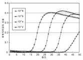
도 4b는 DNA 증폭 반응을 본 발명의 바람직한 실시예에 따른 형광검출기를 이용하여 형광신호를 실시간으로 검출한 결과를 도시하는 그래프이다.Figure 4b is a graph showing the result of detecting the fluorescent signal in real time using a fluorescence detector according to a preferred embodiment of the present invention DNA amplification reaction.
도 5는 미세유체 칩 내에서 DNA가 온도를 상승시킴에 따라 DNA 멜팅(melting)으로 인하여 형광이 감소되는 것을 형광검출기로 측정한 결과를 도시하는 그래프이다.FIG. 5 is a graph showing the result of measuring by fluorescence detector that fluorescence is reduced due to DNA melting (melting) of DNA in the microfluidic chip.
<도면의 주요 부분에 대한 부호의 설명><Explanation of symbols for the main parts of the drawings>
100: 미세유체 칩102: 마이크로 히터100: microfluidic chip 102: micro heater
103: 마이크로 채널105: 마이크로 챔버103: micro channel 105: micro chamber
106: 시료 유입구108: 시료 배출구106: sample inlet 108: sample outlet
110: 상부 기판 112: 하부 기판110: upper substrate 112: lower substrate
200, 300: 형광 검출기202, 302: 광원200, 300:
204, 236: 제 1 및 제 2 렌즈206, 234: 제 1 및 제 2 필터204 and 236: first and
208, 232: 제 1 및 제 2 미러210, 310: 대물렌즈208, 232: first and
220, 320: 미세유체 칩 240: 포토다이오드220, 320: microfluidic chip 240: photodiode
242, 342, 346: 활성영역242, 342, 346: active area
304, 336, 338: 제 1 내지 제 3 렌즈304, 336, 338: first to third lenses
306, 307, 309: 제 1 내지 제 3 필터306, 307, and 309: first to third filters
308, 311: 제 1 및 제 2 미러340, 344: 제 1 및 제 2 포토다이오드308, 311: first and
본 발명은 미세유체 공학(microfluidics)에 관한 것으로서, 보다 상세하게는 미세유체 소자 내에서 미세유체의 반응을 실시간으로 검출할 수 있는 초소형 형광검출기에 관한 것이다.BACKGROUND OF THE INVENTION 1. Field of the Invention The present invention relates to microfluidics, and more particularly, to a microfluorescence detector capable of detecting in real time the reaction of microfluidics in a microfluidic device.
미세유체 칩은 포토리소그래피나 고온-엠보싱(hot-embossing), 몰딩 등의 미세가공 기술로 만들어진 미세채널 구조에 덮개를 덮어 미량의 유체를 보관(contain)하거나 조절(manipulate)할 수 있도록 한 칩으로 소모되는 시약의 양 을 줄이고 분석시간을 짧게 할 수 있다는 장점을 가지고 있다.Microfluidic chips are microchips made of micromachining techniques such as photolithography, hot-embossing, and molding to cover and cover or control a small amount of fluid. This has the advantage of reducing the amount of reagent consumed and shortening the analysis time.
특히, 중합효소 연쇄반응(PCR; polymerase chain reaction)과 같이 DNA 변성(denaturation), 어닐링(annealing) 및 연장(extension) 반응에서 각각이 서로 다른 온도를 요구하는 경우에 온도 사이클을 반복적으로 수행하여 반응을 시키게 되는데, 이러한 경우 적은 반응 부피와 넓은 면적은 마이크로 챔버 내에 온도가 빠르게 전달되도록 하여 온도사이클에 요구되는 시간을 줄일 수 있다.In particular, in the case of DNA denaturation, annealing and extension reactions such as polymerase chain reaction (PCR), each of which requires a different temperature, the temperature cycle is repeatedly performed. In this case, the small reaction volume and the large area allow the temperature to be quickly transferred into the microchamber, thereby reducing the time required for the temperature cycle.
PCR 반응을 실시간으로 검출하는 방법으로는 여러 가지가 가능하지만 현재 대부분의 경우 형광검출법을 사용한다. 이때 사용되는 방법은 PCR 반응으로 생성된 이중 나선(double stranded) DNA에 결합(binding)하여 형광이 향상시키는 SYBR Green I등의 다이(dye)를 이용하는 방법, PCR에 사용되는 프라이머(primer) 이외에 두 프라이머 사이에 결합할 수 있는 DNA 시퀀스(sequence)를 프로브(probe)로 사용하고 이 프로브 양 끝에 형광단(fluorophore)과 발광억제단(quencher)을 결합시켜 DNA 합성에 사용되는 태그 폴리머라제(Taq polymerase)의 엑소뉴클레아제 활성(exonuclease activity)을 사용하여 프로브가 잘리면서 형광단과 발광억제단 사이에 결합된 DNA가 잘리면서 형광단과 발광억제단 사이의 결합이 절단되면서 형광이 나오는 것을 분석하는 TaqMan(R) 방법 등 다양한 방법이 개발되어있다.There are many ways to detect PCR reactions in real time, but most of them use fluorescence detection. The method used here is a method using a die such as SYBR Green I which binds to a double stranded DNA generated by a PCR reaction to improve fluorescence, and in addition to the primer used for PCR, Taq polymerase used for DNA synthesis by using a DNA sequence capable of binding between primers as a probe and binding a fluorophore and a quencher to both ends of the probe. TaqMan (analysis of fluorescence as the probe is cut and the DNA bound between the fluorophore and the luminescent inhibitor is cut and the bond between the fluorophore and the luminescent inhibitor is cleaved using the exonuclease activity of R) Various methods have been developed.
이러한 형광 검출법 중의 하나로서, Applied Biosystems사에 의하여 1999년 7월 27일 "SYSTEM FOR REAL TIME DETECTION OF NUCLEIC ACID AMPLIFICATION PRODUCTS"라는 명칭으로 특허 허여된 미합중국특허 제 5.928,907 호에 개시된 방법은 광섬유를 이용하여 튜브 내의 형광을 검출하는 방법을 채용하고 있다. 이 경우 다수의 튜브를 하나의 검출기로 검출할 수 있다는 점에서는 유리하지만 광섬유에 형광을 여기시키기 위한 여기광을 집광시키기 위해서는 레이저와 같이 간섭성이 뛰어난 고가의 광원을 사용해야 하며 또한 정밀한 광학장치가 필요하여 가격이 비싸진다는 단점이 있다.As one of such fluorescence detection methods, the method disclosed in U.S. Patent No. 5.928,907, entitled "SYSTEM FOR REAL TIME DETECTION OF NUCLEIC ACID AMPLIFICATION PRODUCTS" by Applied Biosystems on July 27, 1999, uses an optical fiber. To detect fluorescence in the tube. In this case, it is advantageous in that many tubes can be detected by one detector. However, in order to focus the excitation light for exciting the fluorescence in the optical fiber, an expensive coherent light source such as a laser is required, and precise optics are required. There is a disadvantage that the price is expensive.
한편, Cepheid사에 의하여 2002년 4월 9일 "MULTI-CHANNEL OPTICAL DETECTION SYSTEM"이라는 명칭으로 특허 허여된 미합중국특허 제 6,369,893 호에 개시된 방법은 여기 블록(excitation block)과 검출 블록(detection block)을 나누어 구성하였으며, LED를 이용한 여기 블록으로 형광을 여기시키고 90℃로 위치한 검출 블록으로 형광 신호를 검출하도록 되어 모듈화에 유리하다는 장점을 가지고 있다.Meanwhile, the method disclosed in U.S. Patent No. 6,369,893, issued by Cepheid on April 9, 2002 under the name "MULTI-CHANNEL OPTICAL DETECTION SYSTEM", divides the excitation block and the detection block. The excitation block using the LED is used to excite the fluorescence, and the detection block located at 90 ° C. detects the fluorescence signal.
하지만, 여기와 검출을 90℃ 각도를 가지고 수행하기 위해서는 튜브를 마름모꼴로 하여 벽면쪽에서 여기와 검출이 이루어지므로 충분한 벽면 두께를 필요로 하기 때문에 시료의 체적(sample volume)이 25 ㎕ 이상이 되어야 하는 단점이 있다.However, in order to perform excitation and detection at an angle of 90 ° C, since the excitation and detection are performed on the wall with a rhombic tube, a sufficient wall thickness is required, so that the sample volume must be 25 μl or more. There is this.
본 발명은 상기한 바와 같은 문제점을 개선하기 위하여 창출된 것으로서, 미세유체 칩의 소정 체적을 가지는 마이크로 챔버 내에서 일어나는 미세유체의 반응을 실시간으로 검출할 수 있는 초소형 형광 검출기에 관한 것이다.The present invention has been made to solve the above problems, and relates to a microfluorescence detector capable of detecting in real time a reaction of microfluids occurring in a microchamber having a predetermined volume of a microfluidic chip.
본 발명의 한 유형에 따르면, 소정의 체적을 갖는 마이크로 챔버를 구비하는 미세유체 칩 내에서 반응하는 PCR 증폭을 실시간으로 측정하기 위한 형광 검출기에 있어서, 여기광을 발생하는 광원과, 여기광이 소정의 스폿 사이즈를 가지고 마이크로 챔버에 조사될 수 있도록 구성된 제 1 광학계와, 제 1 검출기 및 소정의 스폿 사이즈를 가지는 여기광에 의하여 마이크로 챔버 내에서 유도된 형광빔을 제 1 검출기로 반사시키는 제 2 광학계를 포함하는 형광 검출기가 제공된다.According to one type of the present invention, in a fluorescent detector for measuring in real time PCR amplification reacting in a microfluidic chip having a microchamber having a predetermined volume, a light source for generating excitation light and an excitation light are predetermined; A first optical system configured to be irradiated to the microchamber with a spot size of and a second optical system for reflecting, to the first detector, a fluorescent beam induced in the microchamber by the first detector and excitation light having a predetermined spot size There is provided a fluorescence detector comprising a.
본 발명의 또 다른 유형에 의하면, 제 1 광학계가 여기광의 단파장 성분을 투과시키는 제 1 필터와, 광원과 제 1 필터 사이에 배치되어 여기광을 집광하기 위한 제 1 렌즈와, 제 1 필터를 통과한 여기광의 소정 성분의 파장을 투과시키며 마이크로 챔버 내에서 유도된 형광빔을 반사시키는 제 1 미러 및 제 1 미러를 투과한 여기광을 소정의 스폿 사이즈를 갖도록 하는 대물렌즈를 포함하는 형광 검출기가 제공된다.According to another type of the invention, a first optical system passes through a first filter for transmitting short wavelength components of excitation light, a first lens disposed between the light source and the first filter for condensing excitation light, and a first filter. Provided is a fluorescence detector comprising a first mirror that transmits a wavelength of a predetermined component of an excitation light and reflects a fluorescence beam induced in a microchamber, and an objective lens having an excitation light transmitted through the first mirror having a predetermined spot size. do.
또한, 본 발명의 바람직한 실시예에 따르면, 여기광은 제 1 렌즈에 의하여 대물렌즈의 전방에 초점(F)이 맺히도록 집광되는 것을 특징으로 한다.Further, according to a preferred embodiment of the present invention, the excitation light is focused by the first lens so as to focus on the front of the objective lens.
또한, 본 발명의 다른 유형에 의하면, 제 2 광학계는 제 1 미러로부터 반사된 형광빔을 제 1 검출기로 반사하기 위한 제 2 미러와, 형광빔의 장파장 성분을 투과시키는 제 2 필터 및 제 2 필터를 투과한 형광빔을 제 1 검출기로 집속하기 위한 제 2 렌즈를 포함하는 형광 검출기가 제공된다.Further, according to another type of the present invention, the second optical system includes a second mirror for reflecting the fluorescent beam reflected from the first mirror to the first detector, a second filter and a second filter for transmitting the long wavelength component of the fluorescent beam. There is provided a fluorescence detector comprising a second lens for focusing a fluorescence beam transmitted through the first detector.
또한, 본 발명의 바람직한 실시예에 따르면, 제 1 미러가 제 1 면 및 제 2 면을 구비하며, 제 1 면에 여기광을 투과하고 형광빔을 반사하는 코팅이 형성되어 있고, 제 2 면에는 여기광과 형광빔에 대하여 투명한 것을 특징으로 한다.In addition, according to a preferred embodiment of the present invention, the first mirror has a first side and a second side, the first side is formed with a coating for transmitting excitation light and reflecting the fluorescent beam, the second side It is characterized by being transparent to the excitation light and the fluorescent beam.
또한, 본 발명의 바람직한 실시예에 따르면, 제 1 미러가 제 1 면 및 제 2 면을 구비하며, 제 1 면에 여기광을 투과하는 코팅이 형성되어 있고, 제 2 면에는 여기광을 투과하고 형광빔을 반사하는 코팅이 형성되어 있는 것을 특징으로 한다.Further, according to a preferred embodiment of the present invention, the first mirror has a first side and a second side, the first side is formed with a coating for transmitting the excitation light, the second side transmits the excitation light It is characterized in that a coating is formed which reflects the fluorescent beam.
또한, 본 발명의 바람직한 실시예에 따르면, 제 2 미러는 형광빔 중 제 1 파장을 가지는 형광빔 부분을 반사하고 제 2 파장을 가지는 형광빔 부분은 투과하는 것을 특징으로 한다.Further, according to a preferred embodiment of the present invention, the second mirror is characterized in that the fluorescent beam portion having a first wavelength of the fluorescent beam reflects and the fluorescent beam portion having a second wavelength is transmitted.
또한, 본 발명의 바람직한 실시예에 따르면, 마이크로 챔버 내에 PCR 반응 중 형광빔을 발생시키기 위한 다이(dye)로서 SYBR 그린 I을 첨가하는 것을 특징으로 한다.In addition, according to a preferred embodiment of the present invention, SYBR Green I is added as a die for generating a fluorescent beam during a PCR reaction in the microchamber.
또한, 본 발명의 바람직한 실시예에 따르면, SYBR 그린 I은 B-형 간염 바이러스를 인코딩(encoding)한 DNA의 PCR 증폭을 실시간으로 모니터링하기 위하여 첨가되는 것을 특징으로 한다.In addition, according to a preferred embodiment of the present invention, SYBR Green I is characterized in that it is added to monitor the PCR amplification of the DNA encoding the hepatitis B virus (real).
또한, 본 발명의 바람직한 실시예에 따르면, 형광빔이 2가지 이상의 파장을 가지도록 마이크로 챔버 내에 적어도 2 이상의 다이(dye)를 첨가하는 것을 특징으로 한다.In addition, according to a preferred embodiment of the present invention, at least two dies are added to the microchamber so that the fluorescent beam has two or more wavelengths.
이하, 첨부된 도면들을 참조하면서 본 발명의 바람직한 실시예에 따른 미세유체 칩 및 미세유체 칩을 이용하여 미세유체의 반응을 검출하기 위한 형광검출기를 상세히 설명하기로 한다.Hereinafter, a fluorescence detector for detecting a reaction of a microfluid using a microfluidic chip and a microfluidic chip according to a preferred embodiment of the present invention will be described in detail with reference to the accompanying drawings.
도 1에 도시한 바와 같이, 미세유체 칩(100)은 시료 유입구(106)와 시료 배출구(108)를 구비하는 상부기판(110) 및 하부 기판(112)을 포함한다. 반응(reaction) 온도를 조절하기 위하여 하부 기판(112)에 마이크로 히터(102)가 결합된다. 또한, 상부 또는 하부 기판(110, 112)에 마이크로 챔버(105)와 시료 유입구(106), 시료 배출구(108) 및 시료 배출구(108)에 연결되는 마이크로 채널(104)을 포토리소그라피, 고온-엠보싱 또는 플라스틱 몰드와 같은 방법을 이용하여 형성한다.As shown in FIG. 1, the
상부와 하부 기판(110, 112)은 애노딕 본딩(anodic bonding)이나 열적 본딩, 접착제를 이용한 본딩 등으로 접합시켜 내부에 유체가 보관될 수 있도록 형성한다. 미세유체 칩(100)은 실리콘 표면에 금속을 패터닝한 마이크로 히터(102)를 하부에 접촉시켜 온도를 제어할 수 있다. 온도 전달이 용이하도록 하부 기판(112)은 실리콘, 메탈 또는 열전도 효율이 높은 플라스틱 재질을 사용하여 형성하는 것이 바람직하다. 또한, 상부 기판(110)은 형광검출이 용이하도록 유리, 투명한 플라스틱 등의 투명한 재질을 사용하는 것이 바람직하다.The upper and
마이크로 챔버(104)는 실제 검출되는 미세유체 칩(100)의 중앙 부분이 시료 유입구(106)와 시료 배출구(108) 부분보다 폭이 넓게 되어있어 유입된 시료에 대하여 검출되는 부피가 최대화될 수 있도록 한다. 본 발명의 바람직한 실시예에서 미세유체 칩(100)의 중앙부분에 형성되는 마이크로 챔버(105)의 폭은 1 mm 이상으로 제작하였다.The microchamber 104 has a central portion of the
도 2는 본 발명의 바람직한 실시예에 따른 형광검출기를 설명하기 위한 개략적인 도면을 도시한다.Figure 2 shows a schematic diagram for explaining a fluorescence detector according to a preferred embodiment of the present invention.
도 2에 도시한 본 발명의 바람직한 실시예에 따른 형광검출기(200)는 발광 다이오드와 같은 광원(202), 제 1 및 제 2 렌즈(204, 236), 제 1 및 제 2 필터(206, 234), 제 1 및 제 2 미러(208, 232), 대물렌즈(210), 미세유체 칩(220) 및 활성영역(242)을 갖는 포토 다이오드(240)를 포함한다.The
광원(202)으로부터 발생된 빛은 제 1 렌즈(204)에 의하여 대물렌즈(210)의 전방에 초점(F)이 맺히도록 집광되며, 광원(202)으로부터 발생된 빛이 형광에 간섭을 줄 수 있는 장파장 성분을 제거하기 위하여 제 1 렌즈(204)와 초점(F) 사이에 제 1 필터(206)를 배치한다. 본 발명의 바람직한 실시예에 따른 제 1 필터(206)는 여기빔(excitation beam) 통과 필터(pass filter)로 칭하며 단파장을 통과시키는 필터나 밴드패스 필터를 사용하였다.The light generated from the
제 1 필터(206)를 통과한 빛은 제 1 필터(206)와 대물렌즈(210) 사이에 배치되는 제 1 미러(208)에 의하여 소정 성분의 파장을 갖는 빛을 대물렌즈(210)로 투과시키고, 반면 나머지 성분의 파장을 갖는 빛은 제 2 미러(232)의 반대 방향으로 반사시킴으로써 나머지 성분의 파장을 갖는 여기빔이 미세유체 칩(220)으로 입사하지 않도록 한다. 본 발명의 바람직한 실시예에서, 제 1 미러(208)는 다이크로익 미러로 형성하였다.The light passing through the
제 1 미러(208)를 투과한 여기빔은 대물렌즈(220)에 의하여 미세유체 칩(220)의 마이크로 챔버로 소정의 스폿 사이즈(spot size)를 가지고 조사된다. 이때, 본 발명의 바람직한 실시예에 따르면, 대물렌즈(220)를 적절하게 선택하여 사용함으로써 마이크로 챔버의 폭보다 큰 1 mm 이상으로 마이크로 채널에 입사되는 빛의 스폿 사이즈를 조절할 수 있다.The excitation beam transmitted through the
따라서, 본 발명의 바람직한 실시예에 따르면, 여기빔의 스폿 사이즈를 조절하여 마이크로 챔버의 전체에 여기빔이 조사되도록 함으로써, 미세유체 칩(220)으로부터 발생되는 형광을 보다 효율적으로 검출할 수 있는 특징을 갖는다.Therefore, according to a preferred embodiment of the present invention, by adjusting the spot size of the excitation beam so that the excitation beam is irradiated to the entire micro chamber, it is possible to more efficiently detect the fluorescence generated from the
본 발명의 바람직한 실시예에 따르면, 미세유체 칩의 마이크로 챔버 내에서 일어나는 중합효소 연쇄반응(PCR; polymerase chain reaction)의 형광검출 신호를 보기 위하여 다음과 같이 하였다.According to a preferred embodiment of the present invention, the fluorescence detection signal of the polymerase chain reaction (PCR) occurring in the microchamber of the microfluidic chip was as follows.
실시예 1Example 1
타겟(target) DNA의 초기 농도로부터 B-형 간염 바이러스를 인코딩(encoding)한 DNA의 PCR 증폭을 실시간으로 모니터링하기 위한 형광빔을 검출하기 위한 PCR의 마스터 혼합물의 조성은 하기의 표 1과 같다.The composition of the master mixture of PCR for detecting the fluorescence beam for real-time monitoring of PCR amplification of DNA encoding the hepatitis B virus from the initial concentration of the target DNA is shown in Table 1 below.

표 1에 따라 준비된 PCR 용액 중 1 ㎕를 도 1에 도시한 미세유체 칩(100)의 시료 유입구(106)에 주입함으로써 마이크로 채널(103)을 통하여 마이크로 챔버(105)내로 시료가 유입될 수 있었다.1 μl of the PCR solution prepared according to Table 1 was injected into the
이어서, 미세유체 칩(100)의 마이크로 챔버(105)에 형광 검출기를 정렬시킨 후, 도 4a에 도시한 바와 같은 온도 프로파일을 이용하여 마이크로 히터(102)를 가열하였으며, 하기의 표 2에 기재된 PCR 온도 조건에 따라 열주기(thermal cycling)를 변화시키면서 실험을 진행하였다.Subsequently, after aligning the fluorescence detector in the

도 4b는 DNA 증폭 반응을 본 발명의 바람직한 실시예에 따른 형광검출기를 이용하여 형광신호를 실시간으로 검출한 결과를 도시하는 그래프이다.Figure 4b is a graph showing the result of detecting the fluorescent signal in real time using a fluorescence detector according to a preferred embodiment of the present invention DNA amplification reaction.
도 4b에 도시한 바와 같이, 그래프의 DNA 플라스미드(plasmid)의 복제 수에 따른 열적 주기동안 실시간으로 포토 다이오드에서 측정된 형광빔의 값을 나타내고 있다. 즉, 어닐링 구간에서 8초간 지연 후에 5초간 형광빔을 연속 측정하여 PCR 주기 수에 대해 표시한 그래프이다.As shown in FIG. 4B, the graph shows the value of the fluorescence beam measured in the photodiode in real time during the thermal cycle according to the number of copies of the DNA plasmid. That is, the graph shows the number of PCR cycles by continuously measuring the fluorescence beam for 5 seconds after an 8 second delay in the annealing section.
도 4b에 도시한 그래프에 따르면, PCR 반응은 그 원리에 따라 DNA 양이 기하급수적으로 증가하는데 검출한계 이하에서는 검출되지 않고 직선으로 방출되다가 검출 한계 이상으로 DNA가 증폭되면 주기에 따라 형광빔이 기하급수적으로 증가하여 형광빔이 검출되기 시작함을 알 수 있다.According to the graph shown in FIG. 4B, the PCR reaction is exponentially increased in the amount of DNA according to the principle, but is not detected below the detection limit, but is emitted in a straight line. It can be seen that the fluorescence beam starts to be detected by increasing in series.
그리고, 반응할 dNTP의 농도가 떨어지게 되는 특정 주기 이후에는 반응 속도가 감소하기 시작하면서 형광빔 증가율이 감소하여 PCR 반응의 전형적인 S자 곡선 을 보여준다. 최초 DNA 플라스미드의 복제 수가 증가함에 따라 기하급수적으로 증가하기 시작하는 주기가 줄어듦을 알 수 있다.In addition, after a certain period in which the concentration of dNTP to be reacted decreases, the reaction rate begins to decrease, and the fluorescence beam growth rate decreases to show a typical S curve of the PCR reaction. It can be seen that as the number of copies of the original DNA plasmid increases, the cycle of increasing exponential decreases.
실시예 2Example 2
SYBR 그린 Ⅰ을 이용해서 실시간 PCR 반응을 검출한 신호의 경우 PCR로 증폭된 DNA가 원하는 부위인지 여부를 확인하기 위하여 DNA 변성(denaturation)을 일으키는 멜팅(melting) 커브를 그릴 필요가 있다.In the case of a signal detecting a real-time PCR reaction using SYBR Green I, it is necessary to draw a melting curve that causes DNA denaturation to determine whether the DNA amplified by PCR is a desired site.
도 5는 미세유체 칩 내에서 DNA가 온도를 상승시킴에 따라 DNA 멜팅(melting)으로 인하여 형광이 감소되는 것을 형광검출기로 측정한 결과를 도시하는 그래프이다.FIG. 5 is a graph showing the result of measuring by fluorescence detector that fluorescence is reduced due to DNA melting (melting) of DNA in the microfluidic chip.
도 5에 도시한 바와 같이, 증폭이된 이중 나선(double strand)의 DNA가 온도를 올려주면서 실시간으로 형광을 검출하면 이중 나선과 달리 온도에 따라 풀려서 단일 가닥 형태의 DNA로 바뀌면서 형광신호가 감소함을 알 수 있다. 따라서, 이러한 신호를 분석하여 얻을 수 있는 정보는 DNA의 멜팅 온도이고 이로부터 PCR로 증폭된 DNA의 이중 나선의 길이를 알 수 있게 된다.As shown in FIG. 5, when the amplified double strand DNA detects fluorescence in real time while raising the temperature, the fluorescence signal decreases as the double strand is released and changed into a single stranded DNA unlike the double helix. It can be seen. Therefore, the information that can be obtained by analyzing such a signal is the melting temperature of the DNA and from this it is possible to know the length of the double helix of the DNA amplified by PCR.
하기의 표 3은 멜팅 곡선을 얻기 위하여 실험한 조건을 기재한 것이다.Table 3 below describes the conditions tested to obtain the melting curve.

다시, 도 2를 참조하면, 본 발명의 바람직한 실시예에 따르면, 마이크로 채 널 내의 시료는 광원(202)으로부터 발생된 여기광에 의해 형광을 내고 이 형광빔은 대물렌즈(210)로 입사된 후 집속됨으로써 선택된다. 이때 선택된 형광빔은 제 1 미러(208)에 의하여 제 2 미러(232)로 반사된 후, 다시 제 2 미러(232)에 의하여 제 2 필터(234)로 반사된다.Referring back to FIG. 2, in accordance with a preferred embodiment of the present invention, the sample in the microchannel fluoresces by the excitation light generated from the
본 발명의 바람직한 실시예에 따르면, 제 2 필터(234)는 형광빔 투과필터로서 장파장 성분을 통과시키는 필터 또는 밴드패스 필터를 사용하였다.According to a preferred embodiment of the present invention, the
그리고 나서, 제 2 렌즈(236)는 제 2 필터(234)를 투과한 형광빔을 포토 다이오드(240)의 활성영역(242)으로 집속시킴으로써 전기적 신호를 검출하게 된다.Then, the
도 3은 본 발명의 바람직한 다른 실시예에 따른 형광 검출기를 설명하기 위한 개략적인 도면을 도시한다.Figure 3 shows a schematic diagram for explaining a fluorescence detector according to another preferred embodiment of the present invention.
도 3에 도시한 본 발명의 바람직한 다른 실시예에 따른 형광 검출기(300)는 광원(302), 제 1 내지 제 3 렌즈(304, 336, 338), 제 1 내지 제 3 필터(306, 307, 309), 제 1 및 제 2 미러(308, 311), 제 1 및 제 2 포토 다이오드(340, 344), 대물렌즈(310) 및 미세유체 칩(320)을 포함한다.According to another exemplary embodiment of the present invention illustrated in FIG. 3, the
도 2를 참조하여 설명한 형광 검출기(200)가 하나의 형광빔을 검출하도록 설계되어진 반면에 도 3에 도시한 형광 검출기(300)는 동시에 2개 이상의 형광빔을 검출할 수 있도록 구성되었다는 점에서 상이하다.While the
예를 들면, 본 발명의 바람직한 실시예에서 B-형 간염의 바이러스 유전인자를 인코딩한 DNA를 검출하기 위하여 SYBR 그린 Ⅰ 다이를 사용하였지만, 그 밖의 다른 유전 형질을 인코딩한 것을 검출하는데 사용되는 다이로서 FAM (carboxyfluorescein)과 TAMRA (carboxytetramethylrhodamine) 등을 동시에 사용하는 경우에 형광 검출기(300)를 적용할 수 있다.For example, in the preferred embodiment of the present invention, a SYBR Green I die was used to detect DNA encoding the viral genetic factor of hepatitis B, but as a die used to detect encoding of other genetic traits, In the case where FAM (carboxyfluorescein) and TAMRA (carboxytetramethylrhodamine) are used at the same time, the
보다 상세하게 설명하면, 본 발명의 바람직한 다른 실시예에 따른 제 1 미러(308)는 두 개 이상의 다이를 사용함으로써 발생되는 서로 다른 파장을 갖는 형광빔을 모두 제 2 미러(311)로 반사시킨다.In more detail, the
제 2 미러(311)는 제 1 파장의 형광빔을 제 2 필터(307) 및 제 2 렌즈(336)를 경유하여 제 1 포토다이오드(340)의 활성영역(342)으로 입사시킨다.The
반면, 제 2 파장의 형광빔은 제 2 미러(311)를 투과한 다음, 제 3 필터(309)를 통과한다. 그리고 나서, 제 3 필터(309)를 통과한 제 2 파장의 형광빔은 제 3 렌즈(338)에 의하여 제 2 포토다이오드(344)의 활성영역(346)에 입사하게 됨으로써, 형광 검출기(300)는 2개 이상의 형광빔을 검출할 수 있게 된다.On the other hand, the fluorescent beam of the second wavelength passes through the
본 발명의 바람직한 실시예에 따르면, 광원(302)은 470 nm 정도를 피크 파장으로 한 청색 LED(light emitting diode)를 사용하였으며, 여기빔 패스 필터로 사용된 제 1 필터(306)는 단파장을 투과시키는 단파장 패스 필터로서 단파장을 가지는 빛을 투과하는 다이크로익 필터(dichroic filter)를 사용하였다.According to a preferred embodiment of the present invention, the
이때, 다이크로익 필터는 투과시키지 않아야 하는 장파장 영역의 빛이 0~1%정도의 투과율을 가지고 투과되기 때문에 후면광(background)을 줄이기 위하여 2장 이상을 사용할 수도 있다.In this case, since the dichroic filter is transmitted with light having a transmittance of about 0 to 1%, the two or more dichroic filters may be used to reduce the background light.
또한, 방사광 패스 필터의 경우에는 여기광이 통과하여 포토 다이오드에 도달하여 검출되어 후면광 신호가 커지는 것을 줄이기 위해 긴 파장을 투과시키는 장 파장 투과 다이크로익 필터를 1장 또는 2장을 사용할 수 있고 별도로 장파장을 투과시키는 색유리 필터(color glass filter)를 추가로 사용할 수도 있다.In addition, in the case of the emission light filter, one or two long wavelength transmission dichroic filters that transmit long wavelengths may be used to reduce excitation light passing through the photodiode and detecting the back light signal. Separately, a color glass filter may be used that transmits long wavelengths.
비록, 본 발명의 바람직한 실시예가 제 1 미러가 제 1 면 및 제 2 면을 구비하며, 제 1 면에 여기광을 투과하고 형광빔을 반사하는 코팅이 형성되어 있고, 제 2 면에는 여기광과 형광빔에 대하여 투명한 것을 특징으로 하는 도면을 참조하여 설명되었지만, 제 1 미러가 제 1 면에 여기광을 투과하는 코팅이 형성되어 있고, 제 2 면에는 여기광을 투과하고 형광빔을 반사하는 코팅이 형성되도록 변형할 수 있다.Although a preferred embodiment of the present invention, the first mirror has a first side and a second side, the first side is formed with a coating for transmitting the excitation light and reflecting the fluorescent beam, the second side and the excitation light Although described with reference to the drawing, which is transparent with respect to the fluorescent beam, a coating is formed in which the first mirror transmits excitation light on the first side, and a coating which transmits the excitation light and reflects the fluorescent beam on the second side. It can be modified to form.
상기한 바와 같이 구성된 본 발명의 바람직한 실시예에 따르면, 광원에서 방출되는 광이 제 1 미러와 대물렌즈 사이에서 포커싱되도록 설계함으로써, 대물렌즈를 통과한 여기빔의 스폿 사이즈를 넓게 형성하여 미세유체 칩의 마이크로 챔버 전체에 여기광을 조사할 수 있어서 보다 넓은 면적에서 형광빔을 검출할 수 있는 효과가 있다.According to a preferred embodiment of the present invention configured as described above, the light emitted from the light source is designed to be focused between the first mirror and the objective lens, thereby forming a spot size of the excitation beam passing through the objective lens to widen the microfluidic chip. The excitation light can be irradiated to the entire microchamber of Hg, so that the fluorescent beam can be detected in a larger area.
따라서, 본 발명의 바람직한 실시예에 따라 형광 검출기를 구성하면, 여기광을 마이크로 챔버에 정렬하기가 용이하고 그밖의 광학부품을 조절하기 위한 기구적 부품을 별도로 필요로 하지 않기 때문에 형광 검출기의 제작 단가를 낮출 수 있는 효과가 있다.Therefore, when the fluorescence detector is constructed in accordance with the preferred embodiment of the present invention, it is easy to align the excitation light to the microchamber and the manufacturing cost of the fluorescence detector is not required because a mechanical component for adjusting other optical components is not required. It has the effect of lowering.
본 발명은 도면에 도시된 실시예를 참고로 설명되었으나, 이는 예시적인 것에 불구하며, 당해 분야에서 통상적인 지식을 가진 자라면 이로부터 다양한 변형 및 균등한 타 실시예가 가능하다는 점을 이해할 것이다. 따라서, 본 발명의 진정한 기술적 보호 범위는 상세한 설명의 범위 내로 정해지는 것이 아니라 첨부된 특허청구범위로 정해져야 할 것이다.Although the present invention has been described with reference to the embodiments shown in the drawings, this is in spite of an example, it will be understood by those skilled in the art that various modifications and equivalent other embodiments are possible. Therefore, the true technical protection scope of the present invention should be determined not by the scope of the detailed description but by the appended claims.
Claims (13)
Translated fromKoreanPriority Applications (7)
| Application Number | Priority Date | Filing Date | Title |
|---|---|---|---|
| KR1020030100621AKR100580639B1 (en) | 2003-12-30 | 2003-12-30 | Fluorescence Detector for Microfluidic Detection |
| EP04020439AEP1550858B1 (en) | 2003-12-30 | 2004-08-27 | System comprising a fluorescence detecting system and microfluid chip with micro chamber |
| DE602004031189TDE602004031189D1 (en) | 2003-12-30 | 2004-08-27 | A system comprising a fluorescence detection system and a micro-fluidic microchip chip |
| US10/933,084US7327459B2 (en) | 2003-12-30 | 2004-09-02 | Fluorescence detector for detecting microfluid |
| CN2004100786523ACN1637407B (en) | 2003-12-30 | 2004-09-14 | Fluorescence detectors for detection of microfluidics |
| JP2004369445AJP2005195582A (en) | 2003-12-30 | 2004-12-21 | Fluorescence detector for microfluidic detection |
| JP2007268238AJP2008116446A (en) | 2003-12-30 | 2007-10-15 | Fluorescence detector for microfluidic detection |
Applications Claiming Priority (1)
| Application Number | Priority Date | Filing Date | Title |
|---|---|---|---|
| KR1020030100621AKR100580639B1 (en) | 2003-12-30 | 2003-12-30 | Fluorescence Detector for Microfluidic Detection |
Publications (2)
| Publication Number | Publication Date |
|---|---|
| KR20050068809A KR20050068809A (en) | 2005-07-05 |
| KR100580639B1true KR100580639B1 (en) | 2006-05-16 |
Family
ID=34567860
Family Applications (1)
| Application Number | Title | Priority Date | Filing Date |
|---|---|---|---|
| KR1020030100621AExpired - Fee RelatedKR100580639B1 (en) | 2003-12-30 | 2003-12-30 | Fluorescence Detector for Microfluidic Detection |
Country Status (6)
| Country | Link |
|---|---|
| US (1) | US7327459B2 (en) |
| EP (1) | EP1550858B1 (en) |
| JP (2) | JP2005195582A (en) |
| KR (1) | KR100580639B1 (en) |
| CN (1) | CN1637407B (en) |
| DE (1) | DE602004031189D1 (en) |
Cited By (5)
| Publication number | Priority date | Publication date | Assignee | Title |
|---|---|---|---|---|
| KR101334183B1 (en) | 2007-06-01 | 2013-12-02 | 삼성전자주식회사 | Fluorescence detecting module for microreaction and fluorescence detecting system having the same |
| KR20190096614A (en) | 2018-02-09 | 2019-08-20 | 단국대학교 천안캠퍼스 산학협력단 | Real-time monitoring device for quantitative nucleic acid measurement using isothermal amplification |
| KR20210145008A (en) | 2020-05-22 | 2021-12-01 | 하이윈 테크놀로지스 코포레이션 | Circulation member for ball screw |
| EP4154981A1 (en) | 2021-09-24 | 2023-03-29 | Nanobiolife Inc. | Multichannel isothermal amplification system and operation method |
| KR20230043438A (en) | 2021-09-24 | 2023-03-31 | 주식회사 나노바이오라이프 | Multu channel isothermal amplification system |
Families Citing this family (30)
| Publication number | Priority date | Publication date | Assignee | Title |
|---|---|---|---|---|
| US8119066B2 (en)* | 2006-02-08 | 2012-02-21 | Molecular Devices, Llc | Multimode reader |
| WO2007124085A2 (en)* | 2006-04-20 | 2007-11-01 | The Regents Of The University Of California | Device for quantification of radioisotope concentrations in a micro-fluidic platform |
| KR100790880B1 (en)* | 2006-07-05 | 2008-01-02 | 삼성전자주식회사 | Microfluidic device comprising a microchannel or microchamber having a hydrophobic porous polymer bound to magnetic beads bonded to a wall and a method of using the same |
| KR101422467B1 (en)* | 2007-02-08 | 2014-07-24 | 삼성전자주식회사 | A system and a method for detecting fluorescence in microfluidic chip |
| WO2008116941A1 (en) | 2007-03-26 | 2008-10-02 | Fundación Gaiker | Method and device for detecting genetic material by means of polymerase chain reaction |
| KR101089045B1 (en) | 2007-06-28 | 2011-12-02 | (주)바이오니아 | Real-time monitoring device of nucleic acid amplification reaction product |
| KR101410752B1 (en)* | 2007-07-20 | 2014-06-23 | 삼성전자 주식회사 | An optical detection device, an optical detection method, and a microfluidic system including the optical detection device |
| EP2198003A4 (en)* | 2007-10-09 | 2018-02-28 | University of Notre Dame du Lac | Microfluidic platforms for multi-target detection |
| KR101022769B1 (en)* | 2008-10-20 | 2011-03-17 | 삼성전자주식회사 | Photodetector for Biochip |
| JP2010284101A (en)* | 2009-06-11 | 2010-12-24 | Hitachi High-Technologies Corp | Reaction vessel, parallel processing device, and sequencer |
| US8535282B2 (en)* | 2009-07-14 | 2013-09-17 | Southwest Research Institute | Wound healing sensor techniques |
| CN101949847B (en)* | 2010-08-13 | 2012-05-30 | 浙江大学 | Lensless fluorescence imaging detection device and application |
| CN102445441B (en)* | 2010-10-09 | 2015-09-30 | 易尚明天科技有限公司 | Large-area fluorescent detector |
| CN102220226B (en)* | 2011-05-23 | 2013-07-24 | 北京工业大学 | Two-path temperature control polymerase chain reactor and real-time detection device |
| CN103376249A (en)* | 2012-04-28 | 2013-10-30 | 易尚明天科技有限公司 | Ultraviolet point fluorescence scanner |
| JP2014020832A (en)* | 2012-07-13 | 2014-02-03 | Hitachi High-Technologies Corp | Flow cell for biological substance analysis and biological substance analysis device |
| AU2013202808B2 (en) | 2012-07-31 | 2014-11-13 | Gen-Probe Incorporated | System and method for performing multiplex thermal melt analysis |
| JP2013061357A (en)* | 2013-01-08 | 2013-04-04 | Shimadzu Corp | Sample cell and particle size distribution measuring apparatus using the same |
| CN103217405B (en)* | 2013-03-21 | 2015-03-04 | 浙江大学 | Microfluidic contrast optical path detection system |
| EP3052236B1 (en) | 2013-09-30 | 2021-07-14 | Bio-Rad Laboratories, Inc. | Microfluidic cartridge device and methods of use and assembly |
| EP3055407B1 (en)* | 2013-10-07 | 2022-01-12 | Agdia Inc. | Optical assembly for use in portable testing device for analyzing biological samples |
| CN106290267A (en)* | 2015-05-18 | 2017-01-04 | 北京怡成生物电子技术股份有限公司 | Fluorescence detection device |
| DE102015209756A1 (en)* | 2015-05-28 | 2016-12-01 | Carl Zeiss Microscopy Gmbh | Arrangement and method for light-sheet microscopy |
| KR102070487B1 (en)* | 2017-02-02 | 2020-01-28 | 명지대학교 산학협력단 | Optical signal detecting system and method using a narrow spectrum filter |
| RU2658600C1 (en)* | 2017-11-20 | 2018-06-21 | Федеральное государственное бюджетное образовательное учреждение высшего образования "Российский национальный исследовательский медицинский университет им. Н.И. Пирогова" Министерства здравоохранения Российской Федерации (ФГБОУ ВО РНИМУ им. Н.И. Пирогова Минздрава России) | Construction of the cartridge working area for carrying out a polymerase chain reaction |
| KR102102773B1 (en)* | 2018-01-12 | 2020-04-21 | 재단법인 오송첨단의료산업진흥재단 | Fluorescence analyzing apparatus based portable micro-optical component |
| US20220274108A1 (en)* | 2019-08-23 | 2022-09-01 | miDiagnostics NV | Multi-color system for real time pcr detection |
| KR102247676B1 (en)* | 2019-09-27 | 2021-05-03 | 주식회사 마하테크 | minute plastic detection apparatus |
| CN113418898B (en)* | 2021-06-18 | 2022-10-28 | 贵州医科大学 | Integrated device of PIFO platform and composed of micro-fluidic chip and fluorescence sensor |
| CN114669338B (en)* | 2022-04-15 | 2023-05-12 | 扬州大学 | Microfluidic chip based on urine detection disease |
Family Cites Families (48)
| Publication number | Priority date | Publication date | Assignee | Title |
|---|---|---|---|---|
| US1684417A (en)* | 1925-04-28 | 1928-09-18 | Harry A Silberman | Dentist's kit and instrument support |
| US2210318A (en)* | 1937-03-23 | 1940-08-06 | Eckert Carl | Apparatus for sterilizing toothpicks or the like |
| US2720702A (en)* | 1954-04-19 | 1955-10-18 | Freedman Hyman | Dental device |
| US4279594A (en)* | 1979-10-18 | 1981-07-21 | Reflek Products, Incorporated | Dental hand mirror |
| US4353694A (en)* | 1980-01-25 | 1982-10-12 | Pelerin Joseph J | Dental kit for performing root canals |
| JPH02271827A (en)* | 1989-04-13 | 1990-11-06 | Aisin Seiki Co Ltd | Reader for fluorescent picture information |
| US5139420A (en)* | 1990-09-04 | 1992-08-18 | Walker William S | Dental mirror system |
| US5228851A (en)* | 1991-10-01 | 1993-07-20 | Burton Clarence E | Single-use disposable prophylactic elastic sleeve |
| JPH05142045A (en) | 1991-11-20 | 1993-06-08 | Shimadzu Corp | Photoluminescence measuring device |
| WO1993022053A1 (en)* | 1992-05-01 | 1993-11-11 | Trustees Of The University Of Pennsylvania | Microfabricated detection structures |
| US5422067A (en)* | 1992-09-15 | 1995-06-06 | Barney; Everett A. | Instrument cassette and method for using the same |
| US5348470A (en)* | 1993-01-29 | 1994-09-20 | Mcgowan Nancy J | Fiber-optic illuminated dental mirror |
| US5538613A (en)* | 1993-10-26 | 1996-07-23 | Genesys Technologies, Inc. | Electrophoresis analyzer |
| AU698953B2 (en) | 1994-04-29 | 1998-11-12 | Applied Biosystems, Llc | System for real time detection of nucleic acid amplification products |
| JP3568626B2 (en) | 1994-05-24 | 2004-09-22 | オリンパス株式会社 | Scanning optical microscope |
| DE69417899T2 (en)* | 1994-11-17 | 1999-11-04 | Chemunex, Maisons-Alfort | Device and method for recognizing and counting rare mammalian cells |
| US5608519A (en)* | 1995-03-20 | 1997-03-04 | Gourley; Paul L. | Laser apparatus and method for microscopic and spectroscopic analysis and processing of biological cells |
| JP3678456B2 (en) | 1995-05-19 | 2005-08-03 | オリンパス株式会社 | Scanning laser microscope equipment |
| US6174677B1 (en)* | 1995-10-13 | 2001-01-16 | Ut-Battelle, Llc | Advanced surface-enhanced Raman gene probe systems and methods thereof |
| JPH09243598A (en) | 1996-03-08 | 1997-09-19 | Shimadzu Corp | Multi-capillary DNA nucleotide sequencer |
| US6369893B1 (en) | 1998-05-19 | 2002-04-09 | Cepheid | Multi-channel optical detection system |
| US5951284A (en)* | 1998-03-10 | 1999-09-14 | Lake; James A. | Intraoral instrument |
| CA2331897C (en) | 1998-05-14 | 2008-11-18 | Luminex Corporation | Multi-analyte diagnostic system and computer implemented process for same |
| US6564940B2 (en)* | 1998-09-30 | 2003-05-20 | The Procter & Gamble Company | Electric toothbrush |
| US6059106A (en)* | 1998-10-21 | 2000-05-09 | Gillette Canada Inc. | Toothbrush display and storage package |
| USD425202S (en)* | 1999-01-21 | 2000-05-16 | Hu-Friedy Mfg. Co., Inc. | Dental instrument handle |
| KR100379411B1 (en)* | 1999-06-28 | 2003-04-10 | 엘지전자 주식회사 | biochip and method for patterning and measuring biomaterial of the same |
| US6206192B1 (en)* | 1999-10-18 | 2001-03-27 | Dendek Dental Products | Dental emergency kit |
| KR100339379B1 (en)* | 1999-10-29 | 2002-06-03 | 구자홍 | biochip and apparatus and method for measuring biomaterial of the same |
| US6206694B1 (en)* | 1999-11-24 | 2001-03-27 | Crystalmark Dental Systems, Inc. | Handpiece assembly for air abrasion |
| TWI220926B (en)* | 2000-03-24 | 2004-09-11 | Ind Tech Res Inst | Sieving apparatus for a bio-chip |
| US6311837B1 (en)* | 2000-03-28 | 2001-11-06 | The Procter & Gamble Company | Packaging arrangement having recesses for preventing a switch from being placed in a continuously-on position |
| CN1198135C (en)* | 2000-04-10 | 2005-04-20 | 财团法人工业技术研究院 | Biochip detection device |
| CN1141399C (en)* | 2000-04-30 | 2004-03-10 | 厦门大学 | Twin introducer used for homogeneous fluorescent PCR testing |
| JP2002131648A (en) | 2000-10-20 | 2002-05-09 | Olympus Optical Co Ltd | Fluorescence microscope |
| US6443729B1 (en)* | 2001-03-29 | 2002-09-03 | Jeffrey A. Watson | Illuminated dental mirror |
| JP2002350732A (en)* | 2001-05-25 | 2002-12-04 | Nikon Corp | Fluorescence observation device |
| CN2514342Y (en)* | 2001-07-12 | 2002-10-02 | 北京清大德人显微数字技术有限公司 | Gene chip detector |
| SE526185C2 (en)* | 2001-11-07 | 2005-07-19 | Prolight Diagnostics Ab | Method and apparatus for immunoassay |
| JP3731882B2 (en) | 2001-11-09 | 2006-01-05 | アイダエンジニアリング株式会社 | Method and apparatus for measuring fluorescence intensity |
| JP4355210B2 (en) | 2001-11-30 | 2009-10-28 | フルイディグム コーポレイション | Microfluidic device and method of using microfluidic device |
| CA2384490A1 (en)* | 2002-05-01 | 2003-11-01 | Carl Parker Associates, Inc. | Dental or surgical illuminated mirror |
| USD468428S1 (en)* | 2002-05-01 | 2003-01-07 | Carl Parker Associates, Inc. | Illuminated dental mirror |
| US7015317B2 (en) | 2002-05-02 | 2006-03-21 | Abbott Laboratories | Polynucleotides for the detection and quantification of hepatitis B virus nucleic acids |
| WO2003098277A2 (en)* | 2002-05-17 | 2003-11-27 | Applera Corporation | Optical instrument including excitation source |
| ATE537438T1 (en) | 2002-05-17 | 2011-12-15 | Life Technologies Corp | DEVICE AND METHOD FOR DISTINGUISHING SEVERAL FLUORESCENCE SIGNALS BASED ON THEIR EXCITATION WAVELENGTH |
| US20030219754A1 (en)* | 2002-05-23 | 2003-11-27 | Oleksy Jerome E. | Fluorescence polarization detection of nucleic acids |
| US7050224B2 (en)* | 2003-11-07 | 2006-05-23 | Olympus Corporation | Fluorescence observing apparatus |
- 2003
- 2003-12-30KRKR1020030100621Apatent/KR100580639B1/ennot_activeExpired - Fee Related
- 2004
- 2004-08-27EPEP04020439Apatent/EP1550858B1/ennot_activeExpired - Lifetime
- 2004-08-27DEDE602004031189Tpatent/DE602004031189D1/ennot_activeExpired - Lifetime
- 2004-09-02USUS10/933,084patent/US7327459B2/ennot_activeExpired - Fee Related
- 2004-09-14CNCN2004100786523Apatent/CN1637407B/ennot_activeExpired - Fee Related
- 2004-12-21JPJP2004369445Apatent/JP2005195582A/enactivePending
- 2007
- 2007-10-15JPJP2007268238Apatent/JP2008116446A/enactivePending
Cited By (6)
| Publication number | Priority date | Publication date | Assignee | Title |
|---|---|---|---|---|
| KR101334183B1 (en) | 2007-06-01 | 2013-12-02 | 삼성전자주식회사 | Fluorescence detecting module for microreaction and fluorescence detecting system having the same |
| KR20190096614A (en) | 2018-02-09 | 2019-08-20 | 단국대학교 천안캠퍼스 산학협력단 | Real-time monitoring device for quantitative nucleic acid measurement using isothermal amplification |
| KR20210145008A (en) | 2020-05-22 | 2021-12-01 | 하이윈 테크놀로지스 코포레이션 | Circulation member for ball screw |
| EP4154981A1 (en) | 2021-09-24 | 2023-03-29 | Nanobiolife Inc. | Multichannel isothermal amplification system and operation method |
| KR20230043438A (en) | 2021-09-24 | 2023-03-31 | 주식회사 나노바이오라이프 | Multu channel isothermal amplification system |
| KR20230043442A (en) | 2021-09-24 | 2023-03-31 | 주식회사 나노바이오라이프 | Multu channel isothermal amplification system |
Also Published As
| Publication number | Publication date |
|---|---|
| KR20050068809A (en) | 2005-07-05 |
| EP1550858B1 (en) | 2011-01-26 |
| CN1637407B (en) | 2010-05-12 |
| US7327459B2 (en) | 2008-02-05 |
| US20050140978A1 (en) | 2005-06-30 |
| JP2008116446A (en) | 2008-05-22 |
| CN1637407A (en) | 2005-07-13 |
| JP2005195582A (en) | 2005-07-21 |
| EP1550858A1 (en) | 2005-07-06 |
| DE602004031189D1 (en) | 2011-03-10 |
Similar Documents
| Publication | Publication Date | Title |
|---|---|---|
| KR100580639B1 (en) | Fluorescence Detector for Microfluidic Detection | |
| US20220040701A1 (en) | Microfluidic analysis system | |
| KR101334183B1 (en) | Fluorescence detecting module for microreaction and fluorescence detecting system having the same | |
| US7670832B2 (en) | System for fluorescence monitoring | |
| JP6234980B2 (en) | Improved method for quantification of forensic DNA | |
| JPH08510562A (en) | Real-time detector for nucleic acid amplification products | |
| US20120214686A1 (en) | Quantitative, Highly Multiplexed Detection of Nucleic Acids | |
| WO1993020240A1 (en) | Method and device for detection of nucleic acid or analyte using total internal reflectance | |
| EP2209555A2 (en) | Detecting and mixing in a conduit in integrated bioanalysis systems | |
| JP3664680B2 (en) | Device for thermal cycling of fluid in a cartridge | |
| US20230333020A1 (en) | A diagnostic device suitable for detection of pathogens, and detection methods using such a device | |
| CN111819276B (en) | Reaction treatment device | |
| KR101890753B1 (en) | Gene analysis device | |
| JP6876162B2 (en) | Reaction processing equipment and reaction processing method |
Legal Events
| Date | Code | Title | Description |
|---|---|---|---|
| A201 | Request for examination | ||
| PA0109 | Patent application | St.27 status event code:A-0-1-A10-A12-nap-PA0109 | |
| PA0201 | Request for examination | St.27 status event code:A-1-2-D10-D11-exm-PA0201 | |
| D13-X000 | Search requested | St.27 status event code:A-1-2-D10-D13-srh-X000 | |
| R17-X000 | Change to representative recorded | St.27 status event code:A-3-3-R10-R17-oth-X000 | |
| PG1501 | Laying open of application | St.27 status event code:A-1-1-Q10-Q12-nap-PG1501 | |
| D14-X000 | Search report completed | St.27 status event code:A-1-2-D10-D14-srh-X000 | |
| PN2301 | Change of applicant | St.27 status event code:A-3-3-R10-R13-asn-PN2301 St.27 status event code:A-3-3-R10-R11-asn-PN2301 | |
| PN2301 | Change of applicant | St.27 status event code:A-3-3-R10-R13-asn-PN2301 St.27 status event code:A-3-3-R10-R11-asn-PN2301 | |
| E902 | Notification of reason for refusal | ||
| PE0902 | Notice of grounds for rejection | St.27 status event code:A-1-2-D10-D21-exm-PE0902 | |
| E13-X000 | Pre-grant limitation requested | St.27 status event code:A-2-3-E10-E13-lim-X000 | |
| P11-X000 | Amendment of application requested | St.27 status event code:A-2-2-P10-P11-nap-X000 | |
| P13-X000 | Application amended | St.27 status event code:A-2-2-P10-P13-nap-X000 | |
| E701 | Decision to grant or registration of patent right | ||
| PE0701 | Decision of registration | St.27 status event code:A-1-2-D10-D22-exm-PE0701 | |
| GRNT | Written decision to grant | ||
| PR0701 | Registration of establishment | St.27 status event code:A-2-4-F10-F11-exm-PR0701 | |
| PR1002 | Payment of registration fee | St.27 status event code:A-2-2-U10-U11-oth-PR1002 Fee payment year number:1 | |
| PG1601 | Publication of registration | St.27 status event code:A-4-4-Q10-Q13-nap-PG1601 | |
| PR1001 | Payment of annual fee | St.27 status event code:A-4-4-U10-U11-oth-PR1001 Fee payment year number:4 | |
| PR1001 | Payment of annual fee | St.27 status event code:A-4-4-U10-U11-oth-PR1001 Fee payment year number:5 | |
| PR1001 | Payment of annual fee | St.27 status event code:A-4-4-U10-U11-oth-PR1001 Fee payment year number:6 | |
| PR1001 | Payment of annual fee | St.27 status event code:A-4-4-U10-U11-oth-PR1001 Fee payment year number:7 | |
| R18-X000 | Changes to party contact information recorded | St.27 status event code:A-5-5-R10-R18-oth-X000 | |
| FPAY | Annual fee payment | Payment date:20130422 Year of fee payment:8 | |
| PR1001 | Payment of annual fee | St.27 status event code:A-4-4-U10-U11-oth-PR1001 Fee payment year number:8 | |
| FPAY | Annual fee payment | Payment date:20140424 Year of fee payment:9 | |
| PR1001 | Payment of annual fee | St.27 status event code:A-4-4-U10-U11-oth-PR1001 Fee payment year number:9 | |
| FPAY | Annual fee payment | Payment date:20150422 Year of fee payment:10 | |
| PR1001 | Payment of annual fee | St.27 status event code:A-4-4-U10-U11-oth-PR1001 Fee payment year number:10 | |
| FPAY | Annual fee payment | Payment date:20160422 Year of fee payment:11 | |
| PR1001 | Payment of annual fee | St.27 status event code:A-4-4-U10-U11-oth-PR1001 Fee payment year number:11 | |
| FPAY | Annual fee payment | Payment date:20170420 Year of fee payment:12 | |
| PR1001 | Payment of annual fee | St.27 status event code:A-4-4-U10-U11-oth-PR1001 Fee payment year number:12 | |
| LAPS | Lapse due to unpaid annual fee | ||
| PC1903 | Unpaid annual fee | St.27 status event code:A-4-4-U10-U13-oth-PC1903 Not in force date:20180510 Payment event data comment text:Termination Category : DEFAULT_OF_REGISTRATION_FEE | |
| PC1903 | Unpaid annual fee | St.27 status event code:N-4-6-H10-H13-oth-PC1903 Ip right cessation event data comment text:Termination Category : DEFAULT_OF_REGISTRATION_FEE Not in force date:20180510 |