KR100580618B1 - Apparatus and method for recognizing user emotion through short time monitoring of physiological signals - Google Patents
Apparatus and method for recognizing user emotion through short time monitoring of physiological signalsDownload PDFInfo
- Publication number
- KR100580618B1 KR100580618B1KR1020020003868AKR20020003868AKR100580618B1KR 100580618 B1KR100580618 B1KR 100580618B1KR 1020020003868 AKR1020020003868 AKR 1020020003868AKR 20020003868 AKR20020003868 AKR 20020003868AKR 100580618 B1KR100580618 B1KR 100580618B1
- Authority
- KR
- South Korea
- Prior art keywords
- signal
- emotion
- user
- heart rate
- feature values
- Prior art date
- Legal status (The legal status is an assumption and is not a legal conclusion. Google has not performed a legal analysis and makes no representation as to the accuracy of the status listed.)
- Expired - Fee Related
Links
Images


Classifications
- A—HUMAN NECESSITIES
- A61—MEDICAL OR VETERINARY SCIENCE; HYGIENE
- A61B—DIAGNOSIS; SURGERY; IDENTIFICATION
- A61B5/00—Measuring for diagnostic purposes; Identification of persons
- A61B5/02—Detecting, measuring or recording for evaluating the cardiovascular system, e.g. pulse, heart rate, blood pressure or blood flow
- A61B5/024—Measuring pulse rate or heart rate
- A61B5/02405—Determining heart rate variability
- A—HUMAN NECESSITIES
- A61—MEDICAL OR VETERINARY SCIENCE; HYGIENE
- A61B—DIAGNOSIS; SURGERY; IDENTIFICATION
- A61B5/00—Measuring for diagnostic purposes; Identification of persons
- A61B5/16—Devices for psychotechnics; Testing reaction times ; Devices for evaluating the psychological state
- A—HUMAN NECESSITIES
- A61—MEDICAL OR VETERINARY SCIENCE; HYGIENE
- A61B—DIAGNOSIS; SURGERY; IDENTIFICATION
- A61B5/00—Measuring for diagnostic purposes; Identification of persons
- A61B5/16—Devices for psychotechnics; Testing reaction times ; Devices for evaluating the psychological state
- A61B5/165—Evaluating the state of mind, e.g. depression, anxiety
- A—HUMAN NECESSITIES
- A61—MEDICAL OR VETERINARY SCIENCE; HYGIENE
- A61B—DIAGNOSIS; SURGERY; IDENTIFICATION
- A61B5/00—Measuring for diagnostic purposes; Identification of persons
- A61B5/72—Signal processing specially adapted for physiological signals or for diagnostic purposes
- A61B5/7235—Details of waveform analysis
- A61B5/7264—Classification of physiological signals or data, e.g. using neural networks, statistical classifiers, expert systems or fuzzy systems
- A—HUMAN NECESSITIES
- A61—MEDICAL OR VETERINARY SCIENCE; HYGIENE
- A61B—DIAGNOSIS; SURGERY; IDENTIFICATION
- A61B5/00—Measuring for diagnostic purposes; Identification of persons
- A61B5/0002—Remote monitoring of patients using telemetry, e.g. transmission of vital signals via a communication network
- A—HUMAN NECESSITIES
- A61—MEDICAL OR VETERINARY SCIENCE; HYGIENE
- A61B—DIAGNOSIS; SURGERY; IDENTIFICATION
- A61B5/00—Measuring for diagnostic purposes; Identification of persons
- A61B5/72—Signal processing specially adapted for physiological signals or for diagnostic purposes
- A61B5/7235—Details of waveform analysis
- A61B5/7264—Classification of physiological signals or data, e.g. using neural networks, statistical classifiers, expert systems or fuzzy systems
- A61B5/7267—Classification of physiological signals or data, e.g. using neural networks, statistical classifiers, expert systems or fuzzy systems involving training the classification device
- G—PHYSICS
- G16—INFORMATION AND COMMUNICATION TECHNOLOGY [ICT] SPECIALLY ADAPTED FOR SPECIFIC APPLICATION FIELDS
- G16H—HEALTHCARE INFORMATICS, i.e. INFORMATION AND COMMUNICATION TECHNOLOGY [ICT] SPECIALLY ADAPTED FOR THE HANDLING OR PROCESSING OF MEDICAL OR HEALTHCARE DATA
- G16H50/00—ICT specially adapted for medical diagnosis, medical simulation or medical data mining; ICT specially adapted for detecting, monitoring or modelling epidemics or pandemics
- G16H50/20—ICT specially adapted for medical diagnosis, medical simulation or medical data mining; ICT specially adapted for detecting, monitoring or modelling epidemics or pandemics for computer-aided diagnosis, e.g. based on medical expert systems
- Y—GENERAL TAGGING OF NEW TECHNOLOGICAL DEVELOPMENTS; GENERAL TAGGING OF CROSS-SECTIONAL TECHNOLOGIES SPANNING OVER SEVERAL SECTIONS OF THE IPC; TECHNICAL SUBJECTS COVERED BY FORMER USPC CROSS-REFERENCE ART COLLECTIONS [XRACs] AND DIGESTS
- Y10—TECHNICAL SUBJECTS COVERED BY FORMER USPC
- Y10S—TECHNICAL SUBJECTS COVERED BY FORMER USPC CROSS-REFERENCE ART COLLECTIONS [XRACs] AND DIGESTS
- Y10S128/00—Surgery
- Y10S128/92—Computer assisted medical diagnostics
Landscapes
- Health & Medical Sciences (AREA)
- Life Sciences & Earth Sciences (AREA)
- Engineering & Computer Science (AREA)
- Physics & Mathematics (AREA)
- Animal Behavior & Ethology (AREA)
- General Health & Medical Sciences (AREA)
- Cardiology (AREA)
- Veterinary Medicine (AREA)
- Public Health (AREA)
- Surgery (AREA)
- Molecular Biology (AREA)
- Biophysics (AREA)
- Pathology (AREA)
- Biomedical Technology (AREA)
- Heart & Thoracic Surgery (AREA)
- Medical Informatics (AREA)
- Psychiatry (AREA)
- Artificial Intelligence (AREA)
- Physiology (AREA)
- Computer Vision & Pattern Recognition (AREA)
- Signal Processing (AREA)
- Psychology (AREA)
- Hospice & Palliative Care (AREA)
- Evolutionary Computation (AREA)
- Fuzzy Systems (AREA)
- Mathematical Physics (AREA)
- Developmental Disabilities (AREA)
- Child & Adolescent Psychology (AREA)
- Social Psychology (AREA)
- Educational Technology (AREA)
- Measurement Of The Respiration, Hearing Ability, Form, And Blood Characteristics Of Living Organisms (AREA)
- Measurement And Recording Of Electrical Phenomena And Electrical Characteristics Of The Living Body (AREA)
- Measuring Pulse, Heart Rate, Blood Pressure Or Blood Flow (AREA)
- Measuring And Recording Apparatus For Diagnosis (AREA)
- Complex Calculations (AREA)
- User Interface Of Digital Computer (AREA)
Abstract
Translated fromKoreanDescription
Translated fromKorean도 1은 본 발명의 바람직한 실시예에 따른 정서 인식 시스템의 전체 구성을 간략하게 보여주는 도면이다.1 is a diagram briefly showing the overall configuration of an emotion recognition system according to a preferred embodiment of the present invention.
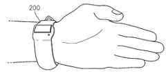
도 2a 및 도 2b는 도 1에 도시된 생체 신호 취득 장치의 외형을 보여주는 도면이다.2A and 2B are views illustrating an external appearance of the biosignal obtaining apparatus shown in FIG. 1.
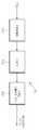
도 3은 도 1에 도시된 생체 신호 취득 장치의 구성을 보여주는 도면이다.FIG. 3 is a diagram illustrating a configuration of the biosignal obtaining apparatus illustrated in FIG. 1.
도 4는 도 1에 도시된 정서 인식 장치의 간략한 구성을 보여주는 도면이다.FIG. 4 is a diagram illustrating a brief configuration of the emotion recognition apparatus shown in FIG. 1.
도 5는 도 4에 도시된 정서 인식부의 상세 구성을 보여주는 블록도이다.FIG. 5 is a block diagram illustrating a detailed configuration of an emotion recognizer illustrated in FIG. 4.
도 6a 및 도 6b는 심박 신호의 분석에 사용될 ECG 신호 및 PPG 신호의 일례를 보여주는 도면이다.6A and 6B show examples of an ECG signal and a PPG signal to be used for analysis of a heartbeat signal.
도 7 및 도 8은 도 5에 도시된 심박 검출부의 상세 구성을 보여주는 도면이다.7 and 8 are views showing a detailed configuration of the heartbeat detection unit shown in FIG.
도 9는 도 7 및 도 8에 도시된 심박 검출부에 의해 구해진 심박 신호로부터 심박 변화율의 시계열을 구하는 과정을 보여주는 도면이다.FIG. 9 is a diagram illustrating a process of obtaining a time series of a heart rate change rate from a heartbeat signal obtained by the heartbeat detection unit illustrated in FIGS. 7 and 8.
도 10은 피부 전도 특성(SCR)의 검출에 사용되는 EDA 신호의 파형을 보여주 는 도면이다.10 shows waveforms of an EDA signal used for detection of skin conduction characteristics (SCR).
도 11은 도 5에 도시된 SCR 검출부의 구성을 보여주는 도면이다.FIG. 11 is a diagram illustrating a configuration of an SCR detector shown in FIG. 5.
도 12는 피부 온도의 변화를 검출하는데 사용되는 SKT 신호의 파형을 보여주는 도면이다.12 shows waveforms of SKT signals used to detect changes in skin temperature.
도 13은 도 5에 도시된 SKT Mean/Max 계산부의 구성을 보여주는 블록도이다.FIG. 13 is a block diagram illustrating a configuration of the SKT Mean / Max calculator shown in FIG. 5.
도 14는 도 5에 도시된 감산부 및 SVM 유닛의 구성을 보여주는 블록도이다.FIG. 14 is a block diagram illustrating a configuration of a subtractor and an SVM unit shown in FIG. 5.
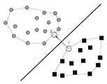
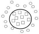
도 15a 및 도 15b는 도 14에 도시된 SVM 분류기의 정서 분류 결과를 보여주는 도면이다.15A and 15B are diagrams showing an emotion classification result of the SVM classifier shown in FIG. 14.
도 16은 본 발명의 바람직한 실시예에 의한 정서 인식 방법을 보여주는 흐름도이다.16 is a flowchart illustrating an emotion recognition method according to a preferred embodiment of the present invention.
도 17은 본 발명의 바람직한 실시예에 따른 정서 인식 수행 결과를 보여주는 도면이다.17 is a view showing a result of performing emotion recognition according to a preferred embodiment of the present invention.
< 도면의 주요 부분에 대한 부호의 설명 ><Description of Symbols for Main Parts of Drawings>
1 : 정서 인식 장치10 : 특징 분석부1: emotion recognition device 10: feature analysis unit
11 : 심박 분석부 12 : 심박 검출부11 heart
13 : 스펙트럼 분석부14 : Mean/Std 계산부13
15 : SCR 분석부16 : SCR 검출부15: SCR analyzer 16: SCR detector
17 : SCR 계산부18 : SKT Mean/Max 계산부17: SCR calculator 18: SKT Mean / Max calculator
20 : 감산부30 : SVM 유닛20: subtraction unit 30: SVM unit
100 : 정서 인식부200 : 생체 신호 취득 장치100: emotion recognition unit 200: biological signal acquisition device
본 발명은 정서 인식 장치 및 방법에 관한 것으로, 특히 사용자의 생리 신호를 모니터링 하여 사용자의 정서 상태를 인식하는 정서 인식 장치 및 방법에 관한 것이다.The present invention relates to an emotion recognition apparatus and a method, and more particularly, to an emotion recognition apparatus and method for monitoring a user's physiological signal to recognize the emotional state of the user.
정서(emotion)란 내적 자극 또는 외적 자극으로 정서의 변화와 생리적 활성도의 변화로 표출되는 정신적 상태를 의미한다. 이 정서 상태는 크게 긍정 정서(positive emotion)와 부정 정서(negative emotion)로 구분할 수 있다. 전자는 기쁨, 흐뭇(만족), 차분, 우쭐(의기양양, 기고만장) 등을 들 수 있고, 후자로는 슬픔, 못마땅(불만), 화남, 놀람, 두려움, 우울 등을 들 수 있다. 이 외에도 더 다양한 정서의 구분도 가능하다. 여기서, 내적 자극으로는 과거의 기억이나 주체적인 정서 자극 등을 들 수 있고, 외적 자극으로는 정서 주체의 자발적 자극 이외의 주위 환경에 의한 스트레스(stress)나 안티-스트레스(anti-stress)를 들 수 있다.Emotion refers to a mental state expressed as a change in emotion and a change in physiological activity as an internal stimulus or an external stimulus. This emotional state can be largely divided into positive emotion and negative emotion. The former may include joy, satisfaction, calmness, and usability (elation, desperation), and the latter may include sadness, displeasure, anger, surprise, fear, depression. In addition, more diverse emotions can be distinguished. Here, the internal stimulus may include past memories or subjective emotional stimuli, and the external stimulus may include stress or anti-stress caused by the surrounding environment other than the spontaneous stimulus of the emotional subject. Can be.
이와 같은 정서를 정의하기 위한 이론으로는, 생리학적 변화를 인식함으로써 정서를 경험하게 된다는 James-Lange 이론과, 정서에 대한 물리적 경험(psychological experience)과 물리적 반응(physiological reactions)이 동시에 일어난다는 Cannon-Bard 이론 등이 있다. James-Lange 이론은 정서의 근원이 말초 기관에 있다고 생각하는 반면, Cannon-Bard 이론은 그 근원을 뇌에 두고 있는 차이점이 있다.Theories for defining emotions include James-Lange's theory of experiencing emotions by recognizing physiological changes, and the Cannon- theory of simultaneous physical and physiological reactions to emotions. Bard's theory. The James-Lange theory considers the source of emotion to be in the peripheral organs, while the Cannon-Bard theory differs in keeping the source in the brain.
앞에서 설명한 바와 같이, 내부적/외부적 자극에 의해 정서상태에 일어난 변화는 자율신경계의 조절에 의해 발생되는 생리적인 특성들의 변화를 수반한다. 따라서, 정서상태의 변화는, 심장박동, 근전도, 피부 전기 전도도 변화, 체온 변화 등과 같이 생리적인 변화를 반영하는 신호들의 측정을 통해 인식될 수 있다. 이 같은 생리신호들은 적절한 생체신호센서를 통하여 측정될 수 있다.As described above, changes in the emotional state by internal / external stimuli involve changes in the physiological characteristics caused by the regulation of the autonomic nervous system. Therefore, the change in the emotional state can be recognized through the measurement of signals reflecting physiological changes such as heart rate, electromyography, skin electrical conductivity change, body temperature change, and the like. Such physiological signals can be measured through a suitable biosignal sensor.
생체신호센서를 통해 취득된 생리신호를 바탕으로 정서를 인식하는 방법에 대해서는 과거 몇 건의 특허에서 이미 발표된 바 있다. 예를 들면, 1997년 10월, Zawilinski에 의해 취득된 U. S. Pat. No. 5,676,138, "EMOTIONAL RESPONSE ANALYZER SYSTEM WITH MULTIMEDIA DISPLAY"에서는, TV 등의 자극 수단으로부터 발생된 자극에 의해 발생된 감정상태를 해석하는 장치를 개시하고 있다. 그러나, 이 방법은 제한적인 실험 데이터 및 그에 따른 실험 결과를 나타낼 뿐만 아니라, z-score를 사용하여 감정상태를 구분하므로 정확도가 낮은 문제점이 있다.How to recognize the emotion based on the physiological signal obtained through the bio-signal sensor has already been published in several patents. For example, U. S. Pat., Obtained in October 1997 by Zawilinski. No. 5,676, 138, "EMOTIONAL RESPONSE ANALYZER SYSTEM WITH MULTIMEDIA DISPLAY", discloses an apparatus for analyzing an emotional state generated by a stimulus generated from a stimulus means such as a TV. However, this method not only shows limited experimental data and experimental results, but also has a problem of low accuracy because it uses z-score to distinguish emotional states.
본 발명이 이루고자 하는 기술적 과제는, 손목 시계 형태와 같이 신체에 착용 가능한 센서로부터 비침습적인 생리 신호를 취득하고, 이를 근거로 하여 사용자의 정서 상태를 인식할 수 있는 정서 인식 장치 및 방법을 제공하는데 있다.The technical problem to be achieved by the present invention is to provide an emotion recognition apparatus and method that can acquire a non-invasive physiological signal from a sensor wearable on the body, such as a wrist watch, and can recognize the emotional state of the user based on this. have.
본 발명이 이루고자 하는 기술적 과제는, 사용자로부터 취득된 생리 신호를 짧은 시간 동안 모니터링 하여 사용자의 정서 상태를 정확하게 인식할 수 있는 정서 인식 장치 및 방법을 제공하는데 있다.An object of the present invention is to provide an emotion recognition apparatus and method capable of accurately recognizing an emotional state of a user by monitoring a physiological signal acquired from a user for a short time.
상기의 과제를 이루기 위하여 본 발명에 의한 정서 인식 시스템은, 사용자의 신체에 착용되어 적어도 하나 이상의 생체 신호를 취득하는 생체 신호 취득 장치; 및 상기 생체 신호들로부터 정서 인식에 사용될 복수 개의 특징 값들을 추출하고, 에스브이엠(Support Vector Machine : SVM) 분류기를 이용한 상기 특징 값들을 학습을 통해서 상기 사용자의 정서 상태를 인식하는 정서 인식 장치를 포함하는 것을 특징으로 한다.In order to achieve the above object, the emotion recognition system according to the present invention, the biological signal acquisition device which is worn on the body of the user to acquire at least one or more biological signals; And an emotion recognition apparatus for extracting a plurality of feature values to be used for emotion recognition from the bio signals and recognizing the emotional state of the user by learning the feature values using a support vector machine (SVM) classifier. It is characterized by including.
상기의 과제를 이루기 위하여 본 발명에 의한 정서 인식 장치는, 사용자로부터 취득된 심전도(ECG) 신호, 광혈류량(PPG) 신호, 피부전기활동(EDA) 신호, 및 피부 온도(SKT) 신호를 분석하여 상기 사용자의 정서를 인식하는데 필요한 복수 개의 특징 값들을 추출하는 특징 분석부; 상기 특징 분석부에서 추출된 상기 특징 값들과, 상기 사용자의 평상시 정서 상태에서 추출된 특징 값들과의 차이를 구하는 감산부; 및 상기 감산부에서 구해진 상기 차이 값을 분석하여 상기 사용자의 각 정서 별 강도를 표시하고, 표시된 상기 정서별 강도들 중 강도가 가장 크게 나타난 정서를 상기 사용자의 정서 상태로 인식하는 정서 분류 수단을 포함하는 것을 특징으로 한다.In order to achieve the above object, the emotion recognition apparatus according to the present invention analyzes an electrocardiogram (ECG) signal, an optical blood flow (PPG) signal, an electrodermal activity (EDA) signal, and a skin temperature (SKT) signal obtained from a user. A feature analyzer extracting a plurality of feature values required to recognize the emotion of the user; A subtraction unit for obtaining a difference between the feature values extracted by the feature analyzer and feature values extracted in the user's usual emotional state; And an emotion classification means for analyzing the difference value obtained by the subtraction unit to display the intensity for each emotion of the user and to recognize the emotion having the greatest intensity among the displayed intensity of emotions as the emotional state of the user. Characterized in that.
상기의 과제를 이루기 위하여 본 발명에 의한 정서 인식 방법은, (a) 사용자로부터 적어도 하나 이상의 생체 신호를 입력받는 단계; (b) 상기 생체 신호들을 분석하여 상기 사용자의 정서 인식에 사용될 복수 개의 특징 값들을 추출하는 단계; (c) 상기 (b) 단계에서 추출된 상기 복수개의 특징 값들과, 상기 사용자의 평상시 정서에서 추출된 특징 값들간의 차이를 구하는 단계; (d) 에스브이엠 분류기를 통해 상기 (c) 단계에서 계산된 상기 차이값을 분석하여 상기 사용자의 각 정서별 강도를 표시하는 단계; 및 (e) 상기 각 정서들 중 가장 큰 강도를 나타내는 정서를 상기 사용자의 정서 상태로 결정하는 단계를 포함하는 것을 특징으로 한다.In order to achieve the above object, the emotion recognition method according to the present invention, (a) receiving at least one or more bio-signals from the user; (b) extracting a plurality of feature values to be used for emotional recognition of the user by analyzing the bio signals; (c) obtaining a difference between the feature values extracted in step (b) and feature values extracted from the user's usual emotion; (d) analyzing the difference value calculated in the step (c) through an SMB classifier to display the intensity for each emotion of the user; And (e) determining an emotion indicating the greatest intensity among the emotions as the emotional state of the user.
이하에서, 첨부된 도면을 참조하여 본 발명의 바람직한 실시예에 대하여 상세히 설명한다.Hereinafter, with reference to the accompanying drawings will be described in detail a preferred embodiment of the present invention.
도 1은 본 발명의 바람직한 실시예에 따른 정서 인식 시스템의 전체 구성을 간략하게 보여주는 도면이고, 도 2a 및 도 2b는 도 1에 도시된 생체 신호 취득 장치의 외형을 보여주는 도면이다. 도 1을 참조하면, 본 발명에 따른 정서 인식 장치는 크게 생체 신호 취득 장치(200)와 정서 인식 장치(1)로 구성된다.1 is a view schematically showing the overall configuration of the emotion recognition system according to a preferred embodiment of the present invention, Figures 2a and 2b is a view showing the appearance of the biological signal acquisition device shown in FIG. Referring to FIG. 1, an emotion recognition apparatus according to the present invention is largely composed of a
생체 신호 취득 장치(200)는, 도 1 및 도 2에 도시된 바와 같이 사용자의 신체에 손목 시계 등의 형태로 착용되어, 그 내부에 구비된 센서(미 도시됨)를 통해 광혈류량(photoplethysmogram ; PPG), 심전도(electrocardiogram ; ECG), 피부전기활동(electrodermal Activity ; EDA), 피부 온도(skin temperature ; SKT) 등과 같은 생체 신호를 비침습적으로 측정한다. 생체 신호 취득 장치(200)를 통해 취득된 생체 신호는 정서 인식 장치(1)에게 무선으로 전송되어, 사용자의 정서 상태를 인식하는 데 사용된다. 정서 인식 장치(1)는 입력되는 생체 신호를 분석할 수 있는 알고리즘이 저장된 컴퓨터 또는 이에 상응하는 연산 장치로 구성된다. 상기 생체신호들의 취득을 위해 사용되는 센서에 대한 구체적인 내용은 Medical instrumentation (J. G. Webster, 1999) 등에 상세히 설명되어 있다.As shown in FIGS. 1 and 2, the biological
도 3 및 도 4는 도 1에 도시된 생체 신호 취득 장치(200) 및 정서 인식 장치(1)의 구성을 각각 보여주는 도면이다.3 and 4 are diagrams illustrating the structures of the
먼저, 도 3을 참조하면, 생체 신호 취득 장치(200)는 사용자의 생체 신호를 비침습적으로 받아들이는 적어도 하나 이상의 센서와, 상기 센서로부터 입력된 적 어도 하나 이상의 생체 신호들(physiological signals)을 증폭하고 필터링하는 증폭/필터링부(205), 증폭/필터링부(205)를 통해 증폭 및 필터링된 신호들을 각 신호별로 분류하여 출력하는 멀티플렉서(206), 상기 멀티플렉서(206)의 출력을 디지털 신호로 변환하는 A/D 컨버터(207), 및 A/D 컨버터(207)에 의해 변환된 디지털 신호들을 RF 신호로 변환한 후, 상기 신호를 안테나(209)를 통해 정서 인식 장치(1)로 무선 전송하는 RF 송신부(208)를 포함한다.First, referring to FIG. 3, the
도 4를 참조하면, 정서 인식 장치(1)는 생체 신호 취득 장치(200)로부터 전송되는 사용자의 생체 신호들을 안테나(101)를 통해 받아들이는 RF 수신부(102)와, RF 수신부(102)에 의해 수신된 생체 신호들을 분석하여 사용자의 정서 상태를 인식하는 정서 인식부(100)를 포함한다. 여기서, RF 수신부(102)와 정서 인식부(100)는 RS232C와 같은 통신 프로토콜을 사용하여 신호를 전송한다. 그러나, 이는 신호 전송 방법의 일례에 불과하며, 회로의 구성에 따라 다양한 통신 프로토콜이 사용될 수 있다.Referring to FIG. 4, the
도 5는 도 4에 도시된 정서 인식부(100)의 상세 구성을 보여주는 블록도이다. 도 5를 참조하면, 본 발명에 따른 정서 인식부(100)는 생체 신호 취득 장치(200)로부터 취득된 생체 신호들의 특징을 분석하는 특징 분석부(10), 특징 분석부(10)에서 분석된 결과와 사용자의 평상시 정서를 나타내는 특징 값들과의 차이를 구하는 감산부(20), 및 감산부(20)에서 구해진 특징 값들의 차이를 분석하여 정서를 분류하고 인식하는 SVM 유닛(Support Vector Machine Unit; 30)을 포함한다.5 is a block diagram illustrating a detailed configuration of the
특징 분석부(10)는 ECG 신호 또는 PPG 신호를 받아들여 심박을 검출하고 심 박과 관련된 특징 값들을 추출하는 심박 분석부(11), EDA 신호를 받아들여 피부 전도 특성(skin conductance response ; SCR)과 관련된 특징 값들을 추출하는 SCR 분석부(15), 및 SKT 신호를 받아들여 SKT와 관련된 특징 값들(즉, SKT의 평균 값(Mean) 및 최대 값(Max))을 추출하는 SKT Mean/Max 계산부(18)를 포함한다.The
심박 분석부(11)는 ECG 신호 또는 PPG 신호를 받아들여 심박을 검출하는 심박 검출부(12), 검출된 심박신호로부터 심박변화율(heart rate variability ; HRV)의 시계열을 추출하는 HRV 추출부, 추출된 HRV의 스펙트럼을 분석하는 스펙트럼 분석부(13), 및 검출된 심박 신호(Det)의 평균 값(Mean) 및 표준 편차 값(standard deviation ; Std)을 구하는 Mean/Std 계산부(14)를 포함한다. 그리고, SCR 분석부(15)는 EDA 신호를 받아들여 SCR을 검출하는 SCR 검출부(16), 및 SCR의 크기(amplitude) 등과 같은 파라미터들을 계산하는 SCR 계산부(17)를 포함한다.The
도 6a 및 도 6b는 심박 신호의 분석에 사용될 ECG 신호 및 PPG 신호의 일례를 보여주는 도면이고, 도 7 및 도 8은 도 5에 도시된 심박 검출부(12)의 상세 구성을 보여주는 도면이다. 여기서, 도 7에 도시된 심박 검출부(12)는 입력 신호가 ECG 신호인 경우의 회로 구성을 나타내고, 도 8에 도시된 심박 검출부(12')는 입력 신호가 PPG 신호인 경우의 회로 구성을 각각 나타낸다.6A and 6B are views showing an example of an ECG signal and a PPG signal to be used for the analysis of the heartbeat signal, and FIGS. 7 and 8 are views showing the detailed configuration of the
먼저 도 7을 참조하면, 본 발명에 의한 심박 검출부(12)는 밴드패스 필터(bandpass filter ; BPF)(121), 메디안 필터(median filter ; MF)(122), 가산부(123), 및 Teager 에너지 연산부(124)를 포함한다.First, referring to FIG. 7, the
밴드패스 필터(121)는 입력되는 신호 중에서 ECG 신호가 존재하는 대역만을 통과시키고, 메디안 필터(122)는 밴드패스 필터링 된 결과에 존재하는 저주파노이즈 성분을 추정해준다. 가산부(123)는 밴드패스 필터링 결과에 메디안 필터링 결과의 사이에 존재하는 차이를 계산하여 저주파 노이즈 성분을 제거한다. 저주파 노이즈 성분이 제거된 가산부(123)의 출력 신호는 Teager 에너지 연산부(124)로 입력되어 심박 신호의 추출에 사용된다. Teager 에너지 연산부(124)는 입력되는 신호에 Ψ(x(t))로 표시되는 Teager 에너지 오퍼레이터(Teager Energy Operator ; TEO)를 취해줌으로써 심박 신호를 검출한다. Teager 에너지 오퍼레이터는 입력신호의 순간진폭과 순간주파수의 곱에 비례하는 값을 발생하므로, 심전도의 QRS 피크의 검출에 매우 유용하다. 이에 대한 자세한 설명은 1998년, S. Mukhopadhyay와 G. C. Ray에 의해서 IEEE Trans. on Biomed. Eng., pp. 180-187에 발표된 논문, "A new interpretation of nonlinear energy operator and its efficacy in spike detection" 등에 개시되어 있다.The
앞에서 설명한 바와 같은 심박 검출부(12)에 의하면, 도 6a에 도시된 ECG 신호 상에 화살표로 표시된 부분이 심박 신호(Det)로서 추출된다.According to the
계속해서 도 8을 참조하면, 본 발명에 의한 심박 검출부(12')는 밴드패스 필터(121), 메디안 필터(122), 가산부(123), 정합 필터(Matched Filter ; 125), 및 제로 클리퍼(zero clipper ; 126)를 포함한다.8, the
밴드패스 필터(121)는 입력되는 신호 중에서 PPG 신호가 존재하는 대역만을 통과시키고, 메디안 필터(122)는 밴드패스 필터링 된 결과에 존재하는 저주파노이즈 성분을 추정해준다. 가산부(123)는 밴드패스 필터링 결과에 메디안 필터링 결과의 사이에 존재하는 차이를 계산하여 저주파 노이즈 성분을 제거한다. 저주파 노이즈 성분이 제거된 가산부(123)의 출력 신호는 정합 필터(125)로 입력되어, PPG 신호가 가지고 있는 특정 신호(즉, 심박 신호)를 추출하는 데 사용된다. 정합 필터(125)를 통해 추출된 특정 신호는 제로 클리퍼(125)를 통해 제로 클리핑 과정을 거친 후 심박 신호(Det)로서 출력된다. 여기서, 정합 필터(125)의 파라미터는 필요시 업데이트 될 수 있다. 이와 같은 구성을 가지는 심박 검출부(12')에 의하면, 도 6b에 도시된 PPG 신호 상에 화살표로 표시된 부분이 심박 신호(Det)로서 추출된다.The
도 9는 도 7 및 도 8에 도시된 심박 검출부(12, 12')에 의해 구해진 심박 신호(Det)로부터 심박 변화율(heart rate variability ; HRV)의 시계열(time series)을 구하는 과정을 보여주는 도면이다.FIG. 9 is a diagram illustrating a process of obtaining a time series of heart rate variability (HRV) from a heartbeat signal Det obtained by the
도 9를 참조하면, ECG 또는 PPG 신호(1200)가 취득된 경우, 이를 확대해 보면 1210과 같은 형태의 파형이 나타나게 된다. ECG 또는 PPG 신호는 참조번호 1200 또는 1210과 같이 주기적인 펄스를 나타내는데, 이 펄스는 최대 값 부분인 R과, R을 중심으로 좌우에 위치한 최소 값 부분인 Q, S로 구성된 QRS 파형을 나타낸다.Referring to FIG. 9, when the ECG or
도 9에서 1210으로 표시된 파형에서 화살표로 표시된 부분이 심박 신호의 최대 값 부분인 R 파형이 되며, 이 부분이 도 7 및 도 8에 도시된 심박 검출부(12, 12')에 의해 추출되어 ECG 또는 PPG 신호의 순간 R-R 파형(1230)을 나타내게 된다. 이 순간 R-R 파형(1230)에 이동 평균 보간법(moving average interpolation)을 적용하게 되면 1250으로 표시된 바와 같은 심박 변화율(HRV)의 시계열(time series) 이 추출된다. 이와 같은 심박 변화율의 시계열(1250)을 구하는 방법은 1986년 R. D. Berger 등에 의해 IEEE Trans. Biomed. Eng., vol. 33에 실린 논문, "An efficient algorithm for spectral analysis of heart rate variability" 등에 개시되어 있다. 이 같은 심박 변화율(HRV) 신호는 교감신경계/부교감 신경계의 활성정도를 정량적으로 파악할 수 있는 지표가 된다.In the waveform indicated by 1210 in FIG. 9, the portion indicated by the arrow becomes the R waveform, which is the maximum value portion of the heartbeat signal, which is extracted by the
다시 도 5를 참조하면, 도 7 또는 도 8에 의해 구해진 심박 신호(Det)는 도 9에 도시된 방법에 의해 심박 변화율(HRV)의 시계열로 변환된 후 스펙트럼 분석부(13) 및 Mean/Std 계산부(14)로 입력된다.Referring back to FIG. 5, the heart rate signal Det obtained by FIG. 7 or 8 is converted into a time series of HRV by the method shown in FIG. 9, and then the
스펙트럼 분석부(13)에서는 주어진 시계열에 대하여 다양한 차수의 AR(autoregressive), MA(moving average), ARMA(autoregressive moving average) 모델들을 추정한 후, 추정 오차를 나타내는 지표가 최소가 되는 특정 차수의 특정 모델을 선택하여 최적의 시계열 모델을 선정하고, 선정된 최적 모델로부터 스펙트럼을 구하는 방법을 사용하여 심박 변화율(HRV)의 스펙트럼을 분석한다. 여기서는 이 방법을 ARMAsel 알고리즘이라고 부른다. 이를 위해 사용되는 추정오차의 지표와 각 시계열 모델의 추정 방법은, P. M. T. Broersen에 의해 2000년, IEEE Transactions on instrumentation and measurement, vol. 49, no. 4, pp. 766-772에 발표된 논문, "Fact and fictions in spectral analysis"에 상세히 설명되어 있다.The
이와 같은 심박 변화율(HRV)의 주파수 영역 파라미터들은 이미 이전의 많은 연구에서 중요하게 취급되어 왔으며, 생리심리학적 연구에 있어서도 중요한 지표로 취급되어 오고 있다.These frequency-domain parameters of heart rate variability (HRV) have already been important in many previous studies and have been treated as important indicators in physiological and psychological studies.
본 발명에 의한 스펙트럼 분석부(13)에서는 심박변화율의 스펙트럼 해석에 있어서, 수 분에서 24 시간에 이르는 긴 신호를 대상으로 하는 기존의 피리어드그램(periodogram) 방법 대신, ARMAsel 알고리즘을 사용하여 50초 정도의 짧은 시간 동안의 신호 관측을 통해 심박 변화율(HRV)의 스펙트럼을 분석한다. 스펙트럼 분석부(13)에 의해 분석된 결과는 감산부(20)에게 사용자 정서 인식을 수행하기 위한 특징 값으로서 전달된다.In the
한편, 심박 검출부(12, 12')로부터 심박 변화율(HRV)의 시계열 신호를 받아들인 Mean/Std 계산부(14)는, 주어진 시계열에 대한 평균 및 표준 편차(Std)를 계산하여 이를 감산부(20)에게 사용자 정서 인식을 수행하기 위한 특징 값으로서 전달된다.Meanwhile, the Mean /
이어서, 도 5에 도시된 심박 분석부(11)에 구비된 SCR 분석부(15)의 상세 구성 및 동작을 살펴보면 다음과 같다.Next, a detailed configuration and operation of the
도 10은 피부 전도 특성(SCR)의 검출에 사용되는 EDA 신호의 파형을 보여주는 도면이다. 도 10에는 사용자로부터 발생된 EDA 신호의 파형(1600)과, EDA 신호의 파형(1600) 중 SCR의 특성이 추출되는 부분에 대한 확대 파형(1610)이 도시되어 있다. 1600 및 1610으로 표시된 신호는 SCR 분석부(15)에 구비된 SCR 검출부(16)로 입력된다.10 shows waveforms of an EDA signal used for detection of skin conduction characteristics (SCR). FIG. 10 illustrates a
도 11은 도 5에 도시된 SCR 검출부(16)의 구성을 보여주는 도면이다.FIG. 11 is a diagram illustrating a configuration of the
도 11을 참조하면, EDA 신호를 받아들여 피부 전도 특성을 검출하는 SCR 검 출부(16)는, 다운샘플러(down-sampler ; 161), 미분기(differentiator ; 162), 및 스무딩 컨볼루션 유닛(smoothing convolution unit ; 163)으로 구성된다.Referring to FIG. 11, an
다운샘플러(161)는 입력된 EDA 신호를 10 내지 12 개의 데이터로 다운 샘플링한다. 미분기(162)는 다운 샘플링된 결과를 미분하고, 스무딩 컨볼루션 유닛(163)은 길이가 20인 Bartlett 윈도우를 사용하여 미분 결과에 대한 스무딩 컨볼루션을 수행한다. 이와 같은 SCR 검출부(16)에 의하면, 입력된 EDA 신호는 이산 SCR 데이터(discrete SCR data) 형태로 출력된다.The
SCR 검출부(16)에 의해 취득된 이산 SCR 데이터는 SCR 분석부(15)에 구비된 SCR 계산부(17)로 입력되어, 일정시간 동안의 SCR 발생빈도(number of SCR/time), SCR의 크기(SCR amplitude), 및 SCR 상승 시간(SCR rise time) 등의 특징 값들을 발생한다. SCR 계산부(17)에 의해 구해진 SCR 특징 데이터들(즉, SCR 발생빈도, SCR의 크기, SCR 상승 시간 등)은 도 5에 도시된 바와 같이 감산부(20)로 각각 입력된다.Discrete SCR data acquired by the
계속해서, 도 5에 도시된 심박 분석부(11)의 SKT Mean/Max 계산부(18)에 대한 상세 구성 및 동작을 살펴보면 다음과 같다.Subsequently, a detailed configuration and operation of the SKT Mean /
도 12는 피부 온도의 변화를 검출하는데 사용되는 SKT 신호의 파형을 보여주는 도면이고, 도 13은 도 5에 도시된 SKT Mean/Max 계산부(18)의 구성을 보여주는 블록도이다.12 is a view showing a waveform of the SKT signal used to detect a change in skin temperature, Figure 13 is a block diagram showing the configuration of the SKT Mean /
도 13을 참조하면, SKT Mean/Max 계산부(18)는 다운 샘플러(181)와 Mean/Max 계산기(182)로 구성된다. SKT Mean/Max 계산부(18)는 도 12에 도시된 바와 같은 SKT 신호를 받아들여 상기 신호를 100 개 정도의 데이터로 다운 샘플링하고, 다운 샘플링된 데이터의 평균 값(Mean_SKT) 및 최대 값(Max_SKT)을 SKT의 특징 데이터로서 발생한다.Referring to FIG. 13, the SKT Mean /
앞에서 설명한 바와 같이, 특징 분석부(10)에 구비된 심박 분석부(11), SCR 분석부(15) 및 SKT Mean/Max 계산부(18)가 사용자로부터 입력된 복수 개의 생체 신호들로부터 사용자의 정서 인식에 필요한 특징 값들을 추출하고 나면, 상기 특징 값들은 감산부(20) 및 SVM 유닛(30)에 순차적으로 입력되어 사용자의 정서를 인식하게된다.As described above, the
도 14는 도 5에 도시된 감산부(20) 및 SVM 유닛(30)의 구성을 보여주는 블록도이다.FIG. 14 is a block diagram showing the configuration of the
도 14를 참조하면, 감산부(20)에는 사용자의 정서 인식에 기준이 되는 특징 값들로서 사용자의 평상시 정서 상태에 대한 특징 값들(Feature 1' - Feature 4')(즉, 사용자의 평상시 정서에서 취득된 생체 신호로부터 추출된 특징 값들)이 저장되어 있다. 감산부(20)는 특징 분석부(10)에 구비된 심박 분석부(11), SCR 분석부(15), 및 SKT Mean/Max 계산부(18)로부터 입력되는 복수개의 특징 값들(Feature 1 - Feature 4)과 사용자의 평상시 정서 상태에 대한 특징 값들(Feature 1' - Feature 4')과의 차이를 구하여 이를 SVM 유닛(30)으로 전송한다.Referring to FIG. 14, the
SVM 유닛(30)은, 감산부(20)에서 출력된 특징 값들의 차이에 응답해서 사용자의 정서 상태를 학습(training) 및 분류(classify)하는 SVM 분류기(Support Vector Machine Classifier ; 32)와, SVM 분류기(32)에 의해 학습된 결과를 저장하 는 데이터베이스(34), 및 SVM 분류기(32)에서 분류된 복수 개의 정서 상태 값들을 비교하여 최종 정서 상태를 선택하여 출력하는 비교기(36)를 포함한다.The
추출된 특징벡터들로부터 소정의 정서상태를 결정하는 것은 일종의 패턴인식 문제에 해당되며, 패턴인식을 위해서는 다양한 종류의 분류기가 적용될 수 있다. 일반적으로, 특정 정서상태를 나타내는 특징 벡터가 다차원 공간상에 하나의 확률분포를 형성하고 있고, 각 상태에 해당되는 확률 밀도 함수가 알려져 있기만 하면, Bayes' 법칙에 의해서 통계적으로 최적의 분류기가 구현될 수 있다.Determining a predetermined emotional state from the extracted feature vectors corresponds to a kind of pattern recognition problem, and various types of classifiers may be applied for pattern recognition. In general, as long as the feature vector representing a certain emotional state forms a probability distribution in multidimensional space, and the probability density function corresponding to each state is known, Bayes' law can provide a statistically optimal classifier. Can be.
그러나, 실제에 있어서 확률 밀도 함수를 정확히 아는 것은 불가능하기 때문에, Bayes' 법칙에 상응하는 규칙을 함축적으로 구현하는 파젠 윈도우 분류기(Parzen window classifier), 다중 퍼셉트론(multilayer perceptron) 등이 주로 사용되고 있다. 하지만, 이와 같은 종래의 분류기들은 일반화(generalization) 특성이 좋지 못하기 때문에, 학습에 사용되지 않은 새로운 데이터에 대해서는 오동작율이 상당히 높은 문제점을 가지고 있다. 뿐만 아니라, 상기 패턴 분류기는 특징벡터들의 분포가 상당히 넓고, 서로 다른 상태에 해당되는 분포들 간에 겹치는 부분들이 많기 때문에, 오동작율이 높아질 가능성이 매우 크다. 따라서, 본 발명에서는 상기와 같은 문제점을 해결하기 위해서, 높은 일반화 특성을 가지는 SVM 분류기(32)를 정서 인식을 위한 패턴 분류기로서 사용한다.However, since it is impossible to know exactly the probability density function in practice, the Parzen window classifier, the multilayer perceptron, etc., which implicitly implement the rules corresponding to Bayes' law, are mainly used. However, these conventional classifiers have a problem that the malfunction rate is considerably high for new data not used for learning because of poor generalization characteristics. In addition, since the pattern classifier has a considerably wide distribution of feature vectors and many overlapping portions corresponding to different states, there is a high possibility of malfunction. Therefore, in the present invention, in order to solve the above problems, the
SVM 분류기(32)는 고차원으로의 비선형적인 매핑(mapping)에 의해서 선형적 분리 가능성을 높일 수 있다. SVM 분류기(32)는, Vapnik의 통계적 학습 이론(statistical learning theory)을 근거로 하여 최적의 일반화 성능(generalization performance)을 갖는 선형분리기를 구현하는 방법을 기반으로 하여 구성된다. 이와 같은 특성을 갖는 SVM 분류기에 대한 보다 상세한 설명은, 1999년, V. Vapnik에 의해 IEEE Transactions on neural network, Vol. 10, No. 5, pp. 988-999에 발표된 논문, "An overview of statistical learning theory" 등에 개시되어 있다.The
도 15a 및 도 15b는 도 14에 도시된 SVM 분류기(32)의 정서 분류 결과를 보여주는 도면이다. 본 발명에 의한 SVM 분류기(32)는, 입력 공간의 비선형적인 높은 차수를 특징 공간(feature space)에서 선형적으로 투영하여 해석함으로써, 도 15a 및 도 15b에 도시된 바와 같이 각 특징 데이터(즉, 사용자의 정서) 사이에 최적의 경계(즉, 최적분리면)를 제시한다.15A and 15B are diagrams showing an emotion classification result of the
다시 도 14를 참조하면, SVM 분류기(32)에 의해 수행된 정서 분류의 결과는 각 정서별로 분류된 후, 각 정서별 강도가 숫자로 표시되어 출력된다. 예를 들어, 스트레스(Stress)에 해당되는 정서는 0.3(또는 30%), 슬픔(Sad)에 해당되는 정서는 0.6(또는 60%), 그리고, 분노(Anger)에 해당되는 정서는 0.1(또는 10%) 등과 같이 각 정서별 강도가 숫자로 표시된다.Referring back to FIG. 14, the result of emotion classification performed by the
비교기(36)는 SVM 분류기(32)로부터 출력되는 복수 개의 정서에 대한 강도를 받아들여, 이들 중 가장 큰 강도를 나타내는 정서를 최종 정서 인식 결과(Emotion)로서 출력한다. 이 때, 데이터베이스(34)에는 어떤 특징 값들이 입력되는 경우에는 어떤 정서로 인식되는가에 대한 정보들이 저장된다. 이 같은 데이터베이스(34)에 대한 데이터의 갱신은 SVM 분류기(32)의 학습 시 수행되고, 일단 SVM 분류기(32)의 학습이 끝나게 되면 데이터베이스(34)에 대한 데이터의 갱신은 수행되지 않는다. 따라서, 데이터베이스(34)는 개발자 입장에서 필요한 부분이고, 사용자를 위해 개발이 완료된 정서 인식 시스템에는 데이터베이스(34)가 제공되지 않아도 된다.The
도 16은 본 발명의 바람직한 실시예에 의한 정서 인식 방법을 보여주는 흐름도이다. 도 16을 참조하면, 본 발명에 의한 정서 인식 방법은, 먼저 ECG/PPG, EDA, SKT와 같은 복수 개의 생체 신호를 입력받는다(1010 단계). 상기 생체 신호는 인체에 착용 가능한 센서가 구비된 생체 신호 취득 장치(200)에 의해 취득된 후, 정서 인식 장치(1)로 무선 전송된다.16 is a flowchart illustrating an emotion recognition method according to a preferred embodiment of the present invention. Referring to FIG. 16, the emotion recognition method according to the present invention first receives a plurality of bio signals such as ECG / PPG, EDA, and SKT (step 1010). The biosignal is acquired by the
컴퓨터와 같이 정서 인식 프로그램이 저장된 소정의 프로세서로 구성된 정서 인식 장치(1)는 1010 단계에서 입력된 복수개의 생체 신호를 분석하여 사용자의 정서 인식에 사용되는 복수 개의 특징 값들을 추출한다(1020 단계). 1020 단계에서 추출되는 특징 값으로는 ECG/PPG 신호로부터 추출된 심박 신호의 스펙트럼, 심박 신호의 평균 값/표준편차 값, EDA 신호로부터 검출된 SCR 관련 파라미터들, 및 SKT 신호로부터 추출된 SKT 신호의 평균 값/최대 값 등이 있다.The
1020 단계에서 추출된 복수개의 특징 값들은 감산부(20)로 입력되어, 추출된 복수개의 특징 값들과 정서 인식의 기준이 되는 특징 값들간의 차이가 구해진다(1030 단계). 여기서, 정서 인식의 기준이 되는 특징 값들은 사용자가 특정 정서에 치우치지 않은 평상시의 정서를 나타내는 특징 값으로서, 상기 기준이 되는 특징 값들은 감산부(20)에 미리 저장되어 있다.The plurality of feature values extracted in
특징 값들의 차이가 구해지면, 상기 차이 값들은 SVM 유닛(30)으로 입력되어 사용자 정서 인식이 수행된다(1040 단계). SVM 유닛(30)은 사용자의 정서 상태를 각 정서 별로 구분하고, 구분된 각각의 정서들 중 가장 큰 강도를 나타내는 정서를 선택하여 이를 최종 정서 인식 결과로서 출력한다(1050 단계).When the difference between the feature values is obtained, the difference values are input to the
도 17은 본 발명의 바람직한 실시예에 따른 정서 인식 수행 결과를 보여주는 도면이다. 도 17을 참조하면, 본 발명에 따른 정서 인식 시스템은 참조 번호 41 내지 43으로 표시된 사용자의 생체 신호를 받아들여 정서를 분류한 결과를 참조 번호 44와 같이 나타낸다. 그리고, 정서 분류 결과 중 가장 많은 정서의 부분을 차지하는 정서(예를 들면, Sad)를 참조번호 45와 같이 정서 인식의 최종 결과로서 출력하게 된다.17 is a view showing a result of performing emotion recognition according to a preferred embodiment of the present invention. Referring to FIG. 17, the emotion recognition system according to the present invention receives a biosignal of a user indicated by
이 같은 본 발명에 의한 정서 인식 장치 및 방법은, 기존의 방법들에 비해 다음과 같은 장점을 갖는다. 예를 들어, 기존의 정서 인식 방법들이 뇌파나 안면근전도 등을 이용하여 일상적으로 사용이 불가능한 반면, 본 발명은 손목 시계 형태로 착용되는 센서를 통해 비침습적으로 취득되는 생체 신호를 이용하기 때문에 실용화가 매우 용이한 장점을 가진다. 뿐만 아니라, 본 발명에 의한 정서 인식 장치 및 방법은 약 50초 정도의 짧은 시간의 생체 신호의 관측으로도 기존의 방법에 비해 현저히 높은 정서 인식 결과를 갖는다.The emotion recognition apparatus and method according to the present invention has the following advantages as compared to the existing methods. For example, while conventional emotion recognition methods cannot be routinely used by using EEG or facial EMG, the present invention uses practically non-invasive bio signals obtained through a sensor worn in the form of a wrist watch. It has a very easy advantage. In addition, the apparatus and method for emotion recognition according to the present invention has a significantly higher emotion recognition result than the conventional method even with observation of a biosignal of a short time of about 50 seconds.
본 발명은 또한 컴퓨터로 읽을 수 있는 기록매체에 컴퓨터가 읽을 수 있는 코드로서 구현하는 것이 가능하다. 컴퓨터가 읽을 수 있는 기록매체는 컴퓨터 시스템에 의하여 읽혀질 수 있는 데이터가 저장되는 모든 종류의 기록장치를 포함한다. 컴퓨터가 읽을 수 있는 기록매체의 예로는 ROM, RAM, CD-ROM, 자기 테이프, 플로피 디스크, 광데이터 저장장치 등이 있으며, 또한 캐리어 웨이브(예를 들어 인터넷을 통한 전송)의 형태로 구현되는 것도 포함한다. 또한 컴퓨터가 읽을 수 있는 기록매체는 네트워크로 연결된 컴퓨터 시스템에 분산되어, 분산방식으로 컴퓨터가 읽을 수 있는 코드로 저장되고 실행될 수 있다.The invention can also be embodied as computer readable code on a computer readable recording medium. The computer-readable recording medium includes all kinds of recording devices in which data that can be read by a computer system is stored. Examples of computer-readable recording media include ROM, RAM, CD-ROM, magnetic tape, floppy disk, optical data storage, and the like, and may also be implemented in the form of a carrier wave (for example, transmission over the Internet). Include. The computer readable recording medium can also be distributed over network coupled computer systems so that the computer readable code is stored and executed in a distributed fashion.
이상에 설명한 바와 같이, 본 발명에 의한 정서 인식 장치 및 방법에 의하면, 신체에 불편함 없이 상시 착용이 가능한 센서로부터 생리 신호를 취득하고, 취득된 신호를 짧은 시간 동안 모니터링 하여 사용자의 정서 상태를 정확하게 인식할 수 있다.As described above, according to the emotion recognition apparatus and method according to the present invention, the physiological signal is acquired from a sensor that can be worn at all times without any inconvenience to the body, and the acquired signal is monitored for a short time to accurately monitor the user's emotional state. I can recognize it.
Claims (17)
Translated fromKoreanPriority Applications (3)
| Application Number | Priority Date | Filing Date | Title |
|---|---|---|---|
| KR1020020003868AKR100580618B1 (en) | 2002-01-23 | 2002-01-23 | Apparatus and method for recognizing user emotion through short time monitoring of physiological signals |
| JP2003014133AJP4101069B2 (en) | 2002-01-23 | 2003-01-23 | User emotion recognition device and method through short-term monitoring of physiological signal |
| US10/348,976US7547279B2 (en) | 2002-01-23 | 2003-01-23 | System and method for recognizing user's emotional state using short-time monitoring of physiological signals |
Applications Claiming Priority (1)
| Application Number | Priority Date | Filing Date | Title |
|---|---|---|---|
| KR1020020003868AKR100580618B1 (en) | 2002-01-23 | 2002-01-23 | Apparatus and method for recognizing user emotion through short time monitoring of physiological signals |
Publications (2)
| Publication Number | Publication Date |
|---|---|
| KR20030063640A KR20030063640A (en) | 2003-07-31 |
| KR100580618B1true KR100580618B1 (en) | 2006-05-16 |
Family
ID=19718772
Family Applications (1)
| Application Number | Title | Priority Date | Filing Date |
|---|---|---|---|
| KR1020020003868AExpired - Fee RelatedKR100580618B1 (en) | 2002-01-23 | 2002-01-23 | Apparatus and method for recognizing user emotion through short time monitoring of physiological signals |
Country Status (3)
| Country | Link |
|---|---|
| US (1) | US7547279B2 (en) |
| JP (1) | JP4101069B2 (en) |
| KR (1) | KR100580618B1 (en) |
Cited By (2)
| Publication number | Priority date | Publication date | Assignee | Title |
|---|---|---|---|---|
| KR100972208B1 (en)* | 2007-08-21 | 2010-07-23 | 주식회사 에스씨티 | Bio signal measuring instrument |
| KR101002365B1 (en) | 2009-05-19 | 2010-12-17 | 동서대학교산학협력단 | Pulse wave propagation time measurement system and method |
Families Citing this family (129)
| Publication number | Priority date | Publication date | Assignee | Title |
|---|---|---|---|---|
| KR20040032451A (en) | 2002-10-09 | 2004-04-17 | 삼성전자주식회사 | Mobile device having health care function and method of health care using the same |
| CN100558290C (en)* | 2003-08-08 | 2009-11-11 | 量子技术公司 | electrophysiological intuitive indicator |
| US20050054381A1 (en)* | 2003-09-05 | 2005-03-10 | Samsung Electronics Co., Ltd. | Proactive user interface |
| KR100662335B1 (en)* | 2004-06-18 | 2007-01-02 | 엘지전자 주식회사 | Method of conveying and expressing emotion of mobile terminal user, and communication system for him |
| JP4590555B2 (en)* | 2004-09-02 | 2010-12-01 | 国立大学法人長岡技術科学大学 | Sensitive state discrimination method and apparatus |
| EP1871219A4 (en)* | 2005-02-22 | 2011-06-01 | Health Smart Ltd | Methods and systems for physiological and psycho-physiological monitoring and uses thereof |
| US20070150281A1 (en)* | 2005-12-22 | 2007-06-28 | Hoff Todd M | Method and system for utilizing emotion to search content |
| KR100763236B1 (en)* | 2006-05-09 | 2007-10-04 | 삼성전자주식회사 | Video editing device and method using bio signals |
| WO2008008905A2 (en) | 2006-07-12 | 2008-01-17 | Arbitron Inc. | Methods and systems for compliance confirmation and incentives |
| US20080096533A1 (en)* | 2006-10-24 | 2008-04-24 | Kallideas Spa | Virtual Assistant With Real-Time Emotions |
| US9833184B2 (en)* | 2006-10-27 | 2017-12-05 | Adidas Ag | Identification of emotional states using physiological responses |
| US8679008B2 (en)* | 2007-02-16 | 2014-03-25 | Galvanic Limited | Biosensor device and method |
| DE102007036277A1 (en)* | 2007-07-31 | 2009-02-05 | Technische Universität Berlin | Method and device for automatic pattern recognition |
| US9513699B2 (en)* | 2007-10-24 | 2016-12-06 | Invention Science Fund I, LL | Method of selecting a second content based on a user's reaction to a first content |
| US20090112694A1 (en)* | 2007-10-24 | 2009-04-30 | Searete Llc, A Limited Liability Corporation Of The State Of Delaware | Targeted-advertising based on a sensed physiological response by a person to a general advertisement |
| US20090112696A1 (en)* | 2007-10-24 | 2009-04-30 | Jung Edward K Y | Method of space-available advertising in a mobile device |
| US20090113297A1 (en)* | 2007-10-24 | 2009-04-30 | Searete Llc, A Limited Liability Corporation Of The State Of Delaware | Requesting a second content based on a user's reaction to a first content |
| US20090112693A1 (en)* | 2007-10-24 | 2009-04-30 | Jung Edward K Y | Providing personalized advertising |
| US9582805B2 (en)* | 2007-10-24 | 2017-02-28 | Invention Science Fund I, Llc | Returning a personalized advertisement |
| US9192300B2 (en)* | 2008-05-23 | 2015-11-24 | Invention Science Fund I, Llc | Acquisition and particular association of data indicative of an inferred mental state of an authoring user |
| US8615664B2 (en)* | 2008-05-23 | 2013-12-24 | The Invention Science Fund I, Llc | Acquisition and particular association of inference data indicative of an inferred mental state of an authoring user and source identity data |
| US9161715B2 (en)* | 2008-05-23 | 2015-10-20 | Invention Science Fund I, Llc | Determination of extent of congruity between observation of authoring user and observation of receiving user |
| US20090292658A1 (en)* | 2008-05-23 | 2009-11-26 | Searete Llc, A Limited Liability Corporation Of The State Of Delaware | Acquisition and particular association of inference data indicative of inferred mental states of authoring users |
| US9101263B2 (en)* | 2008-05-23 | 2015-08-11 | The Invention Science Fund I, Llc | Acquisition and association of data indicative of an inferred mental state of an authoring user |
| EP2335232B1 (en)* | 2008-09-10 | 2012-08-15 | Koninklijke Philips Electronics N.V. | Bed exit warning system |
| CN108279781B (en)* | 2008-10-20 | 2022-01-14 | 皇家飞利浦电子股份有限公司 | Controlling influence on a user in a reproduction environment |
| JP2011022869A (en)* | 2009-06-17 | 2011-02-03 | Iwao Kobayashi | Communication support device for severely disabled people |
| KR101262922B1 (en)* | 2009-12-10 | 2013-05-09 | 한국전자통신연구원 | Apparatus and method for determining emotional quotient according to emotion variation |
| PT2515760E (en)* | 2009-12-21 | 2014-05-23 | Fundación Tecnalia Res & Innovation | Affective well-being supervision system and method |
| US9138186B2 (en)* | 2010-02-18 | 2015-09-22 | Bank Of America Corporation | Systems for inducing change in a performance characteristic |
| US8715179B2 (en)* | 2010-02-18 | 2014-05-06 | Bank Of America Corporation | Call center quality management tool |
| US8715178B2 (en)* | 2010-02-18 | 2014-05-06 | Bank Of America Corporation | Wearable badge with sensor |
| EP2542147A4 (en)* | 2010-03-04 | 2014-01-22 | Neumitra LLC | Devices and methods for treating psychological disorders |
| WO2011153318A2 (en)* | 2010-06-02 | 2011-12-08 | Q-Tec Systems Llc | Method and apparatus for monitoring emotion in an interactive network |
| KR20110135676A (en)* | 2010-06-11 | 2011-12-19 | 전자부품연구원 | Short-range communication processing system with improved communication compatibility for multi-bio signal processing |
| US10997526B2 (en)* | 2010-07-02 | 2021-05-04 | United States Of America As Represented By The Administrator Of Nasa | System and method for human operator and machine integration |
| US10192173B2 (en)* | 2010-07-02 | 2019-01-29 | The United States Of America As Represented By The Administrator Of The National Aeronautics And Space Administration | System and method for training of state-classifiers |
| WO2012063123A2 (en) | 2010-11-09 | 2012-05-18 | WOOW Inc. Limited | Apparatus and method for physical interaction over a distance using a telecommunication device |
| US9307190B2 (en) | 2010-11-09 | 2016-04-05 | Kanfield Capital Sa | Apparatus and method for physical interaction over a distance using a telecommunication device |
| TWI536195B (en)* | 2011-03-02 | 2016-06-01 | 緯創資通股份有限公司 | Devices and methods for receiving a physiological signal |
| DK2696754T3 (en) | 2011-04-14 | 2014-12-15 | Koninkl Philips Nv | Stress-measuring device and method |
| US20130198694A1 (en)* | 2011-06-10 | 2013-08-01 | Aliphcom | Determinative processes for wearable devices |
| US9069380B2 (en) | 2011-06-10 | 2015-06-30 | Aliphcom | Media device, application, and content management using sensory input |
| US20130174018A1 (en)* | 2011-09-13 | 2013-07-04 | Cellpy Com. Ltd. | Pyramid representation over a network |
| JP5772448B2 (en)* | 2011-09-27 | 2015-09-02 | 富士ゼロックス株式会社 | Speech analysis system and speech analysis apparatus |
| RU2634680C2 (en)* | 2011-11-22 | 2017-11-02 | Конинклейке Филипс Н.В. | Evaluation of cortisol level and psychological equilibrium or violation of psychological equilibrium |
| US9311825B2 (en) | 2011-12-22 | 2016-04-12 | Senstream, Inc. | Biometric sensing and processing apparatus for mobile gaming, education, and wellness applications |
| US9332363B2 (en) | 2011-12-30 | 2016-05-03 | The Nielsen Company (Us), Llc | System and method for determining meter presence utilizing ambient fingerprints |
| US20130204535A1 (en)* | 2012-02-03 | 2013-08-08 | Microsoft Corporation | Visualizing predicted affective states over time |
| PL398136A1 (en) | 2012-02-17 | 2013-08-19 | Binartech Spólka Jawna Aksamit | Method for detecting the portable device context and a mobile device with the context detection module |
| EP2816950A4 (en)* | 2012-02-22 | 2015-10-28 | Aclaris Medical Llc | Physiological signal detecting device and system |
| US20140324749A1 (en)* | 2012-03-21 | 2014-10-30 | Alexander Peters | Emotional intelligence engine for systems |
| US11006874B2 (en)* | 2012-08-13 | 2021-05-18 | Tata Consultancy Services Limited | Real-time stress determination of an individual |
| US9314159B2 (en) | 2012-09-24 | 2016-04-19 | Physio-Control, Inc. | Patient monitoring device with remote alert |
| US9418390B2 (en) | 2012-09-24 | 2016-08-16 | Intel Corporation | Determining and communicating user's emotional state related to user's physiological and non-physiological data |
| US10610159B2 (en) | 2012-10-07 | 2020-04-07 | Rhythm Diagnostic Systems, Inc. | Health monitoring systems and methods |
| US10244949B2 (en) | 2012-10-07 | 2019-04-02 | Rhythm Diagnostic Systems, Inc. | Health monitoring systems and methods |
| US10413251B2 (en) | 2012-10-07 | 2019-09-17 | Rhythm Diagnostic Systems, Inc. | Wearable cardiac monitor |
| WO2014097052A1 (en)* | 2012-12-20 | 2014-06-26 | Koninklijke Philips N.V. | Monitoring a waiting area |
| TWI494079B (en)* | 2012-12-21 | 2015-08-01 | Univ Nat Cheng Kung | Stress condition detecting apparatus |
| US10022053B2 (en)* | 2013-02-22 | 2018-07-17 | Cloud Dx, Inc. | Simultaneous multi-parameter physiological monitoring device with local and remote analytical capability |
| US9471117B1 (en)* | 2013-03-12 | 2016-10-18 | Google Inc. | Skin temperature of computing device enclosure |
| EP4588433A3 (en) | 2013-11-29 | 2025-07-30 | Ouraring Inc. | Wearable computing device |
| WO2016069058A1 (en) | 2014-04-25 | 2016-05-06 | The General Hospital Corporation | Method for cross-diagnostic identification and treatment of neurologic features underpinning mental and emotional disorders |
| TWI557563B (en)* | 2014-06-04 | 2016-11-11 | 國立成功大學 | Emotion regulation system and regulation method thereof |
| US10524711B2 (en)* | 2014-06-09 | 2020-01-07 | International Business Machines Corporation | Cognitive event predictor |
| US9600743B2 (en) | 2014-06-27 | 2017-03-21 | International Business Machines Corporation | Directing field of vision based on personal interests |
| US20160007910A1 (en) | 2014-07-10 | 2016-01-14 | International Business Machines Corporation | Avoidance of cognitive impairment events |
| US20160007862A1 (en)* | 2014-07-14 | 2016-01-14 | Mediatek Inc. | Method for collecting personal health data and personal health device utilizing the same |
| KR101601041B1 (en)* | 2014-08-05 | 2016-03-08 | 연세대학교 산학협력단 | Pattern Classification Apparatus and Method for fMRI |
| US9471837B2 (en) | 2014-08-19 | 2016-10-18 | International Business Machines Corporation | Real-time analytics to identify visual objects of interest |
| KR102337509B1 (en)* | 2014-08-29 | 2021-12-09 | 삼성전자주식회사 | Method for providing content and electronic device thereof |
| US9801553B2 (en)* | 2014-09-26 | 2017-10-31 | Design Interactive, Inc. | System, method, and computer program product for the real-time mobile evaluation of physiological stress |
| US10004408B2 (en) | 2014-12-03 | 2018-06-26 | Rethink Medical, Inc. | Methods and systems for detecting physiology for monitoring cardiac health |
| US9668688B2 (en) | 2015-04-17 | 2017-06-06 | Mossbridge Institute, Llc | Methods and systems for content response analysis |
| US10133918B1 (en) | 2015-04-20 | 2018-11-20 | Snap Inc. | Generating a mood log based on user images |
| US11712190B2 (en) | 2015-06-12 | 2023-08-01 | ChroniSense Medical Ltd. | Wearable device electrocardiogram |
| US10952638B2 (en) | 2015-06-12 | 2021-03-23 | ChroniSense Medical Ltd. | System and method for monitoring respiratory rate and oxygen saturation |
| US11464457B2 (en) | 2015-06-12 | 2022-10-11 | ChroniSense Medical Ltd. | Determining an early warning score based on wearable device measurements |
| EP3313287A4 (en)* | 2015-06-26 | 2019-02-20 | Rhythm Diagnostic Systems Inc. | SYSTEMS AND METHODS OF HEALTH MONITORING |
| US10285634B2 (en)* | 2015-07-08 | 2019-05-14 | Samsung Electronics Company, Ltd. | Emotion evaluation |
| US9966056B2 (en) | 2015-08-24 | 2018-05-08 | Plantronics, Inc. | Biometrics-based dynamic sound masking |
| CN105212949A (en)* | 2015-08-25 | 2016-01-06 | 西南大学 | A kind of method using skin pricktest signal to carry out culture experience emotion recognition |
| US9870762B2 (en) | 2015-09-11 | 2018-01-16 | Plantronics, Inc. | Steerable loudspeaker system for individualized sound masking |
| US20180360373A1 (en)* | 2015-12-14 | 2018-12-20 | Koninklijke Philips N.V. | Wearable device and method for determining electro-dermal activity of a subject |
| US20170221336A1 (en) | 2016-01-28 | 2017-08-03 | Flex Ltd. | Human voice feedback system |
| KR101664323B1 (en)* | 2016-02-25 | 2016-10-10 | 서울대학교 산학협력단 | Health Parameter Estimating System and Health Parameter Estimating Method |
| US10593349B2 (en)* | 2016-06-16 | 2020-03-17 | The George Washington University | Emotional interaction apparatus |
| CN106202860B (en)* | 2016-06-23 | 2018-08-14 | 南京邮电大学 | A kind of mood regulation service push method |
| EP3373171A1 (en) | 2017-03-08 | 2018-09-12 | Koninklijke Philips N.V. | System and method for monitoring a state of well-being |
| US11123014B2 (en) | 2017-03-21 | 2021-09-21 | Stryker Corporation | Systems and methods for ambient energy powered physiological parameter monitoring |
| US10709339B1 (en)* | 2017-07-03 | 2020-07-14 | Senstream, Inc. | Biometric wearable for continuous heart rate and blood pressure monitoring |
| FR3070591A1 (en)* | 2017-09-07 | 2019-03-08 | Ironova | METHOD AND MODULE ADAPTED TO IDENTIFY AND QUANTIFY EMOTIONS RELATED BY AT LEAST ONE INDIVIDUAL |
| WO2019082988A1 (en) | 2017-10-25 | 2019-05-02 | 日本電気株式会社 | BIOMETRIC AUTHENTICATION DEVICE, BIOMETRIC AUTHENTICATION SYSTEM, BIOMETRIC AUTHENTICATION METHOD, AND RECORDING MEDIUM |
| US11369289B2 (en) | 2017-11-03 | 2022-06-28 | Inspired Performance Institute, Inc. | System and method for automatically monitoring physiological parameters of a subject |
| US20210015417A1 (en)* | 2018-03-21 | 2021-01-21 | Limbic Limited | Emotion data training method and system |
| CN111315296B (en)* | 2018-04-02 | 2021-06-01 | 华为技术有限公司 | Method and device for determining pressure value |
| US10958466B2 (en) | 2018-05-03 | 2021-03-23 | Plantronics, Inc. | Environmental control systems utilizing user monitoring |
| WO2019216504A1 (en)* | 2018-05-09 | 2019-11-14 | 한국과학기술원 | Method and system for human emotion estimation using deep physiological affect network for human emotion recognition |
| KR102221264B1 (en)* | 2018-05-09 | 2021-03-02 | 한국과학기술원 | Method for estimating human emotions using deep psychological affect network and system therefor |
| EP3598295A1 (en)* | 2018-07-18 | 2020-01-22 | Spotify AB | Human-machine interfaces for utterance-based playlist selection |
| KR102174232B1 (en)* | 2018-08-09 | 2020-11-04 | 연세대학교 산학협력단 | Bio-signal class classification apparatus and method thereof |
| KR102004197B1 (en)* | 2018-10-18 | 2019-07-26 | 전남대학교산학협력단 | Apparatus and method for recognizing emotion using photoplethysmogram synchronized in a different location and phonocardiogram |
| WO2020096621A1 (en)* | 2018-11-09 | 2020-05-14 | Hewlett-Packard Development Company, L.P. | Classification of subject-independent emotion factors |
| CN109620262B (en)* | 2018-12-12 | 2020-12-22 | 华南理工大学 | Emotion recognition system and method based on wearable bracelet |
| CN109512441A (en)* | 2018-12-29 | 2019-03-26 | 中山大学南方学院 | Emotion identification method and device based on multiple information |
| KR102711957B1 (en)* | 2019-01-11 | 2024-10-02 | 삼성전자주식회사 | Apparatus and method for measuring bio signal using electrode |
| US20200226488A1 (en)* | 2019-01-13 | 2020-07-16 | Stephen Wai Chiu Yu | Systems and methods for determining energy levels by automatically monitoring noise emitted by electrical devices |
| CN113631097A (en) | 2019-01-25 | 2021-11-09 | Rds公司 | Health monitoring system and method |
| US11147488B2 (en)* | 2019-02-19 | 2021-10-19 | Hyundai Motor Company | Electronic device and controlling method thereof |
| KR102054821B1 (en)* | 2019-03-29 | 2019-12-12 | 엘아이지넥스원 주식회사 | A self-powered monitoring method for the survival and emotion of users |
| US11553871B2 (en) | 2019-06-04 | 2023-01-17 | Lab NINE, Inc. | System and apparatus for non-invasive measurement of transcranial electrical signals, and method of calibrating and/or using same for various applications |
| US20220304603A1 (en)* | 2019-06-17 | 2022-09-29 | Happy Health, Inc. | Wearable device operable to detect and/or manage user emotion |
| EP4021293A4 (en) | 2019-08-28 | 2023-08-09 | Rds | Vital signs or health monitoring systems and methods |
| RU2751759C2 (en)* | 2019-12-31 | 2021-07-16 | Федеральное государственное бюджетное образовательное учреждение высшего образования "Саратовский государственный технический университет имени Гагарина Ю.А." | Software and hardware complex of the training system with automatic assessment of the student's emotions |
| CN113140312A (en)* | 2020-01-19 | 2021-07-20 | Oppo广东移动通信有限公司 | User data processing method and device, session data processing method and device, and electronic equipment |
| CN111248928A (en)* | 2020-01-20 | 2020-06-09 | 北京津发科技股份有限公司 | Pressure identification method and device |
| CN111166308A (en)* | 2020-01-23 | 2020-05-19 | 北京津发科技股份有限公司 | A multi-parameter physiological signal acquisition method of finger parts |
| CN113509154B (en)* | 2020-04-10 | 2024-07-26 | 广东小天才科技有限公司 | Human body temperature determination method, device, computer equipment and storage medium |
| CN111666549A (en)* | 2020-06-12 | 2020-09-15 | 深圳大学 | Intelligent earphone and user identification method thereof |
| US12172660B2 (en) | 2021-03-03 | 2024-12-24 | United States Of America As Represented By The Administrator Of Nasa | Method and system for collaborative task-based allocation between human and autonomous systems |
| CN112998711A (en)* | 2021-03-18 | 2021-06-22 | 华南理工大学 | Emotion recognition system and method based on wearable device |
| CN113397546B (en)* | 2021-06-24 | 2022-06-21 | 福州大学 | Method and system for constructing emotion recognition model based on machine learning and physiological signals |
| CN113440122B (en)* | 2021-08-02 | 2023-08-22 | 北京理工新源信息科技有限公司 | Emotion fluctuation monitoring and identifying big data early warning system based on vital signs |
| CN114259214A (en)* | 2021-12-21 | 2022-04-01 | 北京心华科技有限公司 | Physical and mental health data detection, adjustment and screening method and system |
| US20230237060A1 (en)* | 2022-01-24 | 2023-07-27 | Dell Products, L.P. | Suggestion engine for data center management and monitoring console |
| CN114938958A (en)* | 2022-05-19 | 2022-08-26 | 江苏大学 | Driver emotion recognition method and system based on smart bracelet and thermal infrared camera |
| CN115153545B (en)* | 2022-06-01 | 2025-07-25 | 西安中科心研科技有限公司 | Personnel emotion detection method and system based on multi-mode physiological signals |
| CN115089179B (en)* | 2022-06-15 | 2025-08-19 | 北京雪扬科技有限公司 | Psychological emotion insight analysis method and system |
Family Cites Families (17)
| Publication number | Priority date | Publication date | Assignee | Title |
|---|---|---|---|---|
| JPH04314431A (en) | 1991-04-12 | 1992-11-05 | Mitsubishi Electric Corp | Real-time pattern evaluation device for psychological state changes |
| US5365934A (en)* | 1991-06-28 | 1994-11-22 | Life Fitness | Apparatus and method for measuring heart rate |
| GB9117015D0 (en) | 1991-08-07 | 1991-09-18 | Software Solutions Ltd | Operation of computer systems |
| US5375604A (en)* | 1992-12-11 | 1994-12-27 | Siemens Medical Electronics, Inc. | Transportable modular patient monitor |
| IL110973A (en) | 1994-09-14 | 2001-12-23 | Univ Ramot | Apparatus and method for time dependent power spectrum analysis of physiological signals |
| US5524631A (en)* | 1994-10-13 | 1996-06-11 | The United States Of America As Represented By The Administrator Of The National Aeronautics And Space Administration | Passive fetal heart rate monitoring apparatus and method with enhanced fetal heart beat discrimination |
| US5595183A (en)* | 1995-02-17 | 1997-01-21 | Ep Technologies, Inc. | Systems and methods for examining heart tissue employing multiple electrode structures and roving electrodes |
| JPH08234053A (en) | 1995-02-24 | 1996-09-13 | Furukawa Electric Co Ltd:The | Multi-fiber optical connector |
| JP2836565B2 (en) | 1996-02-20 | 1998-12-14 | 日本電気株式会社 | Tension state estimation device with multiple biological information selection function |
| JPH09238908A (en) | 1996-03-06 | 1997-09-16 | Seiko Epson Corp | Relaxation measuring device |
| US5676138A (en) | 1996-03-15 | 1997-10-14 | Zawilinski; Kenneth Michael | Emotional response analyzer system with multimedia display |
| JP2001112725A (en) | 1999-10-15 | 2001-04-24 | Dia Syst Kk | Biological information measuring apparatus |
| JP2001190616A (en) | 2000-01-17 | 2001-07-17 | Mitsubishi Electric Home Appliance Co Ltd | Massage machine |
| JP2001204714A (en) | 2000-01-28 | 2001-07-31 | Nissan Motor Co Ltd | Mental stress judgment device |
| JP2001246580A (en) | 2000-03-03 | 2001-09-11 | Sony Corp | Information communication robot device, information communication method, and information communication robot system |
| JP2001299702A (en) | 2000-04-25 | 2001-10-30 | Masashi Takechi | Device and method for evaluating characteristic anxiety level |
| US6599243B2 (en)* | 2001-11-21 | 2003-07-29 | Daimlerchrysler Ag | Personalized driver stress prediction using geographical databases |
- 2002
- 2002-01-23KRKR1020020003868Apatent/KR100580618B1/ennot_activeExpired - Fee Related
- 2003
- 2003-01-23JPJP2003014133Apatent/JP4101069B2/ennot_activeExpired - Fee Related
- 2003-01-23USUS10/348,976patent/US7547279B2/ennot_activeExpired - Fee Related
Cited By (2)
| Publication number | Priority date | Publication date | Assignee | Title |
|---|---|---|---|---|
| KR100972208B1 (en)* | 2007-08-21 | 2010-07-23 | 주식회사 에스씨티 | Bio signal measuring instrument |
| KR101002365B1 (en) | 2009-05-19 | 2010-12-17 | 동서대학교산학협력단 | Pulse wave propagation time measurement system and method |
Also Published As
| Publication number | Publication date |
|---|---|
| US20030139654A1 (en) | 2003-07-24 |
| JP4101069B2 (en) | 2008-06-11 |
| KR20030063640A (en) | 2003-07-31 |
| JP2004000474A (en) | 2004-01-08 |
| US7547279B2 (en) | 2009-06-16 |
Similar Documents
| Publication | Publication Date | Title |
|---|---|---|
| KR100580618B1 (en) | Apparatus and method for recognizing user emotion through short time monitoring of physiological signals | |
| Venkatesan et al. | A novel LMS algorithm for ECG signal preprocessing and KNN classifier based abnormality detection | |
| Bashar et al. | Noise detection in electrocardiogram signals for intensive care unit patients | |
| Venkatesan et al. | Mobile cloud computing for ECG telemonitoring and real-time coronary heart disease risk detection | |
| Oweis et al. | QRS detection and heart rate variability analysis: A survey | |
| Yazdani et al. | A novel short-term event extraction algorithm for biomedical signals | |
| Qaraqe et al. | Epileptic seizure onset detection based on EEG and ECG data fusion | |
| Hadjem et al. | An ECG monitoring system for prediction of cardiac anomalies using WBAN | |
| Satheeskumaran et al. | Real-time ECG signal pre-processing and neuro fuzzy-based CHD risk prediction | |
| KR102482796B1 (en) | Device and method for non-contact hrv analysis using remote ppg | |
| Hadjem et al. | An ECG T-wave anomalies detection using a lightweight classification model for wireless body sensors | |
| Yue et al. | Heart rate and heart rate variability as classification features for mental fatigue using short-term PPG signals via smartphones instead of ECG recordings | |
| Lewandowski et al. | A simple real-time QRS detection algorithm utilizing curve-length concept with combined adaptive threshold for electrocardiogram signal classification | |
| Nasehi et al. | Real-time seizure detection based on EEG and ECG fused features using Gabor functions | |
| Feli et al. | End-to-end ppg processing pipeline for wearables: From quality assessment and motion artifacts removal to hr/hrv feature extraction | |
| CN115721285B (en) | Device and method for extracting heartbeat data based on wireless radar signals | |
| EP4124289A1 (en) | Device, system and method for determining health information related to the cardiovascular system of a subject | |
| Bellante et al. | Emocy: Towards physiological signals-based stress detection | |
| Bonjyotsna et al. | Correlation of drowsiness with electrocardiogram: A review | |
| Krivenko et al. | Determination of low hemoglobin level in human using the analysis of symbolic dynamics of the heart rate variability | |
| Tun et al. | Analysis of computer aided identification system for ECG characteristic points | |
| Paul et al. | Mental stress detection using multimodal characterization of PPG signal for personal healthcare applications | |
| Prabhakararao et al. | Automatic quality estimation of 12-lead ECG for remote healthcare monitoring systems | |
| Gupta et al. | ECG signal analysis using emerging tools in current scenario of health informatics | |
| Xie et al. | Heart rate estimation from ballistocardiogram using hilbert transform and viterbi decoding |
Legal Events
| Date | Code | Title | Description |
|---|---|---|---|
| A201 | Request for examination | ||
| PA0109 | Patent application | St.27 status event code:A-0-1-A10-A12-nap-PA0109 | |
| PA0201 | Request for examination | St.27 status event code:A-1-2-D10-D11-exm-PA0201 | |
| PN2301 | Change of applicant | St.27 status event code:A-3-3-R10-R13-asn-PN2301 St.27 status event code:A-3-3-R10-R11-asn-PN2301 | |
| R18-X000 | Changes to party contact information recorded | St.27 status event code:A-3-3-R10-R18-oth-X000 | |
| R18-X000 | Changes to party contact information recorded | St.27 status event code:A-3-3-R10-R18-oth-X000 | |
| PG1501 | Laying open of application | St.27 status event code:A-1-1-Q10-Q12-nap-PG1501 | |
| R18-X000 | Changes to party contact information recorded | St.27 status event code:A-3-3-R10-R18-oth-X000 | |
| E902 | Notification of reason for refusal | ||
| PE0902 | Notice of grounds for rejection | St.27 status event code:A-1-2-D10-D21-exm-PE0902 | |
| AMND | Amendment | ||
| E13-X000 | Pre-grant limitation requested | St.27 status event code:A-2-3-E10-E13-lim-X000 | |
| P11-X000 | Amendment of application requested | St.27 status event code:A-2-2-P10-P11-nap-X000 | |
| P13-X000 | Application amended | St.27 status event code:A-2-2-P10-P13-nap-X000 | |
| E601 | Decision to refuse application | ||
| PE0601 | Decision on rejection of patent | St.27 status event code:N-2-6-B10-B15-exm-PE0601 | |
| J201 | Request for trial against refusal decision | ||
| PJ0201 | Trial against decision of rejection | St.27 status event code:A-3-3-V10-V11-apl-PJ0201 | |
| AMND | Amendment | ||
| P11-X000 | Amendment of application requested | St.27 status event code:A-2-2-P10-P11-nap-X000 | |
| P13-X000 | Application amended | St.27 status event code:A-2-2-P10-P13-nap-X000 | |
| PB0901 | Examination by re-examination before a trial | St.27 status event code:A-6-3-E10-E12-rex-PB0901 | |
| E801 | Decision on dismissal of amendment | ||
| B601 | Maintenance of original decision after re-examination before a trial | ||
| PB0601 | Maintenance of original decision after re-examination before a trial | St.27 status event code:N-3-6-B10-B17-rex-PB0601 | |
| R17-X000 | Change to representative recorded | St.27 status event code:A-3-3-R10-R17-oth-X000 | |
| PN2301 | Change of applicant | St.27 status event code:A-3-3-R10-R13-asn-PN2301 St.27 status event code:A-3-3-R10-R11-asn-PN2301 | |
| PN2301 | Change of applicant | St.27 status event code:A-3-3-R10-R13-asn-PN2301 St.27 status event code:A-3-3-R10-R11-asn-PN2301 | |
| J301 | Trial decision | Free format text:TRIAL DECISION FOR APPEAL AGAINST DECISION TO DECLINE REFUSAL REQUESTED 20040924 Effective date:20060228 | |
| PJ1301 | Trial decision | St.27 status event code:A-3-3-V10-V15-crt-PJ1301 Decision date:20060228 Appeal event data comment text:Appeal Kind Category : Appeal against decision to decline refusal, Appeal Ground Text : 2002 3868 Appeal request date:20040924 Appellate body name:Patent Examination Board Decision authority category:Office appeal board Decision identifier:2004101004408 | |
| PS0901 | Examination by remand of revocation | St.27 status event code:A-6-3-E10-E12-rex-PS0901 | |
| S901 | Examination by remand of revocation | ||
| GRNO | Decision to grant (after opposition) | ||
| PS0701 | Decision of registration after remand of revocation | St.27 status event code:A-3-4-F10-F13-rex-PS0701 | |
| GRNT | Written decision to grant | ||
| PR0701 | Registration of establishment | St.27 status event code:A-2-4-F10-F11-exm-PR0701 | |
| PR1002 | Payment of registration fee | St.27 status event code:A-2-2-U10-U11-oth-PR1002 Fee payment year number:1 | |
| PG1601 | Publication of registration | St.27 status event code:A-4-4-Q10-Q13-nap-PG1601 | |
| FPAY | Annual fee payment | Payment date:20090918 Year of fee payment:4 | |
| PR1001 | Payment of annual fee | St.27 status event code:A-4-4-U10-U11-oth-PR1001 Fee payment year number:4 | |
| LAPS | Lapse due to unpaid annual fee | ||
| PC1903 | Unpaid annual fee | St.27 status event code:A-4-4-U10-U13-oth-PC1903 Not in force date:20100510 Payment event data comment text:Termination Category : DEFAULT_OF_REGISTRATION_FEE | |
| PC1903 | Unpaid annual fee | St.27 status event code:N-4-6-H10-H13-oth-PC1903 Ip right cessation event data comment text:Termination Category : DEFAULT_OF_REGISTRATION_FEE Not in force date:20100510 | |
| R18-X000 | Changes to party contact information recorded | St.27 status event code:A-5-5-R10-R18-oth-X000 |