KR100579750B1 - Dual panel type organic electroluminescent device and manufacturing method thereof - Google Patents
Dual panel type organic electroluminescent device and manufacturing method thereofDownload PDFInfo
- Publication number
- KR100579750B1 KR100579750B1KR1020030097875AKR20030097875AKR100579750B1KR 100579750 B1KR100579750 B1KR 100579750B1KR 1020030097875 AKR1020030097875 AKR 1020030097875AKR 20030097875 AKR20030097875 AKR 20030097875AKR 100579750 B1KR100579750 B1KR 100579750B1
- Authority
- KR
- South Korea
- Prior art keywords
- light emitting
- bar
- substrate
- region
- absorbent
- Prior art date
- Legal status (The legal status is an assumption and is not a legal conclusion. Google has not performed a legal analysis and makes no representation as to the accuracy of the status listed.)
- Expired - Lifetime
Links
Images


Classifications
- H—ELECTRICITY
- H10—SEMICONDUCTOR DEVICES; ELECTRIC SOLID-STATE DEVICES NOT OTHERWISE PROVIDED FOR
- H10K—ORGANIC ELECTRIC SOLID-STATE DEVICES
- H10K59/00—Integrated devices, or assemblies of multiple devices, comprising at least one organic light-emitting element covered by group H10K50/00
- H10K59/10—OLED displays
- H10K59/12—Active-matrix OLED [AMOLED] displays
- H10K59/127—Active-matrix OLED [AMOLED] displays comprising two substrates, e.g. display comprising OLED array and TFT driving circuitry on different substrates
- H—ELECTRICITY
- H05—ELECTRIC TECHNIQUES NOT OTHERWISE PROVIDED FOR
- H05B—ELECTRIC HEATING; ELECTRIC LIGHT SOURCES NOT OTHERWISE PROVIDED FOR; CIRCUIT ARRANGEMENTS FOR ELECTRIC LIGHT SOURCES, IN GENERAL
- H05B33/00—Electroluminescent light sources
- H05B33/02—Details
- H05B33/04—Sealing arrangements, e.g. against humidity
- H—ELECTRICITY
- H10—SEMICONDUCTOR DEVICES; ELECTRIC SOLID-STATE DEVICES NOT OTHERWISE PROVIDED FOR
- H10K—ORGANIC ELECTRIC SOLID-STATE DEVICES
- H10K50/00—Organic light-emitting devices
- H10K50/80—Constructional details
- H10K50/84—Passivation; Containers; Encapsulations
- H10K50/846—Passivation; Containers; Encapsulations comprising getter material or desiccants
- H—ELECTRICITY
- H10—SEMICONDUCTOR DEVICES; ELECTRIC SOLID-STATE DEVICES NOT OTHERWISE PROVIDED FOR
- H10K—ORGANIC ELECTRIC SOLID-STATE DEVICES
- H10K59/00—Integrated devices, or assemblies of multiple devices, comprising at least one organic light-emitting element covered by group H10K50/00
- H10K59/80—Constructional details
- H10K59/87—Passivation; Containers; Encapsulations
- H10K59/871—Self-supporting sealing arrangements
- H—ELECTRICITY
- H10—SEMICONDUCTOR DEVICES; ELECTRIC SOLID-STATE DEVICES NOT OTHERWISE PROVIDED FOR
- H10K—ORGANIC ELECTRIC SOLID-STATE DEVICES
- H10K59/00—Integrated devices, or assemblies of multiple devices, comprising at least one organic light-emitting element covered by group H10K50/00
- H10K59/80—Constructional details
- H10K59/87—Passivation; Containers; Encapsulations
- H10K59/874—Passivation; Containers; Encapsulations including getter material or desiccant
- H—ELECTRICITY
- H10—SEMICONDUCTOR DEVICES; ELECTRIC SOLID-STATE DEVICES NOT OTHERWISE PROVIDED FOR
- H10K—ORGANIC ELECTRIC SOLID-STATE DEVICES
- H10K50/00—Organic light-emitting devices
- H10K50/80—Constructional details
- H10K50/84—Passivation; Containers; Encapsulations
- H10K50/841—Self-supporting sealing arrangements
- H—ELECTRICITY
- H10—SEMICONDUCTOR DEVICES; ELECTRIC SOLID-STATE DEVICES NOT OTHERWISE PROVIDED FOR
- H10K—ORGANIC ELECTRIC SOLID-STATE DEVICES
- H10K50/00—Organic light-emitting devices
- H10K50/80—Constructional details
- H10K50/86—Arrangements for improving contrast, e.g. preventing reflection of ambient light
- H10K50/865—Arrangements for improving contrast, e.g. preventing reflection of ambient light comprising light absorbing layers, e.g. light-blocking layers
Landscapes
- Engineering & Computer Science (AREA)
- Microelectronics & Electronic Packaging (AREA)
- Physics & Mathematics (AREA)
- Optics & Photonics (AREA)
- Electroluminescent Light Sources (AREA)
- Devices For Indicating Variable Information By Combining Individual Elements (AREA)
Abstract
Translated fromKoreanDescription
Translated fromKorean도 1은 종래의 유기전계발광 소자 패널에 대한 단면도.1 is a cross-sectional view of a conventional organic light emitting device panel.
도 2a, 2b는 종래의 액티브 매트릭스형 유기전계발광 소자의 한 화소 영역에 대한 도면으로서, 도 2a는 평면도이고, 도 2b는 상기 도 2a의 절단선 "IIb-IIb"에 따라 절단된 단면을 도시한 단면도.2A and 2B are views of one pixel area of a conventional active matrix organic electroluminescent device, FIG. 2A is a plan view, and FIG. 2B shows a cross section taken along the cutting line " IIb-IIb " One section.
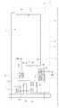
도 3은 본 발명의 제 1 실시예에 따른 듀얼패널타입 유기전계발광 소자에 대한 대한 단면도.3 is a cross-sectional view of a dual panel organic electroluminescent device according to a first embodiment of the present invention.
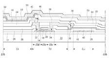
도 4a, 4b는 본 발명의 제 2 실시예에 따른 듀얼패널타입 유기전계발광 소자에 대한 도면으로서, 도 4a는 평면도이고, 도 4b는 상기 도 4a의 절단선 "IVb-IVb"에 따라 절단된 단면을 도시한 단면도.4A and 4B are views of the dual panel type organic light emitting display device according to the second embodiment of the present invention. FIG. 4A is a plan view and FIG. 4B is cut along the cutting line “IVb-IVb” of FIG. 4A. Cross section showing a cross section.
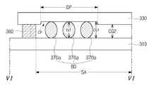
도 5, 도 6a 내지 6c는 본 발명의 제 3 실시예에 따른 듀얼패널타입 유기전계발광 소자에 대한 도면으로서, 도 5는 평면도이고, 도 6a 내지 6c는 상기 도 5의 절단선 "VI-VI"에 따라 절단된 단면을 도시한 각각의 단면도.5 and 6A to 6C are views of a dual panel type organic light emitting display device according to a third embodiment of the present invention. FIG. 5 is a plan view and FIGS. 6A to 6C are cut lines “VI-VI” of FIG. 5. Each cross-sectional view showing a cut cross section according to the invention.
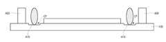
도 7a 내지 7f는 본 발명의 제 4 실시예에 따른 듀얼패널타입 유기전계발광 소자의 제조 공정을 단계별로 나타낸 공정 도면.7A to 7F are process diagrams illustrating step-by-step manufacturing processes of a dual panel type organic light emitting display device according to a fourth exemplary embodiment of the present invention.
<도면의 주요부분에 대한 부호의 설명><Description of Symbols for Main Parts of Drawings>
210 : 제 1 기판220 : 전기적 연결패턴210: first substrate 220: electrical connection pattern
230 : 제 2 기판236 : 컬러필터층230: second substrate 236: color filter layer
244 : 제 1 전극250 : 유기발광층244: first electrode 250: organic light emitting layer
252 : 제 2 전극260 : 씰패턴252: second electrode 260: seal pattern
270 : 바형 흡습제AA : 제 1 영역270: bar type absorbent AA: first region
CG1 : 오목부 이외의 제 2 영역의 셀갭CG1: cell gap in the second region other than the recessed portion
CG2 : 오목부에서의 셀갭CG2: cell gap in recess
CP : 오목부d1 : 바형 흡습제의 직경CP: recess d1: diameter of bar type | mold absorbent
DP : 흡습제 실장영역DP: Mounting Area of Hygroscopic
E : 유기전계발광 다이오드 소자E: organic light emitting diode device
T : 박막트랜지스터T: thin film transistor
본 발명은 유기전계발광 소자(Organic Electroluminescent Device)에 관한 것이며, 특히 특히 픽셀 구동부(박막트랜지스터를 포함하는 어레이 소자층)와 발광부(발광층을 포함하는 유기전계발광 다이오드 소자)가 서로 다른 기판에 형성되고, 두 소자는 별도의 전기적 연결패턴을 통해 연결되는 방식의 듀얼패널타입 유기전계 발광 소자(Active-Matrix Organic Electroluminescent Device) 및 그 제조방법에 관한 것이다.TECHNICAL FIELD The present invention relates to an organic electroluminescent device, and in particular, a pixel driver (array element layer including a thin film transistor) and a light emitting part (organic electroluminescent diode device including a light emitting layer) are formed on different substrates. The two devices are related to a dual panel type organic electroluminescent device (Active-Matrix Organic Electroluminescent Device) and a method of manufacturing the same, which are connected through separate electrical connection patterns.
새로운 평판디스플레이 중 하나인 유기전계발광 소자는 자체발광형이기 때문에 액정표시장치에 비해 시야각, 대조비 등이 우수하며 백라이트가 필요하지 않기 때문에 경량박형이 가능하고, 소비전력 측면에서도 유리하다. 그리고 직류저전압 구동이 가능하고 응답속도가 빠르며 전부 고체이기 때문에 외부충격에 강하고 사용온도범위도 넓으며 특히 제조비용 측면에서도 저렴한 장점을 가지고 있다.One of the new flat panel displays, the organic light emitting display device is self-luminous, and thus has a better viewing angle and contrast ratio than a liquid crystal display device. In addition, since it is possible to drive DC low voltage, fast response speed, and all solid, it is strong against external shock, wide use temperature range, and especially inexpensive in terms of manufacturing cost.
특히, 상기 유기전계발광 소자는 액정표시장치나 PDP(Plasma Display Panel)와 달리 공정이 매우 단순하기 때문에 증착 및 봉지(encapsulation) 장비가 전부라고 할 수 있다.In particular, since the organic light emitting device has a very simple process unlike a liquid crystal display device or a plasma display panel (PDP), deposition and encapsulation equipment are all.
이하, 도 1은 종래의 유기전계발광 소자 패널에 대한 단면도이다.1 is a cross-sectional view of a conventional organic light emitting device panel.
도시한 바와 같이, 제 1, 2 기판(10, 60)이 서로 대향되게 배치되어 있고, 제 1 기판(10) 상에는 화면을 구현하는 최소 단위인 화소 영역(P)별로 박막트랜지스터(T)를 포함하는 어레이 소자층(AL)이 형성되어 있으며, 상기 어레이 소자층(AL) 상부에는 제 1 전극(48), 유기발광층(54), 제 2 전극(56)이 차례대로 적층된 구조의 유기전계발광 다이오드 소자(E)가 형성되어 있다. 유기발광층(54)으로부터 발광된 빛은 제 1, 2 전극(48, 56) 중 투광성을 가지는 전극 쪽으로 발광되어, 상부발광 또는 하부발광 방식으로 분류할 수 있으며, 한 예로 제 1 전극(48)이 투광성 물질에서 선택되어 유기발광층(54)에서 발광된 빛이 제 1 전극(48)쪽으로 발광되는 하부발광 방식 구조를 제시하였다.As illustrated, the first and
그리고, 상기 제 2 기판(60)은 일종의 인캡슐레이션 기판으로서, 그 내부에는 오목부(62)가 형성되어 있고, 오목부(62) 내에는 외부로부터의 수분흡수를 차단하여 유기전계발광 다이오드 소자(E)를 보호하기 위한 흡습제(64)가 봉입되어 있다.In addition, the
상기 제 1, 2 기판(10, 60)의 가장자리부는 씰패턴(70)에 의해 봉지되어 있다.Edge portions of the first and
이하, 도 2a, 2b는 종래의 액티브 매트릭스형 유기전계발광 소자의 한 화소 영역에 대한 도면으로서, 도 2a는 평면도이고, 도 2b는 상기 도 2a의 절단선 "IIb-IIb"에 따라 절단된 단면을 도시한 단면도이며, 주요 구성요소를 중심으로 간략하게 설명한다.2A and 2B are views of one pixel area of a conventional active matrix organic electroluminescent device, and FIG. 2A is a plan view, and FIG. 2B is a cross section taken along the cutting line " IIb-IIb " This is a cross-sectional view showing a brief description of the main components.
도시한 바와 같이, 제 1 기판(10) 상에 버퍼층(12)이 형성되어 있고, 버퍼층(12) 상부에는 반도체층(14)과 커패시터 전극(16)이 서로 이격되게 형성되어 있으며, 상기 반도체층(14) 중앙부에는 게이트 절연막(18), 게이트 전극(20)이 차례대로 형성되어 있다. 상기 반도체층(14)은 게이트 전극(20)과 대응되는 활성 영역(IIc)과, 활성 영역(IIc)의 좌, 우 양측 영역은 드레인 영역(IId) 및 소스 영역(IIe)으로 각각 정의된다.As illustrated, a
상기 게이트 전극(20) 및 커패시터 전극(16)을 덮는 영역에는 제 1 보호층(24)이 형성되어 있으며, 제 1 보호층(24) 상부의 커패시터 전극(16)과 대응된 위치에는 파워 전극(26)을 포함하고, 상기 제 1 방향과 교차되는 제 2 방향으로 형성된 전력공급 배선(28)에서 분기되어 있다.A
상기 파워 전극(26)을 덮는 기판 전면에는 제 2 보호층(30)이 형성되어 있고, 상기 제 1, 2 보호층(24, 30)에는 공통적으로 반도체층(14)의 드레인 영역(IId)과 소스 영역(IIe)을 노출시키는 제 1, 2 콘택홀(32, 34)을 가지고 있고, 제 2 보호층(30)은 파워 전극(26)을 일부 노출시키는 제 3 콘택홀(36)을 가지고 있다.A
상기 제 2 보호층(30) 상부에는, 제 1 콘택홀(32)을 통해 반도체층(14)의 드레인 영역(IId)과 연결되는 드레인 전극(40)과, 일측에서는 제 2 콘택홀(34)을 통해 반도체층(14)의 소스 영역(IIe)과 연결되고, 또 다른 일측에서는 제 3 콘택홀(36)을 통해 파워 전극(26)과 연결되는 소스 전극(38)이 형성되어 있다.The
상기 드레인 전극(40) 및 소스 전극(38)을 덮는 영역에는, 드레인 전극(40)을 일부 노출시키는 드레인 콘택홀(46)을 가지는 제 3 보호층(44)이 형성되어 있다.In the region covering the
상기 제 3 보호층(44) 상부에는 발광부(EA)가 정의되어 있고, 발광부(EA)에는 드레인 콘택홀(46)을 통해 드레인 전극(40)과 연결되는 제 1 전극(48)이 형성되어 있으며, 제 1 전극(48) 상부에는 제 1 전극(48)의 주 영역을 노출시키며 그외 영역을 덮는 위치에 층간 절연막(50)이 형성되어 있고, 상기 층간 절연막(50) 상부의 발광부(EA)에는 유기발광층(54)이 형성되어 있고, 유기발광층(54) 상부 전면에는 제 2 전극(56)이 형성되어 있다.A light emitting part EA is defined on the
상기 반도체층(14), 게이트 전극(20), 소스 전극(38) 및 드레인 전극(40)은 박막트랜지스터(T)를 이루며, 상기 박막트랜지스터(T)는 상기 게이트 배선(22) 및 데이터 배선(42)이 교차되는 지점에 위치하는 스위칭 박막트랜지스터(Ts)와, 상기 스위칭 박막트랜지스터(Ts)와 전력공급 배선(28)이 교차되는 지점에 위치하는 구동 박막트랜지스터(Td)로 이루어진다.The
상기 도 2b에서 제시한 박막트랜지스터(T)는 구동 박막트랜지스터(Td)에 해당된다.The thin film transistor T shown in FIG. 2B corresponds to the driving thin film transistor Td.
즉, 전술한 게이트 전극(20)은 스위칭 박막트랜지스터(Ts)과 연결되고, 전술한 드레인 전극(40)은 아일랜드 패턴 구조로 이루어지며, 상기 게이트 배선(22) 및 데이터 배선(42)에서 분기되는 게이트 전극(20) 및 소스 전극(38)은 스위칭 박막트랜지스터(Ts)를 이룬다.That is, the above-described
상기 파워 전극(26)을 포함하여 전력공급 배선(28)과 커패시터 전극(16)이 중첩되는 영역은 스토리지 커패시턴스(Cst)를 이룬다.The region where the
상기 도 1, 도 2a, 2b를 통해 살펴본 바와 같이, 기존의 하부발광방식 유기전계발광 소자는 어레이 소자 및 유기전계발광 다이오드가 형성된 기판과 별도의 인캡슐레이션용 기판의 합착을 통해 소자를 제작하였다. 이런 경우, 어레이 소자의 수율과 유기전계발광 다이오드의 수율의 곱이 유기전계발광 소자의 수율을 결정하기 때문에, 기존의 유기전계발광 소자 구조에서는 후반 공정에 해당되는 유기전계발광 다이오드 공정에 의해 전체 공정 수율이 크게 제한되는 문제점이 있었다. 예를 들어, 어레이 소자가 양호하게 형성되었다 하더라도, 1,000 Å 정도의 박막을 사용하는 유기발광층의 형성시 이물이나 기타 다른 요소에 의해 불량이 발생하게 되면, 유기전계발광 소자는 불량 등급으로 판정된다.As described with reference to FIGS. 1, 2A, and 2B, the conventional bottom emission type organic light emitting diode device is manufactured by bonding an array device and a substrate on which an organic light emitting diode is formed and a separate encapsulation substrate. . In this case, since the product of the yield of the array device and the yield of the organic light emitting diode determines the yield of the organic light emitting diode, the overall organic process of the organic light emitting diode structure yields the overall process yield by the organic electroluminescent diode process. There was a problem that is greatly limited. For example, even if the array element is satisfactorily formed, if a defect occurs due to foreign matter or other elements in the formation of the organic light emitting layer using a thin film of about 1,000 GPa, the organic electroluminescent element is determined to be a poor grade.
이로 인하여, 양품의 어레이 소자를 제조하는데 소요되었던 제반 경비 및 재료비 손실이 초래되고, 생산수율이 저하되는 문제점이 있었다.This results in a loss of overall costs and material costs that were required to manufacture the array device of good quality, there was a problem that the production yield is lowered.
그리고, 하부발광방식은 인캡슐레이션에 의한 안정성 및 공정이 자유도가 높은 반면 개구율의 제한이 있어 고해상도 제품에 적용하기 어려운 문제점이 있고, 상부발광방식은 박막트랜지스터 설계가 용이하고 개구율 향상이 가능하기 때문에 제품수명 측면에서 유리하지만, 기존의 상부발광방식 구조에서는 유기발광층 상부에 통상적으로 음극이 위치함에 따라 재료선택폭이 좁기 때문에 투과도가 제한되어 광효율이 저하되는 점과, 광투과도의 저하를 최소화하기 위해 박막형 보호막을 구성해야 하는 경우 외기를 충분히 차단하지 못하는 문제점이 있었다.In addition, the bottom emission method has a high degree of freedom and stability due to the encapsulation process, and has a problem in that it is difficult to be applied to a high-resolution product due to the limitation of the aperture ratio. In terms of product life, the conventional top emission type structure has a narrow material selection range as the cathode is generally located on the organic light emitting layer, so the transmittance is limited and the light efficiency is reduced. When the thin film protection film should be configured, there is a problem in that it does not sufficiently block outside air.
상기 문제점을 해결하기 위하여, 본 발명에서는 생산수율이 향상된 고해상도/고개구율 구조 액티브 매트릭스형 유기전계발광 소자를 제공하고자 한다.In order to solve the above problems, the present invention is to provide a high-resolution / high aperture structure active matrix organic electroluminescent device with improved production yield.
이를 위하여, 본 발명에서는 픽셀 구동부(박막트랜지스터를 포함하는 어레이 소자층)와 발광부(발광층을 포함하는 유기전계발광 다이오드 소자)가 서로 다른 기판에 형성되고, 두 소자는 별도의 전기적 연결패턴을 통해 연결되는 방식의 듀얼패널타입 유기전계발광 소자를 제공하고자 한다.To this end, in the present invention, the pixel driver (array element layer including a thin film transistor) and the light emitting unit (organic electroluminescent diode device including a light emitting layer) are formed on different substrates, and the two devices are formed through separate electrical connection patterns. An object of the present invention is to provide a dual panel type OLED.
본 발명의 또 다른 목적은, 별도의 흡습제 실장공간을 생략하면서도 소자 내부의 수분을 효과적으로 제거할 수 있는 구조의 흡습제를 포함하는 듀얼패널타입 유기전계발광 소자 및 그 제조방법의 제공으로, 신뢰성 확보, 수명 및 내구성 향 상, 제품 안정성을 확보하고자 한다.Still another object of the present invention is to provide a dual panel type organic light emitting display device and a method of manufacturing the same, including a moisture absorbent having a structure capable of effectively removing moisture inside the device while eliminating a separate absorbent mounting space, thereby ensuring reliability. To improve life and durability, and to ensure product stability.
이를 위하여, 본 발명에서는 화면 구현 영역과 씰패턴 형성부 사이 구간에 바(bar)형 흡습제를 구비하며, 특히 바형 흡습제의 안정적인 고정을 위하여 어느 한 기판면의 흡습제와 접촉된 면에 식각부를 형성하고자 한다.
To this end, the present invention is provided with a bar (bar) absorbent in the section between the screen realization region and the seal pattern forming portion, in particular to form an etching portion on the surface in contact with the absorbent on any one substrate surface for the stable fixing of the bar-shaped absorbent do.
상기 목적을 달성하기 위하여, 본 발명의 제 1 특징에서는, 제 1 기판 상에 형성되며, 박막트랜지스터를 포함하는 어레이 소자층과; 상기 박막트랜지스터와 연결되며, 상기 어레이 소자층 상부에서 일정 두께를 갖는 전기적 연결패턴과; 상기 제 1 기판과 대향되는 제 2 기판 하부에 형성되며, 상기 전기적 연결패턴과 연결되는 유기전계발광 다이오드 소자와; 상기 제 1, 2 기판의 테두리부에 위치하는 씰패턴과; 상기 전기적 연결패턴에 의한 전류 공급에 의해 화면을 구현하는 영역은 제 1 영역을 이루고, 상기 씰패턴과 제 1 영역 사이 구간에 위치하는 제 2 영역에 서로 이격하며 형성된 다중의 바(bar)형 흡습제와; 상기 다중의 바(bar)형 흡습제와 접촉되는 제 1, 2 기판면 중 어느 한 기판면에 형성된 오목부를 포함하며, 상기 오목부 형성부는 흡습제 실장영역을 이루는 것을 특징으로 하는 듀얼패널타입 유기전계발광 소자를 제공한다.In order to achieve the above object, in a first aspect of the present invention, an array element layer is formed on a first substrate and includes a thin film transistor; An electrical connection pattern connected to the thin film transistor and having a predetermined thickness on the array element layer; An organic light emitting diode device formed under the second substrate facing the first substrate and connected to the electrical connection pattern; Seal patterns positioned on edge portions of the first and second substrates; A region implementing the screen by supplying current by the electrical connection pattern forms a first region, and a plurality of bar-type absorbents formed spaced apart from each other in a second region located in a section between the seal pattern and the first region. Wow; A dual panel type organic light emitting display device comprising a recess formed in one of the first and second substrate surfaces in contact with the plurality of bar-type absorbents, and the recess forming portion forms an absorbent mounting region. Provided is an element.
상기 다중의 바(bar)형 흡습제의 높이는, 상기 오목부에서의 셀갭보다 작거나 대응되는 값에서 선택되고, 상기 다중의 바(bar)형 흡습제의 높이는, 상기 오목부 이외의 제 2 영역이 가지는 셀갭보다는 큰 값을 가지는 것을 특징으로 한다.The height of the multiple bar absorbents is selected from a value smaller than or corresponding to a cell gap in the recess, and the height of the multiple bar absorbents is included in a second region other than the recesses. It is characterized by having a larger value than the cell gap.
그리고, 상기 다중의 바(bar)형 흡습제의 단면 구조는 원형, 사각형, 사다리꼴 중 어느 한 형태로 이루어지고, 상기 제 2 기판의 어느 한 제 2 영역은, 외부회로 연결영역을 포함하고, 상기 흡습제 실장영역은 상기 외부회로 연결영역을 제외한 영역에서 구성되는 것을 특징으로 한다.The cross-sectional structure of the multiple bar absorbents may be one of circular, rectangular, and trapezoidal shapes, and any one second region of the second substrate may include an external circuit connection region. The mounting area may be configured in an area excluding the external circuit connection area.
상기 어레이 소자층은, 상기 박막트랜지스터에 전압을 인가하는 다수개의 게이트 배선, 데이터 배선, 파워 배선을 포함하고, 상기 박막트랜지스터는, 상기 게이트 배선 및 데이터 배선에서 인가되는 전압을 제어하는 스위칭 박막트랜지스터와, 상기 스위칭 박막트랜지스터의 어느 한 구동 전극 및 상기 파워 배선에서 인가되는 전압을 이용하여 발광 휘도를 조절하는 구동 박막트랜지스터로 이루어지며, 상기 전기적 연결패턴과 연결되는 실질적인 박막트랜지스터는 구동 박막트랜지스터인 것을 특징으로 한다.The array element layer includes a plurality of gate wirings, data wirings, and power wirings for applying a voltage to the thin film transistor, and the thin film transistor includes: a switching thin film transistor for controlling a voltage applied from the gate wiring and the data wiring; And a driving thin film transistor for controlling light emission luminance by using a driving electrode of the switching thin film transistor and a voltage applied from the power line, wherein the substantially thin film transistor connected to the electrical connection pattern is a driving thin film transistor. It is done.
상기 유기전계발광 다이오드 소자는, 상기 제 2 기판 전면에 형성된 제 1 전극과, 상기 제 1 전극 하부에서 화면을 구현하는 최소 단위인 화소 영역별로 차례대로 형성된 유기발광층 및 제 2 전극으로 이루어지고, 상기 유기발광층은, 화소 영역별로 적, 녹, 청 발광층이 차례대로 배열된 구조로 이루어지거나, 또는 상기 유기발광층은 단색 발광층으로 이루어지고, 상기 제 2 기판과 유기전계발광 다이오드 소자 사이에는, 컬러필터층 단일 구조 또는 컬러필터층 및 색변환층인 CCM(color changing mediums)으로 이루어진 이중 구조로 이루어진 별도의 풀컬러 구현소자를 더 포함하는 것을 특징으로 한다.The organic light emitting diode device includes a first electrode formed on the front surface of the second substrate, an organic light emitting layer and a second electrode sequentially formed for each pixel region that is a minimum unit that implements a screen under the first electrode. The organic light emitting layer has a structure in which red, green, and blue light emitting layers are arranged in sequence for each pixel area, or the organic light emitting layer is made of a single color light emitting layer, and a single color filter layer is disposed between the second substrate and the organic light emitting diode device. It is characterized in that it further comprises a separate full-color implementation element consisting of a dual structure consisting of a structure or a color filter layer and a color converting layer (CCM).
본 발명의 제 2 특징에서는, 화면을 구현하는 제 1 영역과, 상기 제 1 영역 외측으로 제 2 영역이 정의된 제 1, 2 기판을 구비하는 단계와; 상기 제 1 기판의 제 1 영역에 박막트랜지스터 및 상기 박막트랜지스터와 연결되는 어레이 소자층을 형성하는 단계와; 상기 제 2 기판의 제 1 영역에 유기전계발광 다이오드를 형성하는 단계와; 상기 어레이 소자층 상에 상기 어레이 소자층과 상기 유기전계발광 다이오드를 전기적으로 연결시키는 전기적 연결패턴을 형성하는 단계와; 상기 제 1, 2 기판 중 선택된 기판의 상기 제 2 영역에 대응하여 에천트를 이용한 습식식각법에 의해 상기 선택된 기판면을 식각처리하여 오목부를 형성하는 단계와; 상기 오목부 상에 바(bar)형 흡습제를 안치하는 단계와; 상기 바(bar)형 흡습제 바깥쪽 테두리부에 씰패턴을 형성하는 단계와; 상기 바(bar)형 흡습제가 안치된 기판을 하부 기판으로 하여, 상기 제 1, 2 기판을 합착하는 단계를 포함하는 듀얼패널타입 유기전계발광 소자의 제조 방법을 제공한다.According to a second aspect of the present invention, there is provided a method comprising: providing a first area for implementing a screen and first and second substrates having a second area defined outside the first area; Forming a thin film transistor and an array element layer connected to the thin film transistor in a first region of the first substrate; Forming an organic light emitting diode in a first region of the second substrate; Forming an electrical connection pattern on the array element layer to electrically connect the array element layer and the organic light emitting diode; Forming a recess by etching the surface of the selected substrate by a wet etching method using an etchant corresponding to the second region of the selected substrate among the first and second substrates; Placing a bar absorbent on the recess; Forming a seal pattern on an outer edge of the bar type absorbent; It provides a method of manufacturing a dual panel type organic electroluminescent device comprising the step of bonding the first and second substrates, the substrate having the bar-shaped absorbent is placed as a lower substrate.
상기 오목부를 형성하는 단계에서, 에천트를 이용한 습식식각법에 의해 베이스 기판면을 식각처리하는 단계를 포함하고, 상기 에천트는 불산(HF) 또는 질산(HNO3) 중 어느 하나에서 선택되며, 상기 바형 흡습제를 안치하는 단계에서, 상기 바형 흡습제의 높이는, 상기 오목부에서의 셀갭보다 작거나 대응된 값에서 선택되고, 상기 바형 흡습제의 높이는, 상기 오목부 이외의 제 2 영역이 가지는 셀갭보다는 큰 값에서 선택되며, 상기 오목부를 형성하는 단계에서, 상기 오목부는, 상기 제 2 기판의 외부회로 연결 영역 이외의 제 2 영역 범위에 형성하는 것을 특징으로 한다. 상기 바형 흡습제의 단면 구조는 원형, 사각형, 사다리꼴 중 어느 한 형태로 이루어지고, 상기 바형 흡습제를 이루는 물질은, 흡습성을 가지는 산화계 물질에서 선택되며, 상기 오목부가 형성되는 기판은 제 2 기판인 것을 특징으로 한다.In the forming of the concave portion, the step of etching the base substrate surface by a wet etching method using an etchant, the etchant is selected from any one of hydrofluoric acid (HF) or nitric acid (HNO3 ), the In the step of placing the bar-shaped absorbent, the height of the bar-shaped absorbent is selected from a value smaller than or corresponding to the cell gap in the recess, and the height of the bar-type absorbent is larger than the cell gap of the second region other than the recess. In the step of forming the recess, the recess, characterized in that formed in the second region range other than the external circuit connection region of the second substrate. The cross-sectional structure of the bar-shaped absorbent is made of any one of circular, rectangular, trapezoidal, the material forming the bar-shaped absorbent is selected from an oxidizing material having hygroscopicity, the substrate on which the recess is formed is a second substrate It is done.
이하, 본 발명에 따른 바람직한 실시예에 대해서 도면을 참조하여 상세히 설명한다.Hereinafter, exemplary embodiments of the present invention will be described in detail with reference to the accompanying drawings.
본 발명에 따른 하나의 실시예는, 풀컬러 구현소자를 포함하는 듀얼패널타입 유기전계발광 소자에 대한 실시예이다.One embodiment according to the present invention is an embodiment for a dual panel type organic electroluminescent device including a full color device.
유기전계발광 소자에서 풀컬러 구현을 위해서는, 별도의 컬러필터층으로 이루어진 단일 구조 또는, 컬러필터층 및 색변환층인 CCM(Color-changing Mediums)으로 이루어진 이중 구조와, 단색 발광물질로 이루어진 유기발광층을 포함하거나, 또는 유기발광층을 적, 녹, 청 발광층으로 구성하여 독립적인 발광방식으로 구동될 수도 있다.In order to implement full color in an organic light emitting device, a single structure consisting of a separate color filter layer or a dual structure consisting of a color filter layer and a color conversion layer (CCM), a color conversion layer, and an organic light emitting layer made of a single color light emitting material are included. Alternatively, the organic light emitting layer may be composed of red, green, and blue light emitting layers, and may be driven by an independent light emitting method.
이 중에서, 본 발명에 따른 듀얼패널타입 유기전계발광 소자는, 별도의 풀컬러 구현소자와 단색 발광물질로 이루어지는 유기발광층과, 상기 풀컬러 구현소자의 평탄화 특성을 위한 평탄화층을 주요 구성요소로 포함한다.Among these, the dual panel type organic electroluminescent device according to the present invention includes an organic light emitting layer made of a separate full color implementation element and a monochromatic light emitting material, and a planarization layer for planarization characteristics of the full color implementation element as main components. do.
-- 제 1 실시예 --First Embodiment
도 3은 본 발명의 제 1 실시예에 따른 듀얼패널타입 유기전계발광 소자에 대한 단면도이다.3 is a cross-sectional view of a dual panel type organic light emitting display device according to a first embodiment of the present invention.
도시한 바와 같이, 제 1, 2 기판(110, 130)이 서로 대향되게 배치되어 있고, 제 1 기판(110) 상부에는 박막트랜지스터(T)를 포함하는 어레이 소자층(A)이 형성되어 있으며, 어레이 소자층(A) 상부에는 일정 두께를 가지며, 상기 박막트랜지스터(T)와 연결되는 전기적 연결패턴(120)이 형성되어 있다. 한 예로, 상기 전기적 연결패턴(120)은, 두께감을 주기위한 유기절연 패턴을 포함하여 다중층 구조로 형 성될 수 있다.As illustrated, the first and
한 예로, 상기 박막트랜지스터(T)는 비정질 실리콘을 반도체 물질로 이용하며, 탑게이트 방식(top gate type)보다 공정 효율면에서 우수한 버텀게이트 방식(bottom gate type) 구조로 제시하였다. 그러나, 본 발명에 따른 박막트랜지스터(T)는 버텀게이트 방식으로 한정되는 것은 아니고, 탑게이트 방식의 적용도 무방하다.As an example, the thin film transistor T uses amorphous silicon as a semiconductor material and has a bottom gate type structure having better process efficiency than a top gate type. However, the thin film transistor T according to the present invention is not limited to the bottom gate method, and the top gate method may be applied.
그리고, 도면으로 상세히 제시하지 않았지만, 상기 어레이 소자층(A)은 외부회로로부터 신호전압을 인가받는 다수 개의 게이트 배선, 데이터 배선, 파워 배선을 포함한다.Although not shown in detail in the drawings, the array element layer A includes a plurality of gate wirings, data wirings, and power wirings to which a signal voltage is applied from an external circuit.
상기 전기적 연결패턴(120)과 연결되는 박막트랜지스터(T)는 발광 휘도 조절을 위한 구동 박막트랜지스터에 해당된다.The thin film transistor T connected to the
그리고, 상기 제 2 기판(130) 하부에는 풀컬러 구현소자인 컬러필터층(136)이 형성되어 있고, 컬러필터층(136) 하부에는 평탄화를 목적으로 평탄화층(140)이 형성되어 있다. 상기 컬러필터층(136)은 화소 영역(P)별로 차례대로 위치하는 적, 녹, 청 컬러필터(132a, 132b, 132c)와, 적, 녹, 청 컬러필터(132a, 132b, 132c) 사이 구간을 포함하여 화소 영역(P) 간 이격 영역인 비화소 영역(NP ; non-pixel area)에 위치하는 블랙매트릭스(134)로 이루어지고, 상기 평탄화층(140)은 평탄화 특성이 우수한 절연물질에서 선택되며, 한 예로 유기물질에서 선택될 수 있다.A
그리고, 상기 평탄화층(140) 하부에는, 컬러필터층(136)으로부터의 탈기체를 방지하기 위한 베리어층(142 ; barrier layer)이 형성되어 있고, 베리어층(142) 하 부에는 제 1 전극(144)이 형성되어 있으며, 제 1 전극(144) 하부의 비화소 영역(NP)에는 층간절연막(146)과, 역테이퍼 구조로 일정두께를 갖는 격벽(148)이 차례대로 형성되어 있고, 격벽(148) 하부에는 격벽(148)에 의해 자동 패터닝되어 화소 영역(P) 별로 분리된 구조로 유기발광층(150), 제 2 전극(152)이 차례대로 형성되어 있다.A
상기 제 1 전극(144), 유기발광층(150), 제 2 전극(152)은 유기전계발광 다이오드 소자(E)를 이룬다.The
그리고, 상기 제 2 전극(152)은 전기적 연결패턴(120)과 연결되어 있어서, 상기 박막트랜지스터(T)에서 공급되는 전류는 전기적 연결패턴(120)을 통해 제 2 전극(152)으로 인가된다.In addition, since the
상기 제 1 전극(144)은 투광성을 가지는 물질에서 선택되어, 유기발광층(150)에서 발광된 빛은 제 1 전극(144)쪽으로 발광되는 상부발광 방식으로 화면을 구현하는 것을 특징으로 한다. 한 예로, 상기 제 1 전극(144)이 양극(anode electrode), 제 2 전극(152)이 음극(cathode electrode)에 해당될 경우, 제 1 전극(144)은 투명 도전성 물질에서 선택되고, 대표적인 예로 ITO(indium tin oxide)로 이루어질 수 있다.The
그리고, 상기 제 1, 2 기판(110, 130)의 가장자리부는 씰패턴(160)에 의해 봉지되어 있다.The edges of the first and
도면으로 제시하지 않았지만, 본 발명에서는 풀컬러 구현소자는 컬러필터층과, 컬러필터층과 평탄화층 사이에 색변환층인 CCM(color-changing mediums)로 이 루어질 수 있다.Although not shown in the drawings, the full-color implementation element may be formed of a color filter layer and color-changing mediums (CCMs) that are color conversion layers between the color filter layer and the planarization layer.
본 실시예와 같이 별도의 풀컬러 구현소자가 구비되는 경우, 유기발광층은 단색 발광층으로 이루어지며, 특히 풀컬러 구현소자 중에서 컬러필터층 단일 구조가 적용될 경우, 유기발광층은 백색 발광층으로 구성되고, 컬러필터층 및 CCM 이중 구조가 적용될 경우 유기발광층은 청색(스카이 블루(sky blue) 또는 그리니쉬 블루(greenish blue)) 발광층으로 구성될 수 있다.When a separate full color implementation element is provided as in this embodiment, the organic light emitting layer is formed of a single color light emitting layer, and in particular, when a single color filter layer is applied among the full color implementation elements, the organic light emitting layer is composed of a white light emitting layer, and the color filter layer. And when the CCM double structure is applied, the organic light emitting layer may be composed of a blue (sky blue or greenish blue) light emitting layer.
이러한 듀얼패널타입 유기전계발광 소자에 의하면, 픽셀 구동부와 발광부를 서로 독립적으로 서로 다른 기판에 형성하기 때문에, 제품의 신뢰성 및 생산성을 향상시킬 수 있으며, 제품수명을 효과적으로 늘릴 수 있으며, 박막트랜지스터 설계가 용이해지고 고개구율/고해상도 구현이 가능한 장점을 가지게 된다.According to the dual panel organic light emitting device, since the pixel driver and the light emitting unit are formed on different substrates independently of each other, the reliability and productivity of the product can be improved, the product life can be effectively increased, and the thin film transistor design It has the advantage of being easy and high aperture ratio / high resolution.
그러나, 종래의 유기전계발광 소자와 비교해서, 듀얼패널타입 유기전계발광 소자 패널의 단점은 패널 내부의 수분을 흡수하는 흡습제 실장 공간이 별도로 구비할 수 없다는 것이다.However, the disadvantage of the dual panel type organic electroluminescent device panel, compared with the conventional organic light emitting device, is that the absorbent mounting space for absorbing moisture inside the panel cannot be provided separately.
좀 더 구체적으로 설명하면, 종래의 유기전계발광 소자에서는 상부 기판에 별도의 소자가 형성되지 않기 때문에, 상부 기판의 내부면에 흡습제를 인입하는 구조로 흡습 기능이 갖추어졌으나, 듀얼패널의 경우 상부 및 하부 기판에 각각 소자 들이 형성되기 때문에 별도로 흡습제를 구비할 여유 공간을 갖추지 못하는 단점이 있다.More specifically, in the conventional organic electroluminescent device, since a separate device is not formed on the upper substrate, a moisture absorption function is provided by introducing a moisture absorbent into the inner surface of the upper substrate. Since each element is formed on the lower substrate, there is a disadvantage in that it does not have a free space to have a moisture absorbent separately.
이하, 본 발명의 또 하나의 실시예는 별도의 흡습제 실장 공간의 구비없이도 소자 내부의 수분을 제거할 수 있는 흡습제를 포함하는 구조에 대한 실시예이다.Hereinafter, another embodiment of the present invention is an embodiment for a structure including a moisture absorbent capable of removing moisture inside the device without providing a separate absorbent mounting space.
종래의 유기전계발광 소자의 경우, 상부 기판에 별도의 소자가 구성되지 않으므로, 흡습제를 안치할 공간이 충분하였다. 그래서, 종래의 경우 상부 기판에 대략 20 ㎜ 이상 너비의 식각 공간(오목부)를 확보하여 가공할 수 있었다.In the conventional organic electroluminescent device, since a separate device is not configured on the upper substrate, there is sufficient space for placing the moisture absorbent. Therefore, in the related art, an etching space (concave portion) having a width of approximately 20 mm or more on the upper substrate can be secured and processed.
그러나, 듀얼패널타입 구조의 경우 각각의 기판에 픽셀 구동소자 및 발광 소자가 형성되기 때문에 제약을 받게 되고, 또한 패널의 비액티브 영역을 최소화하기 위해 오목부를 최소한의 폭으로 형성할 필요가 있다. 한 예로 최대로 가질 수 있는 폭은 5 ㎜로 폭이 작으면 작을수록 패널은 발광 이외의 영역을 최소화될 수 있기 때문에, 가공의 정밀도가 필요하다.However, the dual panel type structure is restricted because the pixel driving element and the light emitting element are formed on each substrate, and it is necessary to form the concave portion with the minimum width in order to minimize the inactive area of the panel. As an example, the maximum width is 5 mm, and the smaller the width, the smaller the width of the panel can be to minimize the area other than the light emission, the processing precision is required.
이러한 경우, 종래의 흡습제는 흡습부와 기판과의 접합을 시키기 위한 접합부가 있어, 흡습제 자체의 가공 정밀도가 얻기 힘들고, 또한 흡습제 안치할 충분한 공간이 없게 되고 만다.In such a case, the conventional moisture absorbent has a bonding portion for bonding the moisture absorbing portion to the substrate, so that the processing accuracy of the moisture absorbent itself is hard to be obtained, and there is no sufficient space for the moisture absorbent to be placed.
그리고, 기판을 식각하기 위해서는 대부분 에천트(etchant)를 이용하는 습식식각(wet etching)을 이용하기 때문에, 등방성 식각이 이루어져 충분히 깊은 오목부를 구현하기가 공정 상 어렵다. 이러한 특성 때문에 종래의 흡습제 대신에 가는 실형태(로드(rod) 형태) 또는 로드 형태로 가공하여 이를 오목부에 안치하고 상판과 하판을 합착시키게 되면 오목부에서의 셀갭차에 의해 흡습제를 지지 또는 고정하는 형태를 가질 수 있다.In addition, in order to etch the substrate, since wet etching using an etchant is mostly used, an isotropic etching is performed, so that it is difficult to realize a deep enough recess. Due to these characteristics, when the mold is processed into a thin thread (rod form) or rod form instead of the conventional absorbent and placed in the recess, and the upper and lower plates are joined, the absorbent is supported or fixed by the cell gap difference in the recess. It may have a form.
단, 흡습제의 직경 또는 크기는 합착 후의 오목부에서의 셀갭보다 작고, 그외 셀갭 영역에서보다는 큰 값을 가져야 한다.However, the diameter or size of the moisture absorbent should be smaller than the cell gap in the recessed portion after bonding, and larger than in the other cell gap regions.
-- 제 2 실시예 --Second Embodiment
도 4a, 4b는 본 발명의 제 2 실시예에 따른 듀얼패널타입 유기전계발광 소자에 대한 도면으로서, 도 4a는 평면도이고, 도 4b는 상기 도 4a의 절단선 "IVb-IVb"에 따라 절단된 단면을 도시한 단면도이다.4A and 4B are views of the dual panel type organic light emitting display device according to the second embodiment of the present invention. FIG. 4A is a plan view and FIG. 4B is cut along the cutting line “IVb-IVb” of FIG. 4A. It is sectional drawing which shows the cross section.
도시한 바와 같이, 제 1, 2 기판(210, 230)이 서로 대향되게 배치되어 있고, 제 1 기판(210) 상에는 박막트랜지스터(T)를 포함하는 어레이 소자층(A)이 형성되어 있으며, 상기 박막트랜지스터(T)와 연결되어 어레이 소자층(A) 상부에는 일정두께를 가지는 전기적 연결패턴(220)이 형성되어 있다.As illustrated, the first and
그리고, 상기 제 2 기판(230) 하부에는 풀컬러 구현소자의 일 예로써 컬러필터층(236)을 포함하고, 그 하부에는 제 1 전극(244), 유기발광층(250), 제 2 전극(252)으로 이루어진 유기전계발광 다이오드 소자(E)가 형성되어 있다.In addition, a
그러나, 본 발명은 풀컬러 구현소자로서 컬러필터층 및 CCM 이중 구조 또는, 유기발광층(250)을 적, 녹, 청 발광층으로 이루어진 독립발광방식으로 구성하고, 별도의 풀컬러 구현소자를 생략한 구조 또한 포함한다.However, according to the present invention, the color filter layer and the CCM dual structure or the organic
상기 제 1, 2 기판(210, 230)의 테두리부에는 씰패턴(260)이 형성되어 있다.
상기 씰패턴(260) 내부 영역은, 상기 전기적 연결패턴(220)과의 연결관계에 의해 유기발광층(250)을 발광시킬 수 있는 영역, 즉 화면을 구현하는 영역인 제 1 영역(AA ; active area)과, 제 1 영역(AA)과 씰패턴(260) 형성부 사이에 위치하는 제 2 영역(SA ; active side area)으로 정의할 수 있다.The inner region of the
본 실시예에서는, 상기 제 2 영역(SA)에 흡습제 실장영역(DP ; descicant packaging area)이 위치하며, 한 예로 흡습제 실장영역(DP)은 제 2 기판(230)과 외부회로 연결영역(CA ; external circuit connecting area)을 제외한 영역범위에 위치하는 것이 바람직하다.In the present exemplary embodiment, a descicant packaging area (DP) is positioned in the second area SA. For example, the descicant packaging area DP may include a
상기 흡습제 실장영역(DP) 내에는 바형 흡습제(270)가 구비되어 있고, 바형 흡습제(270)와 접촉되는 제 2 기판(230) 내부면은, 상기 바형 흡습제(270)의 위치 고정을 위하여 오목부(CP ; concave part)가 형성되어 있다.The
그러나, 본 발명에 따른 바형 흡습제(270)의 평면 구조는, 제 2 기판(230)의 제 1 전극(244)과 제 1 기판(210)의 패드부간의 연결부를 고려하여 다양하게 변경가능하며, 단, 바형 흡습제(270)의 기본적인 단면 구조는 도 4b에서 나타낸 원형 구조를 기본 구조로 한다.However, the planar structure of the
상기 제 1, 2 기판 간의 셀갭(CG ; cell gap), 구체적으로는 흡습제 실장영역(DP) 이외의 제 2 영역(SA)에서의 기판 간의 셀갭을 "CG1"이라고 했을 때, 상기 오목부(CP)에서의 셀갭인 "CG2"는 "CG1"보다 큰 값을 가지고, 상기 오목부(CP) 내에 위치하는 바형 흡습제(270)의 직경(d1 ; diameter)은, 흡습제(270)의 안정적인 고정과 셀갭 안정성을 고려하여, "CG1"보다는 크고, "CG2"와 대응되거나 작은 값에서 선택되는 것을 특징으로 한다.When the cell gap (CG) between the first and second substrates, specifically, the cell gap between the substrates in the second region SA other than the moisture absorbent mounting region DP, is referred to as "CG1", the concave portion CP ), The cell gap "CG2" has a larger value than "CG1", and the diameter d1 of the bar-shaped moisture absorbent 270 located in the recess CP is a stable fixation of the
이하, 본 발명의 또 다른 실시예는, 바형 흡습제의 단면 구조 및 갯수를 변형한 실시예이다.Hereinafter, another Example of this invention is an Example which modified the cross-sectional structure and number of bar type moisture absorbers.
-- 제 3 실시예 --Third Embodiment
도 5, 도 6a 내지 6c는 본 발명의 제 3 실시예에 따른 듀얼패널타입 유기전 계발광 소자에 대한 도면으로서, 도 5는 평면도이고, 도 6a 내지 6c는 상기 도 5의 절단선 "VI-VI"에 따라 절단된 단면을 도시한 각각의 단면도로서, 도 6a는 원형 단면구조, 도 6b는 사각형 단면구조, 도 6c는 사다리꼴 단면 구조에 대한 것이다.5 and 6A to 6C are views of a dual panel type organic light emitting display device according to a third exemplary embodiment of the present invention. FIG. 5 is a plan view, and FIGS. 6A to 6C are cut lines “VI-” of FIG. 5. Each cross-sectional view showing a cross section taken along line VI ″, where FIG. 6A is a circular cross-sectional structure, FIG. 6B is a rectangular cross-sectional structure, and FIG. 6C is a trapezoidal cross-sectional structure.
설명의 편의상, 도 5에서는 바형 흡습제를 포함하는 제 2 영역과 씰패턴 형성부 일부 영역을 중심으로 도시하였다.For convenience of description, in FIG. 5, the second region including the bar absorbent and the partial region of the seal pattern forming unit are illustrated.
도시한 바와 같이, 제 1, 2 기판(310, 330)이 서로 일정간격 이격된 상태에서 대향되어 있고, 상기 제 1, 2 기판(310, 330)의 가장자리부에는 씰패턴(360)이 형성되어 있는 구조에서, 상기 씰패턴(360) 내부의 제 2 영역(SA)에는 흡습제 실장영역(DP ; descicant packaging area)을 포함하고 있다.As shown, the first and
상기 흡습제 실장영역(DP)에는, 상기 제 2 기판(330)에는 오목부(CP)가 형성되어 있고, 오목부(CP) 내에는 바형 흡습제(BD ; bar type descicant)가 다수 개 배치되어 있다.In the moisture absorbent mounting region DP, recesses CP are formed in the
상기 바형 흡습제(BD)의 높이(h1, h2, h3)는, 상기 오목부(CP)에서의 셀갭(CG2)과 대응되거나 작은 값을 가지고, 흡습제 실장영역(DP)이외의 제 2 영역(SA)이 가지는 셀갭(CG1)보다는 큰 값을 가진다.The heights h1, h2, and h3 of the bar-shaped moisture absorbent BD have a value corresponding to or smaller than the cell gap CG2 in the recess CP, and have a second area SA other than the moisture absorbent mounting region DP. ) Has a larger value than the cell gap CG1.
도 6a는, 전술한 다수 개의 바형 흡습제(370a)의 단면이 원형구조임을 나타낸 것이고, 도 6b는 사각형 구조의 바형 흡습제(370b), 도 6c는 상광하협(上廣下狹)의 사다리꼴 구조의 바형 흡습제(370c)에 대해서 도시하였고, 이와 같이 본 실시예에 따른 다수 개의 바형 흡습제(BD)는 다양한 단면 구조를 가질 수 있음을 제시하였다.FIG. 6A illustrates that the cross-sections of the plurality of bar-shaped
그리고, 상기 도 6a 내지 6c에 따른 다양한 단면구조를 가지는 흡습제는 다음과 같은 조건을 만족한다.In addition, the moisture absorbent having various cross-sectional structures according to FIGS. 6A to 6C satisfies the following conditions.
1) 바형 흡습제가 차지하는 너비는, 상기 오목부 너비보다 작거나 동일하다.1) The width occupied by the bar absorbent is smaller than or equal to the width of the recess.
2) 바형 흡습제의 높이는, 상기 오목부에서의 셀갭보다 작거나 동일하고, 그외 제 1, 2 기판의 셀갭보다는 큰 값을 가진다.2) The height of the bar-shaped moisture absorbent is smaller than or equal to the cell gap in the concave portion, and has a larger value than the cell gap of the first and second substrates.
이하, 본 발명의 또 다른 실시예에서는, 상기 바형 흡습제을 포함한 듀얼패널타입 유기전계발광 소자의 제조 공정에 대한 실시예이다.Hereinafter, in another embodiment of the present invention, an embodiment of the manufacturing process of the dual panel organic electroluminescent device including the bar-type moisture absorbent.
-- 제 4 실시예 --Fourth Embodiment
도 7a 내지 7f는 본 발명의 제 4 실시예에 따른 듀얼패널타입 유기전계발광 소자의 제조 공정을 단계별로 나타낸 공정 도면으로서, 바형 흡습제의 제조 공정을 중심으로 설명하기 위하여, 픽셀 구동부 소자와 발광부 소자에 대한 도시는 모식적으로 간략하게 도시하였다.7A to 7F are process steps illustrating a step of manufacturing a dual panel type organic light emitting display device according to a fourth exemplary embodiment of the present invention. In order to focus on the manufacturing process of a bar absorbent, a pixel driving device and a light emitting part may be described. The illustration of the device is schematically illustrated briefly.
도 7a는, 제 1 기판(410) 상에 픽셀 구동부(PD ; pixel driving part)와, 상기 픽셀 구동부(PD) 상부에 전기적 연결패턴(420)을 형성하는 단계이다.FIG. 7A illustrates a step of forming a pixel driving part (PD) on the
이 단계는, 박막트랜지스터를 포함하는 어레이 소자층과, 상기 박막트랜지스터와 연결되며 어레이 소자층 상부에서 일정 두께를 갖는 전기적 연결패턴을 형성하는 단계에 해당되며, 전술한 픽셀 구동부는 제 1 영역내에서 전기적 연결패턴을 통해 발광부에 전류를 공급할 수 있는 영역 내 소자를 의미한다.This step corresponds to forming an array element layer including a thin film transistor and an electrical connection pattern connected to the thin film transistor and having a predetermined thickness on the array element layer. It refers to a device in a region capable of supplying current to the light emitting part through an electrical connection pattern.
다음, 도 7b는, 제 2 기판(430)의 가장자리부에 오목부(CP)를 형성하는 단계와, 상기 오목부(CP) 내 제 1 영역(AA)에 발광부(LP ; luminescence part)를 형성하는 단계이다.Next, FIG. 7B illustrates forming a recess CP at an edge portion of the
도면으로 제시하지 않았지만, 상기 오목부(CP)는, 씰패턴 형성부보다 내부에 위치하는 것을 특징으로 한다.Although not shown in the drawings, the concave portion CP is located inside the seal pattern forming portion.
도면으로 제시하지 않았지만, 상기 발광부(LP)의 어느 한 쪽은 제 1 기판(410)의 패드부와 연결되도록 연장형성되고, 상기 오목부(CP)는 상기 패드부와 연결되는 부분에서는 구성되지 않는 것이 바람직하다.Although not shown in the drawings, one side of the light emitting part LP is extended to be connected to the pad part of the
이 단계에서는, 제 2 기판(430)면을 식각하여 오목부(CP)를 형성하는 것으로, 에천트를 이용한 습식식각법이 이용되고, 에천트로는 불산(HF) 또는 질산(HNO3) 중 어느 하나를 이용할 수 있다.In this step, the concave portion CP is formed by etching the surface of the
그리고, 상기 오목부(CP)의 식각깊이(EP ; etching depth)깊이는 바형 흡습제(미도시)를 고정시킬 수 있을 정도로 다른 영역과 셀갭차를 줄 수 있는 범위에서 선택되는 것이 바람직하다.In addition, the depth of etching (EP) of the recess CP may be selected in a range capable of giving a cell gap difference with another region to fix a bar absorbent (not shown).
한 예로, 상기 오목부(CP)의 식각깊이(EP)는 200 ~ 300 ㎛, 바람직하게는 50 ㎛이하로 하는 것이다.As an example, the etching depth EP of the recess CP is 200 to 300 µm, preferably 50 µm or less.
도 7c는, 상기 제 2 기판(430)의 오목부(CP) 내에 바형 흡습제(470)를 안치하는 단계이다.FIG. 7C illustrates a step of placing the bar
상기 흡습제를 이루는 물질은 산화칼슘(CaO) 또는 산화바륨(BaO)과 같은 흡습성을 가지는 산화계 물질에서 선택될 수 있다.The material constituting the moisture absorbent may be selected from an oxide-based material having hygroscopicity such as calcium oxide (CaO) or barium oxide (BaO).
상기 바형 흡습제(470)는 하나 또는 다수 개 배치될 수 있고, 그 단면구조도 사각형, 사다리꼴 구조 등으로 다양하게 변경가능하다. 단, 상기 바형 흡습제(470)의 너비(w1)는 상기 오목부(CP) 너비(w2)보다 작거나, 동일한 값에서 선택되고, 상기 바형 흡습제(470)의 높이(h'1)는, 후속 합착 공정을 통해 정의되는 셀갭과 밀접한 관계를 가진다. 즉, 상기 바형 흡습제(470)는 오목부(CP)에서의 높이보다는 작거나 동일한 값을 가지고, 오목부(CP) 이외 제 2 영역에서의 셀갭보다는 큰 값을 가지는 것을 특징으로 한다.One or
본 발명에서는 오목부가 형성되는 기판을 상기 제 2 기판으로 한정하는 것은 아니고, 제 1, 2 기판 중 어느 한 기판 상에 오목부를 형성할 수 있다.In this invention, the board | substrate with which the recessed part is formed is not limited to the said 2nd board | substrate, A recessed part can be formed on either board | substrate among 1st, 2nd board | substrate.
도 7d는, 상기 바형 흡습제(470) 바깥쪽, 상기 제 2 기판(430) 가장자리부에 씰패턴(460)을 형성하는 단계이다.FIG. 7D is a step of forming a
도면으로 상세히 제시하지 않았지만, 상기 씰패턴(460)은 제 2 기판(430)의 테두리부를 두르는 영역에 형성된다.Although not shown in detail in the drawing, the
도 7e는, 상기 바형 흡습제(470)의 위치 고정을 위하여, 상기 제 2 기판(430)을 하부 기판으로 하고, 전기적 연결패턴(420) 및 픽셀 구동부(PD)가 형성된 부분을 내부면으로 하여 제 1 기판(410)을 상부 기판으로 배치한 다음, 제 1, 2 기판(410, 430)을 합착하는 단계이다.FIG. 7E illustrates the
이 단계에서는, 상기 전기적 연결패턴(420)과 발광부(LP)가 전기적으로 연결되고, 상기 바형 흡습제(470)는 오목부(CP)에 위치 고정된다.In this step, the
상기 바형 흡습제(470)를 포함하는 오목부(CP) 영역은 흡습제 실장영역(DP) 으로 정의할 수 있다.The recessed portion CP region including the bar-shaped moisture absorbent 470 may be defined as the moisture absorbent mounting region DP.
도 7f, 합착 공정 후 정상 배치된 구조의 듀얼패널타입 유기전계발광 소자(480)에 대한 것으로, 본 발명에서는 별도의 흡습제 실장 공간을 구비하지 않고, 제 1 영역(AA)과 씰패턴(460) 형성부 사이의 제 2 영역(SA) 일부를 흡습제 실장영역(DP)으로 이용함으로써 공간활용도를 높일 수 있고, 흡습제 실장영역(DP)에는 바형 흡습제(470)와, 바형 흡습제(470)와 접촉된 기판면에 오목부(CP)를 형성함으로써, 바형 흡습제(470)를 위치고정할 수 있다.FIG. 7F illustrates a dual panel type organic light emitting
그러나, 본 발명은 상기 실시예 들로 한정되지 않고, 본 발명의 취지에 벗어나지 않는 한도 내에서 다양하게 변경하여 실시할 수 있다.However, the present invention is not limited to the above embodiments, and various modifications can be made without departing from the spirit of the present invention.
이상과 같이, 본 발명에 따른 듀얼패널타입 유기전계발광 소자 및 그 제조방법에 의하면, 첫째, 어레이 소자와 유기전계발광 다이오드 소자를 서로 다른 기판 상에 형성하기 때문에 생산수율 및 생산관리 효율을 향상시킬 수 있고, 제품수명을 늘릴 수 있으며, 둘째, 상부발광방식이기 때문에 박막트랜지스터 설계가 용이해지고 고개구율/고해상도 구현이 가능하고, 세째 전기적 연결부를 제외한 어레이 기판 전면에 흡습막을 형성함으로써, 별도의 흡습제 실장 공간을 구성하지 않아도, 제품의 흡습 능력을 향상시킬 수 있으며, 특히 별도의 흡습제 실장공간을 생략하고 소자의 수분을 제거할 수 있는 바(bar)형 흡습제를 가지는 구조 및 제조 방법을 제공 함으로써, 소자의 신뢰성 확보, 수명 및 내구성 향상, 제품 안정성을 확보할 수 있는 장점을 가진다.As described above, according to the dual panel type organic light emitting diode and a method of manufacturing the same according to the present invention, first, since the array element and the organic light emitting diode element are formed on different substrates, production yield and production management efficiency can be improved. Secondly, the product lifespan can be increased. Second, the upper light emitting type makes it easier to design thin film transistors, enables high opening ratio / high resolution, and forms a moisture absorbent film on the front of the array substrate except for the third electrical connection. By providing a structure and a manufacturing method having a bar-type moisture absorbent that can improve the moisture absorption ability of the product, and in particular, a separate moisture absorbent mounting space can be removed without removing the space, It has the advantage of ensuring reliability, improving life and durability, and ensuring product stability.
Claims (19)
Translated fromKoreanPriority Applications (5)
| Application Number | Priority Date | Filing Date | Title |
|---|---|---|---|
| KR1020030097875AKR100579750B1 (en) | 2003-12-26 | 2003-12-26 | Dual panel type organic electroluminescent device and manufacturing method thereof |
| CN2004101024033ACN1638568B (en) | 2003-12-26 | 2004-12-22 | Double-sided organic electroluminescence display device and manufacturing method thereof |
| JP2004373590AJP4268929B2 (en) | 2003-12-26 | 2004-12-24 | Dual panel type organic electroluminescent device and manufacturing method thereof |
| US11/020,198US7291972B2 (en) | 2003-12-26 | 2004-12-27 | Dual panel type organic electroluminescent display device and method of fabricating the same |
| US11/902,291US7946897B2 (en) | 2003-12-26 | 2007-09-20 | Dual panel type organic electroluminescent display device and method of fabricating the same |
Applications Claiming Priority (1)
| Application Number | Priority Date | Filing Date | Title |
|---|---|---|---|
| KR1020030097875AKR100579750B1 (en) | 2003-12-26 | 2003-12-26 | Dual panel type organic electroluminescent device and manufacturing method thereof |
Publications (2)
| Publication Number | Publication Date |
|---|---|
| KR20050066569A KR20050066569A (en) | 2005-06-30 |
| KR100579750B1true KR100579750B1 (en) | 2006-05-15 |
Family
ID=34793199
Family Applications (1)
| Application Number | Title | Priority Date | Filing Date |
|---|---|---|---|
| KR1020030097875AExpired - LifetimeKR100579750B1 (en) | 2003-12-26 | 2003-12-26 | Dual panel type organic electroluminescent device and manufacturing method thereof |
Country Status (4)
| Country | Link |
|---|---|
| US (2) | US7291972B2 (en) |
| JP (1) | JP4268929B2 (en) |
| KR (1) | KR100579750B1 (en) |
| CN (1) | CN1638568B (en) |
Families Citing this family (13)
| Publication number | Priority date | Publication date | Assignee | Title |
|---|---|---|---|---|
| KR100683737B1 (en)* | 2004-12-13 | 2007-02-15 | 삼성에스디아이 주식회사 | Electroluminescent display device |
| KR100760142B1 (en)* | 2005-07-27 | 2007-09-18 | 매그나칩 반도체 유한회사 | Stacked Pixels for High Resolution CMOS Image Sensors |
| JP2007103164A (en)* | 2005-10-04 | 2007-04-19 | Tohoku Pioneer Corp | Self-luminous panel and method of manufacturing self-luminous panel |
| TWI299634B (en)* | 2006-01-19 | 2008-08-01 | Au Optronics Corp | Dual emission organic electroluminescent device |
| US20080143248A1 (en)* | 2006-12-15 | 2008-06-19 | Canon Kabushiki Kaisha | Organic light emitting apparatus and method of producing the same |
| KR101378857B1 (en)* | 2007-10-29 | 2014-03-27 | 엘지디스플레이 주식회사 | Organic Light Emitting Display Device And Method for Fabricating the same |
| CN101430086B (en) | 2007-11-09 | 2011-11-09 | 富士迈半导体精密工业(上海)有限公司 | Illuminating apparatus |
| KR101979369B1 (en)* | 2011-08-02 | 2019-05-17 | 삼성디스플레이 주식회사 | Organic light emitting diode display |
| KR101927942B1 (en)* | 2012-02-09 | 2018-12-12 | 삼성디스플레이 주식회사 | Organic light emitting display device and the method for manufacturing the such |
| JP6095301B2 (en)* | 2012-09-03 | 2017-03-15 | 株式会社ジャパンディスプレイ | Display device |
| US11289677B2 (en)* | 2018-04-25 | 2022-03-29 | Yungu (Gu'an) Technology Co., Ltd. | Display panel and display device having a protective pattern |
| TWI681556B (en)* | 2018-09-11 | 2020-01-01 | 友達光電股份有限公司 | Light emitting diode display apparatus and manufacturing method thereof |
| CN112952025A (en)* | 2021-03-31 | 2021-06-11 | 京东方科技集团股份有限公司 | Display substrate and display device |
Family Cites Families (12)
| Publication number | Priority date | Publication date | Assignee | Title |
|---|---|---|---|---|
| US5100355A (en)* | 1991-06-28 | 1992-03-31 | Bell Communications Research, Inc. | Microminiature tapered all-metal structures |
| JPH09134781A (en) | 1995-11-09 | 1997-05-20 | Sharp Corp | Thin-film electroluminescent panel and method of manufacturing the same |
| JPH1140346A (en)* | 1997-07-22 | 1999-02-12 | Pioneer Electron Corp | Organic electroluminescent display |
| TWI221749B (en) | 2000-05-23 | 2004-10-01 | Nagase & Co Ltd | Organic EL display and method for manufacturing organic EL display |
| JP2002305076A (en) | 2001-02-01 | 2002-10-18 | Semiconductor Energy Lab Co Ltd | Display equipment and its manufacturing method |
| US6724150B2 (en)* | 2001-02-01 | 2004-04-20 | Semiconductor Energy Laboratory Co., Ltd. | Display device and manufacturing method thereof |
| KR100461467B1 (en)* | 2002-03-13 | 2004-12-13 | 엘지.필립스 엘시디 주식회사 | an active matrix organic electroluminescence display device |
| KR100426964B1 (en)* | 2002-03-20 | 2004-04-13 | 엘지.필립스 엘시디 주식회사 | Organic Electroluminescent Device and Method for Fabricating the same |
| TW584822B (en)* | 2002-03-28 | 2004-04-21 | Sanyo Electric Co | Organic electroluminescence panel |
| KR100464864B1 (en) | 2002-04-25 | 2005-01-06 | 엘지.필립스 엘시디 주식회사 | Organic Electroluminescent Device and Method for Fabricating the same |
| JP2003332064A (en) | 2002-05-09 | 2003-11-21 | Casio Comput Co Ltd | EL panel and manufacturing method thereof |
| JP2004342432A (en)* | 2003-05-15 | 2004-12-02 | Nec Corp | Organic EL display |
- 2003
- 2003-12-26KRKR1020030097875Apatent/KR100579750B1/ennot_activeExpired - Lifetime
- 2004
- 2004-12-22CNCN2004101024033Apatent/CN1638568B/ennot_activeExpired - Lifetime
- 2004-12-24JPJP2004373590Apatent/JP4268929B2/ennot_activeExpired - Lifetime
- 2004-12-27USUS11/020,198patent/US7291972B2/ennot_activeExpired - Lifetime
- 2007
- 2007-09-20USUS11/902,291patent/US7946897B2/enactiveActive
Also Published As
| Publication number | Publication date |
|---|---|
| US20050162077A1 (en) | 2005-07-28 |
| US20080032583A1 (en) | 2008-02-07 |
| US7291972B2 (en) | 2007-11-06 |
| US7946897B2 (en) | 2011-05-24 |
| CN1638568B (en) | 2010-04-28 |
| CN1638568A (en) | 2005-07-13 |
| JP2005197249A (en) | 2005-07-21 |
| KR20050066569A (en) | 2005-06-30 |
| JP4268929B2 (en) | 2009-05-27 |
Similar Documents
| Publication | Publication Date | Title |
|---|---|---|
| KR100557730B1 (en) | Dual panel type organic electroluminescent device and manufacturing method thereof | |
| JP4554289B2 (en) | Dual panel type organic electroluminescent device and manufacturing method thereof | |
| US7946897B2 (en) | Dual panel type organic electroluminescent display device and method of fabricating the same | |
| US7960193B2 (en) | Dual panel-type organic electroluminescent display device and method of fabricating the same | |
| JP2004200167A (en) | Organic electroluminescent device and manufacturing method thereof | |
| KR100474001B1 (en) | Dual Panel Type Organic Electroluminescent Device and Method for Fabricating the same | |
| KR20040008321A (en) | Dual Panel Type Organic Electroluminescent Device and Method for Fabricating the same | |
| KR100553247B1 (en) | Dual panel type organic electroluminescent device and manufacturing method thereof | |
| JP7481368B2 (en) | Display panel and display device | |
| KR100557236B1 (en) | Dual panel type organic electroluminescent device and manufacturing method thereof | |
| KR100557238B1 (en) | Dual panel type organic light emitting device | |
| KR100979263B1 (en) | An active matrix organic electroluminescent device comprising a driving thin film transistor for an active matrix organic electroluminescent device and the thin film transistor for driving. | |
| KR100474000B1 (en) | Dual Panel Type Organic Electroluminescent Device and Method for Fabricating the same | |
| KR100557237B1 (en) | Dual panel type organic electroluminescent device and manufacturing method thereof | |
| JP2008010275A (en) | Image display device | |
| KR100557727B1 (en) | Dual panel type organic electroluminescent device and manufacturing method thereof | |
| KR100554495B1 (en) | Dual panel type organic electroluminescent device and manufacturing method thereof | |
| KR100616706B1 (en) | Organic electroluminescent device and manufacturing method thereof | |
| KR20070002775A (en) | Dual panel type organic electroluminescent device and manufacturing method thereof | |
| KR100773937B1 (en) | OLED display panel | |
| KR100553248B1 (en) | Organic electroluminescent device and manufacturing method thereof | |
| KR20050104100A (en) | Organic electro luminescence device and fabrication method thereof | |
| KR20050115630A (en) | Dual organic electroluminescence display panel and fabrication method for the same | |
| KR20080001746A (en) | Organic electroluminescent display and manufacturing method thereof | |
| KR20070022954A (en) | Double-sided organic light emitting display device |
Legal Events
| Date | Code | Title | Description |
|---|---|---|---|
| A201 | Request for examination | ||
| PA0109 | Patent application | Patent event code:PA01091R01D Comment text:Patent Application Patent event date:20031226 | |
| PA0201 | Request for examination | ||
| PG1501 | Laying open of application | ||
| E902 | Notification of reason for refusal | ||
| PE0902 | Notice of grounds for rejection | Comment text:Notification of reason for refusal Patent event date:20051031 Patent event code:PE09021S01D | |
| AMND | Amendment | ||
| E601 | Decision to refuse application | ||
| PE0601 | Decision on rejection of patent | Patent event date:20060221 Comment text:Decision to Refuse Application Patent event code:PE06012S01D Patent event date:20051031 Comment text:Notification of reason for refusal Patent event code:PE06011S01I | |
| J201 | Request for trial against refusal decision | ||
| PJ0201 | Trial against decision of rejection | Patent event date:20060321 Comment text:Request for Trial against Decision on Refusal Patent event code:PJ02012R01D Patent event date:20060221 Comment text:Decision to Refuse Application Patent event code:PJ02011S01I Appeal kind category:Appeal against decision to decline refusal Decision date:20060503 Appeal identifier:2006101002446 Request date:20060321 | |
| AMND | Amendment | ||
| PB0901 | Examination by re-examination before a trial | Comment text:Amendment to Specification, etc. Patent event date:20060420 Patent event code:PB09011R02I Comment text:Request for Trial against Decision on Refusal Patent event date:20060321 Patent event code:PB09011R01I Comment text:Amendment to Specification, etc. Patent event date:20051230 Patent event code:PB09011R02I | |
| B701 | Decision to grant | ||
| PB0701 | Decision of registration after re-examination before a trial | Patent event date:20060503 Comment text:Decision to Grant Registration Patent event code:PB07012S01D Patent event date:20060501 Comment text:Transfer of Trial File for Re-examination before a Trial Patent event code:PB07011S01I | |
| GRNT | Written decision to grant | ||
| PR0701 | Registration of establishment | Comment text:Registration of Establishment Patent event date:20060508 Patent event code:PR07011E01D | |
| PR1002 | Payment of registration fee | Payment date:20060509 End annual number:3 Start annual number:1 | |
| PG1601 | Publication of registration | ||
| PR1001 | Payment of annual fee | Payment date:20090323 Start annual number:4 End annual number:4 | |
| PR1001 | Payment of annual fee | Payment date:20100318 Start annual number:5 End annual number:5 | |
| PR1001 | Payment of annual fee | Payment date:20110329 Start annual number:6 End annual number:6 | |
| FPAY | Annual fee payment | Payment date:20120330 Year of fee payment:7 | |
| PR1001 | Payment of annual fee | Payment date:20120330 Start annual number:7 End annual number:7 | |
| FPAY | Annual fee payment | Payment date:20130329 Year of fee payment:8 | |
| PR1001 | Payment of annual fee | Payment date:20130329 Start annual number:8 End annual number:8 | |
| FPAY | Annual fee payment | Payment date:20150429 Year of fee payment:10 | |
| PR1001 | Payment of annual fee | Payment date:20150429 Start annual number:10 End annual number:10 | |
| FPAY | Annual fee payment | Payment date:20160428 Year of fee payment:11 | |
| PR1001 | Payment of annual fee | Payment date:20160428 Start annual number:11 End annual number:11 | |
| FPAY | Annual fee payment | Payment date:20170413 Year of fee payment:12 | |
| PR1001 | Payment of annual fee | Payment date:20170413 Start annual number:12 End annual number:12 | |
| FPAY | Annual fee payment | Payment date:20180416 Year of fee payment:13 | |
| PR1001 | Payment of annual fee | Payment date:20180416 Start annual number:13 End annual number:13 | |
| FPAY | Annual fee payment | Payment date:20190417 Year of fee payment:14 | |
| PR1001 | Payment of annual fee | Payment date:20190417 Start annual number:14 End annual number:14 | |
| PR1001 | Payment of annual fee | Payment date:20200422 Start annual number:15 End annual number:15 | |
| PR1001 | Payment of annual fee | Payment date:20210415 Start annual number:16 End annual number:16 | |
| PR1001 | Payment of annual fee | Payment date:20230417 Start annual number:18 End annual number:18 | |
| PC1801 | Expiration of term | Termination date:20240626 Termination category:Expiration of duration |