KR100579571B1 - Integrated Air Conditioner - Google Patents
Integrated Air ConditionerDownload PDFInfo
- Publication number
- KR100579571B1 KR100579571B1KR1020040043637AKR20040043637AKR100579571B1KR 100579571 B1KR100579571 B1KR 100579571B1KR 1020040043637 AKR1020040043637 AKR 1020040043637AKR 20040043637 AKR20040043637 AKR 20040043637AKR 100579571 B1KR100579571 B1KR 100579571B1
- Authority
- KR
- South Korea
- Prior art keywords
- air
- heat exchanger
- air conditioner
- blower fan
- indoor
- Prior art date
- Legal status (The legal status is an assumption and is not a legal conclusion. Google has not performed a legal analysis and makes no representation as to the accuracy of the status listed.)
- Expired - Fee Related
Links
Images


Classifications
- F—MECHANICAL ENGINEERING; LIGHTING; HEATING; WEAPONS; BLASTING
- F24—HEATING; RANGES; VENTILATING
- F24F—AIR-CONDITIONING; AIR-HUMIDIFICATION; VENTILATION; USE OF AIR CURRENTS FOR SCREENING
- F24F1/00—Room units for air-conditioning, e.g. separate or self-contained units or units receiving primary air from a central station
- F24F1/02—Self-contained room units for air-conditioning, i.e. with all apparatus for treatment installed in a common casing
- F24F1/028—Self-contained room units for air-conditioning, i.e. with all apparatus for treatment installed in a common casing characterised by air supply means, e.g. fan casings, internal dampers or ducts
- F—MECHANICAL ENGINEERING; LIGHTING; HEATING; WEAPONS; BLASTING
- F24—HEATING; RANGES; VENTILATING
- F24F—AIR-CONDITIONING; AIR-HUMIDIFICATION; VENTILATION; USE OF AIR CURRENTS FOR SCREENING
- F24F1/00—Room units for air-conditioning, e.g. separate or self-contained units or units receiving primary air from a central station
- F24F1/02—Self-contained room units for air-conditioning, i.e. with all apparatus for treatment installed in a common casing
- F24F1/022—Self-contained room units for air-conditioning, i.e. with all apparatus for treatment installed in a common casing comprising a compressor cycle
- F24F1/027—Self-contained room units for air-conditioning, i.e. with all apparatus for treatment installed in a common casing comprising a compressor cycle mounted in wall openings, e.g. in windows
- F—MECHANICAL ENGINEERING; LIGHTING; HEATING; WEAPONS; BLASTING
- F24—HEATING; RANGES; VENTILATING
- F24F—AIR-CONDITIONING; AIR-HUMIDIFICATION; VENTILATION; USE OF AIR CURRENTS FOR SCREENING
- F24F1/00—Room units for air-conditioning, e.g. separate or self-contained units or units receiving primary air from a central station
- F24F1/02—Self-contained room units for air-conditioning, i.e. with all apparatus for treatment installed in a common casing
- F24F1/029—Self-contained room units for air-conditioning, i.e. with all apparatus for treatment installed in a common casing characterised by the layout or mutual arrangement of components, e.g. of compressors or fans
- F—MECHANICAL ENGINEERING; LIGHTING; HEATING; WEAPONS; BLASTING
- F24—HEATING; RANGES; VENTILATING
- F24F—AIR-CONDITIONING; AIR-HUMIDIFICATION; VENTILATION; USE OF AIR CURRENTS FOR SCREENING
- F24F1/00—Room units for air-conditioning, e.g. separate or self-contained units or units receiving primary air from a central station
- F24F1/02—Self-contained room units for air-conditioning, i.e. with all apparatus for treatment installed in a common casing
- F24F1/03—Self-contained room units for air-conditioning, i.e. with all apparatus for treatment installed in a common casing characterised by mounting arrangements
- F24F1/031—Self-contained room units for air-conditioning, i.e. with all apparatus for treatment installed in a common casing characterised by mounting arrangements penetrating a wall or window
- F—MECHANICAL ENGINEERING; LIGHTING; HEATING; WEAPONS; BLASTING
- F24—HEATING; RANGES; VENTILATING
- F24F—AIR-CONDITIONING; AIR-HUMIDIFICATION; VENTILATION; USE OF AIR CURRENTS FOR SCREENING
- F24F1/00—Room units for air-conditioning, e.g. separate or self-contained units or units receiving primary air from a central station
- F24F1/02—Self-contained room units for air-conditioning, i.e. with all apparatus for treatment installed in a common casing
- F24F1/032—Self-contained room units for air-conditioning, i.e. with all apparatus for treatment installed in a common casing characterised by heat exchangers
- F24F1/0323—Self-contained room units for air-conditioning, i.e. with all apparatus for treatment installed in a common casing characterised by heat exchangers by the mounting or arrangement of the heat exchangers
- F—MECHANICAL ENGINEERING; LIGHTING; HEATING; WEAPONS; BLASTING
- F24—HEATING; RANGES; VENTILATING
- F24F—AIR-CONDITIONING; AIR-HUMIDIFICATION; VENTILATION; USE OF AIR CURRENTS FOR SCREENING
- F24F13/00—Details common to, or for air-conditioning, air-humidification, ventilation or use of air currents for screening
- F24F13/20—Casings or covers
Landscapes
- Engineering & Computer Science (AREA)
- Chemical & Material Sciences (AREA)
- Combustion & Propulsion (AREA)
- Mechanical Engineering (AREA)
- General Engineering & Computer Science (AREA)
- Physics & Mathematics (AREA)
- Thermal Sciences (AREA)
- Air-Conditioning Room Units, And Self-Contained Units In General (AREA)
- Other Air-Conditioning Systems (AREA)
- Structures Of Non-Positive Displacement Pumps (AREA)
Abstract
Translated fromKoreanDescription
Translated fromKorean도 1은 본 발명에 따른 일체형 공기조화기 제 1 실시예의 사시도,1 is a perspective view of a first embodiment of an integrated air conditioner according to the present invention;
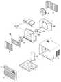
도 2는 본 발명에 따른 일체형 공기조화기 제 1 실시예의 분해 사시도,2 is an exploded perspective view of a first embodiment of an integrated air conditioner according to the present invention;
도 3은 본 발명에 따른 일체형 공기조화기 제 1 실시예의 횡단면도,3 is a cross-sectional view of a first embodiment of an integrated air conditioner according to the present invention;
도 4는 본 발명에 따른 일체형 공기조화기 제 1 실시예의 종단면도,4 is a longitudinal sectional view of the first embodiment of the integrated air conditioner according to the present invention;
도 5는 본 발명에 따른 일체형 공기조화기 제 2 실시예의 횡단면도,5 is a cross-sectional view of a second embodiment of an integrated air conditioner according to the present invention;
도 6은 도 5에 도시된 실내 송풍팬 또는 실외 송풍팬의 허브가 원추 형상일 때와 원통 형상일 때의 송풍압을 비교한 그래프,6 is a graph comparing the blowing pressure when the hub of the indoor blowing fan or the outdoor blowing fan shown in FIG. 5 has a conical shape and a cylindrical shape;
도 7은 종래 기술에 따른 일체형 공기조화기의 사시도,7 is a perspective view of an integrated air conditioner according to the prior art,
도 8은 종래 기술에 따른 일체형 공기조화기의 분해사시도,8 is an exploded perspective view of an integrated air conditioner according to the prior art,
도 9는 종래 기술에 따른 일체형 공기조화기의 종단면도이다.9 is a longitudinal sectional view of an integrated air conditioner according to the prior art.
<도면의 주요 부분에 관한 부호의 설명><Explanation of symbols on main parts of the drawings>
52: 베이스 팬53: 프레임52: base fan 53: frame
54: 우측 공기 흡입구55: 상측 공기 흡입구54: right air inlet 55: upper air inlet
56: 좌측 공기 흡입구57: 오리피스56: left air inlet 57: orifice
58: 유로 가이드59: 프론트 패널58: Euroguide 59: front panel
59a: 공기 토출구 59b: 토출 그릴59a:
62: 캐비닛63: 우측 공기 흡입구62: cabinet 63: right air intake
64: 상측 공기 흡입구65: 좌측 공기 흡입구64: upper air inlet 65: left air inlet
66: 베리어 67: 전방 회전축66: barrier 67: front axis of rotation
68: 후방 회전축70: 양축모터68: rear rotating shaft 70: biaxial motor
72: 실내 송풍팬73,73′: 허브72:
74: 블레이드76: 실외 송풍팬74: blade 76: outdoor blowing fan
77,77′: 허브78: 블레이드77,77 ′: Hub 78: Blade
80: 실내 열교환기81: 상측 열교환부80: indoor heat exchanger 81: upper heat exchanger
82: 우측 열교환부83: 좌측 열교환부82: right heat exchanger 83: left heat exchanger
86; 쉬라우드88: 오리피스86; Shroud 88: orifice
90: 실외 열교환기94: 압축기90: outdoor heat exchanger 94: compressor
96: 캐필러리 튜브96: capillary tube
본 발명은 일체형 공기조화기에 관한 것으로서, 특히 실내 공기가 상측면과 좌,우측면으로 흡입되어 열교환된 후 전방으로 토출되는 일체형 공기조화기에 관한 것이다.BACKGROUND OF THE INVENTION 1. Field of the Invention The present invention relates to an integrated air conditioner, and more particularly, to an integrated air conditioner in which indoor air is sucked into the upper side and left and right sides and heat exchanged and then discharged forward.
일반적으로 공기조화기는 실내 공기를 쾌적한 조건으로 유지할 수 있도록 흡 입공기를 처리하여 건물 또는 방에 공급하는 장치로서 크게 분리형(seperate type 또는 split type)과 일체형(window type)으로 구분된다.In general, an air conditioner is a device for treating intake air and supplying it to a building or a room to maintain indoor air in a comfortable condition. The air conditioner is classified into a separate type or a split type and a window type.
상기한 분리형과 일체형은 기능적으로는 같지만 분리형은 실내측에 냉각 장치를 설치하고 실외측에 방열 및 압축 장치를 설치하여 서로 분리된 각 장치간을 냉매 배관으로 연결시킨 것이다.The separation type and the integrated type are functionally the same, but the separation type is to install a cooling device on the indoor side and a heat dissipation and compression device on the outdoor side to connect the devices separated from each other by refrigerant piping.
한편, 일체형은 냉각, 방열의 기능을 일체화하고, 가옥의 벽이나 창에 장착하여 실내의 공기를 직접 흡입한 후 토출하거나 실외에 장착하여 실내와 연결되는 덕트를 통해 실내의 공기를 흡입한 후 토출한다.On the other hand, the integrated type integrates the functions of cooling and heat dissipation, and is mounted on a wall or window of a house to directly inhale and discharge the indoor air, or mounted on the outside to inhale the air in the room through a duct connected to the indoor and discharged. do.
도 6은 종래 기술에 따른 일체형 공기조화기의 사시도이고, 도 7은 종래 기술에 따른 일체형 공기조화기의 분해사시도이며, 도 8은 종래 기술에 따른 일체형 공기조화기의 종단면도이다.6 is a perspective view of an integrated air conditioner according to the prior art, Figure 7 is an exploded perspective view of the integrated air conditioner according to the prior art, Figure 8 is a longitudinal cross-sectional view of the integrated air conditioner according to the prior art.
종래 기술에 따른 일체형 공기조화기는 도 6 내지 도 8에 도시된 바와 같이, 베이스 팬(2)과, 상기 베이스 팬(2)의 상측에 배치되는 캐비닛(4)과, 상기 베이스 팬(2)과 캐비닛(4)의 사이를 실내측 공간(I)과 실외측 공간(O)으로 구획하는 에어 가이드(6)와, 상기 캐비닛(4)의 실내측 전면에 배치되어 일체형 공기조화기의 전면부를 구성하는 전면패널(9)과, 저온 저압의 기체 상태의 냉매를 고온 고압으로 변화시키는 압축기(12)와, 상기 실외측 공간(O)에 배치되어 상기 압축기(12)에서 나온 냉매가 실외측 공간(O) 내의 공기로 열을 방출하면서 액체 상태로 응축되는 응축기(14)와, 상기 응축기(14)에서 응축된 고온 고압의 액체 냉매를 저온 저압의 2상 냉매(액체와 기체의 혼합) 상태로 팽창시키는 팽창 밸브(미도시)와, 상기 실내 측 공간(I)에 배치되어 상기 팽창 밸브를 통과한 2상 냉매가 실내측 공간(I) 내의 공기의 열을 흡수하면서 기체 상태로 증발되는 증발기(16)를 포함한다.6 to 8, the integrated air conditioner according to the related art includes a
상기 캐비닛(4)은 실외측 측면 및 상면에 실외의 공기가 흡입되는 실외 흡입구(5)가 형성되고, 그 배면은 실외로 공기가 토출되도록 개방된다.The
상기 에어 가이드(6)는 상기 베이스 팬(2) 위에 배치된 로우어 가이드(7)와, 상기 로우어 가이드(32)의 상부에 배치되어 후술하는 터보팬(24)에 의해 강제 송풍되는 공기를 상기 실내 공기 토출구(11)로 안내하는 어퍼 가이드(8)로 구성된다.The
상기 전면 패널(9)은 실내 공기가 흡입되는 실내 공기 흡입구(10)가 전면에 형성되고, 상기 실내 공기 흡입구(10)의 상측 또는 옆에 실내측 공간(I)의 공기를 실내로 토출하는 실내 공기 토출구(11)가 형성된다.The
또한, 상기 일체형 공기조화기는 상기 에어 가이드(6)에 고정되어 실내측 공간과 실외측 공간으로 전방 샤프트(20a)와 후방 샤프트(20b)가 각각 돌출되는 양축모터(20)와, 상기 증발기(16)로 실내의 공기를 강제 순환시키도록 상기 양축모터(20)의 전방 샤프트(20a)에 연결된 터보팬(24)과, 상기 터보팬(24)의 흡입측에 위치되어 풍속을 빠르게 하는 오리피스(26)와, 상기 응축기(14)로 실외 공기를 강제 통과시키도록 상기 양축모터(20)의 후방 샤프트(20b)에 연결된 프로펠러 팬(28)과, 상기 프로펠러 팬(26)의 회전에 의해 흡입된 실외 공기의 유로를 형성하는 쉬라우드(30)를 더 포함한다.In addition, the integrated air conditioner is fixed to the
상기와 같이 구성된 종래의 일체형 공기조화기의 동작을 설명하면 다음과 같다.Referring to the operation of the conventional integrated air conditioner configured as described above are as follows.
먼저, 상기 일체형 공기조화기를 작동시키면 상기 압축기(12), 응축기(14), 팽창기구(미도시), 증발기(16)로 구성된 냉동 사이클에는 냉매가 순환되게 되고, 상기 양축 모터(20)는 구동되어 터보팬(24)과 프로펠러 팬(28)을 회전시킨다.First, when the integrated air conditioner is operated, a refrigerant is circulated in the refrigeration cycle including the
상기 일체형 공기조화기의 전방측 실내 공기는 상기 터보팬(24)의 회전에 의해 후방으로 흡입되어 상기 프론트 패널(9)의 공기 흡입구(10)를 통과하고, 상기 증발기(16)를 통하면서 저온으로 변화된 후 상기 오리피스(26)와 로우어 가이드(7)와 어퍼 가이드(8)를 차례로 통과하여 상기 유동 방향이 전방으로 꺽이며, 상기 프론트 패널(9)의 공기 토출구(11)를 통과하여 성가 일체형 공기조화기의 전방측으로 다시 토출된다.The indoor air of the front side of the integrated air conditioner is sucked backward by the rotation of the
그리고, 실외의 공기는 상기 프로펠러 팬(28)의 회전에 의해 상기 캐비닛(4)의 흡입구(5)로 흡입되어 상기 쉬라우드(30)를 통과하고 상기 응축기(14)를 통하면서 냉매의 열을 빼앗은 후 실외로 토출된다.In addition, the outdoor air is sucked into the
그러나, 종래 기술에 따른 일체형 공기조화기는 실내의 공기가 터보팬(24)의 전방에서 흡입되어 상측방향 일측으로 송풍되므로, 터보팬(24)의 부하가 커서 소비 전력이 많이 드는 문제점이 있다.However, in the integrated air conditioner according to the prior art, since indoor air is sucked from the front of the
또한, 증발기(16)와 터보팬(24)이 전후 배치되므로, 일체형 공기조화기의 전후 폭 및 전체 크기가 크게 되어 재료비 및 운송비가 증대되는 문제점이 있다.In addition, since the
본 발명은 상기한 종래 기술의 문제점을 해결하기 위하여 안출된 것으로서, 송풍팬이 부하가 작아서 소비 전력이 최소화되고 실내 공기가 3면에서 열교환되므로 냉/난방 성능이 우수한 일체형 공기조화기를 제공하는데 그 목적이 있다.The present invention has been made to solve the above-mentioned problems of the prior art, the blower fan is a small load, power consumption is minimized, and the indoor air is heat exchanged in three sides, providing an integrated air conditioner excellent in cooling / heating performance There is this.
본 발명의 다른 목적은 재료비 및 운송비를 최소화하는 것이다.
Another object of the present invention is to minimize material costs and transportation costs.
상기한 과제를 해결하기 위한 본 발명에 따른 일체형 공기조화기는 허브와, 상기 허브의 외측면을 따라 나선방향으로 길게 형성된 복수개의 블레이드로 이루어진 송풍팬과; 상기 송풍팬의 상측에 상측 열교환부가 위치되고 상기 송풍팬의 좌,우측에 좌,우측 열교환부가 위치되는 열교환기와; 상기 송풍팬의 둘레로 공기가 흡인되도록 상기 송풍팬의 앞부분을 둘러싸는 오리피스를 포함하여 구성된 것을 특징으로 한다.An integrated air conditioner according to the present invention for solving the above problems is a blower fan consisting of a hub, a plurality of blades formed in a spiral direction along the outer surface of the hub; A heat exchanger in which an upper heat exchanger is positioned above the blower fan and left and right heat exchangers are positioned in left and right sides of the blower fan; And an orifice surrounding a front portion of the blowing fan to draw air around the blowing fan.
삭제delete
또한, 상기 허브는 전면이 평평하고 내부 및 배면이 개구된 원통 형상인 것을 특징으로 한다.In addition, the hub is characterized in that the front surface is flat, and the inner and rear surfaces are cylindrical shape.
또한, 상기 허브는 전면이 평평하고 내부 및 배면이 개구된 원추 형상인 것을 특징으로 한다.In addition, the hub is characterized in that the front surface is flat, and the inner and rear surfaces are conical shape.
삭제delete
또한, 상기 복수개의 블레이드는 선단이 상기 허브보다 전방으로 더 돌출된 것을 특징으로 한다.In addition, the plurality of blades is characterized in that the front end protrudes further forward than the hub.
또한, 상기 열교환기는 상기 좌측 열교환부 및 우측 열교환부가 상기 상측 열교환부에서 라운드지게 절곡된 것을 특징으로 한다.In addition, the heat exchanger is characterized in that the left heat exchanger and the right heat exchanger is bent round in the upper heat exchanger.
삭제delete
이하, 본 발명의 실시 예를 첨부된 도면을 참조하여 상세히 설명한다.Hereinafter, embodiments of the present invention will be described in detail with reference to the accompanying drawings.
도 1은 본 발명에 따른 일체형 공기조화기 제 1 실시예의 사시도이고, 도 2는 본 발명에 따른 일체형 공기조화기 제 1 실시예의 분해 사시도이며, 도 3은 본 발명에 따른 일체형 공기조화기 제 1 실시예의 횡단면도이고, 도 4는 본 발명에 따른 일체형 공기조화기 제 1 실시예의 종단면도이다.1 is a perspective view of a first embodiment of an integrated air conditioner according to the present invention, FIG. 2 is an exploded perspective view of a first embodiment of an integrated air conditioner according to the present invention, and FIG. 3 is a first of an integrated air conditioner first embodiment according to the present invention. 4 is a longitudinal sectional view of the first embodiment of the integrated air conditioner according to the present invention.
본 실시예에 따른 일체형 공기조화기는 도 1에 도시된 바와 같이, 실내 공기(A)가 양측면과 상면으로 흡입되어 열교환된 후 전면을 통해 토출된다.As shown in FIG. 1, the integrated air conditioner according to the present exemplary embodiment, the indoor air A is sucked into both sides and the upper surface, heat exchanged, and then discharged through the front surface.
그리고, 실외 공기(B)가 양측면과 상면으로 흡입되어 열교환된 후 배면을 통해 토출된다.Then, the outdoor air (B) is sucked into both sides and the upper surface is heat exchanged and then discharged through the rear surface.
상기 일체형 공기조화기는 도 1 내지 도 4에 도시된 바와 같이, 베이스 팬(52)의 상측에 프레임(53)이 배치된다.As shown in FIGS. 1 to 4, the integrated air conditioner includes a
상기 프레임(53)은 우측면부에 우측 공기 흡입구(54)가 형성되고, 상면부에 상측 공기 흡입구(55)가 형성되며, 좌측면부에 좌측 공기 흡입구(56)가 형성되고, 실내 공기가 우측면과 상면과 좌측면의 3면를 통해 흡입되는 공기 흡입 프레임이다.The
상기 프레임(53)의 내측에는 후술하는 실내 송풍팬(72)을 둘러싸는 오리피스(57)가 형성된 에어 가이드(58)가 구비된다.Inside the
상기 오리피스(57)는 상기 실내 송풍팬(72)에 의해 송풍되는 공기의 유속을 증대시키는 것으로서, 상기 실내 송풍팬(72)의 앞부분을 외측을 둘러싸듯이 형성된다.The
상기 프레임(53)의 전면에는 프론트 패널(59)이 장착된다.The
상기 프론트 패널(59)은 상기 오리피스(57)를 통과한 공기가 상기 일체형 공기조화기의 전방으로 직진되도록 상기 오리피스(57)의 전방에 공기 토출구(59a)가 형성되고, 상기 공기 토출구(59a)의 후방을 보호하기 위한 토출 그릴(59a)이 형성된다.The
한편, 상기 일체형 공기조화기는 도 2 내지 도 4에 도시된 바와 같이, 상기 베이스 팬(52)의 후방부 상측에 캐비닛(62)이 장착된다.On the other hand, the integrated air conditioner as shown in Figures 2 to 4, the
상기 캐비닛(62)은 우측면부에 형성된 우측 공기 흡입구(63)가 형성되고, 상면부에 상측 공기 흡입구(64)가 형성되며, 좌측면부에 좌측 공기 흡입구(65)가 형성되고, 배면이 개방되어, 우측면과 상면과 좌측면를 통해 공기가 흡입되고 배면을 통해 공기가 토출된다.The
한편, 상기 베이스 팬(52)의 중앙부 상면에는 상기 일체형 공기조화기의 내부를 실내측 공간(I)과 실외측 공간(O)으로 구획하는 베리어(66)가 장착된다.On the other hand, on the upper surface of the central portion of the
상기 베리어(66)에는 상기 베리어(66)의 전방을 향해 전방 회전축(67)이 돌출되고 상기 베리어(66)의 후방을 향해 후방 회전축(68)이 돌출되는 양축모터(70) 가 장착된다.The
상기 양축모터(70)는 실내 송풍팬(72)과 실외 송풍팬(76)을 함께 회전시키는 일종의 송풍모터로서, 상기 양축 모터(70)의 전방 회전축(67)에는 상기 프레임(53)의 공기 흡입구(54,55,56)로 공기를 흡입하여 상기 공기 토출구(59a)로 토출하도록 실내 송풍팬(72)이 상기 프레임(53) 내측에 위치되게 연결되고, 상기 양축 모터(70)의 후방 회전축(68)에는 상기 캐비닛(62)의 공기 흡입구(63,64,65)로 공기를 흡입하여 상기 캐비닛(62)의 배면으로 토출하도록 실외 송풍팬(76)이 상기 캐비닛(62)의 내측에 위치되게 연결된다.The two-
상기 실내 송풍팬(72)은 후방 또는 둘레의 공기를 흡인하여 전방으로 송풍하는 것으로서, 상기 양축 모터(70)의 전방 회전축(67)에 고정된 허브(73)와, 상기 허브(73)의 외둘레를 따라 나선 방향으로 길게 형성된 복수개의 블레이드(74,75)로 구성되고, 카이팬 또는 엑스팬이라 칭한다.The
상기 허브(73)는 전면이 평평하고 내부 및 배면이 개구된 원통 형상이고, 전면 중앙에는 상기 전방 회전축이 삽입되어 고정되는 고정 리브(73a)가 형성된다.The
삭제delete
상기 복수개의 블레이드(74,75)는 선단(74a,75a)이 상기 허브(73)보다 전방으로 더 돌출된다.The plurality of
상기 실외 송풍팬(76)은 전방 또는 둘레의 공기를 흡인하여 후방으로 송풍하는 것으로서, 상기 양축 모터(70)의 후방 회전축(68)에 고정된 허브(77)와, 상기 허브(77)의 외둘레를 따라 나선 방향으로 길게 형성된 복수개의 블레이드(78,79)로 구성되고, 카이팬 또는 엑스팬이라 칭한다.The outdoor blower fan (76) sucks air in the front or circumference and blows it backwards, and the hub (77) fixed to the rear rotation shaft (68) of the double shaft motor (70) and the outside of the hub (77). Consists of a plurality of
상기 허브(77)는 배면이 평평하고 내부 및 배면이 개구된 원통 형상이고, 전면 중앙에는 상기 후방 회전축(68)이 삽입되어 고정되는 고정 리브(77a)가 형성된다.The
상기 복수개의 블레이드(78,79)는 전단에서 후단으로 갈수록 상향 경사지는 제 1 블레이드(78)와, 전단에서 후단으로 갈수록 하향 경사지는 제 2 블레이드(79)로 구성된다.The plurality of blades (78, 79) is composed of a
그리고, 상기 프레임(53)과 실내 송풍팬(72)의 사이에는 상기 실내 송풍팬(72)에 의해 흡입된 공기가 열교환되는 실내 열교환기(80)가 배치된다.In addition, an
상기 실내 열교환기(80)는 역 ‘U’자 모양으로 좌우가 벤딩되어, 상기 송풍팬의 상측에 상측 열교환부(81)가 위치되고 상기 송풍팬의 좌,우측에 좌, 우측 열교환부(82,83)가 위치된다.The
즉, 상기 실내 열교환기(80)는 상기 상측 공기 흡입구(55)의 하측에 좌우로 배치된 상측 열교환부(81)와, 상기 우측 공기 흡입구(54)의 좌측에 상하로 배치된 우측 열교환부(82)와, 상기 좌측 공기 흡입구(56)의 우측에 상하로 길게 배치된 좌측 열교환부(83)로 구성된다.That is, the
상기 실내 열교환기(80)는 상기 우측 열교환부(82) 및 좌측 열교환부(83)가 상기 상측 열교환부(81)에서 라운드지게 절곡된다.In the
한편, 상기 캐비닛(62)의 내측에는 상기 실외 송풍팬(76)에 의해 흡입된 실외 공기의 유로를 형성하는 쉬라우드(86)가 배치된다.Meanwhile, a
상기 쉬라우드(86)에는 상기 실외 송풍팬(76)이 내측에 위치되는 오리피스(88)가 형성된다.The
상기 쉬라우드(86)의 내측 또는 후방에는 상기 실외 송풍팬(76)에 의해 후방으로 송풍되는 공기로 냉매의 열을 방출하는 실외 열교환기(90)가 배치된다.An
상기 실외 열교환기(90)는 좌우로 길게 배치된 직육면체 형상을 갖는다.The
참조 부호 94는 상기 실외측 공간(O)에 위치되도록 상기 베이스 팬(52)에 장착된 압축기이다.
참조 부호 96은 상기 실외 열교환기(90)에서 응축된 냉매가 팽창된 후 상기 실내 열교화기(80)로 이동될 수 있도록 상기 실외 열교환기(90)와 실내 열교환기(80) 사이에 배치된 팽창기구인 캐필러리 튜브이다.
상기와 같이 구성된 본 발명의 동작을 살펴보면 다음과 같다.Looking at the operation of the present invention configured as described above are as follows.
먼저, 상기 일체형 공기조화기를 작동시키면, 상기 압축기(94)는 구동되어 고온 고압의 기체 냉매를 토출하고, 토출된 고온 고압의 기체 냉매는 실외 열교환기(90)를 통과하면서 주변으로 열을 방출하면서 응축되며, 응축된 냉매는 상기 캐필러리 튜브(96)를 통과하면서 감압되어 2상 냉매로 변하고, 감압된 냉매는 상기 실내 열교환기(80)를 통과하면서 주변의 열을 빼앗아 증발되며, 상기 압축기(94)로 순환된다.First, when the integrated air conditioner is operated, the
한편, 상기 일체형 공기조화기는 상기 압축기(94)의 구동시 상기 양축 모터(70)를 구동시킨다.On the other hand, the integrated air conditioner drives the
상기 양축 모터(70)가 구동되면, 상기 실내 송풍팬(72)은 회전되어 둘레 또는 후방에 부압을 발생시키고, 상기 프레임(56)의 옆과 상측의 공기(A)는 상기 프레임(53)의 우측 공기 흡입구(54)와 상측 공기 흡입구(55)와 좌측 공기 흡입구(56)를 통과하여 상기 일체형 공기조화기의 내측 전방인 실내측 공간(I)으로 흡입된다.When the two-
상기 우측 공기 흡입구(54)와 상측 공기 흡입구(55)와 좌측 공기 흡입구(56)의 각각을 통해 흡입된 공기는 상기 실내 열교환기(80)의 상측 열교환부(81)와 우측 열교환부(82)와 좌측 열교환부(83)의 각각을 통과하면서 냉매로 열을 빼앗겨 냉각되고, 상기 실내 송풍팬(72)으로 흡인된다.The air sucked through each of the right
상기 실내 송풍팬(72)으로 흡입된 공기는 상기 허브(73)의 외주면과 상기 제 1,2 블레이드(74,75)에 안내되어 회오리 바람을 일으키면서 전방으로 확산되고, 상기 제 1,2 블레이드(74,75)의 선단의 안내를 받으면서 직진성이 확보되어 전방으로 송풍된다.The air sucked into the
전방으로 송풍된 공기는 상기 오리피스(57)를 통과하면서 유속이 빨라지고, 상기 프론트 패널(59)의 공기 토출구(59a)를 차례로 통과하여 상기 일체형 공기조화기의 전방으로 토출된다.The air blown forward passes through the
한편, 상기 양축 모터(70)의 구동시 상기 실외 송풍팬(76)은 회전되어 둘레 또는 전방에 부압을 발생시키고, 상기 캐비닛(62)의 옆과 상측의 공기(B)는 상기 캐비닛(62)의 우측 공기 흡입구(63)와 상측 공기 흡입구(64)와 좌측 공기 흡입구(65)를 통과하여 상기 일체형 공기조화기의 내측 중 후방인 실외측 공간(O)으로 흡입된다.On the other hand, the
상기 우측 공기 흡입구(63)와 상측 공기 흡입구(64)와 좌측 공기 흡입구(65)의 각각을 통과한 공기는 상기 실외 송풍팬(76)으로 흡인된다.Air passing through each of the
상기 실외 송풍팬(76)으로 흡입된 공기는 상기 허브(77)의 외주면과 상기 제 1,2 블레이드(78,79)에 안내되어 회오리 바람을 일으키면서 후방으로 확산되고, 상기 제 1,2 블레이드(78,79)의 후단의 안내를 받으면서 직진성이 확보되어 후방으로 송풍된다.The air sucked into the
후방으로 송풍된 공기는 상기 쉬라우드(86)의 오리피스(88)를 통과한 후 상기 실외 열교환기(90)를 통과하면서 냉매의 열을 빼앗아 가열되며, 상기 캐비닛(62)의 배면을 통해 상기 일체형 공기조화기의 후방으로 토출된다.The air blown to the rear passes through the
도 5는 본 발명에 따른 일체형 공기조화기 제 2 실시예의 횡단면도이다.5 is a cross-sectional view of a second embodiment of an integrated air conditioner according to the present invention.
본 실시예에 따른 일체형 공기조화기는 도 5에 도시된 바와 같이, 실내 송풍팬(72)의 허브(73′)가 전면이 평평하고 내부 및 배면이 개구된 원추 형상으로 이루어지고, 실외 송풍팬(76)의 허브(77′)가 배면이 평평하고 내부 및 전면이 개구된 원추 형상으로 이루어지며, 상기 허브(73′,77′) 이외의 기타 구성 및 작용은 본 발명 제 1 실시예와 동일하므로 동일부호를 사용하고 그 상세한 설명은 생략한다.As shown in FIG. 5, the integrated air conditioner according to the present embodiment has a
도 6은 도 5에 도시된 실내 송풍팬 또는 실외 송풍팬의 허브가 원추 형상일 때와 원통 형상일 때의 송풍압을 비교한 그래프이다.FIG. 6 is a graph comparing the blowing pressure when the hub of the indoor blowing fan or the outdoor blowing fan shown in FIG. 5 has a cone shape and a cylinder shape.
도 6에 도시된 바와 같이, 실내 송풍팬(72) 또는 실외 송풍팬(76)의 허브(73,77)가 원통 형상일 때(점선)에는 송풍압(P)이 풍량(Q)에 따라 급격히 감소한 후 점차 감소되므로 바람의 세기의 편차가 심한 반면에, 실내 송풍팬(72) 또는 실외 송풍팬(76)의 허브(73′,77′)가 원추 형상일 때(실선)에는 송풍압(P)이 풍량(Q)에 따라 고르게 감소하므로, 바람의 세기의 편차가 작게 된다.As shown in FIG. 6, when the
한편, 본 발명은 상기의 실시예에 한정되지 않고, 상기 프레임(53)과 캐비닛(62)이 일체로 형성되는 것도 가능함은 물론이다.On the other hand, the present invention is not limited to the above embodiment, of course, the
상기와 같이 구성되는 본 발명에 따른 일체형 공기조화기는 송풍팬이 둘레 또는 후방의 공기를 흡인하여 전방으로 송풍하므로, 송풍팬의 공기 흡입 면적이 넓어, 다량의 공기가 신속하게 흡입될 수 있고 송풍팬의 부하 및 소비 전력이 최소화되는 이점이 있다.In the integrated air conditioner according to the present invention configured as described above, since the blowing fan sucks air in the circumference or the rear and blows it forward, the air suction area of the blowing fan is wide, and a large amount of air can be sucked quickly and the blowing fan Has the advantage of minimizing the load and power consumption.
또한, 본 발명에 따른 일체형 공기조화기는 열교환기가 송풍팬의 상측과 좌측과 우측에 위치되어, 실내 공기와 열교환기의 열전달면적이 크기 때문에, 실내 공기를 보다 신속하게 냉방/난방시킬 수 있고, 일체형 공기조화기의 전후 폭 및 전체 크기를 최소화하는 이점이 있다.In addition, the integrated air conditioner according to the present invention, since the heat exchanger is located on the upper side, the left side and the right side of the blower fan, and the heat transfer area of the indoor air and the heat exchanger is large, it is possible to cool / heat the indoor air more quickly. There is an advantage of minimizing the front and rear width and overall size of the air conditioner.
또한, 상기 송풍팬은 송풍모터의 회전축이 연결된 허브와, 상기 허브의 외측 면을 따라 나선방향으로 형성된 복수개의 블레이드로 구성되어, 후방 뿐만 아니라 측방의 공기도 흡인하여 송풍할 수 있는 이점이 있다.In addition, the blower fan is composed of a hub connected to the rotation axis of the blower motor, and a plurality of blades formed in a spiral direction along the outer surface of the hub, there is an advantage that can suck and blow not only the rear but also the side air.
또한, 상기 복수개의 블레이드는 후단에서 전단으로 갈수록 상향 경사지는 제 1 블레이드와, 후단에서 전단으로 갈수록 하향 경사지는 제 2 블레이드로 구성되어, 공기가 회오리 바람을 일으키며 전방으로 확산 토출할 수 있는 이점이 있다.In addition, the plurality of blades is composed of a first blade that is inclined upward from the rear end to the front end, and a second blade that is inclined downward from the rear end to the front end, which has the advantage that the air can be diffused and discharged in front of the whirlwind have.
또한, 상기 복수개의 블레이드는 상기 허브보다 전방으로 더 돌출되어, 상기 블레이드를 안내하는 공기의 직진성을 확보하므로, 전방으로 송풍되는 공기의 난류 발생 및 그에 따른 소음을 최소화하하는 이점이 있다.In addition, the plurality of blades protrude further forward than the hub, thereby ensuring the straightness of the air guiding the blade, there is an advantage of minimizing the generation of turbulence of the air blown forward and the resulting noise.
또한, 본 발명에 따른 일체형 공기조화기는 상기 송풍팬의 앞부분을 둘러싸는 오리피스를 더 포함하여 구성되어, 전방으로 송풍되는 공기를 보다 빠르게 토출할 수 있는 이점이 있다.In addition, the integrated air conditioner according to the present invention further comprises an orifice surrounding the front portion of the blowing fan, there is an advantage that can be discharged to the front air blowing faster.
Claims (8)
Translated fromKoreanPriority Applications (3)
| Application Number | Priority Date | Filing Date | Title |
|---|---|---|---|
| KR1020040043637AKR100579571B1 (en) | 2004-06-14 | 2004-06-14 | Integrated Air Conditioner |
| US11/150,242US7386989B2 (en) | 2004-06-14 | 2005-06-13 | Air conditioner |
| CNB2005100878534ACN100565023C (en) | 2004-06-14 | 2005-06-14 | Air-conditioner |
Applications Claiming Priority (1)
| Application Number | Priority Date | Filing Date | Title |
|---|---|---|---|
| KR1020040043637AKR100579571B1 (en) | 2004-06-14 | 2004-06-14 | Integrated Air Conditioner |
Publications (2)
| Publication Number | Publication Date |
|---|---|
| KR20050118506A KR20050118506A (en) | 2005-12-19 |
| KR100579571B1true KR100579571B1 (en) | 2006-05-15 |
Family
ID=35459083
Family Applications (1)
| Application Number | Title | Priority Date | Filing Date |
|---|---|---|---|
| KR1020040043637AExpired - Fee RelatedKR100579571B1 (en) | 2004-06-14 | 2004-06-14 | Integrated Air Conditioner |
Country Status (3)
| Country | Link |
|---|---|
| US (1) | US7386989B2 (en) |
| KR (1) | KR100579571B1 (en) |
| CN (1) | CN100565023C (en) |
Families Citing this family (46)
| Publication number | Priority date | Publication date | Assignee | Title |
|---|---|---|---|---|
| CA2580325A1 (en)* | 2006-03-02 | 2007-09-02 | Fabricant De Poeles International Inc. | Solid fuel burning stove |
| BRPI0722037A2 (en)* | 2007-09-18 | 2014-03-25 | Carrier Corp | AIR CONDITIONING UNIT. |
| CN103759339B (en)* | 2013-12-17 | 2016-01-20 | 宁波瑞易电器科技发展有限公司 | The air-conditioning of convenient cleaning |
| CN105020878A (en)* | 2014-04-17 | 2015-11-04 | 广东美的集团芜湖制冷设备有限公司 | Multi-row heat exchanger and air conditioner |
| CN105135541A (en)* | 2015-08-21 | 2015-12-09 | 国网上海市电力公司 | Heat exchange method suitable for capacitor and electric reactor chambers |
| EP3460368B1 (en)* | 2016-07-08 | 2020-08-05 | PHC Holdings Corporation | Heat insulation box manufacturing method and heat insulation box |
| US11624326B2 (en) | 2017-05-21 | 2023-04-11 | Bj Energy Solutions, Llc | Methods and systems for supplying fuel to gas turbine engines |
| US11560845B2 (en) | 2019-05-15 | 2023-01-24 | Bj Energy Solutions, Llc | Mobile gas turbine inlet air conditioning system and associated methods |
| US11105518B2 (en)* | 2019-06-12 | 2021-08-31 | Haier Us Appliance Solutions, Inc. | Wall sleeve assembly for a packaged terminal air conditioner unit |
| CA3092829C (en) | 2019-09-13 | 2023-08-15 | Bj Energy Solutions, Llc | Methods and systems for supplying fuel to gas turbine engines |
| US12338772B2 (en) | 2019-09-13 | 2025-06-24 | Bj Energy Solutions, Llc | Systems, assemblies, and methods to enhance intake air flow to a gas turbine engine of a hydraulic fracturing unit |
| CA3092863C (en) | 2019-09-13 | 2023-07-18 | Bj Energy Solutions, Llc | Fuel, communications, and power connection systems and related methods |
| US12065968B2 (en) | 2019-09-13 | 2024-08-20 | BJ Energy Solutions, Inc. | Systems and methods for hydraulic fracturing |
| CA3092865C (en) | 2019-09-13 | 2023-07-04 | Bj Energy Solutions, Llc | Power sources and transmission networks for auxiliary equipment onboard hydraulic fracturing units and associated methods |
| US10815764B1 (en) | 2019-09-13 | 2020-10-27 | Bj Energy Solutions, Llc | Methods and systems for operating a fleet of pumps |
| US11002189B2 (en) | 2019-09-13 | 2021-05-11 | Bj Energy Solutions, Llc | Mobile gas turbine inlet air conditioning system and associated methods |
| US11604113B2 (en) | 2019-09-13 | 2023-03-14 | Bj Energy Solutions, Llc | Fuel, communications, and power connection systems and related methods |
| CA3197583A1 (en) | 2019-09-13 | 2021-03-13 | Bj Energy Solutions, Llc | Fuel, communications, and power connection systems and related methods |
| US10895202B1 (en) | 2019-09-13 | 2021-01-19 | Bj Energy Solutions, Llc | Direct drive unit removal system and associated methods |
| US10961914B1 (en) | 2019-09-13 | 2021-03-30 | BJ Energy Solutions, LLC Houston | Turbine engine exhaust duct system and methods for noise dampening and attenuation |
| US11015594B2 (en) | 2019-09-13 | 2021-05-25 | Bj Energy Solutions, Llc | Systems and method for use of single mass flywheel alongside torsional vibration damper assembly for single acting reciprocating pump |
| US11708829B2 (en) | 2020-05-12 | 2023-07-25 | Bj Energy Solutions, Llc | Cover for fluid systems and related methods |
| US10968837B1 (en) | 2020-05-14 | 2021-04-06 | Bj Energy Solutions, Llc | Systems and methods utilizing turbine compressor discharge for hydrostatic manifold purge |
| US11428165B2 (en) | 2020-05-15 | 2022-08-30 | Bj Energy Solutions, Llc | Onboard heater of auxiliary systems using exhaust gases and associated methods |
| US11208880B2 (en) | 2020-05-28 | 2021-12-28 | Bj Energy Solutions, Llc | Bi-fuel reciprocating engine to power direct drive turbine fracturing pumps onboard auxiliary systems and related methods |
| US11109508B1 (en) | 2020-06-05 | 2021-08-31 | Bj Energy Solutions, Llc | Enclosure assembly for enhanced cooling of direct drive unit and related methods |
| US11208953B1 (en) | 2020-06-05 | 2021-12-28 | Bj Energy Solutions, Llc | Systems and methods to enhance intake air flow to a gas turbine engine of a hydraulic fracturing unit |
| US11111768B1 (en) | 2020-06-09 | 2021-09-07 | Bj Energy Solutions, Llc | Drive equipment and methods for mobile fracturing transportation platforms |
| US10954770B1 (en) | 2020-06-09 | 2021-03-23 | Bj Energy Solutions, Llc | Systems and methods for exchanging fracturing components of a hydraulic fracturing unit |
| US11066915B1 (en) | 2020-06-09 | 2021-07-20 | Bj Energy Solutions, Llc | Methods for detection and mitigation of well screen out |
| US11125066B1 (en) | 2020-06-22 | 2021-09-21 | Bj Energy Solutions, Llc | Systems and methods to operate a dual-shaft gas turbine engine for hydraulic fracturing |
| US11028677B1 (en) | 2020-06-22 | 2021-06-08 | Bj Energy Solutions, Llc | Stage profiles for operations of hydraulic systems and associated methods |
| US11933153B2 (en) | 2020-06-22 | 2024-03-19 | Bj Energy Solutions, Llc | Systems and methods to operate hydraulic fracturing units using automatic flow rate and/or pressure control |
| US11939853B2 (en) | 2020-06-22 | 2024-03-26 | Bj Energy Solutions, Llc | Systems and methods providing a configurable staged rate increase function to operate hydraulic fracturing units |
| US11473413B2 (en) | 2020-06-23 | 2022-10-18 | Bj Energy Solutions, Llc | Systems and methods to autonomously operate hydraulic fracturing units |
| US11466680B2 (en) | 2020-06-23 | 2022-10-11 | Bj Energy Solutions, Llc | Systems and methods of utilization of a hydraulic fracturing unit profile to operate hydraulic fracturing units |
| US11149533B1 (en) | 2020-06-24 | 2021-10-19 | Bj Energy Solutions, Llc | Systems to monitor, detect, and/or intervene relative to cavitation and pulsation events during a hydraulic fracturing operation |
| US11220895B1 (en) | 2020-06-24 | 2022-01-11 | Bj Energy Solutions, Llc | Automated diagnostics of electronic instrumentation in a system for fracturing a well and associated methods |
| US11193360B1 (en) | 2020-07-17 | 2021-12-07 | Bj Energy Solutions, Llc | Methods, systems, and devices to enhance fracturing fluid delivery to subsurface formations during high-pressure fracturing operations |
| CN111854135A (en)* | 2020-08-24 | 2020-10-30 | 广东海悟科技有限公司 | A middle frame structure of a cabinet air conditioner |
| US11946701B2 (en)* | 2020-11-11 | 2024-04-02 | B/E Aerospace, Inc. | Heat transfer systems |
| US11639654B2 (en) | 2021-05-24 | 2023-05-02 | Bj Energy Solutions, Llc | Hydraulic fracturing pumps to enhance flow of fracturing fluid into wellheads and related methods |
| CA3180024A1 (en) | 2021-10-25 | 2023-04-25 | Bj Energy Solutions, Llc | Systems and methods to reduce acoustic resonance or disrupt standing wave formation in a fluid manifold of a high-pressure fracturing system |
| USD1066619S1 (en)* | 2021-11-19 | 2025-03-11 | Lg Electronics Inc. | Window air conditioner |
| WO2023130122A1 (en)* | 2022-01-03 | 2023-07-06 | Johnson Controls Tyco IP Holdings LLP | Integrated hvac system with variable refrigerant flow unit and air handling unit |
| CN115540041A (en)* | 2022-08-10 | 2022-12-30 | 青岛海尔空调器有限总公司 | A saddle type window air conditioner |
Family Cites Families (8)
| Publication number | Priority date | Publication date | Assignee | Title |
|---|---|---|---|---|
| US2486828A (en)* | 1949-11-01 | Air conditioning apparatus for | ||
| US3943728A (en)* | 1974-01-02 | 1976-03-16 | Borg-Warner Corporation | Air-cooled condenser apparatus |
| US4641502A (en)* | 1985-01-09 | 1987-02-10 | The Duo-Therm Corporation | Roof mount air conditioner |
| KR960007043B1 (en)* | 1987-04-30 | 1996-05-27 | 가부시기가이샤 히다찌 세이사꾸쇼 | Air Conditioning Device for Railway Vehicles |
| US4802342A (en)* | 1988-04-18 | 1989-02-07 | Thermo King Corporation | Protective grille and air flow straightener for transport refrigeration apparatus |
| JPH04272499A (en)* | 1991-02-27 | 1992-09-29 | Matsushita Electric Ind Co Ltd | Blower and manufacture of its impeller |
| US5950446A (en) | 1998-10-01 | 1999-09-14 | Whirlpool Corporation | Compact air conditioner |
| CN1276186C (en) | 2002-04-19 | 2006-09-20 | 松下电器产业株式会社 | Draft fan impeller for air conditioner |
- 2004
- 2004-06-14KRKR1020040043637Apatent/KR100579571B1/ennot_activeExpired - Fee Related
- 2005
- 2005-06-13USUS11/150,242patent/US7386989B2/ennot_activeExpired - Fee Related
- 2005-06-14CNCNB2005100878534Apatent/CN100565023C/ennot_activeExpired - Fee Related
Also Published As
| Publication number | Publication date |
|---|---|
| CN100565023C (en) | 2009-12-02 |
| US7386989B2 (en) | 2008-06-17 |
| US20050274134A1 (en) | 2005-12-15 |
| CN1715792A (en) | 2006-01-04 |
| KR20050118506A (en) | 2005-12-19 |
Similar Documents
| Publication | Publication Date | Title |
|---|---|---|
| KR100579571B1 (en) | Integrated Air Conditioner | |
| CN111615607B (en) | Air conditioner | |
| KR100550571B1 (en) | Integrated Air Conditioner | |
| KR100613512B1 (en) | Integrated Air Conditioner | |
| KR20050118948A (en) | Window type air conditioner | |
| KR20060005196A (en) | Integrated Air Conditioner | |
| KR100579572B1 (en) | Air conditioner | |
| KR100579570B1 (en) | Integrated Air Conditioner | |
| KR100504485B1 (en) | Air-Conditioner | |
| KR100471438B1 (en) | The condenser's cooling system of an air-conditioner | |
| US7930897B2 (en) | Window type air conditioner | |
| KR100613513B1 (en) | Integrated Air Conditioner | |
| KR20110083913A (en) | Refrigerator | |
| CN100541025C (en) | window air conditioner | |
| KR200156408Y1 (en) | Indoor unit of separating type airconditioner | |
| KR100789817B1 (en) | Centrifugal Fans for Air Conditioners | |
| KR20140147326A (en) | Fan assembly and air conditioner having the same | |
| KR20030063876A (en) | air conditioner | |
| WO2005040686A2 (en) | Window type air conditioner | |
| KR20050118947A (en) | Window type air conditioner | |
| JP2002267319A (en) | refrigerator | |
| KR100443930B1 (en) | Indoor unit of air conditioner for air-flow innovating structure | |
| KR0122718Y1 (en) | Discharge device of outdoor unit for air conditioner | |
| KR20060017012A (en) | Air conditioner | |
| KR20060004839A (en) | Integrated Air Conditioner |
Legal Events
| Date | Code | Title | Description |
|---|---|---|---|
| A201 | Request for examination | ||
| PA0109 | Patent application | St.27 status event code:A-0-1-A10-A12-nap-PA0109 | |
| PA0201 | Request for examination | St.27 status event code:A-1-2-D10-D11-exm-PA0201 | |
| P11-X000 | Amendment of application requested | St.27 status event code:A-2-2-P10-P11-nap-X000 | |
| P13-X000 | Application amended | St.27 status event code:A-2-2-P10-P13-nap-X000 | |
| R15-X000 | Change to inventor requested | St.27 status event code:A-3-3-R10-R15-oth-X000 | |
| R16-X000 | Change to inventor recorded | St.27 status event code:A-3-3-R10-R16-oth-X000 | |
| D13-X000 | Search requested | St.27 status event code:A-1-2-D10-D13-srh-X000 | |
| D14-X000 | Search report completed | St.27 status event code:A-1-2-D10-D14-srh-X000 | |
| E902 | Notification of reason for refusal | ||
| PE0902 | Notice of grounds for rejection | St.27 status event code:A-1-2-D10-D21-exm-PE0902 | |
| PG1501 | Laying open of application | St.27 status event code:A-1-1-Q10-Q12-nap-PG1501 | |
| E13-X000 | Pre-grant limitation requested | St.27 status event code:A-2-3-E10-E13-lim-X000 | |
| P11-X000 | Amendment of application requested | St.27 status event code:A-2-2-P10-P11-nap-X000 | |
| P13-X000 | Application amended | St.27 status event code:A-2-2-P10-P13-nap-X000 | |
| E701 | Decision to grant or registration of patent right | ||
| PE0701 | Decision of registration | St.27 status event code:A-1-2-D10-D22-exm-PE0701 | |
| GRNT | Written decision to grant | ||
| PR0701 | Registration of establishment | St.27 status event code:A-2-4-F10-F11-exm-PR0701 | |
| PR1002 | Payment of registration fee | St.27 status event code:A-2-2-U10-U11-oth-PR1002 Fee payment year number:1 | |
| PG1601 | Publication of registration | St.27 status event code:A-4-4-Q10-Q13-nap-PG1601 | |
| PN2301 | Change of applicant | St.27 status event code:A-5-5-R10-R13-asn-PN2301 St.27 status event code:A-5-5-R10-R11-asn-PN2301 | |
| PR1001 | Payment of annual fee | St.27 status event code:A-4-4-U10-U11-oth-PR1001 Fee payment year number:4 | |
| R18-X000 | Changes to party contact information recorded | St.27 status event code:A-5-5-R10-R18-oth-X000 | |
| R18-X000 | Changes to party contact information recorded | St.27 status event code:A-5-5-R10-R18-oth-X000 | |
| PR1001 | Payment of annual fee | St.27 status event code:A-4-4-U10-U11-oth-PR1001 Fee payment year number:5 | |
| PR1001 | Payment of annual fee | St.27 status event code:A-4-4-U10-U11-oth-PR1001 Fee payment year number:6 | |
| PR1001 | Payment of annual fee | St.27 status event code:A-4-4-U10-U11-oth-PR1001 Fee payment year number:7 | |
| FPAY | Annual fee payment | Payment date:20130424 Year of fee payment:8 | |
| PR1001 | Payment of annual fee | St.27 status event code:A-4-4-U10-U11-oth-PR1001 Fee payment year number:8 | |
| FPAY | Annual fee payment | Payment date:20140424 Year of fee payment:9 | |
| PR1001 | Payment of annual fee | St.27 status event code:A-4-4-U10-U11-oth-PR1001 Fee payment year number:9 | |
| LAPS | Lapse due to unpaid annual fee | ||
| PC1903 | Unpaid annual fee | St.27 status event code:A-4-4-U10-U13-oth-PC1903 Not in force date:20150509 Payment event data comment text:Termination Category : DEFAULT_OF_REGISTRATION_FEE | |
| PN2301 | Change of applicant | St.27 status event code:A-5-5-R10-R13-asn-PN2301 St.27 status event code:A-5-5-R10-R11-asn-PN2301 | |
| PC1903 | Unpaid annual fee | St.27 status event code:N-4-6-H10-H13-oth-PC1903 Ip right cessation event data comment text:Termination Category : DEFAULT_OF_REGISTRATION_FEE Not in force date:20150509 | |
| PN2301 | Change of applicant | St.27 status event code:A-5-5-R10-R13-asn-PN2301 St.27 status event code:A-5-5-R10-R11-asn-PN2301 | |
| P22-X000 | Classification modified | St.27 status event code:A-4-4-P10-P22-nap-X000 |