KR100579406B1 - Vertically Moved Organic Material Deposition Equipment - Google Patents
Vertically Moved Organic Material Deposition EquipmentDownload PDFInfo
- Publication number
- KR100579406B1 KR100579406B1KR1020040067259AKR20040067259AKR100579406B1KR 100579406 B1KR100579406 B1KR 100579406B1KR 1020040067259 AKR1020040067259 AKR 1020040067259AKR 20040067259 AKR20040067259 AKR 20040067259AKR 100579406 B1KR100579406 B1KR 100579406B1
- Authority
- KR
- South Korea
- Prior art keywords
- organic material
- organic
- deposition
- substrate
- deposition source
- Prior art date
- Legal status (The legal status is an assumption and is not a legal conclusion. Google has not performed a legal analysis and makes no representation as to the accuracy of the status listed.)
- Expired - Fee Related
Links
Images


Classifications
- C—CHEMISTRY; METALLURGY
- C23—COATING METALLIC MATERIAL; COATING MATERIAL WITH METALLIC MATERIAL; CHEMICAL SURFACE TREATMENT; DIFFUSION TREATMENT OF METALLIC MATERIAL; COATING BY VACUUM EVAPORATION, BY SPUTTERING, BY ION IMPLANTATION OR BY CHEMICAL VAPOUR DEPOSITION, IN GENERAL; INHIBITING CORROSION OF METALLIC MATERIAL OR INCRUSTATION IN GENERAL
- C23C—COATING METALLIC MATERIAL; COATING MATERIAL WITH METALLIC MATERIAL; SURFACE TREATMENT OF METALLIC MATERIAL BY DIFFUSION INTO THE SURFACE, BY CHEMICAL CONVERSION OR SUBSTITUTION; COATING BY VACUUM EVAPORATION, BY SPUTTERING, BY ION IMPLANTATION OR BY CHEMICAL VAPOUR DEPOSITION, IN GENERAL
- C23C14/00—Coating by vacuum evaporation, by sputtering or by ion implantation of the coating forming material
- C23C14/06—Coating by vacuum evaporation, by sputtering or by ion implantation of the coating forming material characterised by the coating material
- C23C14/12—Organic material
- C—CHEMISTRY; METALLURGY
- C23—COATING METALLIC MATERIAL; COATING MATERIAL WITH METALLIC MATERIAL; CHEMICAL SURFACE TREATMENT; DIFFUSION TREATMENT OF METALLIC MATERIAL; COATING BY VACUUM EVAPORATION, BY SPUTTERING, BY ION IMPLANTATION OR BY CHEMICAL VAPOUR DEPOSITION, IN GENERAL; INHIBITING CORROSION OF METALLIC MATERIAL OR INCRUSTATION IN GENERAL
- C23C—COATING METALLIC MATERIAL; COATING MATERIAL WITH METALLIC MATERIAL; SURFACE TREATMENT OF METALLIC MATERIAL BY DIFFUSION INTO THE SURFACE, BY CHEMICAL CONVERSION OR SUBSTITUTION; COATING BY VACUUM EVAPORATION, BY SPUTTERING, BY ION IMPLANTATION OR BY CHEMICAL VAPOUR DEPOSITION, IN GENERAL
- C23C14/00—Coating by vacuum evaporation, by sputtering or by ion implantation of the coating forming material
- C23C14/04—Coating on selected surface areas, e.g. using masks
- C23C14/042—Coating on selected surface areas, e.g. using masks using masks
- C—CHEMISTRY; METALLURGY
- C23—COATING METALLIC MATERIAL; COATING MATERIAL WITH METALLIC MATERIAL; CHEMICAL SURFACE TREATMENT; DIFFUSION TREATMENT OF METALLIC MATERIAL; COATING BY VACUUM EVAPORATION, BY SPUTTERING, BY ION IMPLANTATION OR BY CHEMICAL VAPOUR DEPOSITION, IN GENERAL; INHIBITING CORROSION OF METALLIC MATERIAL OR INCRUSTATION IN GENERAL
- C23C—COATING METALLIC MATERIAL; COATING MATERIAL WITH METALLIC MATERIAL; SURFACE TREATMENT OF METALLIC MATERIAL BY DIFFUSION INTO THE SURFACE, BY CHEMICAL CONVERSION OR SUBSTITUTION; COATING BY VACUUM EVAPORATION, BY SPUTTERING, BY ION IMPLANTATION OR BY CHEMICAL VAPOUR DEPOSITION, IN GENERAL
- C23C14/00—Coating by vacuum evaporation, by sputtering or by ion implantation of the coating forming material
- C23C14/22—Coating by vacuum evaporation, by sputtering or by ion implantation of the coating forming material characterised by the process of coating
- C23C14/225—Oblique incidence of vaporised material on substrate
- C—CHEMISTRY; METALLURGY
- C23—COATING METALLIC MATERIAL; COATING MATERIAL WITH METALLIC MATERIAL; CHEMICAL SURFACE TREATMENT; DIFFUSION TREATMENT OF METALLIC MATERIAL; COATING BY VACUUM EVAPORATION, BY SPUTTERING, BY ION IMPLANTATION OR BY CHEMICAL VAPOUR DEPOSITION, IN GENERAL; INHIBITING CORROSION OF METALLIC MATERIAL OR INCRUSTATION IN GENERAL
- C23C—COATING METALLIC MATERIAL; COATING MATERIAL WITH METALLIC MATERIAL; SURFACE TREATMENT OF METALLIC MATERIAL BY DIFFUSION INTO THE SURFACE, BY CHEMICAL CONVERSION OR SUBSTITUTION; COATING BY VACUUM EVAPORATION, BY SPUTTERING, BY ION IMPLANTATION OR BY CHEMICAL VAPOUR DEPOSITION, IN GENERAL
- C23C14/00—Coating by vacuum evaporation, by sputtering or by ion implantation of the coating forming material
- C23C14/22—Coating by vacuum evaporation, by sputtering or by ion implantation of the coating forming material characterised by the process of coating
- C23C14/24—Vacuum evaporation
- C23C14/243—Crucibles for source material
- C—CHEMISTRY; METALLURGY
- C23—COATING METALLIC MATERIAL; COATING MATERIAL WITH METALLIC MATERIAL; CHEMICAL SURFACE TREATMENT; DIFFUSION TREATMENT OF METALLIC MATERIAL; COATING BY VACUUM EVAPORATION, BY SPUTTERING, BY ION IMPLANTATION OR BY CHEMICAL VAPOUR DEPOSITION, IN GENERAL; INHIBITING CORROSION OF METALLIC MATERIAL OR INCRUSTATION IN GENERAL
- C23C—COATING METALLIC MATERIAL; COATING MATERIAL WITH METALLIC MATERIAL; SURFACE TREATMENT OF METALLIC MATERIAL BY DIFFUSION INTO THE SURFACE, BY CHEMICAL CONVERSION OR SUBSTITUTION; COATING BY VACUUM EVAPORATION, BY SPUTTERING, BY ION IMPLANTATION OR BY CHEMICAL VAPOUR DEPOSITION, IN GENERAL
- C23C14/00—Coating by vacuum evaporation, by sputtering or by ion implantation of the coating forming material
- C23C14/22—Coating by vacuum evaporation, by sputtering or by ion implantation of the coating forming material characterised by the process of coating
- C23C14/24—Vacuum evaporation
- C23C14/26—Vacuum evaporation by resistance or inductive heating of the source
- H—ELECTRICITY
- H10—SEMICONDUCTOR DEVICES; ELECTRIC SOLID-STATE DEVICES NOT OTHERWISE PROVIDED FOR
- H10K—ORGANIC ELECTRIC SOLID-STATE DEVICES
- H10K71/00—Manufacture or treatment specially adapted for the organic devices covered by this subclass
- H—ELECTRICITY
- H10—SEMICONDUCTOR DEVICES; ELECTRIC SOLID-STATE DEVICES NOT OTHERWISE PROVIDED FOR
- H10K—ORGANIC ELECTRIC SOLID-STATE DEVICES
- H10K71/00—Manufacture or treatment specially adapted for the organic devices covered by this subclass
- H10K71/10—Deposition of organic active material
- H10K71/16—Deposition of organic active material using physical vapour deposition [PVD], e.g. vacuum deposition or sputtering
- H10K71/164—Deposition of organic active material using physical vapour deposition [PVD], e.g. vacuum deposition or sputtering using vacuum deposition
Landscapes
- Chemical & Material Sciences (AREA)
- Engineering & Computer Science (AREA)
- Chemical Kinetics & Catalysis (AREA)
- Materials Engineering (AREA)
- Mechanical Engineering (AREA)
- Metallurgy (AREA)
- Organic Chemistry (AREA)
- Manufacturing & Machinery (AREA)
- Physical Vapour Deposition (AREA)
Abstract
Translated fromKoreanDescription
Translated fromKorean도 1a는 본 발명의 일 실시예에 따른 수직 이동형 유기물 증착 장치를 설명하기 위한 개략도.Figure 1a is a schematic diagram for explaining a vertically movable organic material deposition apparatus according to an embodiment of the present invention.
도 1b는 본 발명의 일 실시예에 따른 수직 이동형 유기물 증착 장치의 유기물 증착원을 설명하기 위한 사시도.1B is a perspective view illustrating an organic material deposition source of a vertically movable organic material deposition apparatus according to an embodiment of the present invention.
도 2는 본 발명의 일 실시예에 따른 수직 이동형 유기물 증착 장치의 유기물 증착원을 설명하기 위한 평면도.2 is a plan view illustrating an organic material deposition source of a vertically movable organic material deposition apparatus according to an embodiment of the present invention.
도 3은 본 발명의 다른 실시예에 따른 수직 이동형 유기물 증착 장치를 설명하기 위한 개략도.Figure 3 is a schematic diagram for explaining a vertically movable organic material deposition apparatus according to another embodiment of the present invention.
(도면의 주요 부위에 대한 부호의 설명)(Explanation of symbols for main parts of drawing)
100; 수직 이동형 유기물 증착 장치100; Vertically Moved Organic Material Deposition Equipment
200; 챔버300, 500, 600; 유기물 증착원200; Chambers 300, 500, 600; Organic material deposition source
310; 유기물 저장부320; 유기물 유도로310; Organic
330; 가열 히터 340; 내부 열 반사판330;
350; 외부 냉각판 360; 유기물 분사 노즐350; External
370; 측정 장치 400; 이동 기구370;
S; 기판M; 마스크 패턴S; Substrate M; Mask pattern
본 발명은 유기 반도체 소자 등의 유기 박막 형성을 위한 수직 이동형 유기물 증착 장치에 관한 것으로, 더욱 상세하게는 기판을 대략 수직으로 세운 상태에서 유기물을 증착하여 유기 박막을 형성하여 대형 기판에 적용 가능하고 균일한 두께의 유기 박막을 형성할 수 있으며, 유기물 저장부와 유기물 분사 노즐을 분리하여 기판 및 마스크 패턴의 변형을 최소화한 수직 이동형 유기물 증착 장치에 관한 것이다.The present invention relates to a vertically movable organic material deposition apparatus for forming an organic thin film, such as an organic semiconductor device, and more particularly, to form an organic thin film by depositing an organic material in a state in which the substrate is substantially vertical, and is applicable to a large substrate. The present invention relates to a vertically movable organic material deposition apparatus capable of forming an organic thin film having a thickness and minimizing deformation of a substrate and a mask pattern by separating an organic material storage unit and an organic material spray nozzle.
일반적으로, 유기 전계 발광 소자(OLED, Organic light Emitting Device) 등을 포함하는 유기 반도체 소자의 유기 박막은 크게, 저분자 유기 물질을 진공 중에서 증발시켜 유기 박막을 형성하는 방법과, 고분자 유기 물질을 용제에 용해한 후, 스핀 코팅(spin coating), 딥 코팅(dip coating), 닥터 블레이팅, 잉크젯 프린팅 등을 이용하여 유기 박막을 형성하는 방법이 있다.In general, an organic thin film of an organic semiconductor device including an organic light emitting device (OLED) or the like is largely a method of forming an organic thin film by evaporating a low molecular organic material in a vacuum and a polymer organic material in a solvent. After dissolution, there is a method of forming an organic thin film using spin coating, dip coating, doctor blading, inkjet printing, or the like.
상기한 방법 중에서, 진공에서 저분자 유기 물질로 이루어지는 박막을 제작하는 경우에는 형성하고자 하는 형상의 개구부를 가지는 쉐도우 마스크 패턴(shadow mask pattern)을 기판의 앞에 정렬하여, 상기 기판에 유기 물질을 증착함으로써, 상기 기판 상에 유기 박막을 제작하게 된다.In the above-described method, when fabricating a thin film made of a low molecular organic material in a vacuum, a shadow mask pattern having an opening having a shape to be formed is aligned in front of a substrate, and the organic material is deposited on the substrate. An organic thin film is prepared on the substrate.
상기한 바와 같은 저분자 유기 물질로 이루어지는 유기 박막의 제조 방법으 로는 점형 유기물 증착원을 이용하는 방법과, 선형 유기물 증착원을 이용하는 방법 등이 있다.As a method of manufacturing an organic thin film made of a low molecular organic material as described above, there is a method using a point organic material deposition source, a method using a linear organic material deposition source and the like.
그러나, 상기한 바와 같은 점형 또는 선형의 유기물 증착원을 이용하여 대형 기판 상에 유기 박막을 형성하는 경우에는, 상기 기판과 증발원 사이의 거리가 함께 증가하게 되며, 상기 기판과 증발원 사이의 거리의 증가는 상기 기판 상에 형성되는 유기 박막의 균일성이 저하되는 원인이 된다.However, in the case of forming an organic thin film on a large substrate using a point- or linear organic material deposition source as described above, the distance between the substrate and the evaporation source is increased together, and the distance between the substrate and the evaporation source is increased. This causes a decrease in the uniformity of the organic thin film formed on the substrate.
또한, 상기 기판과 증발원 사이의 거리가 증가하게 되면, 상기 증발원에서 증발된 유기물이 상기 기판 이외의 진공 챔버에 증착되어 유기물의 손실이 증가하게 되며, 상기 유기물이 고가인 것을 감안하면, 제조 단가가 증가하는 문제점이 있다.In addition, when the distance between the substrate and the evaporation source is increased, the organic material evaporated from the evaporation source is deposited in a vacuum chamber other than the substrate, so that the loss of the organic material is increased, considering that the organic material is expensive, There is an increasing problem.
또한, 유기 박막의 균일성 확보를 위하여 상기 쉐도우 마스크 패턴과 증발원이 소정의 각도를 이루도록 하여 유기 박막을 형성할 수 있다. 이때, 상기 쉐도우 마스크 패턴과 증발원이 소정의 각도를 이루는 경우, 상기 쉐도우 마스크 패턴에 의한 그림자 효과가 발생하여 원하는 형상의 유기 박막을 얻기 어려운 문제점이 있다.In addition, in order to ensure uniformity of the organic thin film, the shadow mask pattern and the evaporation source may be formed at a predetermined angle to form an organic thin film. In this case, when the shadow mask pattern and the evaporation source form a predetermined angle, there is a problem in that a shadow effect caused by the shadow mask pattern is generated and it is difficult to obtain an organic thin film having a desired shape.
또한, 증발원과 분사 노즐이 일체화되어 있어, 열에 의한 기판 및 마스크 패턴의 열에 의한 변형이 발생할 수 있는 문제점이 있다.In addition, since the evaporation source and the spray nozzle are integrated, there is a problem that deformation due to heat of the substrate and the mask pattern due to heat may occur.
또한, 대형 기판의 경우 기판의 쳐짐 현상으로 인하여, 기판의 중앙부와 에지부의 박막의 균일성이 다른 문제점이 있다.In addition, in the case of a large substrate, there is a problem that the uniformity of the thin film of the center portion and the edge portion of the substrate is different due to the drooping phenomenon of the substrate.
또한, 종래의 유기물 증착 장치는 유기물의 균일한 증착을 위하여 기판이 이 동하는 방식을 채택하는데, 이러한 기판이 이동하는 경우 챔버의 크기가 매우 커지는 문제점이 있다.In addition, the conventional organic material deposition apparatus adopts a method of moving the substrate for uniform deposition of the organic material, there is a problem that the size of the chamber is very large when such a substrate is moved.
본 발명의 목적은 상기한 종래 기술의 문제점을 해결하기 위한 것으로, 본 발명은 기판을 대략 수직으로 세운 상태에서 유기물을 증착하여 유기 박막을 형성하여 대형 기판에 적용 가능하고 균일한 두께의 유기 박막을 형성할 수 있으며, 유기물 저장부와 유기물 분사 노즐을 분리하여 기판 및 마스크 패턴의 변형을 최소화한 수직 이동형 유기물 증착 장치를 제공하는 데에 그 목적이 있다.An object of the present invention is to solve the above problems of the prior art, the present invention is to form an organic thin film by depositing an organic material in a state in which the substrate is upright approximately to form an organic thin film of uniform thickness and applicable to large substrate An object of the present invention is to provide a vertically movable organic material deposition apparatus capable of forming and separating the organic material storage unit and the organic material spray nozzle to minimize deformation of the substrate and the mask pattern.
상기한 목적을 달성하기 위한 본 발명은 몸체를 이루며, 기판을 지면에 70° 내지 110°의 각도를 유지하도록 하는 챔버와; 유기물 저장부, 유기물 유도로, 가열 히터, 내부 열 반사판, 외부 냉각판 및 유기물 분사 노즐부로 이루어지며, 상기 기판 상에 유기물을 증착하여 유기 박막을 형성하기 위한 유기물 증착원과; 상기 유기물 증착원을 수직 방향으로 이동시킬 수 있는 유기물 증착원 이동 기구를 구비하는 수직 이동형 유기물 증착 장치를 제공하는 것을 특징으로 한다.The present invention for achieving the above object comprises a chamber to form a body, the substrate to maintain an angle of 70 ° to 110 ° to the ground; An organic material storage source, an organic material induction furnace, a heating heater, an internal heat reflection plate, an external cooling plate, and an organic material spray nozzle unit, and an organic material deposition source for forming an organic thin film by depositing an organic material on the substrate; It is characterized by providing a vertically movable organic material deposition apparatus having an organic material deposition source moving mechanism capable of moving the organic material deposition source in the vertical direction.
상기 유기물 저장부는 다수의 셀로 구분되는 것이 바람직하다.The organic material storage unit is preferably divided into a plurality of cells.
상기 유기물 유도로는 상기 유기물 저장부에서 증발된 유기물 입자의 이동 경로인 것이 바람직하다.The organic induction furnace is preferably a movement path of the organic particles evaporated from the organic storage unit.
상기 유기물 유도로는 유기물 입자의 최종 이동 방향을 지면에 -20° 내지 20°의 각도를 유지하도록 하는 것이 바람직하다.The organic induction furnace is preferably to maintain the final moving direction of the organic particles to the ground angle of -20 ° to 20 °.
상기 가열 히터는 유기물 저장부 및 유기물 유도로 외부에 설치되어 상기 유기물 저장부 및 유기물 유도로를 가열하는 것이 바람직하다.The heating heater is preferably installed outside the organic material storage unit and the organic material induction furnace to heat the organic material storage unit and the organic material induction furnace.
상기 내부 열 반사판은 상기 가열 히터보다 외부에 설치되는 것이 바람직하다.The internal heat reflecting plate is preferably installed outside the heating heater.
상기 외부 냉각판은 상기 내부 열 반사판의 외부에 위치하여, 상기 유기물 증발부 내부의 열이 외부로 전도되는 것을 방지하는 것이 바람직하며, 상기 외부 냉각판은 냉매를 이용하여 외부 열 반사판을 냉각시키는 것이 바람직하다.The external cooling plate is located outside of the internal heat reflecting plate to prevent the heat inside the organic material evaporation unit from being conducted to the outside. The external cooling plate cools the external heat reflecting plate using a refrigerant. desirable.
상기 유기물 증착원은 상기 유기물 분사 노즐부의 유기물 분사 방향의 선단에 위치하여 상기 기판 상에 증착되는 유기물의 증착률 및 증착 두께를 측정하는 측정 센서를 더 구비하는 것이 바람직하다.The organic material deposition source may further include a measurement sensor which is located at the tip of the organic material spray nozzle unit in the organic material spray direction to measure the deposition rate and the deposition thickness of the organic material deposited on the substrate.
상기 유기물에 불순물을 도핑하기 위한 수단을 더 구비할 수도 있다.The organic material may further include means for doping impurities.
또한, 본 발명은 몸체를 이루며, 기판을 지면에 70° 내지 110°의 각도를 유지하도록 하는 챔버와; 상기 기판 상에 물질을 증착하여 박막을 형성하며, 증착 물질 저장부, 증착 물질 유도로, 상기 증착 물질 저장부 및 증착 물질 유도로를 가열하는 가열 히터, 상기 증착 물질 저장부 및 증착 물질 유도로의 외부에 형성되어 열을 반사시켜주기 위한 내부 열 반사판, 상기 내부 열반사판 외부에 설치되어 상기 내부열 반사판을 냉각시켜 주는 외부 냉각판, 증착 물질 분사 노즐부로 이루어지는 다수의 증착원과; 상기 증착원을 수직 방향으로 이동시킬 수 있는 유기물 증착원 이동 기구를 구비하는 수직 이동형 유기물 증착 장치를 제공하는 것을 특징으로 한다.In addition, the present invention comprises a chamber to form a body, the substrate to maintain an angle of 70 ° to 110 ° to the ground; Depositing a material on the substrate to form a thin film, a heating heater for heating the deposition material storage unit, the deposition material induction furnace, the deposition material storage unit and the deposition material induction furnace, the deposition material storage unit and the deposition material induction furnace A plurality of deposition sources including an internal heat reflecting plate formed outside and reflecting heat, an external cooling plate installed outside the internal heat reflecting plate to cool the internal heat reflecting plate, and a deposition material spray nozzle unit; It is characterized by providing a vertically movable organic material deposition apparatus having an organic material deposition source moving mechanism capable of moving the deposition source in the vertical direction.
상기 다수의 증착원은 서로 동일한 유기물을 내포하여, 기판, 특히 대형 기판 상에 균일한 유기 박막을 형성할 수 있다.The plurality of deposition sources may contain the same organic material to form a uniform organic thin film on a substrate, particularly a large substrate.
또한, 상기 다수의 증착원은 제 1 증착원 및 제 2 증착원으로 이루어지는 것이 바람직하며, 더욱 바람직하게는 상기 제 1 증착원은 기판 상의 박막의 원재료 증착원이며, 상기 제 2 증착원은 상기 박막의 특성 개선을 위한 불순물을 상기 박막에 포함시키기 위한 불순물 증착원인 것이 바람직하다.In addition, the plurality of deposition sources are preferably composed of a first deposition source and a second deposition source, more preferably the first deposition source is a raw material deposition source of a thin film on a substrate, the second deposition source is the thin film The impurity deposition source for including the impurity for improving the characteristics of the thin film is preferable.
상기 다수의 서로 다른 증착원은 분사 각도가 조절 가능한 것이 바람직하다.Preferably, the plurality of different deposition sources have an adjustable injection angle.
이하 첨부된 도면을 참조하여, 본 발명의 실시예를 설명한다.Hereinafter, embodiments of the present invention will be described with reference to the accompanying drawings.
본 발명의 실시예에 따른 수직 이동형 유기물 증착 장치는 기판을 대략 수직으로 세운 상태에서 유기물을 증착하여 유기 박막을 형성하여 대형 기판에 적용 가능하고 균일한 두께의 유기 박막을 형성할 수 있으며, 유기물 저장부와 유기물 분사 노즐을 분리하여 기판 및 마스크 패턴의 변형을 최소화할 수 있다.In the vertically movable organic material deposition apparatus according to an embodiment of the present invention, by depositing the organic material in a state in which the substrate is substantially vertical, the organic thin film may be formed to form an organic thin film, and may be formed on an organic thin film having a uniform thickness. Deformation of the substrate and the mask pattern may be minimized by separating the portion and the organic spray nozzle.
도 1a는 본 발명의 일 실시예에 따른 수직 이동형 유기물 증착 장치를 설명하기 위한 개략도이다. 도 1b는 본 발명의 일 실시예에 따른 수직 이동형 유기물 증착 장치의 유기물 증착원을 설명하기 위한 사시도이다.1A is a schematic diagram illustrating a vertically moving organic material deposition apparatus according to an embodiment of the present invention. 1B is a perspective view illustrating an organic material deposition source of a vertically movable organic material deposition apparatus according to an embodiment of the present invention.
도 1a 및 도 1b를 참조하면, 본 발명의 실시예에 따른 수직 이동형 유기물 증착 장치(100)는 상기 수직 이동형 유기물 증착 장치(100)의 몸체를 이루는 챔버(200)와, 기판(S) 상으로 유기물 입자를 분사시키기 위한 유기물 증착원(300)과, 상기 유기물 층착원(300)을 수직 방향으로 이동시킬 수 있는 유기물 증착원 이동 기구(400)를 구비하는 구조로 이루어진다.1A and 1B, a vertically movable organic
상기 챔버(200)는 유기물을 증착하고자 하는 기판(S)을 대략 수직, 바람직하게는 지면과 70° 내지 110°의 각도를 유지하도록 한다. 또한, 상기 챔버(200)는 진공 챔버인 것이 바람직하다.The
상기 유기물 증착원(300)은 유기물 저장부(310), 유기물 유도로(320), 가열 히터(330), 내부 열 반사판(340), 외부 냉각판(350), 유기물 분사 노즐부(360) 및 측정 장치(370)로 이루어진다.The organic
상기 유기물 저장부(310)는 상기 기판(S) 상에 형성되는 유기 박막의 원재료인 유기물을 저장하는 부분으로써, 적어도 하나의 셀로 구분되어 지는 도가니로 이루어지는 것이 바람직하다.The
상기 유기물 유도로(320)는 상기 유기물 저장부(310)에서 증발된 유기물 입자를 상기 유기물 분사 노즐부(360)로 이송하는 역할을 수행하며, 상기 유기물 입자의 이동 경로를 결정하는 역할을 수행한다. 보다 상세히 설명하면, 상기 유기물 저장부(310)에서 상기 유기물 입자가 상향으로 증발되며, 상기 대략 수직으로 세워진 기판(S) 상에 유기물을 증착하기 위해서는 상기 유기물 입자의 최종 이동 경로가 대략 수평 방향이어야 하므로, 상기 유기물 유도로(320)의 말단은 지면과 -20° 내지 20°의 각도를 유지하여야 한다. 즉, 상기 유기물 입자의 최종 이동 경로를 지면과 -20° 내지 20°의 각도를 유지하도록 유도한다. 또한, 상기 유기물 유도로(320)의 중간 부분은 소정 각도로 경사지도록 형성하여, 상기 유기물 저장부(310)에서 증발되는 유기물 중 일부 클러스터(cluster) 형태의 유기물이 유도로 내벽과 충돌하여 유기물 입자 상태로 부서지도록 함으로써, 상기 클러스터 형태의 유기물 이 자연스럽게 상기 유기물 유도로(320) 내부에서 고르게 혼합되며, 상기 기판(S) 상에 유기물이 뭉쳐서 증착되는 것을 방지하는 역할을 수행한다.The
상기 가열 히터(330)는 상기 유기물 저장부(310) 및 유기물 유도로(320) 외부에 설치되어 상기 유기물 저장부(310) 및 유기물 유도로(320)를 가열하는 역할을 수행한다. 즉, 상기 유기물 저장부(310)를 가열하여, 상기 유기물이 유기물의 입자 상태로 증발시키며, 증발된 유기물 입자를 상기 유기물 유도로(320) 내부에서 응축되지 않도록 가열하는 것이다.The
상기 내부 열 반사판(340)은 상기 가열 히터(330)보다 외부에 설치되어 상기 유기물 증착원(300)의 열 효율을 증가시키기 위한 것으로, 상기 유기물 증착원(300) 내부의 열용량을 흡수할 수 있도록 다단으로 구성되어 있다.The internal
상기 외부 냉각판(350)은 상기 내부 열 반사판(340)의 외부에 위치하여, 상기 유기물 증착원(300) 내부의 열이 외부로 전도되는 것을 방지한다. 상기 외부 냉각판(350)은 냉매를 이용하여 내부 열 반사판(340)을 냉각시킨다.The
상기 유기물 분사 노즐부(360)는 상기 유기물 저장부(310)에서 증발되어 상기 유기물 유도로(320)를 통하여 유입되는 유기물 입자를 대략 수직으로 세원진 기판(S) 상으로 분사하며, 상기 유기물 입자가 상기 기판(S) 상에 증착, 분포되는 형태를 결정하는 역할을 수행한다. 또한, 상기 유기물 분사 노즐부(360)는 유기물 입자를 분사시에 분사 각도가 조절 가능한 형태로 이루어지는 것이 바람직하다. 상기 유기물 분사 노즐부(360)의 개구된 형태에 따라 유기물 입자가 분사되는 형태가 조절 가능하므로, 상기 유기물 저장부(310) 내의 유기물의 균일한 증발이 가능하도록 제어할 수 있다.The organic
상기 측정 장치(370)는 지면에 70° 내지 110°의 각으로 세워진 기판(S) 상에 증착되는 유기물의 증착률 및 두께를 측정하는 역할을 수행한다. 또한, 상기 측정 장치(370)는 상기 유기물 분사 노즐부(360)의 유기물 분사 방향의 선단부에 위치하며, 상기 유기물 분사 노즐부(360)와 일체화되어 있다.The measuring
상기 유기물 증착원 이동 기구(400)는 상기 유기물 증착원(300)을 수직 방향으로 이동시키기 위한 장치이다. 이때, 상기 유기물 증착원 이동 기구(400)는 진공으로 유지되는 상기 챔버(200) 내에서 사용이 적합한 수직 이동 기구로써, 상기 유기물 증착원(300) 중 적어도 상기 유기물 분사 노즐(360)의 이동 속도를 조절할 수 있도록 이송 속도 조절 기구(도면 상에는 미도시)를 더 구비할 수 있다.The organic material deposition
도면의 참조 부호 M은 상기 기판(S) 상에 증착되는 유기물의 형상을 결정하는 마스크 패턴이다.Reference numeral M in the figure is a mask pattern for determining the shape of the organic material deposited on the substrate S.
상기한 바와 같은 수직 이동형 유기물 증착 장치(100)를 이용하는 유기 박막의 형성 방법은 하기와 같다.A method of forming an organic thin film using the vertically movable organic
우선, 상기 수직 이동형 유기물 증착 장치(100)의 챔버 내에 기판(S)을 지면에 대략 수직, 바람직하게는 지면과 70° 내지 110의 각도를 유지하도록 장착한다.First, the substrate S is mounted in the chamber of the vertically movable organic
그런 다음, 상기 유기물 증착원(300)의 유기물을 수용하고 있는 상기 유기물 저장부(310)를 상기 가열 히터(330)를 통하여 가열한다.Then, the organic
이때, 상기 가열 히터(330)를 통하여 상기 유기물 저장부(310) 도가니 내의 각 셀에 수용되어 있는 유기물이 유기물 입자 상태로 증발하게 된다.At this time, the organic matter contained in each cell in the crucible of the organic
상기 증발된 유기물 입자는 상기 유기물 유도로(320)를 통하여 상기 유기물 분사 노즐부(360)로 유입된다. 이때, 상기 유기물 입자의 이동 경로는 상기 유기물 유도로(320)의 형상에 의하여 결정된다. 상기 유기물 유도로(320)의 말단이 지면과 -20° 내지 20°의 각도를 유지하므로, 상기 유기물 증착원(300) 내에서의 상기 유기물 입자의 최종 이동 경로는 지면과 -20° 내지 20°의 각도를 유지한다. 또한, 상기 유기물 유도로(320)는 상기 유기물 저장부(310)에서 증발되는 유기물 중 완전히 입자 상태로 증발되지 않고, 다수의 유기물 입자가 뭉친 클러스터 형태를 유지하는 유기물이 상기 유기물 유도로(320)의 내벽과 충돌하여 유기물 입자 상태로 부서지도록 함으로써, 상기 기판(S) 상으로 분사되는 유기물 입자의 크기를 균일하게 한다. 또한, 상기 유기물 유도로(320) 외부의 가열 히터(330)는 상기 유기물 유도로(320) 내에서 상기 증발된 유기물 입자가 응축되지 않도록 한다.The evaporated organic particles are introduced into the organic
상기 유기물 분사 노즐부(360)로 유입된 유기물 입자는 상기 유기물 분사 노즐부(360)를 통하여 상기 기판(S) 상으로 증착되어 유기 박막을 형성한다. 이때, 상기 유기물 증착원 이동 기구(400)를 통하여 상기 유기물 증착원(300)이 수직 방향으로 이동하며, 상기 지면과 70° 내지 110의 각도를 유지하는 기판(S) 상에 유기물 입자가 증착되어 유기 박막을 형성한다. 또한, 상기 유기물 입자는 그 최종 이동 경로가 지면과 -20° 내지 20°의 각도를 유지하므로, 상기 유기물 입자가 상기 유기물 분사 노즐부(360)을 통하여 상기 기판(S)으로 분사될 때, 상기 유기물 입자는 지면과 -20° 내지 20°의 각도로 분사된다. 또한, 상기 유기물 입자가 상기 기판(S) 상으로 증착시에 상기 유기물 분사 노즐부(360)의 개구된 형태에 따라 상기 기판(S) 상에 증착되는 유기물 입자의 형태가 조절된다.The organic particles introduced into the organic
한편, 상기 유기물 분사 노즐부(360)의 유기물 분사 방향으로 선단부에 설치되어 있는 상기 측정 장치(370)는 상기 유기물을 상기 기판(S) 상에 증착하는 동안, 상기 기판(S) 상에 증착되는 유기물의 증착률 및 유기물의 증착 두께를 측정한다. 따라서, 상기 측정 장치(370)를 이용하여, 유기 박막을 형성하는 동안 유기물 입자의 증착률 및 유기물 증착 두께를 제어함으로써, 균일한 유기 박막의 두께의 재현성을 실현할 수 있다.On the other hand, the measuring
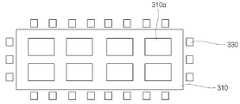
한편, 도 2는 본 발명의 일 실시예에 따른 수직 이동형 유기물 증착 장치의 유기물 증착원을 설명하기 위한 평면도로써, 유기물 저장부 및 상기 유기물 저장부 주변의 가열 히터에 한정하여 도시한 것이다.On the other hand, Figure 2 is a plan view for explaining the organic material deposition source of the vertically movable organic material deposition apparatus according to an embodiment of the present invention, it is shown to be limited to the organic storage unit and the heating heater around the organic storage unit.
도 2를 참조하면, 유기물 저장부(310)는 적어도 하나의 셀(310a)로 구분되며, 각각의 셀(310a)에 유기물을 저장하게 된다. 또한, 가열 히터(330)는 상기 유기물 저장부(310) 주변에 고르게 분포한다.Referring to FIG. 2, the organic
이것은 유기물 저장부(310)의 상기 유기물을 증발시키는 경우, 상기 유기물 저장부(310)가 하나의 셀로 이루어지면, 상기 유기물 저장부(310) 내부의 온도 분포 차이로 인하여 위치에 따른 유기물 증발률의 차이가 발생하게 된다. 이러한 위치에 따른 증발률의 차이는 균일한 불순물의 주입 및 유기 박막의 균일성을 저하하게 되는데, 상기 유기물 저장부(310)를 다수의 셀(310a)로 구분함으로써, 상기 유기물 저장부(310) 내의 유기물 증발률을 균일하게 할 수 있다.When the organic matter evaporation of the organic
한편, 도 3은 본 발명의 다른 실시예에 따른 수직 이동형 유기물 증착 장치 를 설명하기 위한 개략도이다.On the other hand, Figure 3 is a schematic diagram for explaining a vertically movable organic material deposition apparatus according to another embodiment of the present invention.
도 3을 참조하면, 본 발명의 다른 실시예에 따른 유기물 증착 장치는 도 1에 도시된 바와 같은 유기물 증착원을 다수개 구비하며, 상기 각 유기물 증착원을 수직으로 이동시키기 위한 유기물 증착원 이동 기구를 구비하는 구조로 이루어진다.Referring to FIG. 3, the organic material deposition apparatus according to another embodiment of the present invention includes a plurality of organic material deposition sources as shown in FIG. 1, and an organic material deposition source moving mechanism for vertically moving each organic material deposition source. It is made of a structure having a.
일 예로, 상기 서로 다른 다수의 증착원은 제 1 유기물 증착원(500) 및 제 2 유기물 증착원(600)으로 이루어지며, 상기 제 1 유기물 증착원(500) 및 제 2 유기물 증착원(600)은 동일한 유기물을 내포하고, 서로 소정 간격 이격되어, 이동하며, 균일한 유기 박막을 기판 상에 증착할 수 있다. 특히, 대형 기판을 적용하여 유기 박막을 증착하는 경우에 보다 유리하다.For example, the plurality of different deposition sources include a first organic
또는, 상기 서로 다른 다수의 유기물 증착원은 제 1 유기물 증착원(500) 및 제 2 유기물 증착원(600)으로 이루어지며, 상기 제 1 유기물 증착원(500) 및 제 2 유기물 증착원(600) 중 어느 하나의 유기물 증착원 예를 들면, 제 1 유기물 증착원(500)은 유기 박막의 원재료인 유기물을 상기 기판(S) 상으로 분사하는 유기물 증착원이며, 제 2 유기물 증착원(600)은 상기 유기 박막의 특성 개선을 위한 불순물을 상기 유기 박막에 포함시키기 위한 유기물 증착원이다.Alternatively, the plurality of different organic material deposition sources includes a first organic
이때, 상기 제 1 유기물 증착원(500) 및 제 2 유기물 증착원(600)은 유기 박막에 유기물을 포함시키기 위하여, 상기 기판(S) 상에 물질을 증착시키기 전에 일정한 영역 내에서 혼합이 되도록 분사 각도의 조절이 가능하다.
가령, 제1 유기물 증착원(500)의 유기물 유도로가 되는 노즐 끝단의 방향을 지면과 평행한 수평선과 θ1 각도를 이루도록 함으로써 노즐에서 분사되는 유기물 입자는 지면과 θ1 의 각도를 이루게 된다. 같은 방식으로 제2 유기물 증착원(600)의 노즐 끝단의 방향을 지면과 평행한 수평선과 θ2각도를 이루도록 함으로써 노즐에서 분사되는 유기물 입자는 지면과 θ2의 각도를 이루게 된다.In this case, the first organic
For example, the direction of the end of the nozzle, which is the organic induction path of the first organic
또한, 상기 제 1 유기물 증착원(500) 및 제 2 유기물 증착원(600) 분사 노즐의 분사 방향 선단에 각각 유기물의 증착률 및 증착 두께를 측정할 수 있는 측정 장치를 설치함으로써, 상기 기판(S) 상에 불순물을 포함하는 유기 박막을 형성하는 동안 증착률 및 유기물의 두께 제어를 가능하게 하며, 유기 박막에 포함되는 불순물 함량의 제어를 가능하게 한다.In addition, the substrate (S) by providing a measuring device for measuring the deposition rate and the deposition thickness of the organic material at the tip of the injection direction of the first organic
상기한 바와 같이, 본 발명의 실시예에 따른 유기물 증착 장치(100)는 상기 기판(S)을 지면과 대략 수직인 θ3각도로 세운 상태에서 유기물 입자를 분사하여 유기 박막을 형성함으로써, 대형 기판의 경우 기판의 쳐짐 형상을 방지하므로, 대형 기판에 적용이 가능하다.As described above, the organic
또한, 상기 유기물 저장부(310)와 유기물 분사 노즐부(360)를 분리하여, 상기 기판(S) 및 마스크 패턴(M)의 열에 의한 변형을 방지하며, 상기 기판(S) 상에 유기물의 입자 분포가 균일한 유기 박막을 형성할 수 있다.In addition, by separating the
또한, 상기 내부 열 반사판(340) 및 외부 냉각판(350)을 통하여 상기 유기물 분사 노즐부(360)를 제외한 외부로 열이 방출되는 것을 방지함으로써, 상기 기판(S) 및 마스크 패턴(M)에 미치는 열 영향을 최소화할 수 있다. 즉, 열에 의한 상기 기판(S) 및 마스크 패턴(M)의 변형을 방지할 수 있다.In addition, heat is prevented from being released to the substrate S and the mask pattern M through the internal
또한, 다수의 서로 다른 유기물 증착원을 이용하는 경우에는 상기 유기 박막의 특성을 개선하기 위한 불순물의 주입이 가능하다.In addition, when using a plurality of different organic material deposition sources it is possible to inject impurities to improve the characteristics of the organic thin film.
또한, 상기 유기물 증착원 이동 기구(400)를 통하여 상기 유기물 증착원(300, 500, 600)이 이동하며 상기 기판(S) 상에 유기물을 증착하므로, 종래의 유기물 증착원 이동 기구가 없이, 기판을 이동시키는 유기물 증착 장치를 이용하여 유기물을 증착하는 경우에 비하여, 챔버의 크기를 약 75% 이내로 축소하는 것이 가능 하다.In addition, since the organic material deposition source (300, 500, 600) is moved through the organic material deposition
상기한 바와 같이 본 발명에 따르면, 본 발명은 기판을 대략 수직으로 세운 상태에서 유기물을 증착하여 유기 박막을 형성하여 대형 기판에 적용 가능하고 균일한 두께의 유기 박막을 형성할 수 있으며, 유기물 저장부와 유기물 분사 노즐을 분리하여 기판 및 마스크 패턴의 변형을 최소화한 수직 이동형 유기물 증착 장치를 제공할 수 있다.As described above, according to the present invention, the present invention is applicable to a large substrate by forming an organic thin film by depositing an organic material in a state in which the substrate is erected vertically, and forming an organic thin film having a uniform thickness. It is possible to provide a vertically movable organic material deposition apparatus which minimizes the deformation of the substrate and the mask pattern by separating the organic spray nozzles.
상기에서는 본 발명의 바람직한 실시예를 참조하여 설명하였지만, 해당 기술 분야의 숙련된 당업자는 하기의 특허 청구 범위에 기재된 본 발명의 사상 및 영역으로부터 벗어나지 않는 범위 내에서 본 발명을 다양하게 수정 및 변경시킬 수 있음을 이해할 수 있을 것이다.While the foregoing has been described with reference to preferred embodiments of the present invention, those skilled in the art will be able to variously modify and change the present invention without departing from the spirit and scope of the invention as set forth in the claims below. It will be appreciated.
Claims (16)
Translated fromKoreanPriority Applications (3)
| Application Number | Priority Date | Filing Date | Title |
|---|---|---|---|
| KR1020040067259AKR100579406B1 (en) | 2004-08-25 | 2004-08-25 | Vertically Moved Organic Material Deposition Equipment |
| JP2005239881AJP4516499B2 (en) | 2004-08-25 | 2005-08-22 | Organic vapor deposition equipment |
| CN200510096608XACN1743495B (en) | 2004-08-25 | 2005-08-25 | Organic matter vaporization plating device |
Applications Claiming Priority (1)
| Application Number | Priority Date | Filing Date | Title |
|---|---|---|---|
| KR1020040067259AKR100579406B1 (en) | 2004-08-25 | 2004-08-25 | Vertically Moved Organic Material Deposition Equipment |
Publications (2)
| Publication Number | Publication Date |
|---|---|
| KR20060018745A KR20060018745A (en) | 2006-03-02 |
| KR100579406B1true KR100579406B1 (en) | 2006-05-12 |
Family
ID=36139016
Family Applications (1)
| Application Number | Title | Priority Date | Filing Date |
|---|---|---|---|
| KR1020040067259AExpired - Fee RelatedKR100579406B1 (en) | 2004-08-25 | 2004-08-25 | Vertically Moved Organic Material Deposition Equipment |
Country Status (2)
| Country | Link |
|---|---|
| KR (1) | KR100579406B1 (en) |
| CN (1) | CN1743495B (en) |
Cited By (2)
| Publication number | Priority date | Publication date | Assignee | Title |
|---|---|---|---|---|
| US8486195B2 (en) | 2009-03-04 | 2013-07-16 | Samsung Display Co., Ltd. | Atomic layer deposition apparatus and method of fabricating atomic layer using the same |
| KR101765249B1 (en) | 2011-07-13 | 2017-08-08 | 주식회사 원익아이피에스 | Deposition apparatus |
Families Citing this family (74)
| Publication number | Priority date | Publication date | Assignee | Title |
|---|---|---|---|---|
| KR100600357B1 (en)* | 2005-01-05 | 2006-07-18 | 삼성에스디아이 주식회사 | Drive shaft sealing device of deposition source for deposition system and deposition system having same |
| KR100964224B1 (en) | 2008-02-28 | 2010-06-17 | 삼성모바일디스플레이주식회사 | Evaporating apparatus and method for forming thin film |
| KR101499228B1 (en)* | 2008-12-08 | 2015-03-05 | 삼성디스플레이 주식회사 | Vapor deposition apparatus and vapor deposition method |
| US20100279021A1 (en) | 2009-05-04 | 2010-11-04 | Samsung Mobile Display Co., Ltd. | Apparatus for depositing organic material and depositing method thereof |
| TWI475124B (en) | 2009-05-22 | 2015-03-01 | Samsung Display Co Ltd | Thin film deposition apparatus |
| JP5620146B2 (en) | 2009-05-22 | 2014-11-05 | 三星ディスプレイ株式會社Samsung Display Co.,Ltd. | Thin film deposition equipment |
| US8882920B2 (en) | 2009-06-05 | 2014-11-11 | Samsung Display Co., Ltd. | Thin film deposition apparatus |
| US8882921B2 (en) | 2009-06-08 | 2014-11-11 | Samsung Display Co., Ltd. | Thin film deposition apparatus |
| US9174250B2 (en) | 2009-06-09 | 2015-11-03 | Samsung Display Co., Ltd. | Method and apparatus for cleaning organic deposition materials |
| US8802200B2 (en) | 2009-06-09 | 2014-08-12 | Samsung Display Co., Ltd. | Method and apparatus for cleaning organic deposition materials |
| KR101097311B1 (en) | 2009-06-24 | 2011-12-21 | 삼성모바일디스플레이주식회사 | Organic light emitting display device and organic film deposition apparatus for manufacturing same |
| KR101117720B1 (en) | 2009-06-25 | 2012-03-08 | 삼성모바일디스플레이주식회사 | Apparatus for thin layer deposition and method of manufacturing organic light emitting device using the same |
| KR20110014442A (en) | 2009-08-05 | 2011-02-11 | 삼성모바일디스플레이주식회사 | Thin film deposition apparatus and manufacturing method of organic light emitting display device using the same |
| KR101127575B1 (en) | 2009-08-10 | 2012-03-23 | 삼성모바일디스플레이주식회사 | Apparatus for thin film deposition having a deposition blade |
| JP5676175B2 (en) | 2009-08-24 | 2015-02-25 | 三星ディスプレイ株式會社Samsung Display Co.,Ltd. | Thin film deposition apparatus and organic light emitting display device manufacturing method using the same |
| KR101127578B1 (en) | 2009-08-24 | 2012-03-23 | 삼성모바일디스플레이주식회사 | Apparatus for thin layer deposition, method for manufacturing of organic light emitting display apparatus using the same, and organic light emitting display apparatus manufactured by the method |
| US8486737B2 (en) | 2009-08-25 | 2013-07-16 | Samsung Display Co., Ltd. | Thin film deposition apparatus and method of manufacturing organic light-emitting display device by using the same |
| JP5328726B2 (en) | 2009-08-25 | 2013-10-30 | 三星ディスプレイ株式會社 | Thin film deposition apparatus and organic light emitting display device manufacturing method using the same |
| JP5677785B2 (en) | 2009-08-27 | 2015-02-25 | 三星ディスプレイ株式會社Samsung Display Co.,Ltd. | Thin film deposition apparatus and organic light emitting display device manufacturing method using the same |
| US8696815B2 (en) | 2009-09-01 | 2014-04-15 | Samsung Display Co., Ltd. | Thin film deposition apparatus |
| US8876975B2 (en) | 2009-10-19 | 2014-11-04 | Samsung Display Co., Ltd. | Thin film deposition apparatus |
| JP5452178B2 (en)* | 2009-11-12 | 2014-03-26 | 株式会社日立ハイテクノロジーズ | Vacuum deposition apparatus, vacuum deposition method, and organic EL display device manufacturing method |
| KR101146982B1 (en) | 2009-11-20 | 2012-05-22 | 삼성모바일디스플레이주식회사 | Aapparatus for thin layer deposition and method of manufacturing organic light emitting display apparatus |
| KR101633112B1 (en)* | 2009-12-03 | 2016-06-24 | 엘지디스플레이 주식회사 | Source for vacuum thermal evaporation of organic thin film |
| KR101084184B1 (en) | 2010-01-11 | 2011-11-17 | 삼성모바일디스플레이주식회사 | Thin film deposition apparatus |
| KR101174875B1 (en) | 2010-01-14 | 2012-08-17 | 삼성디스플레이 주식회사 | Apparatus for thin layer deposition, method for manufacturing of organic light emitting display apparatus using the same, and organic light emitting display apparatus manufactured by the method |
| KR101193186B1 (en) | 2010-02-01 | 2012-10-19 | 삼성디스플레이 주식회사 | Apparatus for thin layer deposition, method for manufacturing of organic light emitting display apparatus using the same, and organic light emitting display apparatus manufactured by the method |
| KR101156441B1 (en) | 2010-03-11 | 2012-06-18 | 삼성모바일디스플레이주식회사 | Apparatus for thin layer deposition |
| KR101202348B1 (en) | 2010-04-06 | 2012-11-16 | 삼성디스플레이 주식회사 | Apparatus for thin layer deposition and method for manufacturing of organic light emitting display apparatus using the same |
| US8894458B2 (en) | 2010-04-28 | 2014-11-25 | Samsung Display Co., Ltd. | Thin film deposition apparatus, method of manufacturing organic light-emitting display device by using the apparatus, and organic light-emitting display device manufactured by using the method |
| KR101223723B1 (en) | 2010-07-07 | 2013-01-18 | 삼성디스플레이 주식회사 | Apparatus for thin layer deposition, method for manufacturing of organic light emitting display apparatus using the same, and organic light emitting display apparatus manufactured by the method |
| KR101673017B1 (en) | 2010-07-30 | 2016-11-07 | 삼성디스플레이 주식회사 | Apparatus for thin layer deposition and method for manufacturing of organic light emitting display apparatus using the same |
| KR20120029166A (en) | 2010-09-16 | 2012-03-26 | 삼성모바일디스플레이주식회사 | Apparatus for thin layer deposition, method for manufacturing of organic light emitting display apparatus using the same, and organic light emitting display apparatus manufactured by the method |
| KR101678056B1 (en) | 2010-09-16 | 2016-11-22 | 삼성디스플레이 주식회사 | Apparatus for thin layer deposition, method for manufacturing of organic light emitting display apparatus using the same, and organic light emitting display apparatus manufactured by the method |
| KR101254931B1 (en)* | 2010-09-29 | 2013-04-16 | 에스엔유 프리시젼 주식회사 | Transportation Apparatus |
| KR101723506B1 (en) | 2010-10-22 | 2017-04-19 | 삼성디스플레이 주식회사 | Apparatus for organic layer deposition and method for manufacturing of organic light emitting display apparatus using the same |
| KR101738531B1 (en) | 2010-10-22 | 2017-05-23 | 삼성디스플레이 주식회사 | Method for manufacturing of organic light emitting display apparatus, and organic light emitting display apparatus manufactured by the method |
| KR20120045865A (en) | 2010-11-01 | 2012-05-09 | 삼성모바일디스플레이주식회사 | Apparatus for organic layer deposition |
| KR20120065789A (en) | 2010-12-13 | 2012-06-21 | 삼성모바일디스플레이주식회사 | Apparatus for organic layer deposition |
| KR101760897B1 (en) | 2011-01-12 | 2017-07-25 | 삼성디스플레이 주식회사 | Deposition source and apparatus for organic layer deposition having the same |
| KR101923174B1 (en) | 2011-05-11 | 2018-11-29 | 삼성디스플레이 주식회사 | ESC, apparatus for thin layer deposition therewith, and method for manufacturing of organic light emitting display apparatus using the same |
| KR101852517B1 (en) | 2011-05-25 | 2018-04-27 | 삼성디스플레이 주식회사 | Apparatus for organic layer deposition and method for manufacturing of organic light emitting display apparatus using the same |
| KR101857992B1 (en) | 2011-05-25 | 2018-05-16 | 삼성디스플레이 주식회사 | Patterning slit sheet assembly, apparatus for organic layer deposition, method for manufacturing organic light emitting display apparatus and organic light emitting display apparatus |
| KR101840654B1 (en) | 2011-05-25 | 2018-03-22 | 삼성디스플레이 주식회사 | Apparatus for organic layer deposition and method for manufacturing of organic light emitting display apparatus using the same |
| KR101857249B1 (en) | 2011-05-27 | 2018-05-14 | 삼성디스플레이 주식회사 | Patterning slit sheet assembly, apparatus for organic layer deposition, method for manufacturing organic light emitting display apparatus and organic light emitting display apparatus |
| KR101826068B1 (en) | 2011-07-04 | 2018-02-07 | 삼성디스플레이 주식회사 | Apparatus for thin layer deposition |
| KR20130004830A (en) | 2011-07-04 | 2013-01-14 | 삼성디스플레이 주식회사 | Apparatus for thin layer deposition and method for manufacturing of organic light emitting display apparatus using the same |
| KR20130010730A (en) | 2011-07-19 | 2013-01-29 | 삼성디스플레이 주식회사 | Deposition source and deposition apparatus with the same |
| KR20130015144A (en) | 2011-08-02 | 2013-02-13 | 삼성디스플레이 주식회사 | Deposition source, apparatus for organic layer deposition and method for manufacturing of organic light emitting display apparatus using the same |
| KR20130069037A (en) | 2011-12-16 | 2013-06-26 | 삼성디스플레이 주식회사 | Apparatus for thin layer deposition, method for manufacturing of organic light emitting display apparatus using the same, and organic light emitting display apparatus |
| KR102015872B1 (en) | 2012-06-22 | 2019-10-22 | 삼성디스플레이 주식회사 | Apparatus for organic layer deposition, method for manufacturing of organic light emitting display apparatus using the same, and organic light emitting display apparatus manufactured by the method |
| KR102013315B1 (en) | 2012-07-10 | 2019-08-23 | 삼성디스플레이 주식회사 | Method for manufacturing of organic light emitting display apparatus and organic light emitting display apparatus manufactured by the method |
| KR101959974B1 (en) | 2012-07-10 | 2019-07-16 | 삼성디스플레이 주식회사 | Apparatus for organic layer deposition, method for manufacturing of organic light emitting display apparatus using the same, and organic light emitting display apparatus manufactured by the method |
| US9461277B2 (en) | 2012-07-10 | 2016-10-04 | Samsung Display Co., Ltd. | Organic light emitting display apparatus |
| US9496524B2 (en) | 2012-07-10 | 2016-11-15 | Samsung Display Co., Ltd. | Organic layer deposition apparatus, method of manufacturing organic light-emitting display apparatus using the same, and organic light-emitting display apparatus manufactured using the method |
| KR101632298B1 (en) | 2012-07-16 | 2016-06-22 | 삼성디스플레이 주식회사 | Flat panel display device and manufacturing method thereof |
| KR102013318B1 (en) | 2012-09-20 | 2019-08-23 | 삼성디스플레이 주식회사 | Apparatus for thin layer deposition, method for manufacturing of organic light emitting display apparatus using the same, and organic light emitting display apparatus |
| KR101994838B1 (en) | 2012-09-24 | 2019-10-01 | 삼성디스플레이 주식회사 | Apparatus for organic layer deposition, method for manufacturing of organic light emitting display apparatus using the same, and organic light emitting display apparatus manufactured by the method |
| KR102039684B1 (en)* | 2012-10-15 | 2019-11-04 | 삼성디스플레이 주식회사 | Depositing apparatus and method for manufacturing organic light emitting diode display using the same |
| KR20140050994A (en) | 2012-10-22 | 2014-04-30 | 삼성디스플레이 주식회사 | Organic light emitting display apparatus and method for manufacturing the same |
| KR102052069B1 (en) | 2012-11-09 | 2019-12-05 | 삼성디스플레이 주식회사 | Apparatus for organic layer deposition, method for manufacturing of organic light emitting display apparatus using the same, and organic light emitting display apparatus manufactured by the method |
| KR102075525B1 (en) | 2013-03-20 | 2020-02-11 | 삼성디스플레이 주식회사 | Deposition apparatus for organic layer, method for manufacturing organic light emitting display apparatus using the same, and organic light emitting display apparatus manufactured by the method |
| KR20140118551A (en) | 2013-03-29 | 2014-10-08 | 삼성디스플레이 주식회사 | Deposition apparatus, method for manufacturing organic light emitting display apparatus and organic light emitting display apparatus |
| KR102081284B1 (en) | 2013-04-18 | 2020-02-26 | 삼성디스플레이 주식회사 | Deposition apparatus, method for manufacturing organic light emitting display apparatus using the same, and organic light emitting display apparatus manufactured by the same |
| KR102037376B1 (en) | 2013-04-18 | 2019-10-29 | 삼성디스플레이 주식회사 | Patterning slit sheet, deposition apparatus comprising the same, method for manufacturing organic light emitting display apparatus using the same, organic light emitting display apparatus manufacture by the method |
| KR102107104B1 (en) | 2013-06-17 | 2020-05-07 | 삼성디스플레이 주식회사 | Apparatus for organic layer deposition, and method for manufacturing of organic light emitting display apparatus using the same |
| KR102108361B1 (en) | 2013-06-24 | 2020-05-11 | 삼성디스플레이 주식회사 | Apparatus for monitoring deposition rate, apparatus for organic layer deposition using the same, method for monitoring deposition rate, and method for manufacturing of organic light emitting display apparatus using the same |
| KR102162797B1 (en) | 2013-12-23 | 2020-10-08 | 삼성디스플레이 주식회사 | Method for manufacturing of organic light emitting display apparatus |
| CN104004995A (en)* | 2014-06-05 | 2014-08-27 | 上海和辉光电有限公司 | Vapor plating device, vapor plating equipment and vapor plating method |
| CN107761056A (en)* | 2016-08-19 | 2018-03-06 | 合肥欣奕华智能机器有限公司 | A kind of evaporation source, evaporated device and the control method for putting evaporation source |
| WO2022175704A1 (en)* | 2021-02-16 | 2022-08-25 | Applied Materials, Inc. | Crucible, evaporation source, evaporation method, evaporation system, and method of manufacturing a device |
| KR20220126152A (en) | 2021-03-08 | 2022-09-15 | 주식회사 선익시스템 | Thin film deposition apparatus |
| KR102648127B1 (en)* | 2021-08-30 | 2024-03-15 | 주식회사 야스 | Vertical Evaporation Point Nozzle Source |
| CN114481039A (en)* | 2021-12-30 | 2022-05-13 | 费勉仪器科技(上海)有限公司 | Evaporation source and vacuum evaporation system |
Family Cites Families (2)
| Publication number | Priority date | Publication date | Assignee | Title |
|---|---|---|---|---|
| JP2003347047A (en)* | 2002-05-28 | 2003-12-05 | Sony Corp | Organic film forming device |
| CN1210435C (en)* | 2003-06-04 | 2005-07-13 | 深圳市创欧科技有限公司 | Evaporating and coating apparatus for making organic electroluminescent display |
- 2004
- 2004-08-25KRKR1020040067259Apatent/KR100579406B1/ennot_activeExpired - Fee Related
- 2005
- 2005-08-25CNCN200510096608XApatent/CN1743495B/ennot_activeExpired - Lifetime
Non-Patent Citations (1)
| Title |
|---|
| 1020020092296 * |
Cited By (2)
| Publication number | Priority date | Publication date | Assignee | Title |
|---|---|---|---|---|
| US8486195B2 (en) | 2009-03-04 | 2013-07-16 | Samsung Display Co., Ltd. | Atomic layer deposition apparatus and method of fabricating atomic layer using the same |
| KR101765249B1 (en) | 2011-07-13 | 2017-08-08 | 주식회사 원익아이피에스 | Deposition apparatus |
Also Published As
| Publication number | Publication date |
|---|---|
| CN1743495A (en) | 2006-03-08 |
| KR20060018745A (en) | 2006-03-02 |
| CN1743495B (en) | 2011-09-14 |
Similar Documents
| Publication | Publication Date | Title |
|---|---|---|
| KR100579406B1 (en) | Vertically Moved Organic Material Deposition Equipment | |
| KR100623730B1 (en) | Evaporation source assembly and deposition apparatus having same | |
| KR101961752B1 (en) | Deposition Chamber Having Structure for Controlling Angle of Injection to Prevent Mask Shadow | |
| US7727335B2 (en) | Device and method for the evaporative deposition of a coating material | |
| KR20060018746A (en) | Organic material deposition apparatus | |
| KR100659762B1 (en) | Evaporation Source, Deposition Device and Deposition Method | |
| KR100656181B1 (en) | Continuous Deposition System of Organic EL Device | |
| KR20170059318A (en) | Single Evaporation Source of mixed organic gases | |
| JP2003317948A (en) | Evaporation source and thin film formation device using the same | |
| KR20020038625A (en) | Apparatus and method for depositing organic matter of vapor phase | |
| TWI835440B (en) | Evaporation device and evaporation method | |
| KR100651258B1 (en) | Multi-nozzle Crucible Apparatus for Organic Thin Film Deposition Process | |
| JP6931599B2 (en) | Thin-film deposition equipment and thin-film deposition method | |
| KR20060085494A (en) | Organics Evaporator | |
| KR20080097505A (en) | Apparatus for depositing thin film | |
| KR100647585B1 (en) | Evaporation source and deposition method using the same | |
| JP4516499B2 (en) | Organic vapor deposition equipment | |
| KR100647578B1 (en) | Deposition apparatus and deposition method | |
| JP6941547B2 (en) | Thin film deposition equipment, thin film deposition method and control plate | |
| KR20170071984A (en) | Depositing Apparatus | |
| KR101200641B1 (en) | Array Method of linear type crucible with multi nozzles for large-size OLED deposition | |
| KR100765389B1 (en) | Organic thin film deposition apparatus using air curtain | |
| KR102648128B1 (en) | Vertical Linear Evaporation Source | |
| KR100646514B1 (en) | Organic material deposition apparatus | |
| KR101196562B1 (en) | Evaporation cell with high material usage for OLED manufacturing |
Legal Events
| Date | Code | Title | Description |
|---|---|---|---|
| A201 | Request for examination | ||
| PA0109 | Patent application | St.27 status event code:A-0-1-A10-A12-nap-PA0109 | |
| PA0201 | Request for examination | St.27 status event code:A-1-2-D10-D11-exm-PA0201 | |
| D13-X000 | Search requested | St.27 status event code:A-1-2-D10-D13-srh-X000 | |
| D14-X000 | Search report completed | St.27 status event code:A-1-2-D10-D14-srh-X000 | |
| E902 | Notification of reason for refusal | ||
| PE0902 | Notice of grounds for rejection | St.27 status event code:A-1-2-D10-D21-exm-PE0902 | |
| PG1501 | Laying open of application | St.27 status event code:A-1-1-Q10-Q12-nap-PG1501 | |
| P11-X000 | Amendment of application requested | St.27 status event code:A-2-2-P10-P11-nap-X000 | |
| P13-X000 | Application amended | St.27 status event code:A-2-2-P10-P13-nap-X000 | |
| E701 | Decision to grant or registration of patent right | ||
| PE0701 | Decision of registration | St.27 status event code:A-1-2-D10-D22-exm-PE0701 | |
| PR1002 | Payment of registration fee | St.27 status event code:A-2-2-U10-U11-oth-PR1002 Fee payment year number:1 | |
| GRNT | Written decision to grant | ||
| PR0701 | Registration of establishment | St.27 status event code:A-2-4-F10-F11-exm-PR0701 | |
| PG1601 | Publication of registration | St.27 status event code:A-4-4-Q10-Q13-nap-PG1601 | |
| PN2301 | Change of applicant | St.27 status event code:A-5-5-R10-R11-asn-PN2301 | |
| PN2301 | Change of applicant | St.27 status event code:A-5-5-R10-R14-asn-PN2301 | |
| R18-X000 | Changes to party contact information recorded | St.27 status event code:A-5-5-R10-R18-oth-X000 | |
| R18-X000 | Changes to party contact information recorded | St.27 status event code:A-5-5-R10-R18-oth-X000 | |
| PR1001 | Payment of annual fee | St.27 status event code:A-4-4-U10-U11-oth-PR1001 Fee payment year number:4 | |
| PR1001 | Payment of annual fee | St.27 status event code:A-4-4-U10-U11-oth-PR1001 Fee payment year number:5 | |
| R18-X000 | Changes to party contact information recorded | St.27 status event code:A-5-5-R10-R18-oth-X000 | |
| PR1001 | Payment of annual fee | St.27 status event code:A-4-4-U10-U11-oth-PR1001 Fee payment year number:6 | |
| PR1001 | Payment of annual fee | St.27 status event code:A-4-4-U10-U11-oth-PR1001 Fee payment year number:7 | |
| PN2301 | Change of applicant | St.27 status event code:A-5-5-R10-R11-asn-PN2301 | |
| PN2301 | Change of applicant | St.27 status event code:A-5-5-R10-R14-asn-PN2301 | |
| FPAY | Annual fee payment | Payment date:20130430 Year of fee payment:8 | |
| PR1001 | Payment of annual fee | St.27 status event code:A-4-4-U10-U11-oth-PR1001 Fee payment year number:8 | |
| R18-X000 | Changes to party contact information recorded | St.27 status event code:A-5-5-R10-R18-oth-X000 | |
| FPAY | Annual fee payment | Payment date:20140430 Year of fee payment:9 | |
| PR1001 | Payment of annual fee | St.27 status event code:A-4-4-U10-U11-oth-PR1001 Fee payment year number:9 | |
| FPAY | Annual fee payment | Payment date:20150430 Year of fee payment:10 | |
| PR1001 | Payment of annual fee | St.27 status event code:A-4-4-U10-U11-oth-PR1001 Fee payment year number:10 | |
| R18-X000 | Changes to party contact information recorded | St.27 status event code:A-5-5-R10-R18-oth-X000 | |
| PR1001 | Payment of annual fee | St.27 status event code:A-4-4-U10-U11-oth-PR1001 Fee payment year number:11 | |
| P22-X000 | Classification modified | St.27 status event code:A-4-4-P10-P22-nap-X000 | |
| FPAY | Annual fee payment | Payment date:20170704 Year of fee payment:12 | |
| PR1001 | Payment of annual fee | St.27 status event code:A-4-4-U10-U11-oth-PR1001 Fee payment year number:12 | |
| FPAY | Annual fee payment | Payment date:20180502 Year of fee payment:13 | |
| PR1001 | Payment of annual fee | St.27 status event code:A-4-4-U10-U11-oth-PR1001 Fee payment year number:13 | |
| FPAY | Annual fee payment | Payment date:20190429 Year of fee payment:14 | |
| PR1001 | Payment of annual fee | St.27 status event code:A-4-4-U10-U11-oth-PR1001 Fee payment year number:14 | |
| PR1001 | Payment of annual fee | St.27 status event code:A-4-4-U10-U11-oth-PR1001 Fee payment year number:15 | |
| PR1001 | Payment of annual fee | St.27 status event code:A-4-4-U10-U11-oth-PR1001 Fee payment year number:16 | |
| R18-X000 | Changes to party contact information recorded | St.27 status event code:A-5-5-R10-R18-oth-X000 | |
| PR1001 | Payment of annual fee | St.27 status event code:A-4-4-U10-U11-oth-PR1001 Fee payment year number:17 | |
| PR1001 | Payment of annual fee | St.27 status event code:A-4-4-U10-U11-oth-PR1001 Fee payment year number:18 | |
| PC1903 | Unpaid annual fee | St.27 status event code:A-4-4-U10-U13-oth-PC1903 Not in force date:20240505 Payment event data comment text:Termination Category : DEFAULT_OF_REGISTRATION_FEE | |
| P22-X000 | Classification modified | St.27 status event code:A-4-4-P10-P22-nap-X000 | |
| PC1903 | Unpaid annual fee | St.27 status event code:N-4-6-H10-H13-oth-PC1903 Ip right cessation event data comment text:Termination Category : DEFAULT_OF_REGISTRATION_FEE Not in force date:20240505 |