KR100579377B1 - Secondary battery - Google Patents
Secondary batteryDownload PDFInfo
- Publication number
- KR100579377B1 KR100579377B1KR1020040086897AKR20040086897AKR100579377B1KR 100579377 B1KR100579377 B1KR 100579377B1KR 1020040086897 AKR1020040086897 AKR 1020040086897AKR 20040086897 AKR20040086897 AKR 20040086897AKR 100579377 B1KR100579377 B1KR 100579377B1
- Authority
- KR
- South Korea
- Prior art keywords
- case
- secondary battery
- region
- safety
- safety element
- Prior art date
- Legal status (The legal status is an assumption and is not a legal conclusion. Google has not performed a legal analysis and makes no representation as to the accuracy of the status listed.)
- Expired - Fee Related
Links
Images


Classifications
- H—ELECTRICITY
- H01—ELECTRIC ELEMENTS
- H01M—PROCESSES OR MEANS, e.g. BATTERIES, FOR THE DIRECT CONVERSION OF CHEMICAL ENERGY INTO ELECTRICAL ENERGY
- H01M50/00—Constructional details or processes of manufacture of the non-active parts of electrochemical cells other than fuel cells, e.g. hybrid cells
- H01M50/50—Current conducting connections for cells or batteries
- H01M50/572—Means for preventing undesired use or discharge
- H—ELECTRICITY
- H01—ELECTRIC ELEMENTS
- H01M—PROCESSES OR MEANS, e.g. BATTERIES, FOR THE DIRECT CONVERSION OF CHEMICAL ENERGY INTO ELECTRICAL ENERGY
- H01M10/00—Secondary cells; Manufacture thereof
- H01M10/05—Accumulators with non-aqueous electrolyte
- H01M10/052—Li-accumulators
- H—ELECTRICITY
- H01—ELECTRIC ELEMENTS
- H01M—PROCESSES OR MEANS, e.g. BATTERIES, FOR THE DIRECT CONVERSION OF CHEMICAL ENERGY INTO ELECTRICAL ENERGY
- H01M10/00—Secondary cells; Manufacture thereof
- H01M10/42—Methods or arrangements for servicing or maintenance of secondary cells or secondary half-cells
- H01M10/425—Structural combination with electronic components, e.g. electronic circuits integrated to the outside of the casing
- H—ELECTRICITY
- H01—ELECTRIC ELEMENTS
- H01M—PROCESSES OR MEANS, e.g. BATTERIES, FOR THE DIRECT CONVERSION OF CHEMICAL ENERGY INTO ELECTRICAL ENERGY
- H01M10/00—Secondary cells; Manufacture thereof
- H01M10/42—Methods or arrangements for servicing or maintenance of secondary cells or secondary half-cells
- H01M10/46—Accumulators structurally combined with charging apparatus
- H—ELECTRICITY
- H01—ELECTRIC ELEMENTS
- H01M—PROCESSES OR MEANS, e.g. BATTERIES, FOR THE DIRECT CONVERSION OF CHEMICAL ENERGY INTO ELECTRICAL ENERGY
- H01M50/00—Constructional details or processes of manufacture of the non-active parts of electrochemical cells other than fuel cells, e.g. hybrid cells
- H01M50/50—Current conducting connections for cells or batteries
- H01M50/572—Means for preventing undesired use or discharge
- H01M50/574—Devices or arrangements for the interruption of current
- H01M50/578—Devices or arrangements for the interruption of current in response to pressure
- H—ELECTRICITY
- H01—ELECTRIC ELEMENTS
- H01M—PROCESSES OR MEANS, e.g. BATTERIES, FOR THE DIRECT CONVERSION OF CHEMICAL ENERGY INTO ELECTRICAL ENERGY
- H01M50/00—Constructional details or processes of manufacture of the non-active parts of electrochemical cells other than fuel cells, e.g. hybrid cells
- H01M50/50—Current conducting connections for cells or batteries
- H01M50/572—Means for preventing undesired use or discharge
- H01M50/574—Devices or arrangements for the interruption of current
- H01M50/583—Devices or arrangements for the interruption of current in response to current, e.g. fuses
- Y—GENERAL TAGGING OF NEW TECHNOLOGICAL DEVELOPMENTS; GENERAL TAGGING OF CROSS-SECTIONAL TECHNOLOGIES SPANNING OVER SEVERAL SECTIONS OF THE IPC; TECHNICAL SUBJECTS COVERED BY FORMER USPC CROSS-REFERENCE ART COLLECTIONS [XRACs] AND DIGESTS
- Y02—TECHNOLOGIES OR APPLICATIONS FOR MITIGATION OR ADAPTATION AGAINST CLIMATE CHANGE
- Y02E—REDUCTION OF GREENHOUSE GAS [GHG] EMISSIONS, RELATED TO ENERGY GENERATION, TRANSMISSION OR DISTRIBUTION
- Y02E60/00—Enabling technologies; Technologies with a potential or indirect contribution to GHG emissions mitigation
- Y02E60/10—Energy storage using batteries
Landscapes
- Chemical & Material Sciences (AREA)
- Chemical Kinetics & Catalysis (AREA)
- Electrochemistry (AREA)
- General Chemical & Material Sciences (AREA)
- Engineering & Computer Science (AREA)
- Manufacturing & Machinery (AREA)
- Microelectronics & Electronic Packaging (AREA)
- Connection Of Batteries Or Terminals (AREA)
- Secondary Cells (AREA)
- Sealing Battery Cases Or Jackets (AREA)
- Gas Exhaust Devices For Batteries (AREA)
- Battery Mounting, Suspending (AREA)
Abstract
Translated fromKoreanDescription
Translated fromKorean도 1은 본 발명의 한실시예에 따른 이차 전지를 도시한 사시도이다.1 is a perspective view illustrating a rechargeable battery according to an exemplary embodiment of the present invention.
도 2는 도 1의 1-1선 단면도이다.FIG. 2 is a cross-sectional view taken along line 1-1 of FIG. 1.
도 3a는 도 1의 분해 사시도이고, 도 3b는 보호회로기판의 후면을 도시한 사시도이다.3A is an exploded perspective view of FIG. 1, and FIG. 3B is a perspective view illustrating a rear surface of the protective circuit board.
도 4a 내지 도 4c는 본 발명에 따른 이차 전지에서 개시된 안전 소자의 예를 도시한 평면도이다.4A to 4C are plan views illustrating examples of the safety device disclosed in the secondary battery according to the present invention.
도 5는 본 발명의 이차 전지에서 베어 셀만을 도시한 분해 사시도이다.5 is an exploded perspective view illustrating only a bare cell in a secondary battery of the present invention.
도 6a는 본 발명에 따른 이차 전지가 스웰링된 상태를 도시한 사시도이고, 도 6b는 그 측면도이다.6A is a perspective view illustrating a swelled state of a secondary battery according to the present invention, and FIG. 6B is a side view thereof.
도 7은 본 발명의 다른 실시예에 따른 이차 전지를 도시한 사시도이다.7 is a perspective view illustrating a rechargeable battery according to another exemplary embodiment of the present invention.
도 8은 도 7의 7-7선 단면도이다.8 is a cross-sectional view taken along the line 7-7 of FIG.
도 9a는 도 7의 분해 사시도이고, 도 9b는 보호회로기판의 후면을 도시한 사시도이다.FIG. 9A is an exploded perspective view of FIG. 7 and FIG. 9B is a perspective view illustrating a rear surface of the protective circuit board.
도 10a는 본 발명에 따른 이차 전지가 스웰링된 상태를 도시한 사시도이고, 도 10b는 그 정면도이다.10A is a perspective view illustrating a swelled state of a secondary battery according to the present invention, and FIG. 10B is a front view thereof.
도 11은 본 발명에 따른 이차 전지의 구성을 회로로 도시한 블록도이다.11 is a block diagram showing the configuration of a secondary battery according to the present invention as a circuit.
< 도면의 주요 부분에 대한 부호의 설명 ><Description of Symbols for Main Parts of Drawings>
100,200; 본 발명에 의한 이차 전지100,200; Secondary battery according to the present invention
110; 케이스111; 제1영역110;
112; 제2영역113; 제3영역112;
114; 안전 벤트115; 캡 플레이트114;
116; 전극 단자117; 도전 플레이트116;
118; 안전벤트119; 절연 가스켓118;
120; 안전 소자121; 접착제120;
122; 연성 배선 패턴122a; 제1절연층122;
122b; 배선 패턴122c; 제2절연층122b;
123; 절연 필름124; 금속선123;
125; 리드 단자130; 보호회로기판125;
131,132; 도전 단자133; 전자부품131,132;
134; 도전 리드135; 외부 단자134;
140; 절연 수지링140; Insulation resin ring
본 발명은 이차 전지에 관한 것으로서, 보다 상세히는 스웰링 현상이 발생했을 때 자동적으로 충전 또는 방전 동작을 정지시켜 안전성을 향상시킬 수 있는 이 차 전지에 관한 것이다.The present invention relates to a secondary battery, and more particularly, to a secondary battery capable of improving safety by automatically stopping a charging or discharging operation when a swelling phenomenon occurs.
일반적으로 이차 전지(예를 들면 리튬 이온 이차 전지)는 대략 4.5V 이상으로 과충전 될 경우 내부의 온도가 상승하는 경향이 있다. 따라서, 이러한 온도 상승 현상을 이용하여 이차 전지의 과충전을 정지시키는 안전 소자가 개발되었는데, 대표적인 것이 충방전을 위한 대전류 경로에 직렬 연결된 피티씨 서미스터(Positive Temperature Coefficient thermistor)이다. 주지된 바와 같이 이러한 피티씨 서미스터는 온도 증가와 함께 저항값도 증가함으로써, 이차 전지의 충, 방전 전류를 감소시키거나 완전히 차단하는 안전 소자이다.In general, a secondary battery (for example, a lithium ion secondary battery) tends to increase its internal temperature when overcharged to about 4.5V or more. Therefore, a safety device that stops overcharging of a secondary battery by using the temperature rise phenomenon has been developed. A typical example is a positive temperature coefficient thermistor connected in series to a large current path for charging and discharging. As is well known, the PTC thermistor is a safety device that decreases or completely shuts down the charge and discharge current of a secondary battery by increasing the resistance value with increasing temperature.
이러한 피티씨 서미스터는 통상 케이스의 온도에 직접 감응하여 작동하도록, 상기 케이스의 표면에 장착된다. 또한, 상기 피티씨 서미스터는 일단이 리드를 통하여 케이스에 용접되고, 타단은 리드를 통하여 보호회로기판에 전기적으로 접속된다.Such PTC thermistors are typically mounted on the surface of the case to operate in direct response to the temperature of the case. In addition, one end of the PTC thermistor is welded to the case through a lead, and the other end is electrically connected to the protective circuit board through the lead.
한편, 상기와 같이 과충전으로 이차 전지의 내부 온도가 상승하게 되면, 전해액 등이 분해되고, 이어서 가스가 발생하여 내압이 증가한다. 즉, 이차 전지의 케이스가 바깥 방향으로 부풀어오르는 소위 스웰링 현상이 발생한다. 물론, 이러한 스웰링 현상에 대한 안전 대책도 설계되어 있다. 예를 들면, 이차 전지중 케이스의 표면에 상대적으로 두께가 얇은 안전 벤트를 형성함으로써, 내압이 일정값 이상이거나 스웰링 두께가 허용치 이상인 경우 상기 안전 벤트가 파열되면서 내부 가스가 외부로 방출되도록 되어 있다. 물론, 이때 전해액도 외부로 방출되어 안전성이 그다지 우수하다고 볼 수는 없지만, 이차 전지 자체가 폭발하거나 발화되는 현상보다 는 낫기 때문에 위와 같은 안전 벤트를 채택하고 있다.On the other hand, when the internal temperature of the secondary battery rises due to overcharging as described above, the electrolyte and the like are decomposed, and then gas is generated to increase the internal pressure. That is, a so-called swelling phenomenon in which the case of the secondary battery swells outward occurs. Of course, safety measures against this swelling phenomenon are also designed. For example, by forming a safety vent with a relatively thin thickness on the surface of the case of the secondary battery, when the internal pressure is above a certain value or the swelling thickness is above the allowable value, the safety vent is ruptured and the internal gas is released to the outside. . Of course, the electrolyte is also discharged to the outside, so the safety is not very good, but because the secondary battery itself is better than the phenomenon of explosion or ignition, the above safety vent is adopted.
또한, 상기와 같은 스웰링 현상은 다양한 원인에 의해 발생한다. 예를 들면, 상술한 바와 같은 과충전에 의해 발생하기도 하지만, 과방전, 외부 쇼트, 내부 쇼트, 외부 열기 등에 의해서도 발생한다. 더불어, 최근의 이차 전지에 사용되는 케이스는 용량 향상을 위해 그 두께가 더욱 얇아짐으로써, 상술한 스웰링 현상은 더욱 빈번하게 발생한다.In addition, the swelling phenomenon as described above is caused by various causes. For example, it may occur due to the overcharge as described above, but also occurs due to over discharge, external short, internal short, external heat, and the like. In addition, the case used in recent secondary batteries is thinner in order to improve capacity, so that the above-mentioned swelling phenomenon occurs more frequently.
그러나, 종래의 피티씨 서미스터는 상술한 스웰링 현상보다는 온도에만 감응하여 작동함으로써, 다음과 같은 여러 가지 문제가 파생되고 있다.However, the conventional PTC thermistor operates only by temperature rather than the above-mentioned swelling phenomenon, resulting in various problems as follows.
첫째, 종래의 피티씨 서미스터는 전지의 용량별로 저항값이 다르게 설계되어야 하는 문제가 있다. 예를 들어, 피티씨 서미스터는 전지의 용량이 상대적으로 작은 경우에 낮은 전류값에서 컷 오프되어야 함으로써, 그 저항값이 상대적으로 높게 설계되어야 한다. 또한, 피티씨 서미스터는 전지의 용량이 상대적으로 큰 경우에 높은 전류값에서 컷 오프되어야 함으로써, 그 저항값이 상대적으로 낮게 설계되어야 한다. 따라서, 실제로 다양한 용량을 갖는 전지가 제조되고 있는 상황하에서, 각 용량에 알맞게 피티씨 서미스터의 저항값도 다양하게 설계 및 제조되어야 하는 문제가 있다.First, the conventional PTC thermistor has a problem that the resistance value is designed to be different for each battery capacity. For example, the PTC thermistor should be cut off at a low current value when the battery capacity is relatively small, so that the resistance value should be designed relatively high. In addition, the PTC thermistor should be cut off at a high current value when the battery capacity is relatively large, so that the resistance value should be designed relatively low. Therefore, in the situation where batteries having various capacities are actually manufactured, there is a problem in that the resistance values of PTC thermistors must be designed and manufactured in various ways according to the respective capacities.
둘째, 종래의 피티씨 서미스터는 전지의 내부에서 온도가 급상승했을 때 이로부터 발생되는 스웰링 현상을 신속히 억제하기 어려운 구조를 한다. 예를 들어, 과충전이나 외부 쇼트 등에 의해 예상치 못하게 내부의 온도가 급속히 상승하는 경우가 있다. 물론, 이러한 온도 급상승은 전해액을 분해시켜 가스를 다량 발생시킴 으로써, 스웰링 현상도 아주 빠르게 진행된다. 한편, 이러한 온도 급상승에 의해 피티씨 서미스터도 작동하기 시작하지만, 이미 스웰링 정도가 허용치를 초과해버리는 경우가 있다. 따라서, 이러한 경우에는 피티씨 서미스터가 동작함에도 불구하고, 케이스의 안전 벤트가 작동하여 내부 전해액이 누출되거나 또는 케이스가 폭발 내지 발화되는 문제가 있다.Second, the conventional PTC thermistor has a structure that is difficult to quickly suppress the swelling phenomenon generated when the temperature rises rapidly inside the battery. For example, the internal temperature may rise rapidly unexpectedly due to overcharge or external short. Of course, such a sudden rise in temperature causes a large amount of gas to decompose the electrolyte, and the swelling phenomenon also proceeds very quickly. On the other hand, the PtC thermistor also starts to operate due to such a temperature rise, but the degree of swelling may already exceed the allowable value. Therefore, in this case, although the PTC thermistor operates, there is a problem in that the safety vent of the case operates to leak the internal electrolyte or the case explodes or ignites.
셋째, 일반적으로 모든 전지는 허용 가능한 스웰링 두께가 정해져 있다. 즉, 이러한 정해진 두께 이상으로 스웰링되면 통상은 안전 벤트가 작동하거나 또는 케이스가 폭발 및 발화된다. 그런데, 종래의 피티씨 서미스터는 온도에만 관계된 저항값을 갖고 있기 때문에, 상기와 같은 허용 두께 이상의 스웰링시에도 온도 조건만 허용치 이하가 되면 상기 피티씨 서미스터가 전혀 작동하지 않고 계속 충, 방전 전류를 흘려 보낸다. 따라서, 허용치 이하의 온도에서 스웰링이 과도하게 발생했을 때 이를 효과적으로 억제하지 못하는 문제가 있다.Third, in general, all cells have an acceptable swelling thickness. In other words, swelling above this predetermined thickness usually results in a safety vent actuating or the case exploding and firing. However, since the conventional PTC thermistor has a resistance value related to temperature only, even when the swelling of the thickness above the allowable thickness is less than the allowable temperature condition, the PTC thermistor does not operate at all and continuously charges and discharges current. Shed Therefore, when excessive swelling occurs at a temperature below the allowable value, there is a problem that cannot be effectively suppressed.
넷째, 종래의 피티씨 서미스터는 도전성 케이스에 리드로 연결된다. 그러나 이러한 리드와 케이스는 용접이 잘 되지 않는 재질이거나 또는 케이스에 용접 공정이라는 위험한 공정이 더 추가됨으로써, 불량 발생 요인이 증가하는 문제가 있다. 더불어, 종래에는 리드와 케이스의 용접성을 향상시키기 위해 케이스에 미리 다른 재질의 도전 플레이트를 용접하는 경우도 있어 작업성이 매우 불편한 문제가 있다.Fourth, the conventional PTC thermistor is connected to the conductive case by a lead. However, such a lead and the case is a material that is not well welded, or there is a problem that the defect generation factor is increased by adding a dangerous process such as a welding process to the case. In addition, conventionally, in order to improve the weldability of the lead and the case, the case may be welded with a conductive plate of a different material in advance.
다섯째, 종래의 피티씨 서미스터는 충방전을 위한 대전류 경로에 직렬로 연결되어 있다. 따라서, 예를 들면 방전 전류를 상기 피티씨 서미스터가 자체적으로 소비함으로써, 전체적인 전지 용량 및 사용 가능시간을 저하시키는 한 원인이 되고 있다.Fifth, the conventional PTC thermistor is connected in series to a large current path for charging and discharging. Thus, for example, the PtC thermistor consumes a discharge current by itself, which causes a decrease in overall battery capacity and usable time.
따라서, 본 발명은 상술한 종래의 문제점을 극복하기 위한 것으로서, 본 발명의 목적은 다양한 용량에 모두 사용할 수 있는 안전 소자를 갖는 이차 전지를 제공하는데 있다.Accordingly, the present invention is to overcome the above-mentioned conventional problems, an object of the present invention to provide a secondary battery having a safety device that can be used for all of the various capacities.
본 발명의 다른 목적은 이차 전지의 온도 급상승 및 이에 따른 급속 스웰링 현상을 억제할 수 있는 이차 전지를 제공하는데 있다.Another object of the present invention is to provide a secondary battery capable of suppressing a rapid rise in temperature and a rapid swelling phenomenon according to the secondary battery.
본 발명의 또 다른 목적은 비록 허용 온도 이하라고 해도, 스웰링 두께가 허용 두께 이상으로 초과하는 현상을 방지할 수 있는 이차 전지를 제공하는데 있다.Still another object of the present invention is to provide a secondary battery capable of preventing a phenomenon in which the swelling thickness exceeds the allowable thickness even if it is below the allowable temperature.
본 발명의 또 다른 목적은 안전 소자와 케이스 사이의 용접이 전혀 필요없는 이차 전지를 제공하는데 있다.Another object of the present invention is to provide a secondary battery that requires no welding between the safety element and the case.
본 발명의 또 다른 목적은 충방전을 위한 대전류 경로에서 안전 소자를 제외시킴으로써, 용량 및 사용 가능 시간을 증가시킬 수 있는 이차 전지를 제공하는데 있다.Still another object of the present invention is to provide a secondary battery capable of increasing capacity and usable time by excluding safety devices from a large current path for charging and discharging.
상기한 목적을 달성하기 위해 본 발명에 의한 이차 전지는 양극 및 음극을 가지며, 충전과 방전이 가능한 케이스와, 상기 케이스의 표면에 접착되고, 상기 케이스의 스웰링시 저항값이 변하는 안전 소자를 포함하여 이루어질 수 있다.In order to achieve the above object, the secondary battery according to the present invention has a positive electrode and a negative electrode, and includes a case capable of charging and discharging, and a safety device adhered to a surface of the case and the resistance value of which is changed when swelling the case. It can be done by.
상기 케이스의 일측에는 상기 안전 소자와 전기적으로 연결되어, 상기 안전 소자의 저항값이 변함에 따라, 충방전 전류를 감소시키는 보호회로기판이 더 장착 될 수 있다.One side of the case is electrically connected to the safety device, the protection circuit board for reducing the charge and discharge current may be further mounted as the resistance value of the safety device changes.
상기 케이스는 일정 면적의 제1영역과, 상기 제1영역에 비하여 상대적으로 면적이 작은 제2영역을 포함하여 이루어질 수 있다.The case may include a first area having a predetermined area and a second area having a smaller area than that of the first area.
상기 안전 소자는 상기 제1영역에 접착될 수 있다.The safety element may be attached to the first region.
상기 안전 소자는 상기 제2영역에 접착될 수 있다.The safety element may be attached to the second region.
상기 안전 소자는 상기 제1영역의 중앙에 접착될 수 있다.The safety element may be attached to the center of the first region.
상기 안전 소자는 상기 제2영역의 중앙에 접착될 수 있다.The safety element may be attached to the center of the second region.
상기 안전 소자는 상기 제1영역의 대각선이 상호 교차하는 지점에 접착될 수 있다.The safety element may be bonded to a point where the diagonals of the first area cross each other.
상기 안전 소자는 상기 제1영역의 모서리 근방에 접착될 수 있다.The safety element may be attached near a corner of the first region.
상기 안전 소자는 상기 제2영역의 대각선이 상호 교차하는 지점에 접착될 수 있다.The safety element may be bonded to a point where the diagonals of the second area cross each other.
상기 안전 소자는 케이스의 표면에 접착제, 양면 접착 테이프 또는 양면 접착 필름중 선택된 어느 하나에 의해 접착될 수 있다.The safety element may be adhered to the surface of the case by any one selected from adhesive, double-sided adhesive tape or double-sided adhesive film.
상기 안전 소자는 상기 케이스의 표면에 접착된 절연 필름과, 상기 절연 필름의 표면에 형성된 금속선과, 상기 금속선의 양단에 연결된 리드단자를 포함하여 이루어질 수 있다.The safety device may include an insulating film adhered to the surface of the case, a metal wire formed on the surface of the insulating film, and lead terminals connected to both ends of the metal wire.
상기 안전 소자는 상기 케이스의 표면에 접착된 절연 필름과, 상기 절연 필름의 표면에 형성된 금속 호일과, 상기 금속 호일의 양단에 연결된 리드단자를 포함하여 이루어질 수 있다.The safety element may include an insulation film adhered to the surface of the case, a metal foil formed on the surface of the insulation film, and lead terminals connected to both ends of the metal foil.
상기 안전 소자는 상기 케이스의 표면에 접착된 절연 필름과, 상기 절연 필름이 표면에 형성된 n형 또는 p형 반도체 띠와, 상기 반도체 띠의 양단에 연결된 리드단자를 포함하여 이루어질 수 있다.The safety device may include an insulating film adhered to the surface of the case, an n-type or p-type semiconductor strip having the insulating film formed on the surface thereof, and lead terminals connected to both ends of the semiconductor strip.
상기 안전 소자는 스트레인 게이지일 수 있다.The safety element may be a strain gauge.
상기 안전 소자와 보호회로기판은 연성 배선 패턴으로 상호 연결될 수 있다.The safety device and the protection circuit board may be interconnected in a flexible wiring pattern.
상기 연선 배선 패턴은 상기 케이스의 표면에 접착된 제1절연층과, 상기 제1절연층 위에 형성된 배선 패턴과, 상기 배선 패턴을 덮는 제2절연층을 포함하여 이루어질 수 있다.The stranded wiring pattern may include a first insulating layer adhered to a surface of the case, a wiring pattern formed on the first insulating layer, and a second insulating layer covering the wiring pattern.
상기 보호회로기판은 상기 안전 소자와 전기적으로 연결될 수 있도록 적어도 하나 이상의 도전 단자가 더 형성될 수 있다.At least one conductive terminal may be further formed on the protection circuit board so as to be electrically connected to the safety element.
상기 보호회로기판은 케이스의 양극 및 음극과 전기적으로 접속될 수 있도록 적어도 하나 이상의 도전 단자가 더 형성될 수 있다.The protective circuit board may further include at least one conductive terminal so as to be electrically connected to the positive electrode and the negative electrode of the case.
상기 케이스와 보호회로기판 사이에는 상기 케이스와 보호회로기판이 분리되지 않도록 하는 절연 수지링이 더 장착될 수 있다.An insulating resin ring may be further installed between the case and the protective circuit board to prevent the case and the protective circuit board from being separated.
상기 케이스는 표면에 상대적으로 두께가 얇은 안전 벤트가 더 형성될 수 있다.The case may be further formed with a safety vent with a relatively thin thickness on the surface.
또한, 상기한 목적을 달성하기 위해 본 발명에 의한 이차 전지는 양극판, 음극판 및 상기 양극판과 음극판 사이에 개재된 세퍼레이터를 구비하는 전극 조립체가 전해액과 함께 수용되고, 캡 플레이트에 의해 그 상단 개구부가 밀봉되며, 도전 플레이트로 형성된 케이스와, 상기 케이스의 표면에 접착되어, 상기 케이스가 스웰 링되면 저항값이 변하는 안전 소자와, 상기 케이스의 일측에 장착되고, 상기 안전 소자와 전기적으로 연결되어 상기 안전 소자의 저항값이 변하면 충방전 전류를 감소시키는 보호회로기판을 포함하여 이루어질 수 있다.In addition, in order to achieve the above object, a secondary battery according to the present invention includes an electrode assembly including a positive electrode plate, a negative electrode plate, and a separator interposed between the positive electrode plate and the negative electrode plate together with an electrolyte solution, and the upper opening thereof is sealed by a cap plate. And a case formed of a conductive plate, adhered to a surface of the case, and a safety element having a resistance value changed when the case is swelled, mounted on one side of the case, and electrically connected to the safety element. When the resistance value of is changed to include a protection circuit board to reduce the charge and discharge current.
또한, 상기한 목적을 달성하기 위해 본 발명에 의한 이차 전지는 외부의 충전기 또는 부하와 연결되는 외부 단자와, 충전 또는 방전 모드에서 에너지를 축적하거나 저장된 에너지를 방출하는 기능을 수행하는 베어 셀과, 상기 외부 단자와 베어 셀 사이의 대전류 경로에 연결된 충방전 FET 소자와, 상기 베어 셀의 전류를 감지하는 저항 센서와, 상기 베어 셀의 스웰링 상태를 감지하는 안전 소자와, 상기 베어셀, 저항 센서 및 안전 소자로부터 감지된 값을 이용하여 상기 충방전 FET 소자를 제어하는 보호회로를 포함하여 이루어질 수 있다.In addition, the secondary battery according to the present invention to achieve the above object is a bare cell that performs the function of accumulating energy or releasing stored energy in an external terminal connected to an external charger or load, the charging or discharging mode, A charge / discharge FET device connected to a large current path between the external terminal and the bare cell, a resistance sensor for sensing a current of the bare cell, a safety device for sensing a swelling state of the bare cell, the bare cell, and a resistance sensor And a protection circuit for controlling the charge / discharge FET device using a value sensed from the safety device.
상기와 같이 하여 본 발명은 다양한 용량에 규격 변경없이 사용할 수 있는 안전 소자를 갖는 이차 전지를 제공하게 된다. 다른 말로 하면, 이차 전지의 용량이 각기 다르다고 해도 스웰링 현상은 모두 같은 패턴으로 일어나기 때문에, 동일한 안전 소자를 다양한 용량의 이차 전지에 그대로 사용할 수 있다. 따라서, 이차 전지의 안전 소자를 다양한 규격으로 제조할 필요가 없어 제조 비용을 절감함은 물론, 온도에 관계없이 스웰링에 직접 감응하여 작동함으로써, 이차 전지의 안전성이 향상된다.As described above, the present invention provides a secondary battery having a safety device that can be used at various capacities without changing specifications. In other words, even if the capacity of the secondary battery is different, the swelling phenomenon all occurs in the same pattern, so that the same safety element can be used as it is for secondary batteries of various capacities. Therefore, the safety device of the secondary battery does not need to be manufactured to various standards, thereby reducing the manufacturing cost and operating directly in response to swelling regardless of temperature, thereby improving the safety of the secondary battery.
또한, 본 발명은 내부 온도의 급상승 및 이에 따른 급속 스웰링 현상도 효율적으로 방지할 수 있게 된다. 즉, 본 발명은 온도를 감지하는 것이 아니라 스웰링 현상을 직접 감지하여 충, 방전 전류를 감소시키거나 차단시키는 것이기 때문에, 즉각적으로 스웰링 현상을 중단시킬 수 있을 뿐만 아니라 이것의 원인인 온도 급상승 현상도 중단시킬 수 있게 된다.In addition, the present invention can effectively prevent the sudden rise of the internal temperature and the resulting rapid swelling phenomenon. That is, the present invention not only senses the temperature but also directly detects the swelling phenomenon to reduce or cut off the charge and discharge currents, so that the swelling phenomenon can be stopped immediately and the temperature rise phenomenon that is the cause thereof. You can also stop.
또한, 본 발명은 비록 허용 온도 이하라고 해도 허용 두께 이상으로 스웰링이 발생되는 현상을 방지할 수 있게 된다. 즉, 상술한 바와 같이 본 발명은 온도에 감응하는 것이 아니라 스웰링 두께에 감응하는 것이기 때문에, 온도에 관계없이 스웰링 두께가 허용 두께 이상으로 되기만 하면 충전 또는 방전 전류를 감소시키거나 차단시킴으로써, 이차 전지의 안전성을 더욱 향상시킬 수 있게 된다.In addition, the present invention can prevent a phenomenon in which swelling occurs above the allowable thickness even if it is below the allowable temperature. That is, as described above, since the present invention is not sensitive to temperature but to swelling thickness, the secondary battery may be reduced or interrupted by reducing or blocking the charging or discharging current as long as the swelling thickness becomes larger than the allowable thickness regardless of the temperature. It is possible to further improve the safety of the battery.
더욱이, 본 발명은 안전 소자를 접착제 등으로 케이스의 표면에 접착하고, 연성 배선 패턴을 이용하여 보호회로기판에 전기적으로 접속하면 완성되는 구조로서, 종래와 같이 케이스의 표면에 별도의 도전 플레이트를 용접하고, 또한 이러한 도전 플레이트에 별도의 리드를 용접하는 복잡한 공정이 필요없게 된다. 따라서, 이차 전지의 제조 공정이 단순해지고 이로 인해 제조 비용도 절감된다.Furthermore, the present invention is a structure that is completed by bonding the safety element to the surface of the case with an adhesive or the like, and electrically connected to the protective circuit board using a flexible wiring pattern, welding a separate conductive plate on the surface of the case as conventionally In addition, there is no need for a complicated process of welding a separate lead to such a conductive plate. Therefore, the manufacturing process of the secondary battery is simplified, thereby reducing the manufacturing cost.
마지막으로, 본 발명은 안전 소자가 충방전을 위한 대전류 경로에서 제외되어 있음으로써, 이차 전지의 자체 소비 전력을 낮추고 따라서 이차 전지의 사용 가능 시간 및 용량을 증가시키게 된다.Finally, according to the present invention, the safety device is excluded from the high current path for charging and discharging, thereby lowering the power consumption of the secondary battery and thus increasing the usable time and capacity of the secondary battery.
이하, 본 발명이 속하는 기술 분야에서 통상의 지식을 가진 자가 본 발명을 용이하게 실시할 수 있을 정도로 본 발명의 바람직한 실시예를 첨부된 도면을 참조하여 상세하게 설명하면 다음과 같다.Hereinafter, preferred embodiments of the present invention will be described in detail with reference to the accompanying drawings such that those skilled in the art may easily implement the present invention.
도 1을 참조하면, 본 발명의 한실시예에 따른 이차 전지의 사시도가 도시되어 있고, 도 2를 참조하면, 도 1의 1-1선 단면도가 도시되어 있다.Referring to FIG. 1, a perspective view of a rechargeable battery according to an exemplary embodiment of the present invention is illustrated, and referring to FIG. 2, a cross-sectional view taken along line 1-1 of FIG. 1 is illustrated.
또한, 도 3a를 참조하면, 도 1의 분해 사시도가 도시되어 있고, 도 3b를 참조하면, 보호회로기판의 후면 사시도가 도시되어 있다.Also, referring to FIG. 3A, an exploded perspective view of FIG. 1 is shown, and referring to FIG. 3B, a rear perspective view of a protective circuit board is shown.
도시된 바와 같이 본 발명에 의한 이차 전지(100)은 양극 및 음극을 갖는 케이스(110)와, 상기 케이스(110)의 표면에 접착되어 스웰링시 저항값이 변하는(저항값이 증가 또는 감소) 안전 소자(120)와, 상기 케이스(110)의 일측에 장착되어 상기 안전 소자(120)와 전기적으로 연결된 보호회로기판(130)을 포함할 수 있다.As shown in the
먼저 상기 케이스(110)는 양극과 음극을 가지며, 충전 또는 방전시에 에너지를 축적하거나 저장된 에너지를 방출하는 기능을 수행한다. 이러한 케이스(110)는 일정 면적인 동시에 일정 거리 이격되어 상호 평행하게 형성된 대략 평평하거나 또는 소정 곡률을 갖는 제1영역(111)을 포함할 수 있다. 더욱이, 상기 케이스(110)는 상기 제1영역(111)에 비하여 상대적으로 면적이 작은 동시에 일정 거리 이격되어 상기 제1영역(111)의 둘레에서 상호 평행하게 형성된 제2영역(112)을 포함할 수 있다. 이러한 제2영역(112) 역시 대략 평평하거나 또는 소정 곡률을 가지며 형성될 수 있다. 또한, 상기 케이스(110)는 상기 제1영역(111)과 제2영역(112)에 대략 직각으로 형성된 동시에, 상기 제1영역(111)과 제2영역(112)의 하부를 막는 제3영역(113)을 가질 수 있다. 물론, 이러한 제3영역(113) 역시 대략 평평하거나 또는 소정 곡률을 가지며 형성될 수 있다. 더욱이, 상기 제3영역(113)에는 상대적으로 얇은 안전 벤트(114)가 형성될 수 있으며, 이러한 안전 벤트(114)는 과도한 스웰링시 파열되어 내부 가스가 방출되도록 하는 역할을 한다.First, the
여기서, 상술한 케이스(110)의 제1영역(111), 제2영역(112) 및 제3영역(113)은 일체로 형성될 수 있다. 예를 들면, 얇은 금속판을 금형에 놓고 딥 드로잉(deep drawing)하여 일체로 제1영역(111), 제2영역(112) 및 제3영역(113)을 얻을 수 있다. 물론, 상기 케이스(110)는 제1영역(111), 제2영역(112) 및 제3영역(113)을 낱개로 구비한 후 각각을 레이저 용접하여 얻을 수도 있다. 더욱이, 이러한 케이스(110)는 도면에는 도시되어 있지는 않지만 알루미늄 파우치 형태일 수도 있으며, 여기서 상기 케이스(110)의 형태를 한정하는 것은 아니다.Here, the
한편, 상기 제3영역(113)의 반대 방향에는, 상기 제1영역(111)과 제2영역(112)에 대략 직각 방향으로 캡 플레이트(115)가 고정될 수 있다. 예를 들어, 상기 캡 플레이트(115)는 상기 제1영역(111)과 제2영역(112)에 대략 직각 방향으로 레이저 용접될 수 있다. 이러한 캡 플레이트(115) 역시 대략 평평하거나 또는 소정 곡률을 가지며 형성될 수 있다. 또한, 상기 캡 플레이트(115)는 대략 중앙에 전극 단자(116)가 형성될 수 있고, 그 양측에는 도전 플레이트(117) 및 안전 벤트(118)가 형성될 수 있다. 더불어, 상기 전극 단자(116)의 외주연에는 절연 가스켓(119)이 형성되어, 상기 캡 플레이트(115)와 상기 전극 단자(116)가 상호 전기적으로 쇼트되지 않도록 할 수 있다. 여기서, 상기 전극 단자(116)는 예를 들면 음극일 수 있으며, 이 경우 상기 전극 단자(116)를 제외한 캡 플레이트(115) 및 케이스(110) 전체는 양극이 될 수 있다. 물론, 상기 전극 단자(116)는 예를 들면 양극일 수 있으며, 이 경우 상기 전극 단자(116)를 제외한 캡 플레이트(115) 및 케이스(110) 전체 는 음극이 될 수 있다. 더불어, 상기 안전 벤트(118)는 상기 캡 플레이트(115)의 두께보다도 상대적으로 얇게 형성될 수 있다. 따라서, 케이스(110)의 과도한 스웰링시에 파열되면서 내부의 가스를 외부로 방출하는 역할을 한다. 물론, 상기 안전 벤트(118)는 케이스(110)의 제3면(113)에 안전 벤트(114)가 형성되기 때문에, 형성되지 않을 수도 있다.The
또한, 상기 도전 플레이트(117)는 보호회로기판(130)과의 양호한 전기적 접속을 위해 형성될 수 있다. 이러한 도전 플레이트(117)는 용접성이 우수하도록 니켈 등의 금속으로 형성할 수 있으나, 이러한 재질로 본 발명을 한정하는 것은 아니다. 또한 상기 케이스(110) 및 캡 플레이트(115)는 알루미늄(Al), 스틸, 스테인리스 스틸(SUS), 또는 그 등가물중 선택된 어느 하나가 이용되어 형성될 수 있으나, 여기서 그 재질을 한정하는 것은 아니다.In addition, the
상기 안전 소자(120)는 스웰링이 가장 잘 발생하는 상기 케이스(110)의 제1영역(111)에 접착될 수 있다. 예를 들면, 상기 안전 소자(120)는 상기 케이스(110)의 제1영역(111) 중앙에 접착되거나 또는 대각선이 이루는 교차 지점에 접착되거나 또는 모서리 근방에 접착될 수 있으나, 이러한 접착 위치로 본 발명을 한정하는 것은 아니다. 더욱이, 상기 안전 소자(120)는 어느 일측의 제1영역(111)에만 접착되거나 또는 양측의 제1영역(111)에 모두 접착될 수 있다. 더불어, 도면에서는 상기 안전 소자(120)가 하나만 도시되어 있지만, 이러한 안전 소자(120)는 케이스(110)의 표면에 다수개가 접착될 수 있으며, 그 개수를 한정하는 것도 아니다.The
한편, 이러한 안전 소자(120)는 저항값이 케이스(110)의 스웰링에 비례하여 증가 또는 감소하는 특성을 가질 수 있다. 예를 들어, 케이스(110)의 스웰링이 없으면 저항값이 거의 존재하지 않고, 스웰링이 작으면 저항값이 작으며, 스웰링이 크면 저항값이 큰 특성을 갖는다. 물론, 그 반대도 가능하다. 또한, 상기 안전 소자(120)는 케이스(110)의 스웰링이 없을 때 입력되는 전류를 그대로 통과시키고, 스웰링이 작으면 상대적으로 작은 전류를 흘리며, 스웰링이 특정치 이상이 되면 전류를 통과시키지 않을 수 있다. 즉, 상기 안전 소자(120)는 케이스(110)의 스웰링 상태에 따라 서로 다른 출력값을 갖는다.On the other hand, the
더불어, 상기 안전 소자(120)를 케이스(110)의 표면에 접착시키는 접착제(121)는 통상의 강력 접착제, 양면 접착 테이프 또는 양면 접착 필름중 선택된 어느 하나가 이용될 수 있으나, 본 발명에서 이를 한정하는 것은 아니다. 물론, 상기 안전 소자(120)는 상기 케이스(110)의 스웰링에 민감하게 반응하여야 함으로, 상기 안전 소자(120)와 케이스(110) 사이의 접착력은 균일한 동시에 우수할수록 좋다.In addition, the adhesive 121 for adhering the
또한, 상기 안전 소자(120)는 연성 배선 패턴(122)을 통하여 상기 보호회로기판(130)에 전기적으로 연결될 수 있다. 즉, 상기 연성 배선 패턴(122)은 쉽게 구부릴 수 있고, 또한 상기 케이스(110)와 전기적으로 도통되지 않기 때문에 종래의 리드 연결 방식보다 안정적이다. 더욱이, 상기 안전 소자(120)는 상기 보호회로기판(130)에 구비된 충방전을 위한 대전류 경로에 연결되지 않는다. 따라서, 상기 안전 소자(120)에 의한 충방전 전류의 소비 현상이 없다.In addition, the
한편, 이러한 연성 배선 패턴(122)은 도시된 바와 같이 상기 케이스(110)의 표면에 접착제(121)로 접착된 제1절연층(122a)과, 상기 제1절연층(122a)에 형성되 어 있되, 일단은 상기 안전 소자(120)에 전기적으로 접속되고, 타단은 보호회로기판(130)에 전기적으로 접속된 배선 패턴(122b)과, 상기 배선패턴(122b)을 외부 환경으로부터 보호하기 위해 상기 배선 패턴(122b)을 덮는 제2절연층(122c)을 포함하여 이루어질 수 있다.On the other hand, the
상기 보호회로기판(130)은 상기 케이스(110)의 일측에 기계적으로 연결되고, 상기 안전 소자(120)와는 전기적으로 연결되어 있다. 즉, 상기 보호회로기판(130)은 상기 캡 플레이트(115)의 일측에 위치되어 있으며, 이것은 상기 안전 소자(120)와 전기적으로 연결될 수 있도록 적어도 하나 이상의 도전 단자(131)가 상기 캡 플레이트(115)를 향하여 돌출되어 있다. 물론, 상기 보호회로기판(130)은 충전 및 방전 동작을 제어하는 전자 부품(133)이 실장되어 있으며, 상기 도전 단자(131)는 상기 전자 부품(133)과 전기적으로 연결되어 있다. 좀더 구체적으로 상기 도전 단자(131)는 상기 연성 배선 패턴(122)의 배선 패턴(122b)에 전기적으로 접속될 수 있다. 물론, 이러한 도전 단자(131) 역시 대전류 경로가 아니다. 더욱이, 상기 도전 단자(131)를 연성 배선 패턴(122)의 배선 패턴(122b)과 직접 전기적으로 접속하기 어렵다면, 상기 도전 단자(131)와 연성 배선 패턴(122) 사이에 매개 도전 리드(도시도지 않음)를 위치시켜도 좋다.The
더욱이, 상기 보호회로기판(130)에는 충방전 대전류 경로가 되는 캡 플레이트(115) 및 전극 단자(116)에 전기적으로 연결될 수 있도록 또다른 도전 단자(132)가 형성될 수 있다. 더욱이, 상기 도전 단자(132)와 상기 캡 플레이트(115), 또다른 도전 단자(132)와 전극 단자(116)를 직접 접속하기 어렵다면, 도시된 바와 같이 매개 도전 리드(134)를 더 위치시켜도 좋다. 물론, 상기 도전 리드(134)중 어느 하나는 캡 플레이트(115)에 구비된 전극 단자(116)에 용접되고, 다른 하나는 상술한 바와 같이 도전 플레이트(117)에 용접된다.Further, another
또한, 상기 보호회로기판(130)은 상기 캡 플레이트(115)를 향하는 반대면에 다수의 외부 단자(135)가 형성될 수 있으며, 이러한 외부 단자(135)는 외부 장치(충전기 또는 부하)에 직접 전기적으로 연결되는 부분이다. 한편, 이와 같은 보호회로기판(130)은 하나의 예에 불과하며, 상기 연성 배선 패턴(122)이 연결되는 도전 단자(131), 상기 전극 단자(116) 및 캡 플레이트(115)에 용접되는 또다른 도전 단자(132), 전자 부품(133)의 배열 및 외부 단자(135)의 개수 및 형태는 얼마든지 변경 가능하며, 여기서 특정 형태로 한정하는 것은 아니다. In addition, the
한편, 상기 캡 플레이트(115)와 보호회로기판(130) 사이에는 상기 캡 플레이트(115)로부터 보호회로기판(130)이 외부로 이탈되지 않도록 대략 직사각형 모양의 절연 수지링(140)이 더 형성될 수 있다. 물론, 이러한 절연 수지링(140)은 상기 캡 플레이트(115)와 보호회로기판(130) 사이의 틈으로 이물질 등이 침투하지 않도록 하는 역할을 한다. 또한, 상기 절연 수지링(140)을 형성하는 대신 상기 보호회로기판(130)과 상기 캡 플레이트(115) 사이에는 직접 수지를 몰딩함으로써, 상기 보호회로기판(130)과 캡 플레이트(115)가 상호 기계적으로 결합되도록 할 수도 있다. 물론, 경우에 따라서 상기 캡 플레이트(115)와 보호회로기판(130) 사이에는 절연 수지링(140) 또는 몰딩 수지가 위치 또는 형성되지 않을 수도 있다. 또한, 경우에 따라서, 상기 외부 단자(135)를 제외한 보호회로기판(130), 캡 플레이트(115) 및 케이스(110)이 일체로 수지로 성형될 수도 있다.Meanwhile, an insulating
도 4a 내지 도 4c를 참조하면, 본 발명에 따른 이차 전지에 개시된 안전 소자의 다양한 예가 평면도로서 도시되어 있다.4A to 4C, various examples of safety devices disclosed in the secondary battery according to the present invention are shown as a plan view.
도시된 안전 소자(120,120',120")는 회로적으로 충방전을 위한 대전류 경로가 아닌 소전류 경로에 연결된다. 즉, 물리적으로는 이차 전지(100)의 케이스(110)에 접착되어 있지만, 회로적으로는 보호회로기판(130)에서 소전류 경로(다른 말로 하면, 충, 방전 경로가 아닌 보호회로를 작동시키기 위한 소전류 경로)에 연결된 상태이다.The illustrated
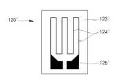
먼저 도 4a에 도시된 바와 같이 안전 소자(120)는 케이스(110)의 표면에 접착되는 절연 필름(123)을 포함할 수 있다. 또한, 상기 절연 필름(123) 위에는 소정 저항값을 갖는 금속선(124)이 형성될 수 있고, 상기 금속선(124)의 양단에는 리드 단자(125)가 형성될 수 있다. 물론, 상기 리드 단자(125)에는 연성 배선 패턴(122)의 배선패턴(122b)이 접속될 수 있다.First, as illustrated in FIG. 4A, the
또한, 도 4b에 도시된 바와 같이 또다른 안전 소자(120')는 케이스(110)의 표면에 접착되는 절연 필름(123')을 포함할 수 있다. 상기 절연 필름(123') 위에는 소정 저항값을 갖는 금속 호일(124')이 형성될 수 있고, 상기 금속 호일(124')의 양단에는 리드 단자(125')가 형성될 수 있다. 상술한 바와 같이 상기 리드 단자(125')에는 연성 배선 패턴(122)의 배선패턴(122b)이 전기적으로 접속될 수 있다.In addition, as shown in FIG. 4B, another
더불어, 도 4c에 도시된 바와 같이 또다른 안전 소자(120")는 케이스(110)의 표면에 접착되는 절연 필름(123")을 포함할 수 있다. 또한, 상기 절연 필름(123") 위에는 소정 저항값을 갖는 n형 또는 p형 반도체 띠(124")가 형성될 수 있고, 상기 반도체 띠(124")의 양단에는 리드 단자(125")가 형성될 수 있다. 이러한 리드 단자(125")에도 상술한 바와 같이 연성 배선 패턴(122)의 배선패턴(122b)이 전기적으로 접속될 수 있다.In addition, as shown in FIG. 4C, another
여기서, 본 발명에 이용된 모든 안전 소자는 소위 표면 변형(케이스의 스웰링)을 측정하는데 이용되는 스트레인 게이지일 수 있으나, 이러한 종류로 본 발명을 한정하는 것은 아니다. 즉, 표면 변형을 감지하거나 측정할 수 있는 부재이면 모두 가능하다. 또한, 상기 변형량은 원래 길이에 대한 변화된 길이의 비이므로, 안전 소자가 부착되어 있는 케이스(110)의 길이 변화를 절연 필름(123)위에 형성된 금속선(124), 금속호일(124') 또는 반도체 띠(124") 등의 저항 변화로서 감지하게 된다. 즉, 상기 케이스(110)의 스웰링시 상기 금속선(124), 금속 호일(124') 또는 반도체 띠(124") 등의 저항값이 증가 또는 감소함으로써, 이를 보호회로기판(130)에 알려주고, 이로 인하여 보호회로기판(130)이 충방전을 위한 대전류를 감소시키거나 차단하게 되는 것이다.Here, all the safety elements used in the present invention may be strain gauges used to measure so-called surface deformation (swelling of the case), but the present invention is not limited to this kind. In other words, any member capable of detecting or measuring surface deformation is possible. In addition, since the deformation amount is a ratio of the changed length to the original length, the change in length of the
일례로, 상기 안전 소자(120)는 케이스(110)의 표면이 변형(strain) 즉, 스웰링되면 그 저항값이 변화(증가)하게 되고, 전체 저항(R)에 대한 저항 변화(△R)의 비율이 변형량(ε)에 비례하는 특징을 갖고 있다. 즉, 상기 안전 소자(120)는 수식으로 표현하면 △R/R=Gε인 특징을 갖는다. 여기서 상기 G는 게이지 상수이며, 이는 대략 1~1000 단위를 가질 수 있다. 일례로 상기 안전 소자(120)의 원래 저항값이 10Ω이고, 게이지 상수가 100이며, 변형량 또는 스웰링량이 0.1인 경우 저항 변화는 100×0.1×10=100Ω이 된다. 즉, 스웰링이 없을 경우 안전 소자(120)의 저항값은 10Ω이었지만, 0.1이라는 값으로 스웰링이 발생하면 안전 소자(120)의 저항값은 100Ω으로 증가한다. 따라서, 전류는 저항값과 반비례 관계이므로 상기 안전 소자(120)를 통하여 흐르는 전류는 대략 10배 감소하게 된다. 물론, 이러한 안전 소자(120)의 원래 저항값, 게이지 상수 및 스웰링값은 모두 예시값일 뿐이며, 이러한 값들은 소자 설계시 각종 변수를 조정함으로서 충분히 변경 가능하다. 그러나, 상기 안전 소자(120)의 원래 저항값은 높으면 높을수록 보호회로기판(130)에서 사용되는 소비 전류가 커지므로, 이차 전지(100)의 설계자는 이를 되도록 작은 값으로 설계함이 바람직하다. 또한, 케이스(110)의 스웰링에 민감하게 저항값이 증가되어야 급격한 스웰링 상태에서 전류를 차단할 수 있기 때문에, 이차 전지(100)의 설계자는 상기 게이지 상수가 되도록 높은 것을 이용함이 바람직하다.For example, when the surface of the
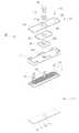
도 5를 참조하면, 본 발명의 이차 전지에서 베어 셀만을 도시한 분해 사시도가 도시되어 있다. 통상 이차 전지(100)에서 베어 셀(BC)이라고 하면, 보호회로기판(130) 등이 장착되지 않은 상태를 말한다. 따라서, 상기 도면에서도 보호회로기판(130) 및 안전 소자(120)는 도시되어 있지 않다. 또한, 상기한 바와 같은 베어 셀(BC)은 본 발명에 의한 이차 전지(100)의 전체적 이해를 위한 일례일 뿐이며 여기에 개시된 베어 셀(BC)의 구성으로 본 발명을 한정하는 것은 아니다. 즉, 본 발명에서 채택된 안전 소자(120)는 도시된 베어 셀(BC)에만 접착될 수 있는 것은 아니며, 도시되지 않은 다양한 형태의 베어 셀(BC)에 모두 접착되어 사용될 수 있다.Referring to FIG. 5, an exploded perspective view illustrating only a bare cell in a secondary battery of the present invention is illustrated. In general, the bare cell BC in the
도시된 바와 같이 베어 셀(BC)은 소정 에너지로 충전되거나 이것을 방출하는 전극 조립체(10), 상기 전극 조립체(10)가 수납되는 케이스(110), 상기 케이스(110)의 상부에 조립되어 상기 전극 조립체(10)가 이탈되지 않도록 하는 캡 조립체(20), 상기 케이스(110)에 주입되어 전극 조립체(10) 사이에 이온 이동이 가능하게 하는 전해액(도시되지 않음)을 포함할 수 있다.As shown, the bare cell BC is assembled with an
상기 전극 조립체(10)는 양극 활물질(예를 들면 코발트산리튬(LiCoO2), 니켈산리튬(LiNiO2), 망간산리튬(LiMn2O4) 또는 그 등가물)이 부착된 양극 전극판(11), 음극 활물질(예를 들면 흑연 또는 그 등가물)이 부착된 음극 전극판(13) 및 양극 전극판(11)과 음극 전극판(13) 사이에 위치되어 쇼트를 방지하고 리튬 이온의 이동만 가능하게 하는 세퍼레이터(12)로 이루어질 수 있으며, 위의 양극 전극판(11), 음극 전극판(13) 및 그 사이에 개재된 세퍼레이터(12)는 대략 젤리 롤(jelly roll) 형태로 권취되어 케이스(110)에 수납될 수 있다. 여기서, 상기 양극 전극판(11)은 알루미늄(Al) 포일, 상기 음극 전극판(13)은 구리(Cu) 포일, 상기 세퍼레이터(12)는 폴리에틸렌(PE) 또는 폴리프로필렌(PP)일 수 있으나, 본 발명에서 위의 재질을 한정하는 것은 아니다. 또한, 상기 양극 전극판(11)에는 상부로 일정 길이 돌출된 양극 리드(14)가 용접될 수 있고, 상기 음극 전극판(13)에도 상부로 일정 길이 돌출된 음극 리드(15)가 용접될 수 있다. 상기 양극 리드(14)는 알루미늄(Al) 재질, 상기 음극 리드(15)는 니켈(Al) 재질일 수 있으나, 본 발명에서 위의 재질을 한정하는 것은 아니다.The
상기 케이스(110)는 위에서 상세히 설명한 바와 같이 일정 면적을 가지며 상호 대향되는 위치에 형성된 제1영역(111), 상기 제1영역(111) 사이로서 상호 대향되는 위치에 형성된 동시에 상기 제1영역(111)의 면적보다 작은 면적을 갖는 제2영역(112), 상기 제1영역(111)과 제2영역(112)을 막는 제3영역(113)으로 이루어질 수 있으며, 상기 제3영역(113)의 반대 방향에는 상기 제1영역(111)과 제2영역(112) 사이의 공간과 연통되는 개구부(110a)가 형성될 수 있다.As described in detail above, the
한편, 상기 전극 조립체(10)의 상부로서 상기 케이스(110)의 상부에는 순차적으로 절연 케이스(21), 단자 플레이트(22), 절연 플레이트(23)가 더 결합될 수 있으나, 본 발명에서 이러한 구성 요소를 반듯이 필요로 하는 것은 아니다. 물론, 상기 절연 케이스(21), 단자 플레이트(22) 및 절연 플레이트(23)는 전극 단자(116)가 상부로 연장되어 관통될 수 있도록 통공(21a,22a,23a)이 각각 형성될 수 있다.Meanwhile, the insulating
상기 캡 조립체(20)는 상기 케이스(110)의 개구부(110a)에 조립될 수 있다. 즉, 상기 캡 조립체(20)는 대략 판상의 캡 플레이트(115)가 구비되고, 상기 캡 플레이트(115)의 중앙에는 일정 크기의 통공(115a)이 형성되며, 그 측부에는 전해액 주입을 위한 전해액 주입구(115b)가 형성될 수 있다. 물론, 이러한 캡 플레이트(115)의 구조도 위에서 상세히 설명한바 있다. 더욱이, 상기 캡 플레이트(115)의 통공(115a)에는 절연 가스켓(119)이 결합되고, 상기 절연 가스켓(119)에는 전극 단자(116)가 결합될 수 있다. 물론, 상기 전극 단자(116)는 상기 음극 리드(15)와 용접되어 방전 또는 충전시 음극 역할을 할 수 있다. 또한, 상기 양극 리드(14)는 상기 캡 플레이트(115)에 직접 용접됨으로써, 상기 캡 플레이트(115) 및 케이스(110) 는 양극 역할을 수행할 수 있다. 물론, 상기 전극 단자(116)에는 양극 리드(14)가 결합되어 양극 역할을 하고, 상기 캡 플레이트(115)는 음극 리드(15)가 용접되어 음극 역할을 할 수도 있다.The
더불어, 상기 캡 플레이트(115)의 전해액 주입구(115b)에도 전해액 주입후, 그 전해액이 외부로 유출되지 않도록 볼(115c)이 결합될 수 있고, 또다른 일측에는 과도한 스웰링시 오픈되도록 상대적으로 얇은 안전 벤트(118)가 형성될 수 있다.In addition, after the electrolyte is injected into the
한편, 도시되지 않은 전해액은 충방전시 전지 내부의 양극 및 음극에서 전기화학적 반응에 의해 생성되는 리튬 이온의 이동 매체 역할을 하며, 이는 리튬염과 고순도 유기 용매류의 혼합물인 비수질계 유기 전해액일 수 있다. 더불어, 상기 전해액은 고분자 전해질을 이용한 폴리머일 수도 있다.On the other hand, the electrolytic solution (not shown) serves as a moving medium of lithium ions generated by the electrochemical reaction at the positive and negative electrodes inside the battery during charge and discharge, which is a non-aqueous organic electrolyte that is a mixture of lithium salts and high purity organic solvents. Can be. In addition, the electrolyte may be a polymer using a polymer electrolyte.
다시한번 설명하지만, 이러한 구조의 베어셀(BC)로 본 발명을 한정하는 것은 아니다. 즉, 본 발명에 개시된 안전 소자(120,10',120")는 상술한 구조와 같은 베어셀(BC) 뿐만 아니라 스웰링 현상이 발생하는 전지이면 모든 종류의 전지에 접착되어 사용될 수 있다.Again, the present invention is not limited to the bare cell BC having such a structure. That is, the
도 6a를 참조하면, 본 발명에 따른 이차 전지가 스웰링된 상태의 사시도가 도시되어 있고, 도 6b를 참조하면, 그 측면도가 도시되어 있다.Referring to FIG. 6A, a perspective view of a state in which a secondary battery according to the present invention is swelled is illustrated. Referring to FIG. 6B, a side view thereof is illustrated.
도시된 바와 같이 일반적으로 이차 전지(100)는 과충전, 과방전, 외부 쇼트, 내부 쇼트 및 외부 열기 등에 의해 내부의 전해액 등이 분해되며 가스를 방출함으로써, 스웰링 현상이 발생한다. 이러한 스웰링은 일반적으로 넓은 영역이 바깥 방 향으로 부풀어 오르고, 상대적으로 좁은 영역이 안쪽으로 들어간다. 즉, 서로 대향되는 제1영역(111)은 대략 중앙 부분이 바깥 방향으로 부풀어 오른다. 이와 반대로, 서로 대향되는 제2영역(112)은 대략 중앙 부분이 내측 방향으로 움푹 들어간다. 또한, 제3영역(113)도 마찬가지로 대략 중앙 부분이 내측 방향으로 움푹 들어간다. 물론, 상기 제1영역(111)이 면적이 가장 넓음으로써, 스웰링 현상이 가장 심하게 발생하며, 제2영역(112) 및 제3영역(113)은 그 스웰링 현상이 작게 발생한다. 따라서, 이러한 스웰링에 가장 민감하게 반응하는 제1영역(111)의 대략 중앙 또는 4개의 모서리 근방에 안전 소자(120)가 접착될 수 있다. 실제로 스웰링에 관한 시뮬레이션 결과에서는 4개의 모서리 근방에서 연신률 변화가 가장 크게 나타난다고 보고된바 있다. 따라서, 바람직하기로는 도면과는 다르게 4개의 모서리 근방에 안전 소자(120)가 부착될 수 있다. 이와 같이 하여, 본 발명에 개시된 안전 소자(120)는 스웰링에 가장 민감하게 반응하고, 이에 따라 이러한 정보를 보호회로기판(130)에 신속히 전달함으로써, 보호회로기판(130)이 즉각적으로 이차 전지의 충방전을 정지시키게 된다.As shown in the drawing, generally, the
한편, 이러한 스웰링은 케이스(110)의 표면과 안전 소자(120) 상호간의 접착력을 떨어뜨릴 수 있다. 따라서, 상술한 바와 같이 케이스(110)와 안전 소자(120)를 접착시키는 접착제(121)는 강력할 수록 좋으며, 또한 케이스(110)와 안전 소자(120) 상호간에 균일하게 도포됨이 좋다. 상기 접착제(121)의 접착력이 약하면 약한 스웰링시에도 상기 안전 소자(120)가 케이스(110)로부터 분리됨으로써, 케이스(110)의 스웰링을 적절히 감지할 수 없다. 또한, 접착제(121)가 안전 소자(120)의 전영역에 걸쳐 균일하게 도포되어 있지 않으면 안전 소자(120)에 의한 스웰링 감지도가 저하된다.On the other hand, such swelling may reduce the adhesion between the surface of the
더불어, 상기와 같은 스웰링은 이차 전지의 용량에 관계없이 거의 같은 패턴으로 발생한다. 즉, 가장 넓은 부분이 바깥쪽으로 부풀고, 상대적으로 좁은 부분이 안쪽으로 움푹 들어간다. 따라서 본 발명에 개시된 안전 소자는 전지의 용량에 따라 그 규격 등을 변경할 필요가 없다. 예를 들면, 원래의 저항 및 게이지 상수 등을 전지의 용량마다 바꾸어 설계 및 제작할 필요가 없다. 물론, 온도에 관계없이 스웰링에 직접 감응하여 작동함으로써, 이차 전지의 안전성은 더욱 향상된다. 더욱이 상기와 같은 스웰링은 내부 온도의 급상승과 함께 즉각적으로 발생함으로써, 내부 온도를 감지하는 것보다 이에 수반하는 스웰링 현상을 감지함으로써, 내부 온도의 급상승 내지 스웰링 현상을 신속하게 억제할 수 있게 된다. 또한, 상기와 같은 스웰링은 허용 온도 이하에서도 발생할 수 있는데, 본 발명은 이러한 허용 온도 이하에서 발생하는 스웰링 현상도 신속하게 억제할 수 있게 된다. 물론, 상기 안전소자는 충방전 위한 대전류 경로가 아닌 보호회로 작동을 위한 소전류 경로에 연결됨으로써, 안전 소자에 의한 이차 전지 자체의 소비 전력이 크게 저하된다.In addition, such swelling occurs in almost the same pattern regardless of the capacity of the secondary battery. That is, the widest part bulges outward, and the relatively narrow part dents inward. Therefore, the safety element disclosed in the present invention does not need to change its standard or the like according to the capacity of the battery. For example, there is no need to design and manufacture by changing the original resistance, gauge constant, and the like for each battery capacity. Of course, by operating directly in response to swelling regardless of temperature, the safety of the secondary battery is further improved. Furthermore, such swelling occurs immediately with the rise of the internal temperature, so that the swelling phenomenon accompanying it is detected rather than sensing the internal temperature, so that the rapid rise or swelling of the internal temperature can be suppressed quickly. do. In addition, the swelling as described above can occur even below the allowable temperature, the present invention can also quickly suppress the swelling phenomenon occurring below this allowable temperature. Of course, the safety device is connected to the small current path for the protection circuit operation, not the large current path for charging and discharging, so that the power consumption of the secondary battery itself by the safety device is greatly reduced.
도 7을 참조하면, 본 발명의 다른 실시예에 따른 이차 전지의 사시도가 도시되어 있고, 도 8을 참조하면, 도 7의 7-7선 단면도가 도시되어 있다.Referring to FIG. 7, a perspective view of a rechargeable battery according to another exemplary embodiment of the present invention is illustrated, and referring to FIG. 8, a cross-sectional view taken along line 7-7 of FIG. 7 is illustrated.
또한, 도 9a를 참조하면, 도 7의 분해 사시도가 도시되어 있고, 도 9b를 참조하면, 보호회로기판의 후면 사시도가 도시되어 있다.9A, an exploded perspective view of FIG. 7 is shown, and with reference to FIG. 9B, a rear perspective view of the protective circuit board is shown.
이러한 이차 전지(200)은 상술한 이차 전지(100)와 유사하므로, 그 차이점을 중심으로 설명하기로 한다.Since the
도시된 바와 같이 본 발명의 다른 실시예 의한 이차 전지(200) 역시 양극 및 음극을 갖는 케이스(210)와, 상기 케이스(210)의 표면에 접착되어 스웰링시 저항값이 변하는 안전 소자(220)와, 상기 케이스(210)의 일측에 장착되어 상기 안전 소자(220)와 전기적으로 연결된 보호회로기판(230)을 포함할 수 있다.As shown, the
상기 케이스(210)은 일정 면적의 제1영역(211), 상기 제1영역(211)의 둘레에 상대적으로 작은 면적을 갖는 제2영역(212) 및 상기 제1영역(211) 및 제2영역(212)을 막는 제3영역(213)을 포함할 수 있다. 물론, 상기 제3영역(213)에는 상대적으로 얇은 안전 벤트(214)가 형성될 수 있으며, 이러한 안전 벤트(214)는 과도한 스웰링시 파열되어 내부 가스가 방출되도록 하는 역할을 한다.The
상기 제3영역(213)의 반대 방향에는, 상기 제1영역(211)과 제2영역(212)에 대략 직각 방향으로 캡 플레이트(215)가 고정될 수 있다. 상기 캡 플레이트(215)는 대략 중앙에 전극 단자(216)가 형성될 수 있고, 그 양측에는 도전 플레이트(217) 및 안전 벤트(218)가 형성될 수 있다. 더불어, 상기 전극 단자(216)의 외주연에는 절연 가스켓(219)이 형성되어, 상기 전극 단자(216)와 상기 캡 플레이트(215)가 상호 전기적으로 쇼트되지 않도록 할 수 있다.In the opposite direction of the
상기 안전 소자(220)는 상기 케이스(210)의 제2영역(212)에 접착될 수 있다. 예를 들면, 상기 안전 소자(220)는 상기 케이스(210)의 제2영역(212) 중앙에 접착되거나 또는 대각선이 이루는 교차 지점에 접착될 수 있으나, 이러한 접착 위치로 본 발명을 한정하는 것은 아니다. 더욱이, 상기 안전 소자(220)는 어느 일측의 제2영역(212)에만 접착되거나 또는 양측의 제2영역(212)에 모두 접착될 수 있다. 더불어, 도면에서는 상기 안전 소자(220)가 하나만 도시되어 있지만, 이러한 안전 소자(220)는 케이스(210)의 표면에 다수개가 접착될 수 있으며, 그 개수를 한정하는 것도 아니다.The
이러한 안전 소자(220)는 저항값이 케이스(210)의 스웰링에 비례하여 변하는 특성을 가질 수 있다. 예를 들어, 케이스(210)의 스웰링이 없으면 거의 저항값이 존재하지 않고, 스웰링이 작으면 저항값이 작으며, 스웰링이 크면 저항값이 큰 특성을 가질 수 있다. 다른 말로 하면, 상기 안전 소자(220)는 케이스(210)의 스웰링이 없을 때 입력되는 전류를 그대로 통과시키고, 스웰링이 작으면 상대적으로 작은 전류를 흘리며, 스웰링이 특정치 이상이 되면 전류를 통과시키지 않게 된다.The
더불어, 상기 안전 소자(220)를 케이스(210)의 표면에 접착시키는 접착제(221)는 통상의 강력 접착제, 양면 접착 테이프 또는 양면 접착 필름중 선택된 어느 하나가 이용될 수 있으나, 본 발명에서 이를 한정하는 것은 아니다. 물론, 상기 안전 소자(220)는 상기 케이스(210)의 스웰링에 민감하게 반응하는 것이므로, 상기 안전 소자(220)와 케이스(210) 사이의 접착력은 균일한 동시에 우수할수록 좋다.In addition, the adhesive 221 for adhering the
또한, 상기 안전 소자(220)는 연성 배선 패턴(222)을 통하여 상기 보호회로기판(230)에 전기적으로 연결될 수 있다. 즉, 상기 연성 배선 패턴(222)은 쉽게 구부릴 수 있고, 또한 상기 케이스(210)와 전기적으로 도통되지 않기 때문에 종래의 리드 연결 방식보다 안정적이다. 더욱이, 상기 안전 소자(220)는 상기 보호회로기 판(230)에 구비된 소전류 경로에 연결된다. 따라서, 상기 안전소자(220)에 의한 전력 소모량은 최소화된다. 한편, 이러한 연성 배선 패턴(222)은 도시된 바와 같이 상기 케이스(210)의 표면에 접착제(221)로 접착된 제1절연층(222a)과, 상기 제1절연층(222a)에 형성되어 있되, 일단은 상기 안전 소자(220)에 전기적으로 접속되고, 타단은 보호회로기판(230)에 전기적으로 접속된 배선 패턴(222b)과, 상기 배선 패턴(222b)을 외부 환경으로부터 보호하기 위해 상기 배선 패턴(222b)을 덮는 제2절연층(222c)을 포함하여 이루어질 수 있다.In addition, the
상기 보호회로기판(230)은 상기 케이스(210)의 일측에 기계적으로 연결되고, 상기 안전 소자(220)와는 전기적으로 연결되어 있다. 즉, 상기 보호회로기판(230)은 상기 캡 플레이트(215)의 일측에 위치되어 있으며, 이것은 상기 안전 소자(220)와 전기적으로 연결될 수 있도록 적어도 하나 이상의 도전 단자(231)가 상기 캡 플레이트(215)를 향하여 돌출되어 있다. 물론, 상기 보호회로기판(230)에는 충전 및 방전 동작을 제어하는 전자 부품(233)이 실장되어 있으며, 상기 도전 단자(231)는 상기 전자 부품(233)과 전기적으로 연결되어 있다. 좀더 구체적으로 상기 도전 단자(231)는 상기 연성 배선 패턴(222)에 전기적으로 접속될 수 있다. 물론, 이러한 도전 단자(231) 역시 소전류 경로 사이에 설치됨은 당연하다. 더욱이, 상기 보호회로기판(230)에는 상기 캡 플레이트(215) 및 전극 단자(216)에 전기적으로 연결될 수 있도록 또다른 도전 단자(232)가 형성될 수 있다. 물론, 상기 도전 단자(232)와 상기 캡 플레이트(215) 및 전극 단자(216)가 용이하게 본딩될 수 있도록 적어도 하나 이상의 도전 리드(234)가 형성될 수 있다. 물론, 상기 도전 리드(234)중 어느 하나는 캡 플레이트(215)에 구비된 전극 단자(216)에 용접되고, 다른 하나는 상술한 바와 같이 도전 플레이트(217)에 용접된다.The
또한, 상기 보호회로기판(230)은 상기 캡 플레이트(215)를 향하는 반대면에 다수의 외부 단자(235)가 형성될 수 있으며, 이러한 외부 단자(235)는 외부 장치에 직접 전기적으로 연결되는 부분이다. 한편, 이와 같은 보호회로기판(230)은 하나의 예에 불과하며, 상기 연성 배선 패턴(222)이 연결되는 도전 단자(231), 상기 전극 단자(216) 및 캡 플레이트(215)에 용접되는 또다른 도전 단자(232), 전자 부품(233)의 배열 및 외부 단자(235)의 개수 및 형태는 얼마든지 변경 가능하다. In addition, the
한편, 상기 캡 플레이트(215)와 보호회로기판(230) 사이에는 상기 캡 플레이트(215)로부터 보호회로기판(230)이 외부로 이탈되지 않도록 대략 직사각형 모양의 절연 수지링(240)이 더 형성될 수 있다. 물론, 이러한 절연 수지링(240)은 상기 캡 플레이트(215)와 보호회로기판(230) 사이의 틈으로 이물질 등이 침투하지 않도록 하는 역할을 한다.Meanwhile, an insulating
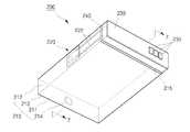
도 10a를 참조하면, 본 발명에 따른 이차 전지가 스웰링된 상태의 사시도가 도시되어 있고, 도 10b를 참조하면, 그 정면도가 도시되어 있다.Referring to FIG. 10A, a perspective view of a state in which a secondary battery according to the present invention is swelled is illustrated. Referring to FIG. 10B, a front view thereof is illustrated.
도시된 바와 같이 일반적으로 이차 전지(200)는 과충전, 과방전, 외부 쇼트, 내부 쇼트, 외부 열기 등에 의해 내부의 전해액이 분해되며 가스를 방출함으로써, 스웰링 현상이 발생한다. 이러한 스웰링은 일반적으로 넓은 영역이 바깥 방향으로 부풀어 오르고, 상대적으로 좁은 영역이 안쪽으로 들어간다. 즉, 서로 대향되는 제1영역(211)은 대략 중앙 부분이 바깥 방향으로 부풀어 오른다. 이와 반대로, 서로 대향되는 제2영역(212)은 대략 중앙 부분이 내측 방향으로 들어간다. 또한, 제3영역(213)도 마찬가지로 대략 중앙 부분이 내측 방향으로 들어간다. 물론, 상기 제1영역(211)이 면적이 가장 넓음으로써, 스웰링 현상이 가장 심하게 발생하며, 제2영역(212) 및 제3영역(213)은 그 스웰링 현상이 작게 발생한다. 따라서, 이러한 스웰링에 가장 민감하게 반응하는 제1영역(211)에 안전 소자(220)가 접착될수 있으나, 이 경우 상기 스웰링에 너무 민감하게 안전 소자(220)가 작동함으로써, 오히려 이차 전지의 작동을 불안정하게 할 수 있다. 즉, 허용 가능한 스웰링 상태에서도 보호회로(230)가 대전류를 너무 급격히 저하시킴으로써, 오히려 충, 방전 동작을 방해할 수 있다. 따라서, 이러한 경우에는 상술한 바와 같이 스웰링이 덜 발생하는 케이스(210)의 제2면에 안전 소자(220)를 접착시킴으로써, 이러한 문제를 해소할 수 있게 된다.As shown in the drawing, generally, the
한편, 이러한 스웰링은 케이스(210)의 표면과 안전 소자(220) 상호간의 접착력을 떨어뜨릴 수 있다. 따라서, 상술한 바와 같이 케이스(210)과 안전 소자(220)를 접착시키는 접착제(221)는 강력할 수도록 좋으며, 또한 케이스(210)과 안전 소자(220) 상호간에 균일하게 도포됨이 좋다. 상기 접착제(221)의 접착력이 약하면 약한 스웰링시에도 상기 안전 소자(220)가 케이스(210)으로부터 분리됨으로써, 케이스(210)의 스웰링을 적절히 감지할 수 없다. 또한, 접착제(221)가 안전 소자(220)의 전영역에 걸쳐 균일하게 도포되어 있지 않으면 안전 소자(220)에 의한 스웰링 감지도가 저하된다.On the other hand, such swelling may reduce the adhesion between the surface of the
도 11을 참조하면, 본 발명에 따른 이차 전지의 구성이 블록도로서 도시되어 있다.Referring to Figure 11, the configuration of a secondary battery according to the present invention is shown as a block diagram.
도시된 바와 같이 본 발명에 따른 이차 전지를 전기적 회로 관점에서 보면, 베어 셀(BC)과, 상기 베어 셀(BC)의 어느 한 극에 연결된 온도 퓨즈(151)와, 상기 온도 퓨즈(151)에 직렬 연결된 충방전 FET 소자(152,153)와, 상기 베어 셀(BC)의 다른 극에 연결된 센서 저항(155)과, 상기 베어 셀(BC)에 물리적으로 접착된 안전 소자(120)와, 상기 베어 셀(BC), 센서 저항(155) 및 안전 소자(120)로부터 전압, 전류 및 스웰링 상태 정보를 입력받아 상기 충방전 FET 소자(152,153)를 제어하는 보호회로(154)와, 상기 충방전FET 소자(152,153) 및 센서 저항(155) 사이에 형성된 외부 단자(135)를 포함한다. 여기서, 상기 보호회로(154)는 베어 셀(BC)로 직접 전압 정보를 입력받고, 상기 센서 저항(155)으로부터 전류 정보를 입력받으며, 상기 안전 소자(120)로부터 스웰링 정보를 입력받는다.As shown, a secondary battery according to the present invention is viewed from an electrical circuit point of view, in a bare cell BC, a
상기 온도 퓨즈(151), 충방전 FET 소자(152,153), 센서 저항(155), 보호회로(154) 및 외부 단자(135)는 상술한바와 같은 보호회로기판(130)에 형성될 수 있고, 상기 안전 소자(120)는 상술한바와 같이 베어셀(BC)을 이루는 케이스(110)의 표면에 접착되어 형성될 수 있다.The
상기와 같이 구성된 본 발명에 따른 이차 전지에서는 외부 단자(135)를 통해 외부의 충전기 또는 부하(도면에 도시되지 않음)가 연결되어 충전 또는 방전 동작이 수행된다. 상기 외부 단자(135)와 베어 셀(BC) 사이의 경로는 충방전 경로로 사용되는 대전류 경로이며, 이 대전류 경로에는 비교적 큰 전류가 흐른다.In the secondary battery according to the present invention configured as described above, an external charger or load (not shown) is connected through an
상기 외부 단자(135)에 충전기가 연결되어 베어 셀(BC)의 충전동작이 수행되면, 이 때의 충전 경로는 충전기를 시작으로 하여 외부 단자(135), 방전 FET 소자(153), 충전 FET 소자(152) 및 온도 퓨즈(151)를 거쳐 베어 셀(BC)로 이어진다. 그 반대로 외부 단자(135)에 부하가 연결되어 방전 동작이 수행되면, 이때의 방전 경로는 베어 셀(BC), 온도 퓨즈(151), 충전 FET 소자(152), 방전 FET 소자(153) 및 외부 단자(135)를 거쳐 부하로 이어진다. 즉, 본 발명에서 안전 소자(120)는 대전류 경로에서 제외되고, 따라서 그만큼 충전기의 소비 전력이 감소함을 알 수 있다.When the charger is connected to the
한편, 상기 베어 셀(BC)은 자체 충전 전압을 보호회로(154)에 직접 출력하고, 상기 센서 저항(155)은 베어 셀(BC)의 충전 전류를 감지하여 보호회로(154)에 출력한다. 따라서, 상기 베어 셀(BC)이 현재 과충전 전압 또는 과전류로 충전되는 상태이면, 상기 보호회로(154)는 충전 FET 소자(152)를 오프시킴으로서, 대전류 경로에서 충전 전류 흐름을 차단하고, 따라서 과충전 상태가 해제된다.Meanwhile, the bare cell BC directly outputs its own charging voltage to the
또한, 상기 베어 셀(BC)은 자체 방전 전압을 보호회로(154)에 직접 출력하고, 상기 센서 저항(155)은 베어 셀(BC)의 방전 전류를 감지하여 보호회로(154)에 출력한다. 따라서, 상기 베어 셀(BC)이 현재 과방전 전압 또는 과전류(또는 외부 단락)로 방전되는 상태이면, 상기 보호회로(154)이 방전 FET 소자(153)를 오프시킴으로서, 대전류 경로에서 방전 전류 흐름을 차단하고, 따라서 과방전 상태가 해제된다.In addition, the bare cell BC directly outputs its own discharge voltage to the
더불어, 상술한 충전 FET 소자(152) 및 방전 FET 소자(153)는 대전류가 흐르고 또한 소정 저항 성분이 있기 때문에 충방전 도중 과열되는 경우가 있다. 이와 같은 과열 현상은 일반적으로 상기 충전 FET 소자(152) 및 방전 FET 소자(153)가 정상적으로 온, 오프되지 않도록 하는 한 요인이 된다. 즉, 보호회로(154)에서 충전 FET 소자(152) 또는 방전 FET 소자(153)에 오프신호를 주워도 오프되지 않게 된다. 따라서, 이때는 다른 방법에 의해 상기 대전류 경로를 차단해야 하는데 이것이 바로 온도 퓨즈(151)이다. 즉, 상기 온도 퓨즈(151)는 상기 충전 FET 소자(152) 및 방전 FET 소자(153) 위에 바로 설치됨으로써, 상기 충전 FET 소자(152) 또는 방전 FET 소자(153)가 과열되었을 때 온도 퓨즈(151) 자체가 끊어지면서 대전류 경로를 차단하게 된다.In addition, the
한편, 상술한 바와 같이 과충전 또는 과방전으로 베어 셀(BC)이 스웰링되거나, 충전 또는 방전 도중 전압 및 전류는 허용치 이하이고, 충전 FET 소자(152) 및 방전 FET 소자(153)의 온도도 허용치 이내이면서 상기 베어 셀(BC)이 스웰링되는 경우가 있다. 물론, 이러한 스웰링이 심할 경우 케이스(110)의 표면에 형성된 안전 벤트(114,118)가 작동하여 내부 가스를 누출시킴으로써, 폭발이나 발화 현상을 방지하고 있지만, 이것은 그다지 안전하다고 볼 수 없다.On the other hand, as described above, the bare cell BC is swelled due to overcharging or overdischarging, or the voltage and current during the charging or discharging are less than the allowable value, and the temperatures of the
따라서, 상기와 같은 스웰링이 과도하게 발생할 때 즉, 과충전이나 과방전에 의한 온도 증가로 스웰링이 발생하거나 또는 과충전, 과방전이 아닌 정상적인 상태에서 어떤 알 수 없는 이유로 스웰링이 과도하게 발생할 때 회로적으로 대전류 경로를 차단하는 부재가 필요한데, 이러한 역할을 하는 부재가 바로 안전 소자(120)이다.Therefore, when such swelling occurs excessively, that is, when swelling occurs due to an increase in temperature due to overcharge or overdischarge, or when swelling occurs excessively for some unknown reason in a normal state other than overcharge or overdischarge, Therefore, a member for blocking a large current path is required, and the member that plays such a role is the
이러한 안전 소자(120)에 대해서는 위에서 이미 상세히 설명하였다. 즉, 이 러한 안전 소자(120)는 베어 셀(BC) 다른 말로 하면 케이스(110)의 표면에 접착되어 그 스웰링 상태를 감지하는 소자이다. 좀더 구체적으로 상기 안전 소자(120)는 베어 셀(BC)이 스웰링될 경우 그 저항값이 변하며, 이러한 변화 상태를 보호회로(154)에 출력한다.This
또한, 상기 보호회로(154)는 위와 같이 안전 소자(120)로부터 입력되는 값이 기준치 이상 또는 이하의 값이면, 충방전 FET 소자(152,153)를 오프시킴으로써, 대전류를 감소시키거나 차단되도록 한다. 따라서, 상기 안전 소자(120)는 과도한 스웰링에 의해 안전 벤트(114,118)가 작동하거나 또는 발화내지 폭발 직전에 대전류 경로에서 전류를 감소시키거나 차단시킴으로써, 베어 셀(BC) 또는 이차 전지(100,200)의 안전성을 더욱 향상시키게 된다. 물론, 상기 블록도에서는 상기 안전 소자(120)가 하나로 도시되어 있으나, 이러한 안전 소자(120)는 다수가 형성될 수 있으며, 여기서 그 개수를 한정하는 것은 아니다.In addition, when the value input from the
상술한 바와 같이 하여, 본 발명은 다양한 전지 용량에 규격 변경없이 사용할 수 있는 안전 소자를 갖는 이차 전지를 제공하게 된다. 다른 말로 하면, 이차 전지의 용량이 각기 다르다고 해도 스웰링 현상은 모두 같은 패턴으로 일어나기 때문에, 동일한 안전 소자를 다양한 용량의 이차 전지에 그대로 사용할 수 있게 된다. 따라서, 이차 전지의 안전 소자를 다양한 규격으로 제조할 필요가 없어 제조 비용을 절감함은 물론, 온도에 관계없이 스웰링에 직접 감응하여 작동함으로써, 이차 전지의 안전성이 더욱 향상되는 효과가 있다.As described above, the present invention provides a secondary battery having a safety device that can be used in various battery capacities without changing specifications. In other words, even if the capacity of the secondary battery is different, the swelling phenomenon occurs in the same pattern, so that the same safety element can be used as it is for secondary batteries of various capacities. Therefore, the safety device of the secondary battery does not need to be manufactured in various standards, thereby reducing manufacturing costs, and operating directly in response to swelling regardless of temperature, thereby further improving the safety of the secondary battery.
또한, 본 발명은 내부 온도의 급상승 및 이에 따른 급속 스웰링 현상도 효율적으로 방지할 수 있게 된다. 즉, 본 발명은 온도를 감지하는 것이 아니라 스웰링 현상을 직접 감지하여 충, 방전 전류를 감소시키거나 차단시키는 것이기 때문에, 즉각적으로 스웰링 현상을 중단시킬 수 있을 뿐만 아니라 이것의 원인인 온도 급상승 현상도 중단시킬 수 있는 효과가 있다.In addition, the present invention can effectively prevent the sudden rise of the internal temperature and the resulting rapid swelling phenomenon. That is, the present invention not only senses the temperature but also directly detects the swelling phenomenon to reduce or cut off the charge and discharge currents, so that the swelling phenomenon can be stopped immediately and the temperature rise phenomenon that is the cause thereof. There is also an effect that can be stopped.
또한, 본 발명은 비록 허용 온도 이하라고 해도 허용 두께 이상으로 스웰링이 발생되는 현상을 방지할 수 있게 된다. 즉, 상술한 바와 같이 본 발명은 온도에 감응하는 것이 아니라 스웰링 두께에 감응하는 것이기 때문에, 온도에 관계없이 스웰링 두께가 허용 두께 이상으로 되기만 하면 충전 또는 방전 전류를 감소시키거나 차단시킴으로써, 이차 전지의 안전성을 더욱 향상시킬 수 있는 효과가 있다.In addition, the present invention can prevent a phenomenon in which swelling occurs above the allowable thickness even if it is below the allowable temperature. That is, as described above, since the present invention is not sensitive to temperature but to swelling thickness, the secondary battery may be reduced or interrupted by reducing or blocking the charging or discharging current as long as the swelling thickness becomes larger than the allowable thickness regardless of the temperature. There is an effect that can further improve the safety of the battery.
더욱이, 본 발명은 안전 소자를 접착제 등으로 케이스의 표면에 접착하고, 연성 배선 패턴을 이용하여 보호회로기판에 전기적으로 접속하면 완성되는 구조로서, 종래와 같이 케이스의 표면에 별도의 도전 플레이트를 용접하고, 또한 이러한 도전 플레이트에 별도의 리드를 용접하는 복잡한 공정이 필요없게 된다. 따라서, 이차 전지의 제조 공정이 단순해지고 이로 인해 제조 비용도 절감되는 효과가 있다.Furthermore, the present invention is a structure that is completed by bonding the safety element to the surface of the case with an adhesive or the like, and electrically connected to the protective circuit board using a flexible wiring pattern, welding a separate conductive plate on the surface of the case as conventionally In addition, there is no need for a complicated process of welding a separate lead to such a conductive plate. Therefore, the manufacturing process of the secondary battery is simplified, thereby reducing the manufacturing cost.
더불어, 본 발명은 안전 소자가 대전류 경로에서 제외됨으로써, 상기 안전 소자에 의한 전력 소비가 없고, 따라서 이차 전지의 용량 및 사용 가능 시간이 증가되는 효과가 있다.In addition, the present invention has the effect that the safety element is excluded from the high current path, there is no power consumption by the safety element, thereby increasing the capacity and usable time of the secondary battery.
이상에서 설명한 것은 본 발명에 따른 이차 전지를 실시하기 위한 하나의 실 시예에 불과한 것으로서, 본 발명은 상기한 실시예에 한정되지 않고, 이하의 특허청구범위에서 청구하는 바와 같이 본 발명의 요지를 벗어남이 없이 당해 발명이 속하는 분야에서 통상의 지식을 가진 자라면 누구든지 다양한 변경 실시가 가능한 범위까지 본 발명의 기술적 정신이 있다고 할 것이다.What has been described above is only one exemplary embodiment for carrying out the secondary battery according to the present invention, and the present invention is not limited to the above-described embodiment, and as claimed in the following claims deviates from the gist of the present invention. Without this, anyone skilled in the art to which the present invention pertains will have the technical spirit of the present invention to the extent that various modifications can be made.
Claims (47)
Translated fromKoreanPriority Applications (4)
| Application Number | Priority Date | Filing Date | Title |
|---|---|---|---|
| KR1020040086897AKR100579377B1 (en) | 2004-10-28 | 2004-10-28 | Secondary battery |
| JP2005049618AJP4603906B2 (en) | 2004-10-28 | 2005-02-24 | Secondary battery |
| US11/211,134US8691408B2 (en) | 2004-10-28 | 2005-08-25 | Secondary battery including protective circuit module to protect battery when swelling occurs |
| CNA2005101183195ACN1767232A (en) | 2004-10-28 | 2005-10-28 | secondary battery |
Applications Claiming Priority (1)
| Application Number | Priority Date | Filing Date | Title |
|---|---|---|---|
| KR1020040086897AKR100579377B1 (en) | 2004-10-28 | 2004-10-28 | Secondary battery |
Publications (2)
| Publication Number | Publication Date |
|---|---|
| KR20060037841A KR20060037841A (en) | 2006-05-03 |
| KR100579377B1true KR100579377B1 (en) | 2006-05-12 |
Family
ID=36262363
Family Applications (1)
| Application Number | Title | Priority Date | Filing Date |
|---|---|---|---|
| KR1020040086897AExpired - Fee RelatedKR100579377B1 (en) | 2004-10-28 | 2004-10-28 | Secondary battery |
Country Status (4)
| Country | Link |
|---|---|
| US (1) | US8691408B2 (en) |
| JP (1) | JP4603906B2 (en) |
| KR (1) | KR100579377B1 (en) |
| CN (1) | CN1767232A (en) |
Cited By (2)
| Publication number | Priority date | Publication date | Assignee | Title |
|---|---|---|---|---|
| KR20140113376A (en)* | 2013-03-14 | 2014-09-24 | 주식회사 엘지화학 | Battery Cell Assembly and Method for Manufacturing the Battery Cell Assembly |
| KR20250079419A (en) | 2023-11-27 | 2025-06-04 | 주식회사 엘지에너지솔루션 | Expansion Detection Member, Battery Pack Comprising Battery Cell with the Expansion Detection Member Attached thereto, and Device with Battery Pack |
Families Citing this family (103)
| Publication number | Priority date | Publication date | Assignee | Title |
|---|---|---|---|---|
| WO2007029941A1 (en)* | 2005-09-07 | 2007-03-15 | Lg Chem, Ltd. | Secondary battery employing safety device |
| KR100770108B1 (en)* | 2005-12-29 | 2007-10-24 | 삼성에스디아이 주식회사 | Battery pack and manufacturing method thereof |
| KR100795682B1 (en)* | 2006-02-27 | 2008-01-21 | 삼성에스디아이 주식회사 | Secondary Battery and Manufacturing Method Thereof |
| USD553563S1 (en)* | 2006-12-20 | 2007-10-23 | Currie Technologies, Inc. | Electric bicycle battery pack |
| US8586221B2 (en) | 2007-01-17 | 2013-11-19 | Samsung Sdi Co., Ltd. | Rechargeable battery with protective circuit board lead plates connection |
| KR100833745B1 (en)* | 2007-01-17 | 2008-05-29 | 삼성에스디아이 주식회사 | Secondary battery |
| FR2912261B1 (en)* | 2007-02-07 | 2009-07-17 | Peugeot Citroen Automobiles Sa | DEVICE FOR PROVIDING ELECTRICAL ENERGY |
| KR100870356B1 (en)* | 2007-03-15 | 2008-11-25 | 삼성에스디아이 주식회사 | Secondary battery |
| CN101286581B (en)* | 2007-04-11 | 2010-05-26 | 有量科技股份有限公司 | Power-off safety structure for overcharge of soft-shell lithium battery |
| CN101640294B (en)* | 2007-04-11 | 2011-09-21 | 有量科技股份有限公司 | Power-off safety structure for overcharge of soft-shell lithium battery |
| KR100917736B1 (en)* | 2007-09-14 | 2009-09-15 | 삼성에스디아이 주식회사 | Battery Pouches and Pouch Type Batteries |
| KR101001315B1 (en)* | 2007-10-18 | 2010-12-14 | 주식회사 엘지화학 | Excellent energy density secondary battery pack and PCM assembly for it |
| JP5108454B2 (en)* | 2007-10-29 | 2012-12-26 | 京セラ株式会社 | Electronics |
| KR101121757B1 (en)* | 2007-11-07 | 2012-03-23 | 에스케이이노베이션 주식회사 | Safety Apparatus and Protection Method of secondary Battery for Electric Vehicle Using Switch |
| US10923776B2 (en)* | 2007-12-31 | 2021-02-16 | Apple Inc. | Systems and methods for monitoring and responding to forces influencing a battery |
| KR100933864B1 (en)* | 2008-03-31 | 2009-12-24 | 삼성에스디아이 주식회사 | Battery pack |
| KR101128423B1 (en)* | 2008-04-28 | 2012-03-23 | 에스케이이노베이션 주식회사 | Safety switch of secondary battery for electric vehicle and charge / discharge system of secondary battery for electric vehicle using same |
| KR100971336B1 (en)* | 2008-06-09 | 2010-07-20 | 삼성에스디아이 주식회사 | Protective circuit module and secondary battery including same |
| US8334063B2 (en) | 2008-09-22 | 2012-12-18 | Samsung Sdi Co., Ltd. | Secondary battery |
| KR101419746B1 (en)* | 2008-10-13 | 2014-07-15 | 주식회사 엘지화학 | SWELLING sensing device of battery cell |
| KR101016849B1 (en)* | 2008-12-03 | 2011-02-22 | 삼성에스디아이 주식회사 | Secondary Battery |
| KR101041153B1 (en)* | 2009-03-04 | 2011-06-13 | 에스비리모티브 주식회사 | Secondary Battery and Its Module |
| US8974942B2 (en) | 2009-05-18 | 2015-03-10 | Gentherm Incorporated | Battery thermal management system including thermoelectric assemblies in thermal communication with a battery |
| KR101030915B1 (en)* | 2009-06-16 | 2011-04-22 | 삼성에스디아이 주식회사 | Battery pack |
| KR20110048774A (en)* | 2009-11-03 | 2011-05-12 | 삼성에스디아이 주식회사 | Cap assembly and secondary battery having the same |
| EP2328210B1 (en)* | 2009-11-25 | 2014-07-30 | Samsung SDI Co., Ltd. | A protection circuit module for a secondary battery |
| US8497035B2 (en)* | 2010-06-23 | 2013-07-30 | GM Global Technology Operations LLC | Battery cell integrated measurement sensor line and equalization resistor |
| KR101209984B1 (en)* | 2010-11-23 | 2012-12-07 | 삼성에스디아이 주식회사 | Battery Pack |
| CN102655061A (en)* | 2011-03-02 | 2012-09-05 | 有量科技股份有限公司 | Charging module with power-off structure |
| KR20120136826A (en)* | 2011-06-10 | 2012-12-20 | 현대자동차주식회사 | Apparatus for preventing from over-charging battery |
| DE112012002935T5 (en) | 2011-07-11 | 2014-05-15 | Gentherm Inc. | Thermoelectric based thermal management of electrical devices |
| WO2011157244A2 (en)* | 2011-08-24 | 2011-12-22 | 华为终端有限公司 | Battery capable of detecting battery core deformation and mobile terminal |
| US9005786B2 (en)* | 2011-10-21 | 2015-04-14 | GM Global Technology Operations LLC | Integrated cell voltage sense line fusing |
| KR101371364B1 (en) | 2011-10-25 | 2014-03-11 | 주식회사 엘지화학 | Top Cap Assembly Comprising Terminal Block |
| EP2645527A1 (en) | 2012-03-26 | 2013-10-02 | Samsung SDI Co., Ltd. | Battery pack |
| DE102012207999A1 (en)* | 2012-05-14 | 2013-11-14 | Robert Bosch Gmbh | Sheath foil for a galvanic cell, electrochemical storage, electrochemical storage system, flexible foil for a sheath of a galvanic cell and method for determining a state quantity of an electrochemical storage |
| KR101836516B1 (en)* | 2012-07-19 | 2018-03-08 | 현대자동차주식회사 | Battery System having Current Interrupt Device and Operation Method thereof |
| KR20140032165A (en)* | 2012-09-06 | 2014-03-14 | 현대자동차주식회사 | Safety apparatus for battery module of electric vehicle |
| KR101918778B1 (en)* | 2012-11-07 | 2018-11-14 | 에스케이이노베이션 주식회사 | Secondary Battery |
| DE112014000419T5 (en) | 2013-01-14 | 2015-10-15 | Gentherm Incorporated | Thermoelectric based thermal management of electrical devices |
| US10270141B2 (en) | 2013-01-30 | 2019-04-23 | Gentherm Incorporated | Thermoelectric-based thermal management system |
| DE102013204523A1 (en)* | 2013-03-15 | 2014-09-18 | Robert Bosch Gmbh | Method and device for increasing the fuse when using battery modules |
| WO2015066079A1 (en) | 2013-10-29 | 2015-05-07 | Gentherm Incorporated | Battery thermal management with thermoelectrics |
| KR20150071571A (en)* | 2013-12-18 | 2015-06-26 | 현대자동차주식회사 | Apparatus for preventing over-charge for battery of vehicle |
| KR101567651B1 (en)* | 2013-12-19 | 2015-11-10 | 현대자동차주식회사 | High voltage battery for vehicle |
| US10312555B2 (en) | 2014-03-31 | 2019-06-04 | Toyo Tire Corporation | Deformation detecting sensor for sealed secondary battery |
| US20170092997A1 (en) | 2014-03-31 | 2017-03-30 | Toyo Tire & Rubber Co., Ltd. | Deformation detection sensor for sealed secondary battery |
| BR112015029581B8 (en) | 2014-04-30 | 2023-03-21 | Lg Chemical Ltd | BATTERY PACK COMPRISING A BAG SECONDARY BATTERY |
| JP6265847B2 (en) | 2014-06-27 | 2018-01-24 | 東洋ゴム工業株式会社 | Deformation detection sensor for sealed secondary battery, sealed secondary battery, and deformation detection method for sealed secondary battery |
| EP3163649B1 (en) | 2014-06-30 | 2019-03-27 | Toyo Tire & Rubber Co., Ltd. | Sensor for detecting deformation of sealed secondary battery, sealed secondary battery, and method for detecting deformation of sealed secondary battery |
| JP6176632B2 (en)* | 2014-06-30 | 2017-08-09 | 東洋ゴム工業株式会社 | Abnormality determination method for assembled battery and abnormality determination device for assembled battery |
| CN106717139B (en) | 2014-09-12 | 2019-07-12 | 詹思姆公司 | Graphite thermoelectric and/or resistive thermal management systems and methods |
| US11079212B2 (en) | 2014-10-24 | 2021-08-03 | Qnovo Inc. | Circuitry and techniques for determining swelling of a battery/cell and adaptive charging circuitry and techniques based thereon |
| US10158149B2 (en) | 2014-11-20 | 2018-12-18 | Motorola Solutions, Inc. | Method and apparatus to detect and manage battery pack cell swell |
| CN104485490A (en)* | 2014-12-12 | 2015-04-01 | 中国科学院电工研究所 | On-line flexible package polymer lithium battery pack monitoring system and monitoring method thereof |
| KR101685130B1 (en)* | 2014-12-19 | 2016-12-09 | 주식회사 엘지화학 | Apparatus and Method for controlling power for secondary battery |
| JP6686286B2 (en)* | 2015-03-30 | 2020-04-22 | 三洋電機株式会社 | Prismatic secondary battery and assembled battery using the same |
| KR102442187B1 (en)* | 2015-04-10 | 2022-09-07 | 삼성에스디아이 주식회사 | Battery protection circuit |
| KR102701512B1 (en)* | 2015-08-25 | 2024-09-03 | 겔리온 테크놀로지스 피티와이 리미티드 | Battery sensor |
| KR101950463B1 (en)* | 2015-10-06 | 2019-02-20 | 주식회사 엘지화학 | Battery Module Having Prove for Sensing Expansion of Battery Cell |
| KR102010012B1 (en)* | 2015-11-26 | 2019-08-12 | 주식회사 엘지화학 | Battery pack comprising fire extinguishing apparatus and controlling method using the same |
| CN108701876B (en)* | 2016-02-17 | 2021-06-22 | 丰田自动车欧洲公司 | System and method for battery discharge control |
| CN105647460A (en)* | 2016-03-31 | 2016-06-08 | 东莞新能源科技有限公司 | A kind of secondary battery and preparation method thereof |
| KR102000632B1 (en)* | 2016-06-09 | 2019-10-01 | 주식회사 엘지화학 | Thickness change measurement apparatus for electrode of secondary battery and secondary battery mounting the same |
| KR102283788B1 (en)* | 2016-09-21 | 2021-07-30 | 삼성에스디아이 주식회사 | Rechargeable battery |
| KR102183995B1 (en) | 2016-10-31 | 2020-11-27 | 삼성에스디아이 주식회사 | Battery pack |
| DE102017206663A1 (en) | 2017-04-20 | 2018-10-25 | Robert Bosch Gmbh | Battery pack and electric vehicle |
| KR102443337B1 (en)* | 2017-05-12 | 2022-09-19 | 현대자동차주식회사 | Battery module for vehicle |
| WO2018218686A1 (en)* | 2017-06-02 | 2018-12-06 | 华为技术有限公司 | Method for detecting swelling of rechargeable battery, and portable electronic device |
| KR102201347B1 (en)* | 2017-06-15 | 2021-01-08 | 주식회사 엘지화학 | Battery module, battery pack including the same, and vehicle including the same |
| KR102201342B1 (en)* | 2017-07-06 | 2021-01-08 | 주식회사 엘지화학 | Battery module, battery pack including the same, and vehicle including the same |
| KR102479720B1 (en)* | 2017-12-04 | 2022-12-21 | 삼성에스디아이 주식회사 | Battery pack |
| CN108091952B (en)* | 2018-01-22 | 2023-10-24 | 深圳赛骄阳能源科技股份有限公司 | Novel unmanned aerial vehicle lithium cell |
| CN108091805A (en)* | 2018-01-26 | 2018-05-29 | 智慧式控股有限公司 | A kind of monitoring and protecting system of battery |
| TWI689152B (en)* | 2018-03-09 | 2020-03-21 | 華碩電腦股份有限公司 | Battery management device |
| US10573864B2 (en)* | 2018-03-23 | 2020-02-25 | Chongqing Jinkang New Energy Vehicle Co., Ltd. | Battery cells for battery packs in electric vehicles |
| CN108683238A (en)* | 2018-07-29 | 2018-10-19 | 无锡海潮新能源科技有限公司 | The rechargeable battery assembly of a kind of electronic equipment |
| JP6788640B2 (en) | 2018-08-06 | 2020-11-25 | ミネベアミツミ株式会社 | Deterioration judgment system and deterioration judgment method for secondary batteries |
| CN113167510B (en) | 2018-11-30 | 2025-10-03 | 金瑟姆股份公司 | Thermoelectric regulation system and method |
| KR102473230B1 (en)* | 2019-01-18 | 2022-12-01 | 주식회사 엘지에너지솔루션 | Apparatus and method for managing battery |
| CN111596213B (en)* | 2019-02-20 | 2021-10-08 | 江苏师范大学 | Resistive film for battery status monitoring |
| US11152557B2 (en) | 2019-02-20 | 2021-10-19 | Gentherm Incorporated | Thermoelectric module with integrated printed circuit board |
| CN111600086B (en)* | 2019-02-20 | 2021-07-20 | 江苏师范大学 | Battery Bulge Detection Module for LED Emergency Lights |
| KR102152572B1 (en)* | 2019-03-22 | 2020-09-07 | 영남대학교 산학협력단 | System of sensing swelling of secondary battery |
| KR102785785B1 (en)* | 2019-06-04 | 2025-03-26 | 주식회사 엘지에너지솔루션 | secondary battery, method of manufacturing the same and battery module including the same |
| KR102242968B1 (en)* | 2019-09-19 | 2021-04-21 | 주식회사 아이디피 | System for monitoring abnormal symptom or deterioration of battery |
| US20220336935A1 (en)* | 2019-10-03 | 2022-10-20 | Nippon Steel Corporation | Battery cell case and battery manufacturing method using same |
| US11469455B2 (en) | 2019-10-04 | 2022-10-11 | Lenovo Global Technology (United States) Inc. | Battery monitoring systems having conductive strips and related methods |
| CN110783656A (en)* | 2019-10-31 | 2020-02-11 | Oppo广东移动通信有限公司 | Electronic equipment and battery early warning method |
| HUE066078T2 (en)* | 2020-01-10 | 2024-07-28 | Lg Energy Solution Ltd | Apparatus and method for detecting damage to battery pack case |
| KR102721572B1 (en)* | 2020-03-12 | 2024-10-23 | 주식회사 엘지에너지솔루션 | Apparatus for examining swelling of battery cell |
| US11359981B2 (en) | 2020-05-04 | 2022-06-14 | Cirque Corporation | Resistance sensor for battery swell detection |
| US11824220B2 (en)* | 2020-09-03 | 2023-11-21 | Apple Inc. | Electronic device having a vented battery barrier |
| US11811032B2 (en) | 2020-10-07 | 2023-11-07 | Cirque Corporation | Battery swell detection |
| CN112350003A (en)* | 2020-10-12 | 2021-02-09 | 欣旺达电动汽车电池有限公司 | Single battery and expansion testing method thereof |
| US11901532B2 (en) | 2020-12-09 | 2024-02-13 | Vltru Systems Llc | Battery module and battery rack with enhanced fire safety features, and applications thereof |
| TWI779502B (en) | 2021-02-25 | 2022-10-01 | 宏碁股份有限公司 | Electronic device and method for suppressing battery swelling |
| JP2022181229A (en)* | 2021-05-26 | 2022-12-08 | パナソニックIpマネジメント株式会社 | power storage device |
| US11575163B2 (en) | 2021-06-23 | 2023-02-07 | Cirque Corporation | Battery swell detection with an electrically conductive dome |
| US12176498B2 (en) | 2021-11-17 | 2024-12-24 | Cirque Corporation | Switch activated battery swell detection |
| JP7616046B2 (en)* | 2021-12-23 | 2025-01-17 | トヨタ自動車株式会社 | Energy Storage Devices |
| DE102022201948B4 (en) | 2022-02-25 | 2024-05-08 | Volkswagen Aktiengesellschaft | System for monitoring and increasing the safety of a battery system, in particular a battery system of a motor vehicle that serves as a drive energy storage device |
| DE102024102984A1 (en) | 2024-02-02 | 2025-08-07 | Audi Aktiengesellschaft | Measuring arrangement and method for detecting a mechanical stress on a housing component of a housing of a battery unit |
Family Cites Families (24)
| Publication number | Priority date | Publication date | Assignee | Title |
|---|---|---|---|---|
| US3305816A (en)* | 1964-02-08 | 1967-02-21 | Hitachi Ltd | Ternary alloy strain gauge |
| US3656340A (en)* | 1970-09-22 | 1972-04-18 | Us Air Force | Cell pressure-sensing battery case |
| US3997229A (en)* | 1975-09-15 | 1976-12-14 | Thomas & Betts Corporation | Flexible connecting means |
| JPS5834577A (en)* | 1981-08-26 | 1983-03-01 | Toshiba Corp | Overcharge detection method |
| JPS60212974A (en)* | 1984-04-06 | 1985-10-25 | Toyo Sakusesu Kk | Quick charge control method of sealed battery |
| JPH0479732A (en)* | 1990-07-20 | 1992-03-13 | Hitachi Koki Co Ltd | Boosting charger |
| JPH05152000A (en)* | 1991-11-27 | 1993-06-18 | Hitachi Maxell Ltd | How to charge the battery pack |
| JPH05326027A (en)* | 1992-05-22 | 1993-12-10 | Honda Motor Co Ltd | Charge control method for secondary battery |
| JP3291320B2 (en)* | 1992-07-28 | 2002-06-10 | 三洋電機株式会社 | Stationary metal-hydrogen batteries |
| JPH08316495A (en)* | 1995-05-12 | 1996-11-29 | Nagano Keiki Seisakusho Ltd | Semiconductor strain gauge and semiconductor pressure sensor |
| JPH1092476A (en)* | 1996-09-18 | 1998-04-10 | Hitachi Ltd | Lithium secondary battery |
| JP3700910B2 (en)* | 1997-10-16 | 2005-09-28 | セイコーインスツル株式会社 | Semiconductor strain sensor, manufacturing method thereof, and scanning probe microscope |
| US6444487B1 (en)* | 1998-07-28 | 2002-09-03 | Rosemount Aerospace Inc. | Flexible silicon strain gage |
| GB9820132D0 (en)* | 1998-09-16 | 1998-11-11 | Raychem Ltd | Battery over-discharge protection |
| KR20000051638A (en) | 1999-01-25 | 2000-08-16 | 김순택 | Secondary battery |
| JP4175725B2 (en)* | 1999-03-31 | 2008-11-05 | 三洋電機株式会社 | Thin battery |
| JP4518591B2 (en)* | 1999-05-31 | 2010-08-04 | 三洋電機株式会社 | Battery pack with built-in thin battery |
| JP3737389B2 (en)* | 2001-06-19 | 2006-01-18 | 京セラ株式会社 | battery |
| JP2003162987A (en)* | 2001-06-28 | 2003-06-06 | Matsushita Electric Ind Co Ltd | Substrate-integrated battery and battery pack |
| JP3906046B2 (en)* | 2001-08-31 | 2007-04-18 | 三洋電機株式会社 | Pack battery and manufacturing method thereof |
| KR100768186B1 (en)* | 2001-11-30 | 2007-10-17 | 삼성에스디아이 주식회사 | Secondary battery with safety device using swelling phenomenon |
| JP2004221025A (en)* | 2003-01-17 | 2004-08-05 | Hitachi Maxell Ltd | battery |
| US7244527B2 (en)* | 2003-10-16 | 2007-07-17 | Electro Energy, Inc. | Multi-cell battery charge control |
| KR100551885B1 (en)* | 2003-10-20 | 2006-02-10 | 삼성에스디아이 주식회사 | Lithium ion secondary battery |
- 2004
- 2004-10-28KRKR1020040086897Apatent/KR100579377B1/ennot_activeExpired - Fee Related
- 2005
- 2005-02-24JPJP2005049618Apatent/JP4603906B2/ennot_activeExpired - Fee Related
- 2005-08-25USUS11/211,134patent/US8691408B2/ennot_activeExpired - Fee Related
- 2005-10-28CNCNA2005101183195Apatent/CN1767232A/enactivePending
Cited By (3)
| Publication number | Priority date | Publication date | Assignee | Title |
|---|---|---|---|---|
| KR20140113376A (en)* | 2013-03-14 | 2014-09-24 | 주식회사 엘지화학 | Battery Cell Assembly and Method for Manufacturing the Battery Cell Assembly |
| KR101580869B1 (en) | 2013-03-14 | 2015-12-29 | 주식회사 엘지화학 | Battery Cell Assembly and Method for Manufacturing the Battery Cell Assembly |
| KR20250079419A (en) | 2023-11-27 | 2025-06-04 | 주식회사 엘지에너지솔루션 | Expansion Detection Member, Battery Pack Comprising Battery Cell with the Expansion Detection Member Attached thereto, and Device with Battery Pack |
Also Published As
| Publication number | Publication date |
|---|---|
| JP2006128062A (en) | 2006-05-18 |
| CN1767232A (en) | 2006-05-03 |
| JP4603906B2 (en) | 2010-12-22 |
| US8691408B2 (en) | 2014-04-08 |
| KR20060037841A (en) | 2006-05-03 |
| US20060093896A1 (en) | 2006-05-04 |
Similar Documents
| Publication | Publication Date | Title |
|---|---|---|
| KR100579377B1 (en) | Secondary battery | |
| KR100929036B1 (en) | Protection circuit of battery pack, battery pack having same and operation method thereof | |
| KR100922474B1 (en) | Secondary battery | |
| KR100561308B1 (en) | Secondary battery | |
| JP6153182B2 (en) | Circuit board for secondary battery and battery pack including the same | |
| KR100591432B1 (en) | Secondary battery | |
| KR100420146B1 (en) | Secondary battery mounting thermal protector | |
| CN102113150B (en) | Middle or large-sized battery pack with improved safety | |
| US8143847B2 (en) | Battery pack and manufacturing method thereof | |
| KR101223730B1 (en) | Secondary battery pack and protection circuit module for the same | |
| EP2200107B1 (en) | Battery Pack | |
| EP2271192A2 (en) | Protection circuit board, secondary battery, and battery pack | |
| KR20120051579A (en) | Battery pack | |
| KR20170050926A (en) | A secondary battery, secondary battery charging system and secondary battery production method to prevent battery cell swelling by detecting a displacement of gas venting unit | |
| KR20190078398A (en) | Cylindrical battery having pressure sensor, and method for measuring internal pressure thereof | |
| KR101147203B1 (en) | Rechargeable battery pack and manufacturing method of the same | |
| KR101208570B1 (en) | Novel protection circuit module and battery pack including the same | |
| KR20070075927A (en) | Small battery pack with improved safety | |
| KR20080099469A (en) | Battery pack and electronic device having same | |
| KR101539690B1 (en) | Circuit board for secondary battery and battery pack including the same | |
| KR20040037547A (en) | Secondary battery pack | |
| KR100561311B1 (en) | Secondary Battery | |
| KR100521477B1 (en) | Secondary battery | |
| KR20090098522A (en) | Secondary battery | |
| KR100670442B1 (en) | Battery pack |
Legal Events
| Date | Code | Title | Description |
|---|---|---|---|
| A201 | Request for examination | ||
| PA0109 | Patent application | St.27 status event code:A-0-1-A10-A12-nap-PA0109 | |
| PA0201 | Request for examination | St.27 status event code:A-1-2-D10-D11-exm-PA0201 | |
| D13-X000 | Search requested | St.27 status event code:A-1-2-D10-D13-srh-X000 | |
| D14-X000 | Search report completed | St.27 status event code:A-1-2-D10-D14-srh-X000 | |
| E701 | Decision to grant or registration of patent right | ||
| PE0701 | Decision of registration | St.27 status event code:A-1-2-D10-D22-exm-PE0701 | |
| PG1501 | Laying open of application | St.27 status event code:A-1-1-Q10-Q12-nap-PG1501 | |
| PR1002 | Payment of registration fee | St.27 status event code:A-2-2-U10-U11-oth-PR1002 Fee payment year number:1 | |
| GRNT | Written decision to grant | ||
| PR0701 | Registration of establishment | St.27 status event code:A-2-4-F10-F11-exm-PR0701 | |
| PG1601 | Publication of registration | St.27 status event code:A-4-4-Q10-Q13-nap-PG1601 | |
| R18-X000 | Changes to party contact information recorded | St.27 status event code:A-5-5-R10-R18-oth-X000 | |
| PR1001 | Payment of annual fee | St.27 status event code:A-4-4-U10-U11-oth-PR1001 Fee payment year number:4 | |
| PR1001 | Payment of annual fee | St.27 status event code:A-4-4-U10-U11-oth-PR1001 Fee payment year number:5 | |
| R18-X000 | Changes to party contact information recorded | St.27 status event code:A-5-5-R10-R18-oth-X000 | |
| PR1001 | Payment of annual fee | St.27 status event code:A-4-4-U10-U11-oth-PR1001 Fee payment year number:6 | |
| PR1001 | Payment of annual fee | St.27 status event code:A-4-4-U10-U11-oth-PR1001 Fee payment year number:7 | |
| FPAY | Annual fee payment | Payment date:20130422 Year of fee payment:8 | |
| PR1001 | Payment of annual fee | St.27 status event code:A-4-4-U10-U11-oth-PR1001 Fee payment year number:8 | |
| R18-X000 | Changes to party contact information recorded | St.27 status event code:A-5-5-R10-R18-oth-X000 | |
| FPAY | Annual fee payment | Payment date:20140423 Year of fee payment:9 | |
| PR1001 | Payment of annual fee | St.27 status event code:A-4-4-U10-U11-oth-PR1001 Fee payment year number:9 | |
| FPAY | Annual fee payment | Payment date:20150421 Year of fee payment:10 | |
| PR1001 | Payment of annual fee | St.27 status event code:A-4-4-U10-U11-oth-PR1001 Fee payment year number:10 | |
| LAPS | Lapse due to unpaid annual fee | ||
| PC1903 | Unpaid annual fee | St.27 status event code:A-4-4-U10-U13-oth-PC1903 Not in force date:20160505 Payment event data comment text:Termination Category : DEFAULT_OF_REGISTRATION_FEE | |
| PC1903 | Unpaid annual fee | St.27 status event code:N-4-6-H10-H13-oth-PC1903 Ip right cessation event data comment text:Termination Category : DEFAULT_OF_REGISTRATION_FEE Not in force date:20160505 | |
| R18-X000 | Changes to party contact information recorded | St.27 status event code:A-5-5-R10-R18-oth-X000 | |
| P22-X000 | Classification modified | St.27 status event code:A-4-4-P10-P22-nap-X000 |