KR100578710B1 - Spinal Fusion Procedure - Google Patents
Spinal Fusion ProcedureDownload PDFInfo
- Publication number
- KR100578710B1 KR100578710B1KR1020030095958AKR20030095958AKR100578710B1KR 100578710 B1KR100578710 B1KR 100578710B1KR 1020030095958 AKR1020030095958 AKR 1020030095958AKR 20030095958 AKR20030095958 AKR 20030095958AKR 100578710 B1KR100578710 B1KR 100578710B1
- Authority
- KR
- South Korea
- Prior art keywords
- main body
- graft
- spinal fusion
- implant
- graft main
- Prior art date
- Legal status (The legal status is an assumption and is not a legal conclusion. Google has not performed a legal analysis and makes no representation as to the accuracy of the status listed.)
- Expired - Lifetime
Links
Images


Classifications
- A—HUMAN NECESSITIES
- A61—MEDICAL OR VETERINARY SCIENCE; HYGIENE
- A61F—FILTERS IMPLANTABLE INTO BLOOD VESSELS; PROSTHESES; DEVICES PROVIDING PATENCY TO, OR PREVENTING COLLAPSING OF, TUBULAR STRUCTURES OF THE BODY, e.g. STENTS; ORTHOPAEDIC, NURSING OR CONTRACEPTIVE DEVICES; FOMENTATION; TREATMENT OR PROTECTION OF EYES OR EARS; BANDAGES, DRESSINGS OR ABSORBENT PADS; FIRST-AID KITS
- A61F2/00—Filters implantable into blood vessels; Prostheses, i.e. artificial substitutes or replacements for parts of the body; Appliances for connecting them with the body; Devices providing patency to, or preventing collapsing of, tubular structures of the body, e.g. stents
- A61F2/02—Prostheses implantable into the body
- A61F2/30—Joints
- A61F2/44—Joints for the spine, e.g. vertebrae, spinal discs
- A61F2/4455—Joints for the spine, e.g. vertebrae, spinal discs for the fusion of spinal bodies, e.g. intervertebral fusion of adjacent spinal bodies, e.g. fusion cages
- A—HUMAN NECESSITIES
- A61—MEDICAL OR VETERINARY SCIENCE; HYGIENE
- A61F—FILTERS IMPLANTABLE INTO BLOOD VESSELS; PROSTHESES; DEVICES PROVIDING PATENCY TO, OR PREVENTING COLLAPSING OF, TUBULAR STRUCTURES OF THE BODY, e.g. STENTS; ORTHOPAEDIC, NURSING OR CONTRACEPTIVE DEVICES; FOMENTATION; TREATMENT OR PROTECTION OF EYES OR EARS; BANDAGES, DRESSINGS OR ABSORBENT PADS; FIRST-AID KITS
- A61F2/00—Filters implantable into blood vessels; Prostheses, i.e. artificial substitutes or replacements for parts of the body; Appliances for connecting them with the body; Devices providing patency to, or preventing collapsing of, tubular structures of the body, e.g. stents
- A61F2/02—Prostheses implantable into the body
- A61F2/30—Joints
- A61F2/44—Joints for the spine, e.g. vertebrae, spinal discs
- A—HUMAN NECESSITIES
- A61—MEDICAL OR VETERINARY SCIENCE; HYGIENE
- A61L—METHODS OR APPARATUS FOR STERILISING MATERIALS OR OBJECTS IN GENERAL; DISINFECTION, STERILISATION OR DEODORISATION OF AIR; CHEMICAL ASPECTS OF BANDAGES, DRESSINGS, ABSORBENT PADS OR SURGICAL ARTICLES; MATERIALS FOR BANDAGES, DRESSINGS, ABSORBENT PADS OR SURGICAL ARTICLES
- A61L27/00—Materials for grafts or prostheses or for coating grafts or prostheses
- A61L27/02—Inorganic materials
- A61L27/04—Metals or alloys
- A61L27/042—Iron or iron alloys
- A—HUMAN NECESSITIES
- A61—MEDICAL OR VETERINARY SCIENCE; HYGIENE
- A61L—METHODS OR APPARATUS FOR STERILISING MATERIALS OR OBJECTS IN GENERAL; DISINFECTION, STERILISATION OR DEODORISATION OF AIR; CHEMICAL ASPECTS OF BANDAGES, DRESSINGS, ABSORBENT PADS OR SURGICAL ARTICLES; MATERIALS FOR BANDAGES, DRESSINGS, ABSORBENT PADS OR SURGICAL ARTICLES
- A61L27/00—Materials for grafts or prostheses or for coating grafts or prostheses
- A61L27/02—Inorganic materials
- A61L27/04—Metals or alloys
- A61L27/045—Cobalt or cobalt alloys
- A—HUMAN NECESSITIES
- A61—MEDICAL OR VETERINARY SCIENCE; HYGIENE
- A61L—METHODS OR APPARATUS FOR STERILISING MATERIALS OR OBJECTS IN GENERAL; DISINFECTION, STERILISATION OR DEODORISATION OF AIR; CHEMICAL ASPECTS OF BANDAGES, DRESSINGS, ABSORBENT PADS OR SURGICAL ARTICLES; MATERIALS FOR BANDAGES, DRESSINGS, ABSORBENT PADS OR SURGICAL ARTICLES
- A61L27/00—Materials for grafts or prostheses or for coating grafts or prostheses
- A61L27/02—Inorganic materials
- A61L27/04—Metals or alloys
- A61L27/047—Other specific metals or alloys not covered by A61L27/042 - A61L27/045 or A61L27/06
- A—HUMAN NECESSITIES
- A61—MEDICAL OR VETERINARY SCIENCE; HYGIENE
- A61L—METHODS OR APPARATUS FOR STERILISING MATERIALS OR OBJECTS IN GENERAL; DISINFECTION, STERILISATION OR DEODORISATION OF AIR; CHEMICAL ASPECTS OF BANDAGES, DRESSINGS, ABSORBENT PADS OR SURGICAL ARTICLES; MATERIALS FOR BANDAGES, DRESSINGS, ABSORBENT PADS OR SURGICAL ARTICLES
- A61L27/00—Materials for grafts or prostheses or for coating grafts or prostheses
- A61L27/02—Inorganic materials
- A61L27/04—Metals or alloys
- A61L27/06—Titanium or titanium alloys
- A—HUMAN NECESSITIES
- A61—MEDICAL OR VETERINARY SCIENCE; HYGIENE
- A61L—METHODS OR APPARATUS FOR STERILISING MATERIALS OR OBJECTS IN GENERAL; DISINFECTION, STERILISATION OR DEODORISATION OF AIR; CHEMICAL ASPECTS OF BANDAGES, DRESSINGS, ABSORBENT PADS OR SURGICAL ARTICLES; MATERIALS FOR BANDAGES, DRESSINGS, ABSORBENT PADS OR SURGICAL ARTICLES
- A61L27/00—Materials for grafts or prostheses or for coating grafts or prostheses
- A61L27/02—Inorganic materials
- A61L27/10—Ceramics or glasses
- A—HUMAN NECESSITIES
- A61—MEDICAL OR VETERINARY SCIENCE; HYGIENE
- A61L—METHODS OR APPARATUS FOR STERILISING MATERIALS OR OBJECTS IN GENERAL; DISINFECTION, STERILISATION OR DEODORISATION OF AIR; CHEMICAL ASPECTS OF BANDAGES, DRESSINGS, ABSORBENT PADS OR SURGICAL ARTICLES; MATERIALS FOR BANDAGES, DRESSINGS, ABSORBENT PADS OR SURGICAL ARTICLES
- A61L27/00—Materials for grafts or prostheses or for coating grafts or prostheses
- A61L27/14—Macromolecular materials
- A—HUMAN NECESSITIES
- A61—MEDICAL OR VETERINARY SCIENCE; HYGIENE
- A61F—FILTERS IMPLANTABLE INTO BLOOD VESSELS; PROSTHESES; DEVICES PROVIDING PATENCY TO, OR PREVENTING COLLAPSING OF, TUBULAR STRUCTURES OF THE BODY, e.g. STENTS; ORTHOPAEDIC, NURSING OR CONTRACEPTIVE DEVICES; FOMENTATION; TREATMENT OR PROTECTION OF EYES OR EARS; BANDAGES, DRESSINGS OR ABSORBENT PADS; FIRST-AID KITS
- A61F2/00—Filters implantable into blood vessels; Prostheses, i.e. artificial substitutes or replacements for parts of the body; Appliances for connecting them with the body; Devices providing patency to, or preventing collapsing of, tubular structures of the body, e.g. stents
- A61F2/02—Prostheses implantable into the body
- A61F2/30—Joints
- A61F2002/30001—Additional features of subject-matter classified in A61F2/28, A61F2/30 and subgroups thereof
- A61F2002/30108—Shapes
- A61F2002/30199—Three-dimensional shapes
- A61F2002/30261—Three-dimensional shapes parallelepipedal
- A61F2002/30266—Three-dimensional shapes parallelepipedal wedge-shaped parallelepipeds
- A—HUMAN NECESSITIES
- A61—MEDICAL OR VETERINARY SCIENCE; HYGIENE
- A61F—FILTERS IMPLANTABLE INTO BLOOD VESSELS; PROSTHESES; DEVICES PROVIDING PATENCY TO, OR PREVENTING COLLAPSING OF, TUBULAR STRUCTURES OF THE BODY, e.g. STENTS; ORTHOPAEDIC, NURSING OR CONTRACEPTIVE DEVICES; FOMENTATION; TREATMENT OR PROTECTION OF EYES OR EARS; BANDAGES, DRESSINGS OR ABSORBENT PADS; FIRST-AID KITS
- A61F2/00—Filters implantable into blood vessels; Prostheses, i.e. artificial substitutes or replacements for parts of the body; Appliances for connecting them with the body; Devices providing patency to, or preventing collapsing of, tubular structures of the body, e.g. stents
- A61F2/02—Prostheses implantable into the body
- A61F2/30—Joints
- A61F2002/30001—Additional features of subject-matter classified in A61F2/28, A61F2/30 and subgroups thereof
- A61F2002/30621—Features concerning the anatomical functioning or articulation of the prosthetic joint
- A61F2002/30622—Implant for fusing a joint or bone material
- A—HUMAN NECESSITIES
- A61—MEDICAL OR VETERINARY SCIENCE; HYGIENE
- A61F—FILTERS IMPLANTABLE INTO BLOOD VESSELS; PROSTHESES; DEVICES PROVIDING PATENCY TO, OR PREVENTING COLLAPSING OF, TUBULAR STRUCTURES OF THE BODY, e.g. STENTS; ORTHOPAEDIC, NURSING OR CONTRACEPTIVE DEVICES; FOMENTATION; TREATMENT OR PROTECTION OF EYES OR EARS; BANDAGES, DRESSINGS OR ABSORBENT PADS; FIRST-AID KITS
- A61F2/00—Filters implantable into blood vessels; Prostheses, i.e. artificial substitutes or replacements for parts of the body; Appliances for connecting them with the body; Devices providing patency to, or preventing collapsing of, tubular structures of the body, e.g. stents
- A61F2/02—Prostheses implantable into the body
- A61F2/30—Joints
- A61F2/30767—Special external or bone-contacting surface, e.g. coating for improving bone ingrowth
- A61F2002/3093—Special external or bone-contacting surface, e.g. coating for improving bone ingrowth for promoting ingrowth of bone tissue
Landscapes
- Health & Medical Sciences (AREA)
- Chemical & Material Sciences (AREA)
- General Health & Medical Sciences (AREA)
- Animal Behavior & Ethology (AREA)
- Veterinary Medicine (AREA)
- Oral & Maxillofacial Surgery (AREA)
- Transplantation (AREA)
- Public Health (AREA)
- Life Sciences & Earth Sciences (AREA)
- Engineering & Computer Science (AREA)
- Epidemiology (AREA)
- Medicinal Chemistry (AREA)
- Dermatology (AREA)
- Inorganic Chemistry (AREA)
- Biomedical Technology (AREA)
- Orthopedic Medicine & Surgery (AREA)
- Neurology (AREA)
- Cardiology (AREA)
- Heart & Thoracic Surgery (AREA)
- Vascular Medicine (AREA)
- Ceramic Engineering (AREA)
- Surgical Instruments (AREA)
- Prostheses (AREA)
Abstract
Translated fromKoreanDescription
Translated fromKorean도 1은 종래 제1실시예의 척추융합 시술용 이식구 사시도,1 is a perspective view of a implant for spinal fusion procedure of the first embodiment,
도 2는 종래 제2실시예의 척추융합 시술용 이식구 단면 구성도,Figure 2 is a cross-sectional configuration of the implant port for spinal fusion procedure of the second embodiment,
도 3은 종래 제3실시예의 척추융합 시술용 이식구 단면 구성도,Figure 3 is a cross-sectional configuration of the implant port for spinal fusion procedure of the conventional third embodiment,
도 4는 본 발명 제1실시예의 척추융합 시술용 이식구 사시도,Figure 4 is a perspective view of the implant for spinal fusion procedure of the first embodiment of the present invention,
도 5는 본 발명 제1실시예의 척추융합 시술용 이식구 분해 사시도,Figure 5 is an exploded perspective view of the implant for spinal fusion procedure of the first embodiment of the present invention,
도 6a 및 도 6b는 본 발명 제1실시예의 척추융합 시술용 이식구 작용도,Figure 6a and Figure 6b is a functional view of the graft for spinal fusion procedure of the first embodiment of the present invention,
도 7은 본 발명 제1실시예의 척추융합 시술용 이식구 사용상태도,Figure 7 is a state of use of the implant for spinal fusion procedure of the first embodiment of the present invention,
도 8은 본 발명 제2실시예의 척추융합 시술용 이식구 사시도,Figure 8 is a perspective view of the implant for spinal fusion procedure of the second embodiment of the present invention,
도 9는 본 발명 제2실시예의 척추융합 시술용 이식구 분해 사시도,Figure 9 is an exploded perspective view of the implant for spinal fusion procedure of the second embodiment of the present invention,
도 10a 및 도 10b는 본 발명 제2실시예의 척추융합 시술용 이식구 작용도,Figure 10a and Figure 10b is a graft operation diagram for spinal fusion procedure of the second embodiment of the present invention,
도 11은 본 발명 제2실시예의 척추융합 시술용 이식구 사용상태도,11 is a state of use of the implant for spinal fusion procedure of the second embodiment of the present invention,
※도면의 주요부분에 대한 부호의 설명※※ Explanation of symbols about main part of drawing ※
10,10a : 이식구본체 11,11a: 관통부10,10a: graft
12,12a : 요철 13,13a: 절개선12,12a:
14,14a : 볼트체결공 15,15a : 삽입홀14,14a:
20,20a : 이식구본체 확장구 21,21a : 관통부20,20a: transplant
30,30a : 볼트 31,31a : 홈30,30a: Bolt 31,31a: Groove
B : 시술용 드라이버B: Driver
본 발명은 척추융합 시술용 이식구에 관한 것으로서, 더욱 상세하게는 척추융합 시술용 이식구의 구조를 간단하게 하여 제작을 용이하게 함은 물론, 이식구본체의 확장 폭을 극대화 시켰으며, 특히, 이식구본체의 내부 공간을 최대한 확보하여 척추융합 시술 후 뼈와의 융합 촉진을 위하여 충입되는 융합촉진제를 충분히 충입할 수 있도록 함으로서, 시술을 받은 환자의 뼈 융합기간을 단축하고, 그에 따른 환자의 부담을 감소시켜 주도록 한 것이다.The present invention relates to a spinal fusion implant, and more particularly, to simplify the structure of the spinal fusion procedure to facilitate the manufacture, as well as to maximize the expansion of the graft body, in particular, transplantation By securing the internal space of the bulbous body as much as possible, it is possible to sufficiently fill the fusion accelerator filled to promote the fusion with the bone after the spinal fusion procedure, thereby shortening the bone fusion period of the patient undergoing the procedure, thereby reducing the burden on the patient. To reduce it.
인체에 있어서 척추는 다수의 추체(Body of spine)가 디스크에 의해 연결되어 S자형의 곡선을 이루고 있고, 하나의 추체는 원통형의 추체와 추체 뒤쪽에 후궁으로 구성되어 있으며, 상기 후궁은 한 쌍의 척추경과, 그 척추경에 연장하여 뒷쪽으로 신장된 상하관절돌기와, 추궁판 그리고 극상돌기 등으로 척추관을 형성하고 있으며 상기 척추관을 통하여 신경이 위치하게 된다.In the human body, a number of vertebrae (Body of spine) is connected by a disk to form an S-shaped curve, and one vertebra is composed of a cylindrical vertebra and a posterior arch at the back of the vertebra, and the posterior arch is a pair of A spinal canal is formed by a pedicle, an upper and lower articular joint extending to the pedicle, and a vertebral disc and a spinous process, and nerves are located through the spinal canal.
상기와 같은 척추에 있어서 추체를 연결하고 있는 디스크가 변성되거나 파열되어 정상의 위치에서 이탈하거나, 척추 후방의 돌기로 구성된 관절이 손상되거나 변성된 경우, 척추가 정상의 위치로부터 변형 및 전위되는 등의 여러 이유로 척추관을 통과하는 신경에 외력이 가해지거나 압박하는 경우에는 통증을 유발하는 것으로 알려져 있다.When the disc connecting the vertebrae deforms or ruptures and is displaced from the normal position, or when the joints formed by the lumbar spine are damaged or deformed, the vertebrae deform and displace from the normal position. It is known that pain is caused when external force is applied or compressed to nerves passing through the spinal canal for various reasons.
한편 척추의 일부, 특히 디스크가 파손되거나 손상된 환자의 경우, 해당된 디스크를 대신한 척추 융합 이식구를 사용하여 척추를 융합하는 시술을 하게 된다. 그리고, 척추 전만증의 손실과 관련한 인체 내의 척추 융합은 척추 디스크가 차지하는 인접 추체 사이의 디스크 공간을 통한 본 브리징(Bony bridging) 방식으로 시술하는 것이 보통이다.On the other hand, a part of the spine, particularly a patient with a damaged or damaged disc, is performed to fuse the spine using a spinal fusion implant instead of the corresponding disc. In addition, spinal fusion in the human body related to the loss of vertebral lordosis is usually performed by a bon bridging method through the disk space between adjacent vertebrae occupied by the vertebral disc.
상기 척추 융합 시술에서 본 브리징 방식은 인접 추체 사이의 디스크 공간을 관통하는 보어를 형성하고, 이곳에 척추 융합 이식구을 삽입하여 척추융합 이식구과 함께 인접 추체를 융합시키는 방식이다.The bridging method seen in the spinal fusion procedure forms a bore that penetrates the disk space between adjacent vertebral bodies, and inserts a vertebral fusion graft into the vertebral fusion graft and fuses the adjacent vertebral body with the vertebral fusion graft.
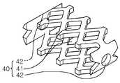
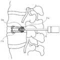
이와 같은 방식으로 척추융합 하는 종래의 척추융합 시술용 이식구(40)는 도 1에 나타낸 바와 같이 상호 대향하는 양쪽이 관통되고 둘레를 따라가면서 일정하게 구멍(41)이 형성되어 있는 연속형 띠 형태로 이루어져 있으며, 선단과 후단에는 각각 척추융합 이식구(40)을 삽입하거나 90°회전시키기 위해 시술 드라이버를 연결하거나 뼈 재료나 융합 촉진 재료를 투입하기 위한 홀(42)이 형성되어 있다. 특히, 상기 척추융합 이식구(40)의 선단부는 후단부 보다 좌우 폭이 넓게 되어 있어서, 이식 완료 후 인접하는 추체 사이의 앞뒤 간격에 알맞게 삽입되어 자리를 잡을 수 있게 된다.The conventional spinal fusion procedure implant 40 for spinal fusion in this manner is a continuous band form in which
이와 같은 종래의 척추융합 시술용 이식구(40)는 인접하는 추체 사이의 앞뒤 간격에 맞게 선단의 좌우 폭을 후단 보다 크게 제작됨으로서 눕혀서 삽입한 후, 90°회전시키게 되면 돌출된 양쪽 가장자리에 의해 불필요하게 뼈가 많이 깎기면서 정상적인 뼈에 손상을 입게되는 문제점이 있으며, 이로 인해 뼈의 융합기간이 상당히 지연되는 등 환자에게 많은 부담을 주는 문제점이 있다.Such a conventional spinal
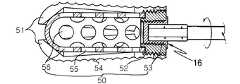
그리고, 도 2의 척추융합 시술용 이식구(50)의 경우에는 선단부가 확장 가능한 원통형의 이식구본체(51)와, 그 이식구본체의 선단부 확장을 가능하게 하는 이식구가압체(56)와, 상기 이식구본체의 내측으로 체결되면서 이식구가압체를 밀어주는 이식구체결체(52)와, 상기 이식구본체의 후부에 조합되면서 그 후부를 마감하는 캡(53)을 포함하는 구성으로 되어 있으며, 상기 이식구본체의 표면은 길이방향을 따라 연속되는 물결무늬의 요철(54)과 다수의 구멍(55)이 형성되고, 상기 이식구가압체에도 다수의 구멍(57)이 형성되어 있다.And, in the case of the spinal
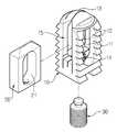
또, 도 3의 척추융합 시술용 이식구(60)의 경우에는 후단부의 핀 결합부위를 통해 서로 마주보면서 나란하게 조합되며 선단부를 이용하여 확장 가능한 한쌍의 이식구본체(60)와, 중심을 관통하는 나사구멍(61)을 갖고 있으며 상기 이식구본체의 후단부 핀 결합부위를 지지하는 이식구지지체(62)와, 상기 이식물지지체의 나사구멍에 체결되며 이식구본체의 선단부 확장을 위한 체결력을 제공하는 이식구체결체(63)와, 상기 이식구체결체 및 한쌍의 이식구본체와 각각 연결되며 이식구체결체로부터 체결력을 제공받아 한쌍의 이식구본체를 바깥쪽으로 벌려주는 링크부재(64)를 포함하는 구성으로 이루어진다.In addition, in the case of the spinal
이상의 도 2 및 도 3에 나타낸 척추융합 시술용 이식구(50),(60)는 구조가 너무 복잡하고 난해하여 제작상의 어려움과 제조단가가 높아지는 문제점이 있고, 또 그 이식구본체(51)(60)의 내부에 이식구가압체(56)와, 링크부재(64)가 삽입 장착되 기 때문에 그로 인한 이식구본체(51)(60)의 내부 공간이 협소하여 척추융합 시술 후 뼈와의 융합 촉진을 위하여 충입되는 융합촉진제를 충분히 충입하지 못하는 문제점이 발생하였다. 따라서, 뼈의 융합기간이 상당히 지연되는 등 환자에게 많은 부담을 주는 문제점이 있었다.The
본 발명은 상기와 같은 제반 문제점을 감안하여 이를 해소하고자 발명한 것으로서, 그 목적은 첫째, 척추융합 시술용 이식구의 구조를 간단하게 하여 종래 복잡한 구조에 따른 제작상의 어려움과 제조단가가 높아지는 문제점을 해소하고, 둘째, 이식구본체의 확장폭을 극대화 시켰으며, 셋째, 이식구본체의 내부 공간을 최대한 확보하여 척추융합 시술 후 뼈와의 융합 촉진을 위하여 충입되는 융합촉진제를 충분히 충입할 수 있도록 함으로서 시술을 받은 환자의 뼈 융합기간을 단축하고, 그에 따른 환자의 부담을 감소시켜 주도록 하는 척추융합 시술용 이식구를 제공함에 있다.
The present invention has been made to solve the above problems in view of the above problems, the object of the first is to simplify the structure of the implant for spinal fusion procedure to solve the problems of manufacturing difficulties and manufacturing cost according to the conventional complex structure increases And secondly, maximizing the expansion of the graft body, and thirdly, securing the internal space of the graft body as much as possible to sufficiently fill the fusion accelerator filled to promote the fusion with bone after spinal fusion procedure. The present invention provides a spinal fusion implant that can shorten the bone fusion period of a patient and thereby reduce the burden on the patient.
상기 목적을 달성하기 위한 본 발명의 척추융합 시술용 이식구 구성은, 외주 면에 요철이 형성되고 양측 상호 마주보는 면은 상호 통하는 관통부가 형성되며 상기 관통부가 형성된 측면에는 상호 관통되는 삽입홀이 형성되고 상부에서부터 하부 일부에 이르기까지는 절개선이 연이어지게 형성된 이식구본체와;In the spinal fusion procedure graft configuration of the present invention for achieving the above object, irregularities are formed on the outer circumferential surface and the sides facing each other are formed through the through-hole and the insertion hole is formed through the side formed with the through-hole A graft main body formed in succession from the top to the lower part;
상기 이식구본체의 후단 면 중앙과 상기 관통부의 하단 중앙부를 관통하는 볼트체결공과;A bolt fastening hole penetrating a center of a rear end surface of the implantation port body and a lower center portion of the penetrating portion;
상기 이식구본체의 외부로 돌출되지 않도록 상기 삽입홀에 삽입 장착되며 상기 이식구본체에 형성된 관통부와 동일한 크기 및 형상의 관통부가 형성된 이식구본체 확장구와;A graft main body expansion tool inserted into the insertion hole so as not to protrude out of the graft main body, and having a penetration part having the same size and shape as the through part formed in the graft main body;
상기 이식구본체 확장구의 하단부와 관통되게 연결 설치되고 상기 볼트체결공에 결합되어 필요에 따라 상기 이식구본체 확장구를 이동시켜 이식구본체를 절개선을 중심으로 확장시켜주는 볼트를 포함하는 구성으로 이루어진다.It is installed to be connected to the lower end of the graft main body expansion port and coupled to the bolt fastening hole to move the graft main body extension as necessary to include a configuration that includes a bolt to expand the center of the incision line around the incision line Is done.
그리고, 상기 외주 면에 요철이 형성된 이식구본체의 형상은, 상부가 호형인 육면체의 4각기둥 형태이고, 상기 이식구본체의 외주 면에 형성된 요철은, 관통부가 형성된 해당 면만 형성되고, 그 요철의 형태는 톱니형태이며, 상기 이식구본체에 형성된 절개선의 절개 범위는, 관통부의 최 하단보다 더 길게 연장 형성시켜 된 것이다.In addition, the shape of the implanted main body having the irregularities formed on the outer circumferential surface is in the form of a tetrahedron of an arc-shaped hexahedron whose upper part is an arc, and the irregularities formed on the outer circumferential surface of the implanted main body have only a corresponding surface having a penetration formed thereon The form is sawtooth-shaped, and the cutting range of the incision line formed in the graft main body is formed to extend longer than the lowest end of the penetrating portion.
또, 상기 외주 면에 요철이 형성된 이식구본체의 형상은, 상면이 호형인 원기둥 형태이고, 상기 원기둥형의 이식구본체에 형성된 요철은, 상면과 하면 및 관통부를 제외한 원주면 전체에 성형된 것이고, 그 원주면 전체에 형성된 요철은 돌출 띠가 일정간격으로 형성된 것임, 상기 척추융합 시술용 이식구의 재질은, 코발트, 크롬, 스테인레스, 티탄, 플라스틱, 세라믹 중 어느 선택된 것이다.In addition, the shape of the implanted main body having the irregularities formed on the outer circumferential surface is a cylindrical shape having an upper surface arc-shaped, and the irregularities formed on the cylindrical shaped implanted main body are formed on the entire circumferential surface except the upper surface, the lower surface, and the penetrating portion. , The unevenness formed on the entire circumferential surface is a protruding band is formed at regular intervals, the material of the implant for spinal fusion procedure is selected from cobalt, chromium, stainless steel, titanium, plastic, ceramic.
상기와 같은 구성으로 이루어진 척추융합 시술용 이식구를 첨부도면을 참조하여 상세하게 설명하면 다음과 같다.When described in detail with reference to the accompanying drawings, the implant for spinal fusion procedure consisting of the above configuration as follows.
본 발명의 도면 도 4 및 도 5는 본 발명 제1실시예의 척추융합 시술용 이식구 사시도이고, 도 5는 본 발명 제1실시예의 척추융합 시술용 이식구 분해 사시도로서, 이에 나타낸 바와 같이 척추융합 시술용 이식구본체(10)는 외주 면에 요철(12)이 형성되고 양측 상호 마주보는 면은 상호 통하는 관통부(11)가 형성되며 그 관통부(11)가 형성된 면의 타측 양면 중앙에는 상부에서부터 하부 일부에 이르기까지 연이어지는 절개선(13)이 형성되어 있다.4 and 5 are a perspective view of the implant for spinal fusion procedure of the first embodiment of the present invention, Figure 5 is an exploded perspective view of the implant for spinal fusion procedure of the first embodiment of the present invention, as shown in the spinal fusion The implanted graft
이와 같이 형성된 상기 이식구본체(10)의 외관 형상은 직육면체 즉 4각 기둥형태로 되어 있으며, 그 직육면체 즉 4각 기둥형태로 되어 있는 이식구본체(10)의 상면은 호형으로 형성시켰는데, 그 이유는, 척추시술을 하고자 뼈 사이에 이식구본체(10)를 삽입할 때에 그 삽입을 용이하게 하기 위함이다.The external shape of the implanted
또, 상기 이식구본체(10)의 관통부(11)는 양 측면의 상호 마주보는 면에 상호 통하도록 형성되는데, 그 이유는, 척추융합 시술 후 뼈와의 융합 촉진을 위하여 충입되는 융합촉진제를 충분히 충입할 수 있는 공간을 확보할 수 있고 그와 아울러 뼈의 내부성장에 따른 그 뼈의 결합을 도와주는 역할을 하기 위하여 공간을 최대로 확보하는 것이 바람직하다.In addition, the penetrating
또한, 상기 관통부(11)가 형성된 양 측면의 가장자리에는 톱니형태의 요철(12)이 형성되어 있는데, 그 요철(12)을 형성시킨 이유는, 척추시술을 하고자 뼈 사이에 이식구본체(10)를 삽입했을 때 그 삽입된 이식구본체(10)가 뼈 사이에서 위치이동하지 않고 안전하게 고정되게 하기 위하여 형성시킨 것이다.In addition, the sawtooth concave-
한편, 상기 요철(12)이 형성된 면의 측면 즉 나머지 양면에는 삽입홀(15)이 상 호 관통되게 형성되어 있는데, 그 삽입홀(15)은 이식구본체 확장구(20)를 수용하도록 형성되어 있고 이에 이식구본체 확장구(20)를 삽입하면 안전하고 견고한 결합이 이루어지는 것이다.On the other hand, the side of the surface on which the
단, 상기 이식구본체 확장구(20)의 양 외곽 폭 및 형상은 이식구본체(10)의 양 외곽 폭 및 형상과 동일하게 형성되어 있기 때문에 이식구본체(10)의 삽입홀(15)에 이식구본체 확장구(20)를 삽입하면 상기 이식구본체(10)의 형상인 직육면체 즉 4각 기둥형태를 해치지 않는다.However, since both outer widths and shapes of the graft main
그리고, 상기 이식구본체 확장구(20)에 형성된 관통부(21)와 이식구본체(10)에 형성된 관통부(11)는 그 크기 및 형상이 동일하기 때문에 상기 이식구본체(10)에 이식구본체 확장구(20)를 결합하면 관통부(11)(21)는 상호 일치한다.In addition, the penetrating
또한, 상기 이식구본체(10)에 형성된 절개선(13)은 상기 호형면의 중앙과 삽입홀(15)의 양 가상선을 따라 이식구본체(10)의 하부 몸체 일부에 이르기까지 연장 형성되는데, 그 이유는 이식구본체(10)의 확장 량을 최대로 확보하기 위함이다.In addition, the
또, 상기 이식구본체(10)의 저면 중앙과 관통부(11)의 하면 중앙부간에는 볼트체결공(14)을 관통 형성시켜 이에 볼트(30)를 나사결합 하도록 되어 있으며 상기 볼트(30)의 선단은 상기 이식구본체 확장구(20)의 끝단을 관통하며 연결 설치된다. 따라서, 볼트(30)를 회전시키면 이식구본체 확장구(20)는 관통부(11) 내에서 전후하면서 이식구본체(10)의 절개선(13)을 중심으로 확장하게 되는 것이다.In addition, a
단, 상기 볼트(30)의 후단에는 시술용 드라이버를 결합할 수 있도록 홈(31)이 형성되어 있어 이에 상기 시술용 드라이버를 결합한 후 볼트(30)를 회전시킨다.However, a
상술한 바와 같은 본 발명 제1실시예의 척추융합 시술용 이식구를 도 6a 및 도 6b를 참조하여 작용을 설명하면 다음과 같다.Referring to Figure 6a and 6b the operation of the spinal fusion procedure of the first embodiment of the present invention as described above is as follows.
먼저 도 6a에 나타낸 바와 같이 이식구본체(10)의 삽입홀(15)에 이식구본체 확장구(20)를 삽입하고 볼트체결공(14)에 볼트(30)를 결합한 후 그를 척수의 해당 뼈와 뼈 사이 즉 인접된 추세사이에 삽입한다. 그리고, 시술용 드라이버(B)를 홈(31)에 끼운 다음 상기 볼트(30)를 회전시키게 되면 그 회전되는 볼트(30)는 도 6b에 나타낸 바와 같이 전진하면서 이식구본체(10)를 확장시키게 되는데, 그 확장은 절개선(13)을 중심으로 이식구본체(10)가 전방에서부터 양분되면서 확장이 이루어지게 된다.First, as shown in FIG. 6A, the implant
상기와 같이 이식구본체(10)가 양분되면서 확장이 이루어지면 도 7에 나타낸 바와 같이 척수의 해당 뼈와 뼈 사이 즉 인접하는 추세 사이가 원하고자하는 만큼 이격된 상태로 자리를 잡게되고, 이의 과정이 완료되면 상기 시술용 드라이버(B)를 볼트(30)의 홈(31)으로부터 분리한 후 관통부(11),(21)에 뼈의 융합촉진제(골 전도성, 골 유도성, 골 형성재료)를 충분히 충입하면 척수시술이 완료되는 것이다.As described above, when the graft
이상의 설명은 본 발명 제1실시예의 척추융합 시술용 이식구에 대한 것이고, 이하의 설명은 본 발명 제2실시예의 척추융합 시술용 이식구에 대한 것이다.The above description is for the spinal fusion procedure graft of the first embodiment of the present invention, the following description is for the spinal fusion procedure graft of the second embodiment of the present invention.
본 발명의 도면 도 8은 본 발명 제2실시예의 척추융합 시술용 이식구 사시도이고, 도 9는 본 발명 제1실시예의 척추융합 시술용 이식구 분해 사시도로서, 이에 나타낸 바와 같이 척추융합 시술용 이식구본체(10a)는 외주 면에 요철(12a)이 형성되고 양측 상호 마주보는 면은 상호 통하는 관통부(11a)가 형성되며 그 관통부(11a)가 형성된 면의 타측 양면 중앙에는 상부에서부터 하부 일부에 이르기까지 연이어지는 절개선(13a)이 형성되어 있다.Figure 8 is a perspective view of the implant port for spinal fusion procedure of the second embodiment of the present invention, Figure 9 is an exploded perspective view of the implant port for spinal fusion procedure of the first embodiment of the present invention, as shown here The
이와 같이 형성된 상기 이식구본체(10a)의 외관 형상은 원기둥형태로 되어 있으며, 그 원기둥형태로 되어 있는 이식구본체(10a)의 상면은 호형으로 형성시켰는데, 그 이유는, 척추시술을 하고자 뼈 사이에 이식구본체(10a)를 삽입할 때에 그 삽입을 용이하게 하기 위함이다.The appearance of the transplanted
또, 상기 이식구본체(10a)의 관통부(11a)는 양 측면의 상호 마주보는 면에 상호 통하도록 형성되는데, 그 이유는, 척추융합 시술 후 뼈와의 융합 촉진을 위하여 충입되는 융합촉진제를 충분히 충입할 수 있는 공간을 확보할 수 있고 그와 아울러 뼈의 내부성장에 따른 그 뼈의 결합을 도와주는 역할을 하기 위하여 공간을 최대로 확보하는 것이 바람직하다.In addition, the penetrating portion (11a) of the graft main body (10a) is formed so as to communicate with each other on the mutually opposite sides, the reason is, the fusion accelerator filled for promoting fusion with bone after spinal fusion procedure It is desirable to secure the space to the maximum in order to secure a space that can be sufficiently filled and also to help the bonding of the bone according to the internal growth of the bone.
또한, 상기 관통부(11a)가 형성된 양 측면의 가장자리에는 돌출 띠 형태의 요철(12a)이 일정간격으로 형성되어 있는데, 그 요철(12a)을 형성시킨 이유는, 척추시술을 하고자 뼈 사이에 이식구본체(10a)를 삽입했을 때 그 삽입된 이식구본체(10a)가 뼈 사이에서 위치이동하지 않고 안전하게 고정되게 하기 위하여 형성시킨 것이다.In addition, protruding strip-shaped
한편, 상기 요철(12a)이 형성된 면의 측면 즉 나머지 양면에는 삽입홀(15a)이 상호 관통되게 형성되어 있는데, 그 삽입홀(15a)은 이식구본체 확장구(20a)를 수용하도록 형성되어 있고 이에 이식구본체 확장구(20a)를 삽입하면 안전하고 견고한 결합이 이루어지는 것이다.On the other hand, the insertion hole (15a) is formed to penetrate each other on the side surface of the surface on which the uneven (12a) is formed, the other both sides, the insertion hole (15a) is formed to accommodate the implant body expansion opening (20a) Inserting the implant extension body (20a) is a safe and secure coupling is made.
단, 상기 이식구본체 확장구(20a)의 양 외곽 폭 및 형상은 이식구본체(10a)의 양 외곽 폭 및 형상과 동일하게 형성되어 있기 때문에 이식구본체(10a)의 삽입홀(15a)에 이식구본체 확장구(20a)를 삽입하면 상기 이식구본체(10a)의 형상인 원기둥형태를 해치지 않는다.However, since both outer widths and shapes of the graft main
그리고, 상기 이식구본체 확장구(20a)에 형성된 관통부(21a)와 이식구본체(10a)에 형성된 관통부(11a)는 그 크기 및 형상이 동일하기 때문에 상기 이식구본체(10a)에 이식구본체 확장구(20a)를 결합하면 관통부(11a)(21a)는 상호 일치한다.In addition, the penetrating
또한, 상기 이식구본체(10a)에 형성된 절개선(13a)은 상기 호형면의 중앙과 삽입홀(15a) 및 관통부(11a)의 양 가상선을 따라 이식구본체(10a)의 하부 몸체 일부에 이르기까지 연장 형성되는데, 그 이유는 이식구본체(10a)의 확장 량을 최대로 확보하기 위함이다.In addition, the
또, 상기 이식구본체(10a)의 저면 중앙과 관통부(11a)의 하면 중앙부간에는 볼트체결공(14a)을 관통 형성시켜 이에 볼트(30a)를 나사결합 하도록 되어 있으며 상기 볼트(30)의 선단은 상기 이식구본체 확장구(20a)의 끝단을 관통하며 연결 설치된다. 따라서, 볼트(30a)를 회전시키면 이식구본체 확장구(20a)는 관통부(11) 내에서 전후하면서 이식구본체(10a)의 절개선(13a)을 중심으로 확장하게 되는 것이다.In addition, a
단, 상기 볼트(30a)의 후단에는 시술용 드라이버(B)를 결합할 수 있도록 홈(31a)이 형성되어 있어 이에 상기 시술용 드라이버를 결합한 후 볼트(30a)를 회전시킨다.However, a
상술한 바와 같은 본 발명 제2실시예의 척추융합 시술용 이식구를 도 10a 및 도 10b를 참조하여 작용을 설명하면 다음과 같다.The operation of the spinal fusion procedure implantation of the second embodiment of the present invention as described above with reference to FIGS. 10A and 10B is as follows.
먼저 도 10a에 나타낸 바와 같이 이식구본체(10a)의 삽입홀(15a)에 이식구본체 확장구(20a)를 삽입하고 볼트체결공(14a)에 볼트(30a)를 결합한 후 그를 척수의 해당 뼈와 뼈 사이 즉 인접된 추세사이에 삽입한다. 그리고, 시술용 드라이버(B)를 홈(31a)에 끼운 다음 상기 볼트(30a)를 회전시키게 되면 그 회전되는 볼트(30a)는 도 10b에 나타낸 바와 같이 전진하면서 이식구본체(10a)를 확장시키게 되는데, 그 확장은 절개선(13a)을 중심으로 이식구본체(10a)가 전방에서부터 4분되면서 확장이 이루어지게 된다.First, as shown in FIG. 10A, the implantation port
상기와 같이 이식구본체(10a)가 4분되면서 확장이 이루어지면 도 11에 나타낸 바와 같이 척수의 해당 뼈와 뼈 사이 즉 인접하는 추세 사이가 원하고자하는 만큼 이격된 상태로 자리를 잡게되고, 이의 과정이 완료되면 상기 시술용 드라이버(B)를 볼트(30a)의 홈(31a)으로부터 분리한 후 관통부(11a),(21a)에 뼈의 융합촉진제(골 전도성, 골 유도성, 골 형성재료)를 충분히 충입하면 척수시술이 완료되는 것이다.As described above, when the graft
이상의 본 발명 제1 및 제2 실시예의 척추융합 시술용 이식구는 코발트, 크롬, 스테인레스, 티탄, 플라스틱, 세라믹 등과 같은 인체이식에 적합한 재질로 제조되며, 관통부 내부에는 수산화연화석 또는 임의의 다른 골전도성, 골유도성, 골 형성재료 또는 다른 융합형성재료 등과 같은 뼈 성장유도재료가 채워지거나 피복 될 수 있다.The implant for spinal fusion procedure of the first and second embodiments of the present invention is made of a material suitable for human transplantation, such as cobalt, chromium, stainless steel, titanium, plastic, ceramics, etc. Bone growth inducing materials, such as conductive, osteoinductive, bone forming materials or other fusion forming materials, may be filled or coated.
상술한 바와 같은 본 발명의 척추융합 시술용 이식구는, 첫째, 이식구본체의 확장 량을 최대로 확보하기 위하여 절개선을 연장 형성시켰고, 둘째, 뼈의 성장 및 뼈 융합촉진제를 채울 수 있도록 내부공간을 최대한 확보함으로서, 뼈가 안정적이고 신속하게 융합될 수 있게 하고, 시술 후 뼈의 성장과 안전성을 향상시킬 수 있게 하며, 궁극적으로 환자에게는 시술 후 뼈의 성장과 안전성을 향상시키는데 도움을 줌은 물론, 의사에게는 시술의 용이함에 따른 심리적 안정감을 부여하여 척추 융합 시술이 전반적으로 안전하고 효율적으로 진행될 수 있게 한 효과가 있다.The implantation device for spinal fusion procedure of the present invention as described above, firstly, in order to secure the maximum amount of expansion of the graft main body, the incision is extended, and second, the internal space to fill the bone growth and bone fusion promoter To ensure maximum stability and rapid fusion of bones, improve bone growth and safety after the procedure, and ultimately help patients improve bone growth and safety after the procedure. In addition, the doctor has a psychological stability according to the ease of the procedure to have the effect that the spinal fusion procedure can proceed safely and efficiently.
Claims (7)
Translated fromKoreanPriority Applications (1)
| Application Number | Priority Date | Filing Date | Title |
|---|---|---|---|
| KR1020030095958AKR100578710B1 (en) | 2003-12-24 | 2003-12-24 | Spinal Fusion Procedure |
Applications Claiming Priority (1)
| Application Number | Priority Date | Filing Date | Title |
|---|---|---|---|
| KR1020030095958AKR100578710B1 (en) | 2003-12-24 | 2003-12-24 | Spinal Fusion Procedure |
Publications (2)
| Publication Number | Publication Date |
|---|---|
| KR20050064501A KR20050064501A (en) | 2005-06-29 |
| KR100578710B1true KR100578710B1 (en) | 2006-05-12 |
Family
ID=37256094
Family Applications (1)
| Application Number | Title | Priority Date | Filing Date |
|---|---|---|---|
| KR1020030095958AExpired - LifetimeKR100578710B1 (en) | 2003-12-24 | 2003-12-24 | Spinal Fusion Procedure |
Country Status (1)
| Country | Link |
|---|---|
| KR (1) | KR100578710B1 (en) |
Cited By (1)
| Publication number | Priority date | Publication date | Assignee | Title |
|---|---|---|---|---|
| KR20210117019A (en)* | 2020-03-18 | 2021-09-28 | 주식회사 엔닥 | Cage for minimal invasive surgery |
Families Citing this family (10)
| Publication number | Priority date | Publication date | Assignee | Title |
|---|---|---|---|---|
| KR100834955B1 (en)* | 2006-11-09 | 2008-06-03 | 이부락 | Method and composition for preparing chiropractic device consisting of two kinds of physical properties |
| US8906028B2 (en) | 2009-09-18 | 2014-12-09 | Spinal Surgical Strategies, Llc | Bone graft delivery device and method of using the same |
| US10245159B1 (en) | 2009-09-18 | 2019-04-02 | Spinal Surgical Strategies, Llc | Bone graft delivery system and method for using same |
| US10973656B2 (en) | 2009-09-18 | 2021-04-13 | Spinal Surgical Strategies, Inc. | Bone graft delivery system and method for using same |
| US9445919B2 (en)* | 2011-12-19 | 2016-09-20 | Warsaw Orthopedic, Inc. | Expandable interbody implant and methods of use |
| KR101352820B1 (en)* | 2012-01-11 | 2014-01-17 | 주식회사 디오메디칼 | A lumbar expandable cage |
| US9788971B1 (en) | 2013-05-22 | 2017-10-17 | Nuvasive, Inc. | Expandable fusion implant and related methods |
| US9801734B1 (en) | 2013-08-09 | 2017-10-31 | Nuvasive, Inc. | Lordotic expandable interbody implant |
| KR101502061B1 (en)* | 2013-10-02 | 2015-03-11 | (주) 서한케어 | Expandable fusion cage |
| KR20220084881A (en) | 2020-12-14 | 2022-06-21 | (주) 서한케어 | Expandable cage for intervertebral body |
- 2003
- 2003-12-24KRKR1020030095958Apatent/KR100578710B1/ennot_activeExpired - Lifetime
Cited By (2)
| Publication number | Priority date | Publication date | Assignee | Title |
|---|---|---|---|---|
| KR20210117019A (en)* | 2020-03-18 | 2021-09-28 | 주식회사 엔닥 | Cage for minimal invasive surgery |
| KR102379915B1 (en)* | 2020-03-18 | 2022-03-29 | 주식회사 엔닥 | Cage for minimal invasive surgery |
Also Published As
| Publication number | Publication date |
|---|---|
| KR20050064501A (en) | 2005-06-29 |
Similar Documents
| Publication | Publication Date | Title |
|---|---|---|
| US9320549B2 (en) | Spinal fixation plates | |
| US5861041A (en) | Intervertebral disk prosthesis and method of making the same | |
| US6179874B1 (en) | Articulating spinal implant | |
| US7935136B2 (en) | Facet joint fusion devices and methods | |
| AU721404B2 (en) | Expandable non-threaded spinal fusion device | |
| AU778600B2 (en) | Articulating spinal implant | |
| EP2446843B1 (en) | Interspinous spacer assembly | |
| JP2008054710A (en) | Transplantation implement for spinal fusion surgery | |
| JP2003501142A (en) | Artificial implant for intervertebral disc | |
| WO1998044877A9 (en) | Intervertebral disk prosthesis and method of making the same | |
| KR100578710B1 (en) | Spinal Fusion Procedure | |
| US10695188B2 (en) | Artificial epistropheus support body | |
| JP2003000623A (en) | Spinal fusionable implant | |
| CN201108492Y (en) | A kind of atlantoaxial intervertebral joint fusion device | |
| CN213607208U (en) | Expansion type interbody fusion cage applied to minimally invasive spine surgery | |
| KR102560914B1 (en) | Cervical cage set with rotatable plate | |
| CN105055058A (en) | Artificial vertebral lamina and vertebral canal expansion tool | |
| US8123811B2 (en) | Cervical implant | |
| KR100395253B1 (en) | Backbone fused implant | |
| KR100395252B1 (en) | Backbone fused implant | |
| CN201572171U (en) | Spinous process opening device | |
| KR200216158Y1 (en) | Backbone fused implant | |
| US20250073043A1 (en) | Internal fixation device for fusion and reconstruction of spinous processes and vertebral laminae | |
| KR100526359B1 (en) | cage for fixing in vertebra of human | |
| KR101009937B1 (en) | Intervertebral Implants |
Legal Events
| Date | Code | Title | Description |
|---|---|---|---|
| A201 | Request for examination | ||
| PA0109 | Patent application | St.27 status event code:A-0-1-A10-A12-nap-PA0109 | |
| PA0201 | Request for examination | St.27 status event code:A-1-2-D10-D11-exm-PA0201 | |
| PG1501 | Laying open of application | St.27 status event code:A-1-1-Q10-Q12-nap-PG1501 | |
| D13-X000 | Search requested | St.27 status event code:A-1-2-D10-D13-srh-X000 | |
| D14-X000 | Search report completed | St.27 status event code:A-1-2-D10-D14-srh-X000 | |
| E902 | Notification of reason for refusal | ||
| PE0902 | Notice of grounds for rejection | St.27 status event code:A-1-2-D10-D21-exm-PE0902 | |
| P11-X000 | Amendment of application requested | St.27 status event code:A-2-2-P10-P11-nap-X000 | |
| P13-X000 | Application amended | St.27 status event code:A-2-2-P10-P13-nap-X000 | |
| E701 | Decision to grant or registration of patent right | ||
| PE0701 | Decision of registration | St.27 status event code:A-1-2-D10-D22-exm-PE0701 | |
| GRNT | Written decision to grant | ||
| PR0701 | Registration of establishment | St.27 status event code:A-2-4-F10-F11-exm-PR0701 | |
| PR1002 | Payment of registration fee | St.27 status event code:A-2-2-U10-U11-oth-PR1002 Fee payment year number:1 | |
| PG1601 | Publication of registration | St.27 status event code:A-4-4-Q10-Q13-nap-PG1601 | |
| PR1001 | Payment of annual fee | St.27 status event code:A-4-4-U10-U11-oth-PR1001 Fee payment year number:4 | |
| PR1001 | Payment of annual fee | St.27 status event code:A-4-4-U10-U11-oth-PR1001 Fee payment year number:5 | |
| PR1001 | Payment of annual fee | St.27 status event code:A-4-4-U10-U11-oth-PR1001 Fee payment year number:6 | |
| R18-X000 | Changes to party contact information recorded | St.27 status event code:A-5-5-R10-R18-oth-X000 | |
| PR1001 | Payment of annual fee | St.27 status event code:A-4-4-U10-U11-oth-PR1001 Fee payment year number:7 | |
| FPAY | Annual fee payment | Payment date:20130327 Year of fee payment:8 | |
| PR1001 | Payment of annual fee | St.27 status event code:A-4-4-U10-U11-oth-PR1001 Fee payment year number:8 | |
| FPAY | Annual fee payment | Payment date:20140507 Year of fee payment:9 | |
| PR1001 | Payment of annual fee | St.27 status event code:A-4-4-U10-U11-oth-PR1001 Fee payment year number:9 | |
| FPAY | Annual fee payment | Payment date:20150529 Year of fee payment:10 | |
| PR1001 | Payment of annual fee | St.27 status event code:A-4-4-U10-U11-oth-PR1001 Fee payment year number:10 | |
| PN2301 | Change of applicant | St.27 status event code:A-5-5-R10-R13-asn-PN2301 St.27 status event code:A-5-5-R10-R11-asn-PN2301 | |
| PC1903 | Unpaid annual fee | St.27 status event code:A-4-4-U10-U13-oth-PC1903 Not in force date:20160505 Payment event data comment text:Termination Category : DEFAULT_OF_REGISTRATION_FEE | |
| FPAY | Annual fee payment | Payment date:20170124 Year of fee payment:11 | |
| K11-X000 | Ip right revival requested | St.27 status event code:A-6-4-K10-K11-oth-X000 | |
| PC1903 | Unpaid annual fee | St.27 status event code:N-4-6-H10-H13-oth-PC1903 Ip right cessation event data comment text:Termination Category : DEFAULT_OF_REGISTRATION_FEE Not in force date:20160505 | |
| PR0401 | Registration of restoration | St.27 status event code:A-6-4-K10-K13-oth-PR0401 | |
| PR1001 | Payment of annual fee | St.27 status event code:A-4-4-U10-U11-oth-PR1001 Fee payment year number:11 | |
| R401 | Registration of restoration | ||
| FPAY | Annual fee payment | Payment date:20170327 Year of fee payment:12 | |
| PR1001 | Payment of annual fee | St.27 status event code:A-4-4-U10-U11-oth-PR1001 Fee payment year number:12 | |
| P22-X000 | Classification modified | St.27 status event code:A-4-4-P10-P22-nap-X000 | |
| FPAY | Annual fee payment | Payment date:20180918 Year of fee payment:13 | |
| PR1001 | Payment of annual fee | St.27 status event code:A-4-4-U10-U11-oth-PR1001 Fee payment year number:13 | |
| FPAY | Annual fee payment | Payment date:20190530 Year of fee payment:14 | |
| PR1001 | Payment of annual fee | St.27 status event code:A-4-4-U10-U11-oth-PR1001 Fee payment year number:14 | |
| PR1001 | Payment of annual fee | St.27 status event code:A-4-4-U10-U11-oth-PR1001 Fee payment year number:15 | |
| P14-X000 | Amendment of ip right document requested | St.27 status event code:A-5-5-P10-P14-nap-X000 | |
| PR1001 | Payment of annual fee | St.27 status event code:A-4-4-U10-U11-oth-PR1001 Fee payment year number:16 | |
| PR1001 | Payment of annual fee | St.27 status event code:A-4-4-U10-U11-oth-PR1001 Fee payment year number:17 | |
| PR1001 | Payment of annual fee | St.27 status event code:A-4-4-U10-U11-oth-PR1001 Fee payment year number:18 | |
| PC1801 | Expiration of term | St.27 status event code:N-4-6-H10-H14-oth-PC1801 Not in force date:20231225 Ip right cessation event data comment text:Termination Category : EXPIRATION_OF_DURATION |