KR100577056B1 - Multiple concurrent access - Google Patents
Multiple concurrent accessDownload PDFInfo
- Publication number
- KR100577056B1 KR100577056B1KR1020047017984AKR20047017984AKR100577056B1KR 100577056 B1KR100577056 B1KR 100577056B1KR 1020047017984 AKR1020047017984 AKR 1020047017984AKR 20047017984 AKR20047017984 AKR 20047017984AKR 100577056 B1KR100577056 B1KR 100577056B1
- Authority
- KR
- South Korea
- Prior art keywords
- page
- contone
- nozzles
- resource
- printhead
- Prior art date
- Legal status (The legal status is an assumption and is not a legal conclusion. Google has not performed a legal analysis and makes no representation as to the accuracy of the status listed.)
- Expired - Fee Related
Links
Images


Classifications
- B—PERFORMING OPERATIONS; TRANSPORTING
- B41—PRINTING; LINING MACHINES; TYPEWRITERS; STAMPS
- B41J—TYPEWRITERS; SELECTIVE PRINTING MECHANISMS, i.e. MECHANISMS PRINTING OTHERWISE THAN FROM A FORME; CORRECTION OF TYPOGRAPHICAL ERRORS
- B41J2/00—Typewriters or selective printing mechanisms characterised by the printing or marking process for which they are designed
- B41J2/005—Typewriters or selective printing mechanisms characterised by the printing or marking process for which they are designed characterised by bringing liquid or particles selectively into contact with a printing material
- B41J2/01—Ink jet
- B41J2/07—Ink jet characterised by jet control
- H—ELECTRICITY
- H04—ELECTRIC COMMUNICATION TECHNIQUE
- H04N—PICTORIAL COMMUNICATION, e.g. TELEVISION
- H04N1/00—Scanning, transmission or reproduction of documents or the like, e.g. facsimile transmission; Details thereof
- H04N1/387—Composing, repositioning or otherwise geometrically modifying originals
- H04N1/3871—Composing, repositioning or otherwise geometrically modifying originals the composed originals being of different kinds, e.g. low- and high-resolution originals
- G—PHYSICS
- G06—COMPUTING OR CALCULATING; COUNTING
- G06K—GRAPHICAL DATA READING; PRESENTATION OF DATA; RECORD CARRIERS; HANDLING RECORD CARRIERS
- G06K15/00—Arrangements for producing a permanent visual presentation of the output data, e.g. computer output printers
- G06K15/02—Arrangements for producing a permanent visual presentation of the output data, e.g. computer output printers using printers
- G06K15/18—Conditioning data for presenting it to the physical printing elements
- G06K15/1801—Input data handling means
- G06K15/181—Receiving print data characterized by its formatting, e.g. particular page description languages
- G06K15/1815—Receiving print data in mixed format
- G—PHYSICS
- G06—COMPUTING OR CALCULATING; COUNTING
- G06K—GRAPHICAL DATA READING; PRESENTATION OF DATA; RECORD CARRIERS; HANDLING RECORD CARRIERS
- G06K15/00—Arrangements for producing a permanent visual presentation of the output data, e.g. computer output printers
- G06K15/02—Arrangements for producing a permanent visual presentation of the output data, e.g. computer output printers using printers
- G06K15/18—Conditioning data for presenting it to the physical printing elements
- G06K15/1848—Generation of the printable image
- G06K15/1852—Generation of the printable image involving combining data of different types
- G—PHYSICS
- G06—COMPUTING OR CALCULATING; COUNTING
- G06K—GRAPHICAL DATA READING; PRESENTATION OF DATA; RECORD CARRIERS; HANDLING RECORD CARRIERS
- G06K15/00—Arrangements for producing a permanent visual presentation of the output data, e.g. computer output printers
- G06K15/02—Arrangements for producing a permanent visual presentation of the output data, e.g. computer output printers using printers
- G06K15/18—Conditioning data for presenting it to the physical printing elements
- G06K15/1848—Generation of the printable image
- G06K15/1856—Generation of the printable image characterized by its workflow
Landscapes
- Engineering & Computer Science (AREA)
- General Engineering & Computer Science (AREA)
- Physics & Mathematics (AREA)
- General Physics & Mathematics (AREA)
- Theoretical Computer Science (AREA)
- Computational Linguistics (AREA)
- Multimedia (AREA)
- Signal Processing (AREA)
- Ink Jet (AREA)
- Facsimile Image Signal Circuits (AREA)
- Image Processing (AREA)
- Color Image Communication Systems (AREA)
- Record Information Processing For Printing (AREA)
- Color, Gradation (AREA)
- Hydrogenated Pyridines (AREA)
- Fixing For Electrophotography (AREA)
- Particle Formation And Scattering Control In Inkjet Printers (AREA)
- Steering Control In Accordance With Driving Conditions (AREA)
- Editing Of Facsimile Originals (AREA)
- Accessory Devices And Overall Control Thereof (AREA)
- Fax Reproducing Arrangements (AREA)
Abstract
Translated fromKoreanDescription
Translated fromKorean도 1은 프린터에서 2중-버퍼링으로써 성취 가능한 지속 인쇄 속도을 예시하는 테이블,1 is a table illustrating sustained print speeds achievable with double-buffering in a printer,
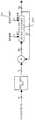
도 2는 애플리케이션으로부터 인쇄된 페이지로의 개념적인 데이터 흐름을 도시하는 흐름도,Fig. 2 is a flow chart showing a conceptual data flow from an application to a printed page;
도 3은 닫힌 구성에서의 아이프린트(iPrint) 프린터의 회화도,3 is a drawing of an iPrint printer in a closed configuration,
도 4는 열린 구성에서의 아이프린트 프린터의 회화도,4 is a drawing diagram of the iPrint printer in an open configuration,
도 5는 프린터를 통하는 용지 통로를 도시하는 절단도,Fig. 5 is a cutaway view showing a paper passage through the printer;
도 6은 멤젯(Memjet) 프린트헤드 카트리지 및 프린트헤드 캡핑(capping) 메카니즘의 절단 회화도,6 is a cut-out drawing of a Memjet printhead cartridge and a printhead capping mechanism;
도 7은 도 6의 멤젯 프린트헤드 카트리지 및 프린트헤드 캡핑 메카니즘의 단면도,Figure 7 is a cross-sectional view of the Memjet printhead cartridge and printhead capping mechanism of Figure 6;
도 8은 프린터 제어기의 회화도,8 is a drawing of the printer controller;
도 9는 단순 블랙 및 화이트 이미지를 코딩하는 예시도,9 is an exemplary diagram for coding a simple black and white image;
도 10은 파이어링 순서로 번호 매겨진 10개의 인쇄 노즐의 파드의 개략도,Figure 10 is a schematic diagram of the pods of ten printing nozzles numbered in firing order;
도 11은 로드 순서로 번호 매겨진 10개의 인쇄 노즐의 동일 파드의 개략도,Fig. 11 is a schematic view of the same pod of ten printing nozzles numbered in load order,
도 12는 크로마파드의 개략도,12 is a schematic diagram of a chromapard,
도 13은 5개의 크로마파드의 파드그룹의 개략도,13 is a schematic diagram of a pod group of five chromapards;
도 14는 2개의 파드그룹의 페이즈그룹의 개략도,14 is a schematic diagram of a phase group of two pod groups;
도 15는 세그먼트, 파이어그룹, 페이즈그룹, 파드그룹 및 크로마파드 사이의 관계를 도시하는 개략도,15 is a schematic diagram showing a relationship between a segment, a fire group, a phase group, a pod group, and a chroma pod;
도 16은 전형적 인쇄 사이클 동안 A이네이블 및 B이네이블 라인의 페이즈도,16 is a phase diagram of the A and B enable lines during a typical print cycle.
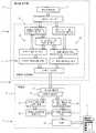
도 17은 프린터 제어기 아키텍처의 도,17 is a diagram of a printer controller architecture;
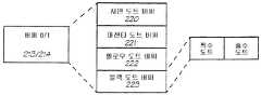
도 18은 페이지 확장 및 인쇄 데이터 흐름을 요약한 흐름도,18 is a flow chart summarizing the page expansion and print data flow;
도 19는 EDRL 확장기 유닛의 블록도,19 is a block diagram of an EDRL expander unit;
도 20은 EDRL 스트림 디코더의 블록도,20 is a block diagram of an EDRL stream decoder;
도 21은 런길이 디코더의 블록도,21 is a block diagram of a runlength decoder;
도 22는 런길이 인코더의 블록도,22 is a block diagram of a runlength encoder;
도 23은 JPEG 디코더의 블록도,23 is a block diagram of a JPEG decoder;
도 24는 하프토너/합성기 유닛의 블록도,24 is a block diagram of a half toner/synthesizer unit;
도 25는 페이지 폭과 여백 사이의 관계를 도시하는 일련의 페이지 라인,Fig. 25 is a series of page lines showing the relationship between page width and margin;
도 26은 다중-임계값 디더의 블록도,26 is a block diagram of a multi-threshold dither;
도 27은 3중-임계값 유닛의 로직의 블록도,Figure 27 is a block diagram of the logic of a triple-threshold unit;
도 28은 프린트헤드 인터페이스의 내부 구조의 블록도,28 is a block diagram of an internal structure of a printhead interface;
도 29는 인쇄 라인 N 및 N+1 동안에 2중 버퍼링의 개념적 개략도,29 is a conceptual schematic diagram of double buffering during printing lines N and N+1,
도 30은 LLFU의 구조의 블록도,30 is a block diagram of the structure of an LLFU;
도 31은 버퍼의 개념적 구조도,31 is a conceptual structure diagram of a buffer;
도 32는 버퍼의 논리적 구조도,32 is a logical structure diagram of a buffer;
도 33은 A이네이블 및 B이네이블 펄스 폭의 발생의 블록도,33 is a block diagram of generation of A enable and B enable pulse widths;
도 34는 도트 카운트 로직의 도,34 is a diagram of dot count logic;
도 35는 스피커 인터페이스의 블록도,35 is a block diagram of a speaker interface;
도 36은 2개-층 페이지 버퍼의 도,36 is a diagram of a two-layer page buffer;
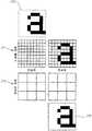
도 37은 화이트 이미지상으로 블랙 대상물의 합성을 도시하는 일련의 도,37 is a series of diagrams showing the synthesis of a black object onto a white image;
도 38은 화이트 이미지상으로 연속톤 대상물의 합성을 도시하는 일련의 도,38 is a series of diagrams showing the synthesis of contone objects onto a white image;
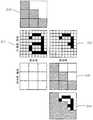
도 39는 연속톤 대상물을 포함하는 이미지상으로 블랙 대상물의 합성을 도시하는 일련의 도,39 is a series of diagrams showing the synthesis of a black object onto an image including a contone object;
도 40은 블랙 대상물을 포함하는 이미지상으로 불투명한 연속톤 대상물의 합성을 도시하는 일련의 도,FIG. 40 is a series of diagrams showing the composition of an opaque continuous-tone object onto an image including a black object;
도 41은 블랙 대상물을 포함하는 이미지상으로 투명한 연속톤 대상물의 합성을 도시하는 일련의 도, 및Fig. 41 is a series of diagrams showing the synthesis of a transparent contone object on an image including a black object, and
도 42는 프린터 드라이버 구성요소를 갖는 윈도우즈 9x/NT 인쇄 시스템의 블록도.Fig. 42 is a block diagram of a Windows 9x/NT printing system with printer driver components.
(기술분야)(Technology field)
본 발명은 페이지-폭 드롭-온-디맨드형 잉크젯 프린트헤드를 사용하는 프린 터와 같은 고성능 컬러 프린터용 프린터 드라이버에 관한 것이다. 또 다른 태양에서, 본 발명은 인쇄 방법에 관한 것이다.The present invention relates to a printer driver for a high-performance color printer, such as a printer using a page-width drop-on-demand type inkjet printhead. In another aspect, the present invention relates to a printing method.
본 발명은 컬러 프린터용 모듈러 프린트헤드에 관한 것이다. 더 나아간 태양에서, 본 발명은 프린트헤드를 사용하여 로딩 및 인쇄하는 방법에 관한 것이다.The present invention relates to a modular printhead for a color printer. In a further aspect, the present invention relates to a method of loading and printing using a printhead.
본 발명은 컬러 프린터용 모듈러 프린트헤드에 관한 것이다. 더 나아간 태양에서, 본 발명은 프린트헤드를 사용하여 로딩 및 인쇄하는 방법에 관한 것이다.The present invention relates to a modular printhead for a color printer. In a further aspect, the present invention relates to a method of loading and printing using a printhead.
본 발명은 전형적으로 페이지-폭 드롭-온-디맨드형 잉크젯 프린트헤드를 사용하는 고성능 컬러 프린터에 관한 것이다. 특히, 본 발명은 연속톤(contone) 컬러 층을 2-레벨로 디지털식으로 하프토닝하고 블랙 층을 하프토닝된 연속톤 층 위로 합성하기 위한 하프토너/합성기 유닛에 관한 것이다. 또 다른 태양에서, 본 발명은 하프토닝 및 합성 방법에 관한 것이다.The present invention relates to a high performance color printer typically using a page-width drop-on-demand inkjet printhead. In particular, the present invention relates to a halftoner/synthesizer unit for digitally halftoning a contone color layer to two levels and synthesizing a black layer onto a halftoned contone layer. In another aspect, the present invention relates to a method of halftoning and synthesis.
본 발명은 연속톤 컬러 화소값의 어레이 형태를 갖는 연속톤 컬러 이미지를 2-레벨 도트로 하프토닝하기 위한 디더 유닛에 관한 것이다. 또 다른 태양에서, 본 발명은 디더 유닛을 동작시키는 방법에 관한 것이다.The present invention relates to a dither unit for halftoning a contone color image having an array of contone color pixel values into two-level dots. In yet another aspect, the present invention relates to a method of operating a dither unit.
본 발명은 프린트헤드용 예열 사이클에 관한 것이다. 본 발명은, 예를 들어, 드롭-온-디맨드형 잉크젯 프린트헤드를 사용하는 고성능 컬러 프린터에서의 유틸리티를 갖는다.The present invention relates to a preheat cycle for a printhead. The present invention has utility in high performance color printers using drop-on-demand inkjet printheads, for example.
본 발명은 컴퓨터 메모리에 유지된 자원 및 그 자원으로의 동시 액세스를 요구하는 다중 병렬 프로세서에 관한 것이다. 자원은 연속톤 컬러 화소값의 어레이 형태를 갖는 연속톤 컬러 이미지를 2-레벨 도트로 디지털식으로 하프토닝하기 위해 사용되는 디더 볼륨 또는 디더 행렬일 수 있고, 이것은 다른 임계 유닛에 의해 병렬로 액세스되도록 요구될 수 있다. 또 다른 태양에서, 본 발명은 그러한 자원에 액세스하는 방법이다.The present invention relates to a resource held in computer memory and to multiple parallel processors requiring simultaneous access to the resource. The resource may be a dither volume or a dither matrix used to digitally halfton a contone color image in the form of an array of contone color pixel values into two-level dots, which can be accessed in parallel by other threshold units. May be required. In another aspect, the present invention is a method of accessing such resources.
본 발명은 프린터용 잉크통의 잉크가 바닥날 때를 예측하기 위한 방법 및 프린터 시스템에 관한 것이다. 프린터는, 예를 들어, 드롭-온-디맨드형 잉크젯 프린트헤드를 사용할 수 있다.The present invention relates to a method and a printer system for predicting when ink in a printer ink container runs out. The printer can use, for example, a drop-on-demand type inkjet printhead.
본 발명은 고성능 컬러 프린터와 같은 프린터용 프린트헤드에서 파이어링(firing) 펄스 지속시간의 제어에 관한 것이다. 본 발명은 특히 제어 시스템 및 방법에 관한 것이다. 프린터는, 예를 들어, 페이지폭 드롭-온-디맨드형 잉크젯 프린트헤드를 사용할 수 있다.The present invention relates to the control of firing pulse duration in a printhead for a printer, such as a high performance color printer. The invention particularly relates to a control system and method. The printer can use, for example, a page width drop-on-demand type inkjet printhead.
(발명의 배경)(Background of the invention)
범용 256-레벨 디더 볼륨은 다른 강도 레벨을 감결합함으로써, 디더 셀 디자인에서 현저한 유연성을 제공한다. 그것은 최적 확률적(stochastic) 디더를 디자인할 때 디더 행렬에 대하여 여분의 자유도를 제공한다[12]. 범용 디더 볼륨은 클 수 있다 - 64×64×256 디더 볼륨은, 예를 들어, 128KB의 크기를 갖는다. 또한 각각의 컬러 구성요소가 볼륨과 다른 비트의 검색을 요구할 수 있기 때문에 그것에 액세스하는 것이 비능률적일 수 있다.The general purpose 256-level dither volume provides significant flexibility in dither cell design by decoupling different intensity levels. It provides extra degrees of freedom for the dither matrix when designing optimal stochastic dither [12]. A general-purpose dither volume can be large-a 64x64x256 dither volume, for example, has a size of 128KB. Also, accessing it can be inefficient because each color component may require searching for a different bit than the volume.
드롭-온-디맨드형 잉크젯 프린트헤드에서, 인쇄된 도트의 크기는 잉크 온도에 따라 변한다. 잉크 방울을 분출하기 위해 에너지가 사용될 때, 잉크 온도가 상승한다. 잉크 방울이 실제로 분출될 때, 그것은 잉크 온도를 다소 가져가 버린다. 다수의 방울을 분출하는 과정 동안 평형 온도에 도달한다. 일단 평형 온도에 도달하면 인쇄 프로세스는 평형 온도에 머무르려는 경향이 강하다.In a drop-on-demand type inkjet printhead, the size of the printed dot changes with the ink temperature. When energy is used to eject ink droplets, the ink temperature rises. When a drop of ink is actually ejected, it takes away the ink temperature somewhat. The equilibrium temperature is reached during the process of ejecting multiple droplets. Once the equilibrium temperature is reached, the printing process has a strong tendency to stay at the equilibrium temperature.
본 발명은 프린트헤드의 온도를 표시하는 신호를 산출하는 온도 센서, 및 잉크통으로부터 잉크를 받는 잉크 공급 포트, 잉크 도트를 분출하는 잉크 증착(deposition) 포트, 및 프린트헤드의 파이어링 사이클 동안에 증착 포트로부터 잉크 도트가 증착되어지게 하는 신호를 수신하는 파이어링 제어 포트를 각각 갖는 복수의 노즐을 포함한 유형의 프린트헤드용 프린트헤드 제어기를 구비한 프린터이다. 여기서, 프린트헤드 제어기는 온도 센서로부터 프린트헤드의 온도를 표시하는 신호를 수신하는 수단, 및 노즐의 파이어링 제어 포트에 파이어링 신호를 공급하는 수단을 포함하고, 프린트헤드 제어기는, 각각의 인쇄 작업 전에, 모든 노즐을 파이어링으로 설정하고, 각각의 노즐에 일련의 짧은 파이어링 펄스를 제공하기 위해 일련의 변형 파이어링 사이클을 실행하도록 동작 가능하고, 프린트헤드의 온도를 표시하는 신호가 동작 평형 온도에 도달했음을 표시할 때까지 각각의 펄스의 지속시간은 방울을 파이어링하기에는 불충분하지만 잉크를 가열시키기에는 충분하다.The present invention provides a temperature sensor that produces a signal indicative of the temperature of the printhead, and an ink supply port that receives ink from the inkwell, an ink deposition port that ejects ink dots, and from the deposition port during the firing cycle of the printhead. A printer with a printhead controller for a type of printhead that includes a plurality of nozzles each having a firing control port to receive a signal for causing ink dots to be deposited. Here, the printhead controller includes means for receiving a signal indicating the temperature of the printhead from the temperature sensor, and means for supplying a firing signal to the firing control port of the nozzle, and the printhead controller comprises: Previously, it was possible to set all nozzles to firing, and to run a series of modified firing cycles to provide a series of short firing pulses to each nozzle, and a signal indicating the temperature of the printhead is operating at equilibrium temperature. The duration of each pulse until it indicates that it has reached is insufficient to fire the droplet, but sufficient to heat the ink.
예열 모드 동안의 피드백이 T센스(Tsense; 아래에 정의됨)에 의해서 제공될 수 있고, 실온보다 높은 약 30℃의 온도에 도달할 때까지 계속된다. 시간 또는 온도는 잉크 구성물에 의존하여 변할 수 있기 때문에, 평형 온도에 도달하는 때에 관하여 온도 정보가 피드백되게 하는 것이 중요하다.Feedback during the preheat mode can be provided by Tsense (defined below) and continues until a temperature of about 30° C. above room temperature is reached. Since the time or temperature can vary depending on the ink composition, it is important to have temperature information fed back about when the equilibrium temperature is reached.
일 예에서, 각각의 노즐에 대해서 약 200 펄스가 요구된다.In one example, about 200 pulses are required for each nozzle.
예열 모드의 지속시간은 약 50 밀리초일 수 있고, 잉크 구성물에 의존한다.The duration of the preheat mode can be about 50 milliseconds and depends on the ink composition.
예열은 데이터가 프린터에 전송되고 있는 동안에 이루어지기 때문에 성능에 영향을 미치지 않는다.Preheating is done while data is being sent to the printer, so it does not affect performance.
예열 사이클은 1을 갖는 모든 노즐로의 단일 로드 사이클(즉, 모든 노즐을 파이어링으로 설정), 및 각각의 노즐로의 많은 짧은 파이어링 펄스를 수반한다. 펄스의 지속시간은 방울을 파이어링하기에는 불충분하지만 잉크를 가열시키기에는 충분해야 한다. 펄스의 지속시간은 프린터에서 사용되는 잉크의 각각에 대해서 변화할 수 있다. 전체적으로 각각의 노즐에 대해서 약 200 펄스가 요구되고, 표준 인쇄 사이클로서 동일 시퀀스에서 사이클링 스루한다.The preheat cycle entails a single load cycle to all nozzles with 1 (ie, setting all nozzles to firing), and many short firing pulses to each nozzle. The duration of the pulse is insufficient to fire the droplet, but it should be sufficient to heat the ink. The duration of the pulse can vary for each of the ink used in the printer. In total, about 200 pulses are required for each nozzle, cycling through in the same sequence as a standard print cycle.
다중 병렬 프로세서는 컴퓨터 메로리에 유지된 자원으로의 동시 액세스를 요구하는 경우에, 몇 가지 방법이 가능하다. 첫번째로, 프로세서가 교대로 자원에 액세스할 수 있지만, 그러나 이것은 프로세서의 성능을 감소시킨다. 두번째로, 다중-포트 메모리가 사용될 수 있고, 세번째로, 전체 자원이 다른 메모리 뱅크에 복제될 수 있지만 이 두가지 옵션은 비용이 많이 든다.If multiple parallel processors require simultaneous access to resources held in the computer memory, several methods are possible. First, the processors can alternately access resources, but this reduces the processor's performance. Second, multi-port memory can be used, and third, the entire resource can be replicated to other memory banks, but these two options are expensive.
컴퓨터 메모리에 유지된 자원의 특별한 예는 연속톤 컬러 이미지를 디지털식으로 하프토닝하기 위해 사용되는 디더 볼륨 또는 디더 행렬이다. 디더 셀 일치(registration)가 이미지의 다른 컬러 평면(color plane) 사이에서 소망되지 않을 때, 개개의 컬러 구성요소의 디더링을 처리하는 세트 임계 유닛은 다른 디더 셀 위치로의 동시 액세스를 요구할 수 있다.A particular example of a resource held in computer memory is a dither volume or dither matrix used to digitally halfton a contone color image. When dither cell registration is not desired between different color planes of the image, the set threshold unit handling the dithering of individual color components may require simultaneous access to different dither cell locations.
프린트헤드로의 파이어링 펄스의 지속시간은 잉크의 점성에 의존하는데, 잉크의 점성은 온도 및 잉크 특성 및 프린트헤드에 이용될 수 있는 전력량에 의존한 다. 전형적인 펄스 지속시간 범위는 1.3 내지 1.8 ms이다.The duration of the firing pulse to the printhead depends on the viscosity of the ink, which depends on the temperature and ink characteristics and the amount of power available to the printhead. A typical pulse duration range is 1.3 to 1.8 ms.
본 발명의 목적은, 컴퓨터 메모리에 유지된 자원으로서, 다중 병렬 프로세서는 상기 자원으로의 동시 액세스를 요구하고, 자원 번지 발생기는 상기 자원내에 좌표를 발생시키고, 상기 자원은 다른 파트로 분할되고, 상기 각각의 파트는 다른 메모리 뱅크에 저장되어 있고, 상기 자원 번지 발생기는 각각의 프로세서에 의해서 사용되는 자원의 파트를 선택하는데 사용되는 좌표를 발생시키고, 선택은 각각의 파트가 한번에 하나의 프로세서에 의해서 사용되기만 하는 것을 보장하도록 배치되는 자원을 제공하는 것이다.An object of the present invention is a resource maintained in a computer memory, wherein multiple parallel processors request simultaneous access to the resource, a resource address generator generates coordinates in the resource, the resource is divided into different parts, and the Each part is stored in a different memory bank, the resource address generator generates the coordinates used to select the part of the resource used by each processor, and the selection is used by each part by one processor at a time. It is to provide resources that are deployed to ensure that they only become.
본 발명은 고성능 프린터용 프린터 드라이버인데, 프린터 드라이버는 인쇄될 페이지를 표현하는 2개의 층 페이지 버퍼를 관리한다. 버퍼의 제 1 층은 배경 연속톤 데이터를 포함하고, 반면에 제 2 층은 전경 2-레벨 데이터를 포함한다. 프린터 드라이버는 페이지의 완료시에 버퍼를 프린터에 송신하고, 프린터는 연속톤 층을 하프토닝한 후에 2개의 층을 합성한다. 프린터 드라이버는 연속톤 층과 합성되는 연속톤 데이터가 2-레벨 층의 데이터를 가리는(obscure) 것을 결정할 때, 가려진 2-레벨 데이터는 2-레벨 층으로부터 제거되고 버려지거나, 또는 가리는 연속톤 데이터에 의해서 표현된 이미지와 가려진 2-레벨 데이터에 의해서 표현되는 이미지 사이에 특정 상호작용이 존재하는 경우에 그 때 가리는 연속톤 데이터가 연속톤 층과 합성되기 전에 가려진 2-레벨 데이터가 연속톤 층과 합성되도록 동작한다.The present invention is a printer driver for a high-performance printer, which manages a two-layer page buffer representing a page to be printed. The first layer of the buffer contains background contone data, while the second layer contains foreground two-level data. The printer driver sends a buffer to the printer upon completion of the page, and the printer synthesizes the two layers after halftoning the contone layer. When the printer driver determines that the contone data synthesized with the contone layer obscure the data of the two-level layer, the obscured two-level data is removed from the two-level layer and discarded, or When a specific interaction exists between the image represented by and the image represented by the obscured two-level data, the obscured two-level data is synthesized with the contone layer before the obscured contone data is synthesized with the contone layer. It works as much as possible.
연속톤 데이터는 2-레벨 데이터보다 더 낮은 해상도를 가질 수 있다.Contone data may have a lower resolution than 2-level data.
2개의 층 페이지 버퍼는 연속톤 데이터의 제 3 층으로써 증대될 수 있는데, 제 3 층은 제 1 층의 해상도로 서브샘플링된 제 2 층의 2-레벨 데이터의 연속톤 버전을 포함하고, 프린터 드라이버는 제 1 층과 합성되는 연속톤 데이터가 제 3 층의 연속톤 데이터를 가린다는 것을 결정할 때, 가리는 연속톤 데이터가 연속톤 층과 합성되기 전에 가려진 연속톤 데이터가 제 3 층으로부터 제거되고 연속톤 층과 합성되고, 제 3 층의 가려진 연속톤 데이터에 대응하는 제 2 층의 2-레벨 데이터가 제 2 층으로부터 제거되도록 동작한다.The two-layer page buffer can be augmented with a third layer of contone data, the third layer containing a contone version of the two-level data of the second layer subsampled to the resolution of the first layer, and the printer driver When determining that the contone data synthesized with the first layer obscures the contone data of the third layer, the obscured contone data is removed from the third layer and the contone data is removed from the third layer before the masked contone data is combined with the contone layer. The two-level data of the second layer, which is synthesized with the layer and corresponds to the occluded contone data of the third layer, is operated to be removed from the second layer.
전형적으로 상호작용은 연속톤 데이터가 불투명하지 않은 이미지 대상물을 표현하는 경우에 가려진 2-레벨 데이터와 가리는 연속톤 데이터에 의해서 표현된 이미지 사이에서 일어난다.Typically, the interaction takes place between the image represented by the obscured two-level data and the obscured contone data when the contone data represents an image object that is not opaque.
연속톤 데이터는 전형적으로 컬러 데이터이고, 반면에 2-레벨 데이터는, 또 다른 컬러일 수 있기는 하지만, 통상 블랙 데이터일 것이다. 부가 컬러의 부가 전경 2-레벨 층을 수용하기 위해서 부가 층이 제공될 수 있다.Contone data is typically color data, while two-level data will typically be black data, although it may be another color. Additional layers may be provided to accommodate additional foreground two-level layers of additional color.
프린터 드라이버는 다른 그래픽스 및 이미징 오퍼레이션, 특히 합성 오퍼레이션 및 텍스트 오퍼레이션에 대하여 디바이스-특정 처리를 제공할 수 있도록, 통상 호스트 그래픽스 시스템과 밀접하게 연결될 것이다.The printer driver will typically be closely coupled with the host graphics system so as to be able to provide device-specific processing for other graphics and imaging operations, in particular compositing and text operations.
디바이스-독립 컬러가 표준 방식으로 프린터-특정 컬러로 변환될 수 있도록, 호스트는 컬러 관리에 대한 지원을 제공할 것이다. 프린터에 전송된 페이지 기술(description)은 일반적으로 디바이스-특정 컬러를 포함한다.The host will provide support for color management so that device-independent colors can be converted to printer-specific colors in a standard way. The page description sent to the printer generally includes device-specific colors.
호스트 그래픽스 시스템은 프린터 드라이버에 의해서 지정된 공칭 해상도로 이미지 및 그래픽스를 렌더링하지만, 그러나 그것은 프린터 드라이버가 텍스트 렌더링을 제어하게 한다. 특히, 그래픽스 시스템은 프린터 드라이버가 공칭 디바이스 해상도보다 더 높은 해상도에서 텍스트를 렌더링 및 위치결정하게 하도록 프린터 드라이버에 충분한 정보를 제공한다.The host graphics system renders images and graphics at the nominal resolution specified by the printer driver, but it allows the printer driver to control text rendering. In particular, the graphics system provides enough information to the printer driver to cause the printer driver to render and position text at a resolution higher than the nominal device resolution.
호스트 그래픽스 시스템은 공칭 디바이스 해상도에서 연속톤 페이지 버퍼로의 랜덤 액세스를 요구하고, 그 안으로 그래픽스 및 이미징 대상물을 합성하지만, 그러나 프린터 드라이버가 페이지 버퍼를 관리하기를 기대하는 점에서 프린터 드라이버가 실제의 합성을 제어하게 한다.The host graphics system requires random access to the contone page buffer at the nominal device resolution, and synthesizes the graphics and imaging objects into it, but in the sense that the printer driver expects the page buffer to be managed, the printer driver does the actual synthesis. Control.
프린터의 페이지 기술은 267 ppi 연속톤 층 및 800 dpi 블랙 층을 포함할 수 있다. 프린터 드라이버는 그래픽스 시스템에 267 ppi의 공칭 페이지 해상도를 지정할 수 있다. 가능한 경우에 프린터 드라이버는, 블랙 텍스트를 제외하고, 이미지 및 그래픽스 대상물을 267 ppi에서 화소 레벨로 렌더링하기 위해서 그래픽스 시스템에 의존한다. 프린터 드라이버는 모든 텍스트 렌더링 요청을 처리하고, 800 dpi에서 블랙 텍스트를 검출 및 렌더링하지만, 그러나 267 ppi에서 렌더링을 위해 블랙-아닌 텍스트 렌더링 요청을 그래픽스 시스템으로 반환한다.The printer's page description may include a 267 ppi contone layer and an 800 dpi black layer. The printer driver is capable of specifying a nominal page resolution of 267 ppi to the graphics system. Where possible, the printer driver relies on the graphics system to render images and graphics objects at the pixel level at 267 ppi, excluding black text. The printer driver handles all text rendering requests, detects and renders black text at 800 dpi, but returns a non-black text rendering request to the graphics system for rendering at 267 ppi.
프린터 드라이버에 의해서 이하 규칙이 구현될 수 있다.The following rules can be implemented by the printer driver.
블랙 대상물은 페이지 버퍼와 합성될 때 2-레벨 블랙 층과 합성된다. 블랙 층은 대상물 불투명도(opacity)와 블랙 층 불투명도를 단순히 OR함으로써 업데이트되고, 중해상도 연속톤 블랙 층의 대응 부분은 고해상도 블랙 층으로부터 재계산된 다.When the black object is synthesized with the page buffer, it is synthesized with the 2-level black layer. The black layer is updated by simply ORing the object opacity and the black layer opacity, and the corresponding part of the medium-resolution contone black layer is recalculated from the high-resolution black layer.
연속톤 컬러 대상물은 페이지 버퍼와 합성될 때 연속톤 층과 합성된다. 연속톤 층 및 블랙 층은 다음과 같이 업데이트된다:When the contone color object is synthesized with the page buffer, it is synthesized with the contone layer. The contone layer and black layer are updated as follows:
연속톤 대상물이 블랙 층을 가리는 경우마다, 완전히 불투명하게는 아니더라도, 영향받은 블랙 층 화소는 블랙 층으로부터 연속톤 층으로 밀려난다, 즉, 연속톤 층과 합성되고 블랙 층으로부터 제거된다. 그 후 연속톤 대상물은 연속톤 층과 합성된다.Whenever the contone object obscures the black layer, the affected black layer pixels, if not completely opaque, are pushed out of the black layer to the contone layer, that is, synthesized with the contone layer and removed from the black layer. The contone object is then synthesized with the contone layer.
연속톤 대상물 화소가 완전히 불투명하다면, 배경 연속톤 화소는 전경 연속톤 화소에 의해서 후속적으로 완벽히 말소될 것이기 때문에, 그 때 해당 블랙 화소를 배경 연속톤 층으로 밀어 넣을 필요는 없다.If the contone object pixel is completely opaque, there is no need to push that black pixel into the background contone layer at that time, since the background contone pixel will be subsequently completely erased by the foreground contone pixel.
2-레벨 블랙 층 데이터는 압축된 형태로 프린터에 송신될 수 있다. 그룹 4 팩시밀리 코딩은 이러한 목적으로 사용될 수 있으나, 수평 런 길이의 변형 허프만 코딩이 더 높은 해상도를 위해 제거되거나 또는 튜닝된다면 더 좋다. 대안으로 EDRL 압축이 사용될 수 있다.The two-level black layer data can be transmitted to the printer in compressed form.
연속톤 층 데이터는 또한 압축된 형태로 프린터에 송신될수 있다. JPEG 또는 웨이브렛 압축이 이러한 목적으로 사용될 수 있다.Contone layer data can also be sent to the printer in compressed form. JPEG or wavelet compression can be used for this purpose.
또 다른 태양에서 본 발명은 고성능 프린터용 프린터 드라이버를 동작시키는 방법인데, 프린터 드라이버는 2개의 층 페이지 버퍼를 관리한다; 제 1 층은 연속톤 데이터를 위한 것이고, 제 2 층은 2-레벨 데이터를 위한 것인데 2-레벨 데이터는 프린터에 의해서 연속톤 데이터와 합성될 것이다; 상기 방법은In another aspect, the present invention is a method of operating a printer driver for a high-performance printer, the printer driver managing a two-layer page buffer; The first layer is for contone data, the second layer is for 2-level data, the 2-level data will be synthesized with contone data by the printer; The above method is
연속톤 층과 합성되는 연속톤 데이터가 2-레벨 층의 데이터를 가리는 때를 결정하는 단계, 가려진 2-레벨 데이터를 2-레벨 층으로부터 제거하는 단계, 및 그것을 버리는 단계, 또는 가려진 2-레벨 데이터에 의해서 표현된 이미지와 가리는 연속톤 데이터에 의해서 표현된 이미지 사이에 특정 상호작용이 존재하는 경우에 연속톤 데이터와 연속톤 층을 합성하기 전에 가려진 2-레벨 데이터와 연속톤 층을 합성하는 단계를 포함한다. 본 발명은 잉크 공급 포트, 잉크 증착 포트 및 프린트헤드의 파이어링 사이클 동안에 증착 포트로부터 잉크 도트가 증착되어지게 하는(파이어링) 신호를 수신하는 파이어링 제어 포트를 각각 갖는 복수의 노즐을 포함하는, 컬러 프린터용 모듈러 프린트헤드이다. 프린트헤드의 노즐은 그룹 또는 파드에 배치되고, 각각의 파드(pod)의 노즐의 잉크 공급 포트는 공통 잉크 공급 라인에 접속되어 있다. 각각의 파드의 노즐은 행(행은 인쇄될 페이지를 가로지르는 방향으로 뻗어 있다)에 배치되고, 노즐의 행은 각각의 행의 노즐이 동시에 파이어링된다면 도트를 다른 라인상에 증착시키도록 서로로부터 오프셋된다. 선택된 상호 배제적인 노즐 서브-그룹이 파이어링 사이클의 소정 페이즈에서 그들이 동시에 파이어링되게 하도록 게이팅된 그들의 파이어링 제어 포트를 갖는 동작 그룹내로 각각의 다른 컬러의 파드가 함께 배치된다.Determining when the contone data synthesized with the contone layer obscures the data of the 2-level layer, removing the occluded 2-level data from the 2-level layer, and discarding it, or the occluded 2-level data The step of synthesizing the obscured 2-level data and the contone layer before synthesizing the contone data and the contone layer when there is a specific interaction between the image represented by and the image represented by the obscured contone data. Includes. The present invention comprises a plurality of nozzles each having an ink supply port, an ink deposition port, and a firing control port for receiving a signal to cause an ink dot to be deposited (firing) from the deposition port during a firing cycle of the printhead, It is a modular printhead for color printers. The nozzles of the printhead are arranged in groups or pods, and the ink supply ports of the nozzles of each pod are connected to a common ink supply line. The nozzles of each Pod are placed in a row (rows extend across the page to be printed), and rows of nozzles are placed from each other to deposit dots on different lines if the nozzles in each row are fired at the same time. Is offset. Pods of each different color are placed together into an operation group having their firing control ports gated so that selected mutually exclusive nozzle sub-groups cause them to fire simultaneously in a given phase of the firing cycle.
일 예에서 각각의 파드에 노즐의 2개의 행이 존재하고 하나의 행의 노즐은 페이지상의 하나의 라인을 따라 짝수 도트를 증착시키고, 다른 행의 노즐은 페이지상의 인접 라인을 따라 홀수 도트를 증착시킨다.In one example, there are two rows of nozzles in each pod, one row of nozzles deposits even dots along one line on the page, and the other row of nozzles deposits odd dots along adjacent lines on the page. .
노즐의 행 사이의 오프셋의 양은 노즐 아래의 용지의 흐름과 매칭하도록 디 자인된다.The amount of offset between the rows of nozzles is designed to match the flow of paper under the nozzles.
각각의 파드의 노즐은 제 1 측으로부터 시작하는 제 1 행을 따라서, 그리고 그 후 다른 측에서 끝나는 동일한 방향으로의 다른 행을 따라서 순서대로 파이어링될 수 있다.The nozzles of each pod may be fired in sequence along a first row starting from the first side and then along another row in the same direction ending on the other side.
단일 파드는 공통 잉크통을 공유하는 10개의 노즐로 구성될 수 있다. 5개의 노즐이 하나의 행에 있고, 5개가 또 다른 행에 있다. 각각의 노즐은 15.875mm 격자상에 일정 간격으로 이격된 직경 22.5mm 도트를 산출할 수 있다.A single pod can consist of 10 nozzles sharing a common ink reservoir. Five nozzles are in one row, and five are in another row. Each nozzle can produce 22.5mm diameter dots spaced at regular intervals on a 15.875mm grid.
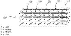
하나의 컬러의 노즐에 의해서 인쇄된 도트는 동시에 다른 컬러에 의해서 인쇄된 것과는 다른 라인을 위한 것이나, 크로마파드(chromapod)의 각각의 파드가 차례로 도트의 동일 그룹을 인쇄하도록 다른 컬러의 파드가 배치되는 크로마파드를 형성하기 위해서 각각의 다른 컬러의 하나의 파드는 함께 그룹화될 수 있다.A dot printed by a nozzle of one color is for a line different from that printed by another color at the same time, but a pod of a different color is placed so that each pod of a chromapod in turn prints the same group of dots. One pod of each different color can be grouped together to form a chromapod.
시안, 마젠타, 옐로우 및 블랙의 하나의 파드는 크로마파드로 그룹화될 수 있다. 크로마파드는 다른 라인상의 10개의 도트의 동일 수평 세트의 다른 컬러 구성요소를 표현한다. 다른 컬러 파드 사이의 정확한 거리는 일정수의 도트-폭이고, 따라서 인쇄할 때 고려되어야 한다: 인쇄 알고리즘은 컬러 사이의 도트-폭의 가변 거리에 대해서 허용하여야 한다.One pod of cyan, magenta, yellow and black can be grouped into a chromapad. Chromapads represent different color components of the same horizontal set of 10 dots on different lines. The exact distance between different color pods is a certain number of dot-widths, and therefore must be considered when printing: the printing algorithm must allow for variable distances of dot-width between colors.
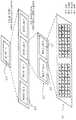
이네이블된 파드그룹에서의 노즐의 그룹이 일정 파이어링 페이즈 동안에 동시에 파이어링되는 페이즈그룹으로 하나 이상의 크로마파드가 형성될 수 있다. 페이즈그룹의 파드그룹의 하나 이상은 요구되는 인쇄 속도에 의존해서 동시에 이네이블된다.One or more chroma pods may be formed as a phase group in which a group of nozzles in the enabled pod group is fired simultaneously during a predetermined firing phase. One or more of the podgroups of the phasegroup are enabled simultaneously depending on the required print speed.
5개의 크로마파드가 단일 파드그룹으로 편성될 수 있다. 각각의 크로마파드는 40개의 노즐을 포함할 수 있기 때문에, 각각의 파드그룹은 200개의 노즐(50개의 시안, 50개의 마젠타, 50개의 옐로우, 및 50개의 블랙 노즐)을 포함할 수 있다.Five chroma pods can be organized into a single pod group. Since each chromapod can contain 40 nozzles, each podgroup can contain 200 nozzles (50 cyan, 50 magenta, 50 yellow, and 50 black nozzles).
2개의 파드그룹이 단일 페이즈그룹으로 편성될 수 있다. 페이즈그룹은 페이즈그룹내의 노즐의 그룹이 일정 파이어링 페이즈 동안에 동시에 파이어링되기 때문에 그렇게 명명된다. 2개의 파드그룹으로부터 페이즈그룹의 형성은 2개의 파드그룹이네이블 라인을 통해서 저속 및 고속 인쇄를 전부 허용한다.Two pod groups can be organized into a single phase group. The phase group is so named because the group of nozzles within the phase group are fired simultaneously during a certain firing phase. The formation of a phasegroup from two podgroups allows both low and high speed printing through the two podgroup enable lines.
2개의 페이즈그룹은 단일 파이어그룹(firegroup)으로 편성될 수 있고, 각각의 세그먼트에는 4개의 파이어그룹이 있다. 파이어그룹은 그들이 모두 동일 노즐을 동시에 파이어링하기 때문에 그렇게 명명된다. 2개의 이네이블 라인은 다른 파이어링 페이즈로서 독립적으로 페이즈그룹의 노즐의 파이어링을 허용한다.The two phasegroups can be organized into a single firegroup, and each segment has four firegroups. Firegroups are so named because they all fire the same nozzle at the same time. The two enable lines allow the firing of the nozzles of the phase group independently as different firing phases.
4-인치 프린트헤드는 전형적으로 8개의 세그먼트로 나란히 구성될 것이고, 각각의 세그먼트는 4개의 파이어그룹을 가질 것이다.A 4-inch printhead will typically consist of 8 segments side by side, each segment will have 4 firegroups.
더 넓은 프린트헤드는 프린트헤드의 2개를 함께 조립함으로써 만들어질 수 있다. 그래서 8-인치 프린트헤드는 총 51,200개의 노즐에 대해서 2개의 4-인치 프린트헤드로 구성된다.Wider printheads can be made by assembling two of the printheads together. So the 8-inch printhead consists of two 4-inch printheads for a total of 51,200 nozzles.
노즐 계층은 고른 전력 소비를 유지하면서 오버래핑 페이즈 및 다중 속도를 허용한다. 더하여, 노즐 그룹화 파드는 물리적 안정성을 제공한다.The nozzle layer allows for overlapping phases and multiple speeds while maintaining even power consumption. In addition, the nozzle grouping pod provides physical stability.
전력 소비의 견지에서, 노즐 그룹화는 속도/전력 소비가 다른 제품 구성에서 교환(trade-off)되게 하기 위해서 저속 및 고속 인쇄 모드를 이네이블한다.In terms of power consumption, nozzle grouping enables low speed and high speed print modes to allow speed/power consumption to be trade-off in different product configurations.
단일 4-인치 프린트헤드는 총 25,600개의 노즐을 포함할 수 있다. 인쇄 사이클은 인쇄될 정보에 의존하여 모든 이들 노즐까지의 파이어링을 수반한다. 그들을 모두 동시에 파이어링하는 것은 너무 많은 전력을 소비하고 잉크 리필 및 노즐 간섭의 견지에서 문제일 것이다. 더 나아가, 노즐의 파이어링은 또한 그 노즐 파드의 공통 잉크통내에서 제한된 시간 동안 음향 섭동을 일으킨다. 섭동은 동일 파드내의 또 다른 노즐의 파이어링과 간섭할 수 있다. 결과적으로, 파드내의 노즐의 파이어링은 가능한 서로로부터 오프셋되어야 한다.A single 4-inch printhead can contain a total of 25,600 nozzles. The print cycle involves firing up to all these nozzles depending on the information to be printed. Firing them all at the same time consumes too much power and will be a problem in terms of ink refill and nozzle interference. Furthermore, the firing of the nozzles also causes acoustic perturbation for a limited time in the common inkwell of the nozzle pod. The perturbation can interfere with the firing of another nozzle in the same pod. Consequently, the firing of the nozzles in the pod should be offset from each other as much as possible.
이것을 다루기 위해서, 컬러 당 하나의 노즐이 크로마파드로부터 파이어링될 수 있고 그 후 파드그룹내의 다음 크로마파드로부터 노즐이 파이어링될 수 있다.To handle this, one nozzle per color can be fired from a chromapod and then a nozzle can be fired from the next chromapod in the pod group.
2개의 파이어링 모드(저속 인쇄 모드 및 고속 인쇄 모드)가 정의될 수 있다.Two firing modes (low speed print mode and high speed print mode) can be defined.
저속 인쇄 동안에, 각각의 페이즈그룹의 하나의 파드그룹만이 파이어링 펄스를 수신해서 2개중 하나의 파드그룹만이 노즐을 파이어링한다. 저속 인쇄 모드에서 2개의 파드그룹내의 크로마파드는 처음 크로마파드가 다시 파이어링하기 전에 모두 파이어링해야 한다.During low-speed printing, only one Podgroup in each phasegroup receives the firing pulse and only one Podgroup out of the two fires the nozzle. In slow print mode, all chromapods in two Podgroups must be fired before the first chromapod fires again.
저속 인쇄 모드에서, 128개의 노즐이 각각의 4-인치 프린트헤드로부터 동시에 파이어링될 수 있다. 파이어링된 노즐은 최대로 멀어야 하고, 그래서 16개의 노즐이 각각의 8개의 세그먼트로부터 파이어링된다. 모든 25,600개의 노즐을 파이어링하기 위해서, 128개의 노즐의 200개의 다른 세트가 파이어링되어야 한다.In the slow print mode, 128 nozzles can be fired simultaneously from each 4-inch printhead. The fired nozzles should be maximally distant, so 16 nozzles are fired from each of the 8 segments. In order to fire all 25,600 nozzles, 200 different sets of 128 nozzles must be fired.
고속 인쇄 동안에, 2개의 파드그룹이 설정되어, 2개의 파드그룹이 노즐을 파이어링한다. 고속 인쇄 모드에서 단일 파드그룹내의 크로마파드는 처음 크로마파드 가 다시 파이어링하기 전에 모두 파이어링해야 한다.During high-speed printing, two podgroups are set up, so that two podgroups fire nozzles. In high speed print mode, all chromapods within a single Podgroup must be fired before the first chromapod fires again.
고속 인쇄 모드에서, 256개의 노즐이 각각의 4-인치 프린트헤드로부터 동시에 파이어링될 수 있다. 파이어링된 노즐은 최대로 멀어야 하고, 그래서 32개의 노즐이 각각의 세그먼트로부터 파이어링된다. 모든 25,600개의 노즐을 파이어링하기 위해서, 256개의 노즐의 100개의 다른 세트가 파이어링되어야 한다.In the high speed print mode, 256 nozzles can be fired simultaneously from each 4-inch printhead. The fired nozzles should be maximally distant, so 32 nozzles are fired from each segment. In order to fire all 25,600 nozzles, 100 different sets of 256 nozzles must be fired.
고속 인쇄가 동시에 두 배의 노즐을 파이어링하기 때문에 결과적으로 저속 인쇄는 고속 인쇄보다 두 배의 시간이 걸린다. 저속 모드에서의 전력 소비는 고속 모드의 전력 소비의 반이다. 그러나, 페이지를 인쇄하는데 소비되는 에너지는 두가지 경우에서 동일함을 주목하라.As high-speed printing fires twice as many nozzles at the same time, as a result, low-speed printing takes twice as long as high-speed printing. The power consumption in the low speed mode is half of the power consumption in the high speed mode. Note, however, that the energy consumed to print the page is the same in both cases.
프린트헤드는 파이어링 펄스의 타이밍을 조절하기 위해서 피드백의 수개의 라인을 산출한다. 하나의 피드백 신호는 프린트헤드가 얼마나 뜨거운지를 제어기에게 알려준다. 이것은 온도가 잉크의 점성에 영향을 미치기 때문에, 제어기가 파이어링 펄스의 타이밍을 조절하게 한다. 제 2 피드백 신호는 얼마나 많은 전압이 액추에이터에 이용될 수 있는지를 제어기에게 알려준다. 이것은 펄스 폭을 조절함으로써 제어기가 플랫 배터리 또는 고전압원에 대해 보상하게 한다. 제 3 피드백 신호는 액추에이터 히터의 저항률(스퀘어 당 옴)을 제어기에게 알려준다. 이것은 히터 저항률에 관계없이 일정한 에너지를 유지하기 위해서 제어기가 펄스 폭을 조절하게 한다. 제 4 피드백 신호는 리소그래픽 및 에칭 편차에 기인하여 ±5%까지 변할 수 있는 히터의 임계부의 폭을 제어기에게 알려준다. 이것은 제어기가 펄스 폭을 적절히 조절하게 한다.The printhead produces several lines of feedback to control the timing of the firing pulses. One feedback signal tells the controller how hot the printhead is. This allows the controller to adjust the timing of the firing pulses since temperature affects the viscosity of the ink. The second feedback signal tells the controller how much voltage is available to the actuator. This allows the controller to compensate for flat batteries or high voltage sources by adjusting the pulse width. The third feedback signal informs the controller of the resistivity (ohms per square) of the actuator heater. This allows the controller to adjust the pulse width to maintain a constant energy regardless of the heater resistivity. The fourth feedback signal informs the controller of the width of the critical portion of the heater, which can vary by ±5% due to lithographic and etch variations. This allows the controller to properly adjust the pulse width.
로드 사이클은 후속 인쇄 사이클 동안에 인쇄될 정보로써 프린트헤드의 로딩 업을 수반한다. 각각의 노즐의 파이어링 제어 포트는 노즐이 인쇄 사이클 동안에 파이어링할 것인지 아닌지를 결정하는 연관 노즐이네이블 비트를 가질 수 있다. 노즐이네이블 비트는 시프트 레지스터의 세트를 통해서 로드 사이클 동안 로딩된다. 모든 시프트 레지스터가 완전히 로딩되면, 모든 비트는 적합한 노즐이네이블 비트에 병렬로 전송된다. 전송이 일어난 직후, 인쇄 사이클이 시작될 수 있다. 인쇄 사이클 및 로드 사이클은 모든 노즐이네이블 비트의 병렬 로드가 인쇄 사이클의 끝에 일어나는 한 동시에 일어날 수 있다.The load cycle entails loading up the printhead with information to be printed during subsequent print cycles. The firing control port of each nozzle may have an associated nozzle enable bit that determines whether or not the nozzle will fire during the print cycle. The nozzle enable bit is loaded during the load cycle through a set of shift registers. When all shift registers are fully loaded, all bits are transferred in parallel to the appropriate nozzle enable bit. Immediately after the transfer has taken place, the print cycle can be started. The print cycle and load cycle can occur simultaneously as long as parallel loading of all nozzle enable bits occurs at the end of the print cycle.
인쇄 프로세스는 프린트헤드에 대하여 정확한 순서로 데이터를 산출해야 한다. 예로서, 제 1 클록 펄스는 다음 인쇄 사이클의 도트 0, 800, 1600, 2400, 3200, 4000, 4800, 및 5600에 대하여 CMYK 비트를 전송할 수 있다. 제 2 클록 펄스는 다음 인쇄 사이클의 도트 1, 801, 1601, 2401, 3201, 4001, 4801, 및 5601에 대하여 CMYK 비트를 전송할 수 있다. 800 SR클록 펄스 후에, 전송 펄스가 주어질 수 있다.The printing process must produce the data in the correct order for the printhead. As an example, the first clock pulse may transmit CMYK bits for
물론, 800 SR클록 펄스내에서, 시프트 레지스터는 노즐이네이블 비트로의 최종 전송과의 통신에 따라 로딩되어야 하고, 여기서 많은 다른 배선 가능성이 존재한다. 하나의 로딩(따라서 배선) 가능성은 비트를 파드 순서대로 로딩하는 것인데, 각각의 파드내에서 비트는 파드의 하나의 측으로부터 다른 측으로의 각각의 노즐을 표현한다(제 1 행에서의 제 2 노즐상으로의 이동 전에 제 1 행으로부터 마지막 행으로까지 제 1 노즐을 효과적으로 로딩). 2개의 행 파드에서 이것은 외견상 지그- 재그 방식으로 노즐을 로딩하는 것을 의미한다. 또 다른 가능성은 비트를 파드 순서대로 로딩하는 것인데, 각각의 파드내에서 비트는 각각의 행을 표현하고, 각각의 행내에서 파드의 하나의 측으로부터 다른 측으로 노즐에서부터 시작한다.Of course, within 800 SR clock pulses, the shift register must be loaded upon communication with the last transmission to the nozzle enable bit, where there are many other wiring possibilities. One loading (and thus wiring) possibility is to load the bits in pod order, in which bits within each pod represent each nozzle from one side of the pod to the other (on the second nozzle in the first row). Effectively loading the first nozzle from the first row to the last row before moving to). In the two row pod this means loading the nozzle in a seemingly jig-zag manner. Another possibility is to load the bits in pod order, in which bits within each pod represent each row, starting from the nozzle from one side of the pod to the other within each row.
홀수 및 짝수 CMYK 출력은, 동일 인쇄 사이클 동안에 인쇄되더라도, 동일한 물리적 출력 라인상에 나타나지 않는다는 것을 주목하는 것은 중요하다. 다른 컬러의 노즐 사이의 분리뿐만 아니라 프린트헤드내에서의 홀수 및 짝수 노즐의 물리적 분리는 그들이 페이지의 다른 라인상에 도트를 산출할 것을 보장한다. 이러한 상대적 차이는 데이터를 프린트헤드내로 로딩할 때에 대해서 고려되어야 한다. 라인에서의 실제 차이는 프린트헤드에서 사용된 잉크젯 메카니즘의 특성에 의존한다. 그 차이는 다른 컬러의 노즐 사이의 거리 및 동일 컬러의 노즐 사이의 거리를 표현하는 변수에 의해서 정해질 수 있다.It is important to note that odd and even CMYK outputs, even if printed during the same print cycle, do not appear on the same physical output line. The separation between nozzles of different colors as well as the physical separation of odd and even nozzles within the printhead ensures that they will produce dots on different lines of the page. This relative difference must be taken into account when loading data into the printhead. The actual difference in line depends on the nature of the inkjet mechanism used in the printhead. The difference can be determined by a variable representing the distance between nozzles of different colors and between nozzles of the same color.
본 발명은 잉크 공급 포트, 잉크 증착 포트 및 프린트헤드의 파이어링 사이클 동안에 증착 포트로부터 잉크 도트가 증착되어지게 하는(파이어링) 신호를 수신하는 파이어링 제어 포트를 각각 갖는 복수의 노즐을 포함하는, 컬러 프린터용 모듈러 프린트헤드이다. 프린트헤드의 노즐은 그룹 또는 파드에 배치되고, 각각의 파드의 노즐의 잉크 공급 포트는 공통 잉크 공급 라인에 접속되어 있다. 각각의 파드의 노즐은 행(행은 인쇄될 페이지를 가로지르는 방향으로 뻗어 있다)에 배치되고, 각각의 행의 노즐이 동시에 파이어링된다면 도트를 다른 라인상으로 증착시키도록 노즐의 행은 서로로부터 오프셋된다. 선택된 상호 배제적인 노즐 서브-그룹이 파이어링 사이클의 소정 페이즈에서 그들이 동시에 파이어링되게 하도록 게이팅된 그들 의 파이어링 제어 포트를 갖는 동작 그룹내로 각각의 다른 컬러의 파드가 함께 배치된다.The present invention comprises a plurality of nozzles each having an ink supply port, an ink deposition port, and a firing control port for receiving a signal to cause an ink dot to be deposited (firing) from the deposition port during a firing cycle of the printhead, It is a modular printhead for color printers. The nozzles of the printhead are arranged in groups or pods, and the ink supply ports of the nozzles of each pod are connected to a common ink supply line. The nozzles of each Pod are placed in a row (rows extend across the page to be printed), and if the nozzles in each row are fired at the same time, the rows of nozzles are separated from each other to deposit dots onto different lines. Is offset. Pods of each different color are placed together into an operation group having their firing control ports gated so that selected mutually exclusive nozzle sub-groups cause them to fire simultaneously in a given phase of the firing cycle.
일 예에서 각각의 파드에 노즐의 2개의 행이 존재하고 하나의 행의 노즐은 페이지상의 하나의 라인을 따라 짝수 도트를 증착시키고, 다른 행의 노즐은 페이지상의 인접 라인을 따라 홀수 도트를 증착시킨다.In one example, there are two rows of nozzles in each pod, one row of nozzles deposits even dots along one line on the page, and the other row of nozzles deposits odd dots along adjacent lines on the page. .
노즐의 행 사이의 오프셋의 양은 노즐 아래의 용지의 흐름과 매칭하도록 디자인된다.The amount of offset between the rows of nozzles is designed to match the flow of paper under the nozzles.
각각의 파드의 노즐은 제 1 측으로부터 시작하는 제 1 행을 따라서, 그리고 그 후 다른 측에서 끝나는 동일한 방향으로의 다른 행을 따라서 순서대로 파이어링될 수 있다.The nozzles of each pod may be fired in sequence along a first row starting from the first side and then along another row in the same direction ending on the other side.
단일 파드는 공통 잉크통을 공유하는 10개의 노즐로 구성될 수 있다. 5개의 노즐은 하나의 행에 있고, 5개는 또 다른 행에 있다. 각각의 노즐은 15.875mm 격자상에 일정 간격으로 이격된 직경 22.5mm 도트를 산출할 수 있다.A single pod can consist of 10 nozzles sharing a common ink reservoir. Five nozzles are in one row and five are in another row. Each nozzle can produce 22.5mm diameter dots spaced at regular intervals on a 15.875mm grid.
하나의 컬러의 노즐에 의해서 인쇄된 도트가 동시에 다른 컬러에 의해서 인쇄된 것과는 다른 라인을 위한 것이나, 크로마파드의 각각의 파드가 차례로 도트의 동일 그룹을 인쇄하도록 다른 컬러의 파드가 배치되는 크로마파드를 형성하기 위해서 각각의 다른 컬러의 하나의 파드는 함께 그룹화될 수 있다.The dots printed by the nozzles of one color are for lines different from those printed by the other colors at the same time, but the pods of different colors are arranged so that each pod of the chromapods in turn prints the same group of dots. One Pod of each different color can be grouped together to form.
시안, 마젠타, 옐로우 및 블랙의 하나의 파드는 크로마파드로 그룹화될 수 있다. 크로마파드는 다른 라인상의 10개의 도트의 동일 수평 세트의 다른 컬러 구성요소를 표현한다. 다른 컬러 파드 사이의 정확한 거리는 일정수의 도트-폭이고, 따라서 인쇄할 때 고려되어야 한다: 인쇄 알고리즘은 컬러 사이의 도트-폭의 가변 거리에 대해서 허용하여야 한다.One pod of cyan, magenta, yellow and black can be grouped into a chromapad. Chromapads represent different color components of the same horizontal set of 10 dots on different lines. The exact distance between different color pods is a certain number of dot-widths, and therefore must be considered when printing: the printing algorithm must allow for variable distances of dot-width between colors.
이네이블된 파드그룹에서의 노즐의 그룹이 일정 파이어링 페이즈 동안에 동시에 파이어링되는 페이즈그룹으로 하나 이상의 크로마파드가 형성될 수 있다. 페이즈그룹의 파드그룹의 하나 이상은 요구되는 인쇄 속도에 의존해서 동시에 이네이블된다.One or more chroma pods may be formed as a phase group in which a group of nozzles in the enabled pod group is fired simultaneously during a predetermined firing phase. One or more of the podgroups of the phasegroup are enabled simultaneously depending on the required print speed.
5개의 크로마파드가 단일 파드그룹으로 편성될 수 있다. 각각의 크로마파드는 40개의 노즐을 포함할 수 있기 때문에, 각각의 파드그룹은 200개의 노즐(50개의 시안, 50개의 마젠타, 50개의 옐로우, 및 50개의 블랙 노즐)을 포함할 수 있다.Five chroma pods can be organized into a single pod group. Since each chromapod can contain 40 nozzles, each podgroup can contain 200 nozzles (50 cyan, 50 magenta, 50 yellow, and 50 black nozzles).
2개의 파드그룹이 단일 페이즈그룹으로 편성될 수 있다. 페이즈그룹은 페이즈그룹내의 노즐의 그룹이 일정 파이어링 페이즈 동안에 동시에 파이어링되기 때문에 그렇게 명명된다. 2개의 파드그룹으로부터 페이즈그룹의 형성은 2개의 파드그룹이네이블 라인을 통해서 저속 및 고속 인쇄를 전부 허용한다.Two pod groups can be organized into a single phase group. The phase group is so named because the group of nozzles within the phase group are fired simultaneously during a certain firing phase. The formation of a phasegroup from two podgroups allows both low and high speed printing through the two podgroup enable lines.
2개의 페이즈그룹은 단일 파이어그룹으로 편성될 수 있고, 각각의 세그먼트에는 4개의 파이어그룹이 있다. 파이어그룹은 그들이 모두 동일 노즐을 동시에 파이어링하기 때문에 그렇게 명명된다. 2개의 이네이블 라인은 다른 파이어링 페이즈로서 독립적으로 페이즈그룹의 노즐의 파이어링을 허용한다.The two phasegroups can be organized into a single firegroup, and each segment has four firegroups. Firegroups are so named because they all fire the same nozzle at the same time. The two enable lines allow the firing of the nozzles of the phase group independently as different firing phases.
4-인치 프린트헤드는 전형적으로 8개의 세그먼트로 나란히 구성될 것이고, 각각의 세그먼트는 4개의 파이어그룹을 가질 것이다.A 4-inch printhead will typically consist of 8 segments side by side, each segment will have 4 firegroups.
더 넓은 프린트헤드는 프린트헤드의 2개를 함께 조립함으로써 만들어질 수 있다. 그래서 8-인치 프린트헤드는 총 51,200개의 노즐에 대해서 2개의 4-인치 프린트헤드로 구성된다.Wider printheads can be made by assembling two of the printheads together. So the 8-inch printhead consists of two 4-inch printheads for a total of 51,200 nozzles.
노즐 계층은 고른 전력 소비를 유지하면서 오버래핑 페이즈 및 다중 속도를 허용한다. 더하여, 노즐 그룹화 파드는 물리적 안정성을 제공한다.The nozzle layer allows for overlapping phases and multiple speeds while maintaining even power consumption. In addition, the nozzle grouping pod provides physical stability.
전력 소비의 견지에서, 노즐 그룹화는 속도/전력 소비가 다른 제품 구성에서 교환되게 하기 위해서 저속 및 고속 인쇄 모드를 이네이블한다.In terms of power consumption, nozzle grouping enables low speed and high speed print modes to allow speed/power consumption to be exchanged in different product configurations.
단일 4-인치 프린트헤드는 총 25,600개의 노즐을 포함할 수 있다. 인쇄 사이클은 인쇄될 정보에 의존하여 모든 이들 노즐까지의 파이어링을 수반한다. 그들을 모두 동시에 파이어링하는 것은 너무 많은 전력을 소비하고 잉크 리필 및 노즐 간섭의 견지에서 문제일 것이다. 더 나아가, 노즐의 파이어링은 또한 그 노즐 파드의 공통 잉크통내에서 제한된 시간 동안 음향 섭동을 일으킨다. 섭동은 동일 파드내의 또 다른 노즐의 파이어링과 간섭할 수 있다. 결과적으로, 파드내의 노즐의 파이어링은 가능한 서로로부터 오프셋되어야 한다.A single 4-inch printhead can contain a total of 25,600 nozzles. The print cycle involves firing up to all these nozzles depending on the information to be printed. Firing them all at the same time consumes too much power and will be a problem in terms of ink refill and nozzle interference. Furthermore, the firing of the nozzles also causes acoustic perturbation for a limited time in the common inkwell of the nozzle pod. The perturbation can interfere with the firing of another nozzle in the same pod. Consequently, the firing of the nozzles in the pod should be offset from each other as much as possible.
이것을 다루기 위해서, 컬러 당 하나의 노즐이 크로마파드로부터 파이어링될 수 있고 그 후 파드그룹내의 다음 크로마파드로부터 노즐이 파이어링될 수 있다.To handle this, one nozzle per color can be fired from a chromapod and then a nozzle can be fired from the next chromapod in the pod group.
2개의 파이어링 모드(저속 인쇄 모드 및 고속 인쇄 모드)가 정의될 수 있다.Two firing modes (low speed print mode and high speed print mode) can be defined.
저속 인쇄 동안에, 각각의 페이즈그룹의 하나의 파드그룹만이 파이어링 펄스를 수신해서 2개중 하나의 파드그룹만이 노즐을 파이어링한다. 저속 인쇄 모드에서 2개의 파드그룹내의 크로마파드는 처음 크로마파드가 다시 파이어링하기 전에 모두 파이어링해야 한다.During low-speed printing, only one Podgroup in each phasegroup receives the firing pulse and only one Podgroup out of the two fires the nozzle. In slow print mode, all chromapods in two Podgroups must be fired before the first chromapod fires again.
저속 인쇄 모드에서, 128개의 노즐이 각각의 4-인치 프린트헤드로부터 동시에 파이어링될 수 있다. 파이어링된 노즐은 최대로 멀어야 하고, 그래서 16개의 노즐이 각각의 8개의 세그먼트로부터 파이어링된다. 모든 25,600개의 노즐을 파이어링하기 위해서, 128개의 노즐의 200개의 다른 세트가 파이어링되어야 한다.In the slow print mode, 128 nozzles can be fired simultaneously from each 4-inch printhead. The fired nozzles should be maximally distant, so 16 nozzles are fired from each of the 8 segments. In order to fire all 25,600 nozzles, 200 different sets of 128 nozzles must be fired.
고속 인쇄 동안에, 2개의 파드그룹이 설정되어서, 2개의 파드그룹이 노즐을 파이어링한다. 고속 인쇄 모드에서 단일 파드그룹내의 크로마파드는 처음 크로마파드가 다시 파이어링하기 전에 모두 파이어링해야 한다.During high-speed printing, two podgroups are set, so that two podgroups fire nozzles. In high speed print mode, all chromapods within a single Podgroup must be fired before the first chromapod fires again.
고속 인쇄 모드에서, 256개의 노즐이 각각의 4-인치 프린트헤드로부터 동시에 파이어링될 수 있다. 파이어링된 노즐은 최대로 멀어야 하고, 그래서 32개의 노즐이 각각의 세그먼트로부터 파이어링된다. 모든 25,600개의 노즐을 파이어링하기 위해서, 256개의 노즐의 100개의 다른 세트가 파이어링되어야 한다.In the high speed print mode, 256 nozzles can be fired simultaneously from each 4-inch printhead. The fired nozzles should be maximally distant, so 32 nozzles are fired from each segment. In order to fire all 25,600 nozzles, 100 different sets of 256 nozzles must be fired.
고속 인쇄가 동시에 두 배의 노즐을 파이어링하기 때문에 결과적으로 저속 인쇄는 고속 인쇄보다 두 배의 시간이 걸린다. 저속 모드에서의 전력 소비는 고속 모드의 전력 소비의 반이다. 그러나, 페이지를 인쇄하는데 소비되는 에너지는 두가지 경우에서 동일함을 주목하라.As high-speed printing fires twice as many nozzles at the same time, as a result, low-speed printing takes twice as long as high-speed printing. The power consumption in the low speed mode is half of the power consumption in the high speed mode. Note, however, that the energy consumed to print the page is the same in both cases.
프린트헤드는 파이어링 펄스의 타이밍을 조절하기 위해서 피드백의 수개의 라인을 산출한다. 하나의 피드백 신호는 프린트헤드가 얼마나 뜨거운지를 제어기에게 알려준다. 이것은 온도가 잉크의 점성에 영향을 미치기 때문에, 제어기가 파이어링 펄스의 타이밍을 조절하게 한다. 제 2 피드백 신호는 얼마나 많은 전압이 액추에이터에 이용될 수 있는지를 제어기에게 알려준다. 이것은 펄스 폭을 조절함으 로써 제어기가 플랫 배터리 또는 고전압원에 대해 보상하게 한다. 제 3 피드백 신호는 액추에이터 히터의 저항률(스퀘어 당 옴)을 제어기에게 알려준다. 이것은 히터 저항률에 관계없이 일정한 에너지를 유지하기 위해서 제어기가 펄스 폭을 조절하게 한다. 제 4 피드백 신호는 리소그래픽 및 에칭 편차에 기인하여 ±5%까지 변할 수 있는, 히터의 임계부의 폭을 제어기에게 알려준다. 이것은 제어기가 펄스 폭을 적절히 조절하게 한다.The printhead produces several lines of feedback to control the timing of the firing pulses. One feedback signal tells the controller how hot the printhead is. This allows the controller to adjust the timing of the firing pulses since temperature affects the viscosity of the ink. The second feedback signal tells the controller how much voltage is available to the actuator. This allows the controller to compensate for flat batteries or high voltage sources by adjusting the pulse width. The third feedback signal informs the controller of the resistivity (ohms per square) of the actuator heater. This allows the controller to adjust the pulse width to maintain a constant energy regardless of the heater resistivity. The fourth feedback signal informs the controller of the width of the critical portion of the heater, which can vary by ±5% due to lithographic and etch variations. This allows the controller to properly adjust the pulse width.
로드 사이클은 후속 인쇄 사이클 동안에 인쇄될 정보로써 프린트헤드의 로딩 업을 수반한다. 각각의 노즐의 파이어링 제어 포트는 노즐이 인쇄 사이클 동안에 파이어링할 것인지 아닌지를 결정하는 연관 노즐이네이블 비트를 가질 수 있다. 노즐이네이블 비트는 시프트 레지스터의 세트를 통해서 로드 사이클 동안 로딩된다. 모든 시프트 레지스터가 완전히 로딩되면, 모든 비트는 적합한 노즐이네이블 비트에 병렬로 전송된다. 전송이 일어난 직후, 인쇄 사이클이 시작될 수 있다. 인쇄 사이클 및 로드 사이클은 모든 노즐이네이블 비트의 병렬 로드가 인쇄 사이클의 끝에 일어나는 한 동시에 일어날 수 있다.The load cycle entails loading up the printhead with information to be printed during subsequent print cycles. The firing control port of each nozzle may have an associated nozzle enable bit that determines whether or not the nozzle will fire during the print cycle. The nozzle enable bit is loaded during the load cycle through a set of shift registers. When all shift registers are fully loaded, all bits are transferred in parallel to the appropriate nozzle enable bit. Immediately after the transfer has taken place, the print cycle can be started. The print cycle and load cycle can occur simultaneously as long as parallel loading of all nozzle enable bits occurs at the end of the print cycle.
인쇄 프로세스는 프린트헤드에 대하여 정확한 순서로 데이터를 산출해야 한다. 예로서, 제 1 클록 펄스는 다음 인쇄 사이클의 도트 0, 800, 1600, 2400, 3200, 4000, 4800, 및 5600에 대하여 CMYK 비트를 전송할 수 있다. 제 2 클록 펄스는 다음 인쇄 사이클의 도트 1, 801, 1601, 2401, 3201, 4001, 4801, 및 5601에 대하여 CMYK 비트를 전송할 수 있다. 800 SR클록 펄스 후에, 전송 펄스가 주어질 수 있다.The printing process must produce the data in the correct order for the printhead. As an example, the first clock pulse may transmit CMYK bits for
물론, 800 SR클록 펄스내에서, 시프트 레지스터는 노즐이네이블 비트로의 최종 전송과의 통신에 따라 로딩되어야 하고, 여기서 많은 다른 배선 가능성이 존재한다. 하나의 로딩(따라서 배선) 가능성은 비트를 파드 순서대로 로딩하는 것인데, 각각의 파드내에서 비트는 파드의 하나의 측으로부터 다른 측으로의 각각의 노즐을 표현한다(제 1 행에서의 제 2 노즐상으로의 이동 전에 제 1 행으로부터 마지막 행으로까지 제 1 노즐을 효과적으로 로딩). 2개의 행 파드에서 이것은 외견상 지그-재그 방식으로 노즐을 로딩하는 것을 의미한다. 또 다른 가능성은 비트를 파드 순서대로 로딩하는 것인데, 각각의 파드내에서 비트는 각각의 행을 표현하고, 각각의 행내에서 파드의 하나의 측으로부터 다른 측으로 노즐에서부터 시작한다.Of course, within 800 SR clock pulses, the shift register must be loaded upon communication with the last transmission to the nozzle enable bit, where there are many other wiring possibilities. One loading (and thus wiring) possibility is to load the bits in pod order, in which bits within each pod represent each nozzle from one side of the pod to the other (on the second nozzle in the first row). Effectively loading the first nozzle from the first row to the last row before moving to). In the two row pod this means loading the nozzle in a seemingly zig-zag manner. Another possibility is to load the bits in pod order, in which bits within each pod represent each row, starting from the nozzle from one side of the pod to the other within each row.
홀수 및 짝수 CMYK 출력은, 동일 인쇄 사이클 동안에 인쇄되더라도, 동일한 물리적 출력 라인상에 나타나지 않는다는 것을 주목하는 것은 중요하다. 다른 컬러의 노즐 사이의 분리뿐만 아니라 프린트헤드내에서의 홀수 및 짝수 노즐의 물리적 분리는 그들이 페이지의 다른 라인상에 도트를 산출할 것을 보장한다. 이러한 상대적 차이는 데이터를 프린트헤드내로 로딩할 때에 대해서 고려되어야 한다. 라인에서의 실제 차이는 프린트헤드에서 사용된 잉크젯 메카니즘의 특성에 의존한다. 그 차이는 다른 컬러의 노즐 사이의 거리 및 동일 컬러의 노즐 사이의 거리를 표현하는 변수에 의해서 정해질 수 있다.It is important to note that odd and even CMYK outputs, even if printed during the same print cycle, do not appear on the same physical output line. The separation between nozzles of different colors as well as the physical separation of odd and even nozzles within the printhead ensures that they will produce dots on different lines of the page. This relative difference must be taken into account when loading data into the printhead. The actual difference in line depends on the nature of the inkjet mechanism used in the printhead. The difference can be determined by a variable representing the distance between nozzles of different colors and between nozzles of the same color.
본 발명은 연속톤 컬러 층을 2-레벨로 하프토닝하고 블랙 층을 하프토닝된 연속톤 층 위로 합성시키기 위한 하프토너/합성기 유닛인데:The present invention is a halftoner/synthesizer unit for halftoning a contone color layer to two levels and synthesizing a black layer onto a halftoned contone layer:
일련의 연속톤 컬러 화소값의 형태를 갖는 확장된 연속톤 컬러 층 및 일련의 블랙 도트값의 형태를 갖는 확장된 블랙 층을 수신하는 입력 포트,An input port for receiving an extended contone color layer in the form of a series of contone color pixel values and an extended black layer in the form of a series of black dot values,
입력 포트에 수신된 각각의 연속톤 컬러 화소값을 디더링하고 각각의 컬러 구성요소에 대해서 2-레벨 출력 도트의 값을 결정하는 디더 유닛,A dither unit for dithering each contone color pixel value received at the input port and determining the value of a 2-level output dot for each color component,
디더 유닛으로부터의 2-레벨 출력 도트의 값 및 입력 포트로부터의 블랙 도트값을 수신하고, 예를 들어, 블랙 도트의 값이 완전한 불투명도를 표현할 때 그 때 각각의 컬러에 대해 하프토닝된 도트의 값이 컬러를 표현하지 않게 설정되도록 블랙 층을 하프토닝된 층 위로 합성하는 합성 유닛,When receiving the value of the 2-level output dot from the dither unit and the value of the black dot from the input port, for example, the value of the dot halftoned for each color when the value of the black dot represents full opacity. A synthesis unit that combines the black layer onto the half-toned layer so that this color is not expressed,
연속톤 컬러 화소 입력, 블랙 도트 입력, 및 도트 출력을 클록킹하기 위한 이네이블 신호를 발생시키는 클록 이네이블 발생기,A clock enable generator for generating an enable signal for clocking a contone color pixel input, a black dot input, and a dot output,
분리된 컬러 평면을 가질 수 있는 일련의 2-레벨 도트의 형태를 갖는 2-레벨 이미지 라인의 세트를 배달하는 출력 포트를 포함한다.It includes an output port that delivers a set of two-level image lines in the form of a series of two-level dots that can have separate color planes.
출력은 1600 dpi 2-레벨 이미지 라인의 세트일 수 있다.The output may be a set of 1600 dpi two-level image lines.
컬러 연속톤 층은 CMYK 연속톤 층일 수 있다.The color contone layer may be a CMYK contone layer.
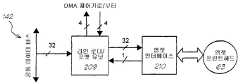
입력 연속톤 CMYK FIFO는 완전한 8KB 라인 버퍼를 포함할 수 있다. 각각의 라인은 한번 판독되고 그 후 라인 복제를 통해서 수직 업-스케일링을 성취하기 위해 연속톤 환산 계수(scale factor) 회 사용된다. FIFO 기록 번지 랩핑은 라인의 최종 복제된 사용의 시작 때까지 디스에이블되는데, 그 때 클록 이네이블 발생기는 랩핑(wrapping)을 이네이블하는 연속톤 라인 전진 이네이블 신호를 발생시킨다.The input contone CMYK FIFO can contain a complete 8KB line buffer. Each line is read once and then used a contone scale factor times to achieve vertical up-scaling through line duplication. FIFO write address wrapping is disabled until the start of the last replicated use of the line, at which time the clock enable generator generates a contone line advance enable signal that enables wrapping.
대안은 주 메모리 연속톤 환산 계수 회로부터 라인을 판독하는 것인데, 메모리 트래픽을 65MB/s 만큼 증가시키지만 온-칩 8KB 라인 버퍼에 대한 필요를 피한 다.An alternative is to read the line from the main memory contone conversion factor circuit, which increases memory traffic by 65MB/s, but avoids the need for an on-chip 8KB line buffer.
유닛에 의해서 산출된 데이터의 소비자는 전형적으로 프린트헤드 인터페이스이다. 프린트헤드 인터페이스는 플래너 포맷, 즉, 분리된 컬러 평면을 갖는 2-레벨 이미지 데이터를 요구하기만 할 수는 없다. 그러나, 또한 그것은 짝수 및 홀수 화소가 분리되도록 요구할 수 있다. 컬러 연속톤 층이 CMYK 연속톤 층일 때 유닛의 출력 단계는 짝수 시안, 홀수 시안, 짝수 마젠타, 홀수 마젠타, 짝수 옐로우, 홀수 옐로우, 짝수 블랙, 및 홀수 블랙에 대하여 각각 하나씩 8 병렬 화소 FIFO를 사용할 수 있다.The consumer of the data produced by the unit is typically the printhead interface. The printhead interface cannot only request planner format, i.e. two-level image data with separate color planes. However, it may also require that even and odd pixels are separated. When the color contone layer is a CMYK contone layer, the output stage of the unit can use 8 parallel pixel FIFOs, one each for even cyan, odd cyan, even magenta, odd magenta, even yellow, odd yellow, even black, and odd black. have.
이러한 목적으로 클록 이네이블 발생기는 또한 출력 도트 FIFO의 짝수 또는 홀수 세트를 선택하는데 사용되는 짝수 신호를 발생시킬 수 있다.For this purpose, the clock enable generator can also generate an even signal that is used to select an even or odd set of output dot FIFOs.
시작된 후, 유닛은 페이지 끝 조건을 검출할 때까지, 또는 그 제어 레지스터를 통해서 명시적으로 중지될 때까지 계속할 수 있다.After being started, the unit can continue until it detects an end-of-page condition, or until explicitly stopped through its control register.
유닛은 지정된 폭 및 길이의 도트의 페이지를 발생시키고 많은 레지스터는 페이지 구조 및 매개 변수를 제어하기 위해서 데이터를 제공하는데 사용될 수 있다.The unit generates a page of dots of a specified width and length, and many registers can be used to provide data to control the page structure and parameters.
페이지 폭 레지스터는 프린트헤드의 폭에 대응할 수 있는 페이지 폭 데이터를 수신한다.The page width register receives page width data that may correspond to the width of the printhead.
페이지 길이 레지스터는 타겟 페이지의 길이에 대응할 수 있는 페이지 길이 데이터를 수신한다.The page length register receives page length data that may correspond to the length of the target page.
좌측 여백 레지스터는 좌측 여백의 위치를 기술하는 데이터를 수신한다.The left margin register receives data describing the location of the left margin.
우측 여백 레지스터는 우측 여백의 위치를 기술하는 데이터를 수신한다.The right margin register receives data describing the location of the right margin.
좌측 여백으로부터 우측 여백으로까지의 거리는 타겟 페이지 폭에 대응한다. 하프토너/합성기 유닛은 페이지 폭에 관하여 지정된 좌측 및 우측 여백 사이에 타겟 페이지 데이터를 발생시킨다.The distance from the left margin to the right margin corresponds to the target page width. The halftoner/compositor unit generates target page data between the left and right margins specified with respect to the page width.
블랙 페이지 폭 레지스터는 블랙 페이지 폭을 기술하는 데이터를 수신한다.The black page width register receives data describing the black page width.
연속톤 페이지 폭 레지스터는 연속톤 페이지 폭을 기술하는 데이터를 수신한다.The contone page width register receives data describing the contone page width.
하프토너/합성기 유닛은 지정된 블랙 및 연속톤 페이지 폭에 따라 블랙 및 연속톤 데이터를 소비한다.The halftoner/compositor unit consumes black and contone data according to the specified black and contone page width.
하프토너/합성기 유닛은 블랙 및 연속톤 데이터를 타겟 페이지 폭에 클리핑한다. 이것은 입력 FIFO 레벨에서 임의의 특별한 라인 끝 로직을 요구함이 없이 블랙 및 연속톤 페이지 폭이 타겟 페이지 폭을 초과하게 한다.The halftoner/compositor unit clips the black and contone data to the target page width. This allows the black and contone page widths to exceed the target page width without requiring any special end-of-line logic at the input FIFO level.
이러한 목적으로 클록 이네이블 발생기는 또한 현재 도트 위치가 페이지의 좌측 또는 우측 여백에 있을 때 화이트 도트를 발생시키는데 사용되는 여백 신호를 발생시킬 수 있다.For this purpose, the clock enable generator can also generate a margin signal that is used to generate a white dot when the current dot position is in the left or right margin of the page.
하프토너/합성기 유닛은 지정된 환산 계수에 수평 및 수직적으로 기초하여 프린터 해상도로 연속톤 데이터를 스케일링한다. 연속톤 환산 계수 레지스터는 연속톤 환산 계수를 수신하기 위해 제공될 수 있다. 이러한 환산 계수는 하프토너/합성기 유닛을 시작하기 이전에 연속톤 환산 계수 레지스터에 기록되어야 한다.The halftoner/synthesizer unit scales contone data with printer resolution based on the specified conversion factor horizontally and vertically. The contone conversion factor register may be provided to receive the contone conversion factor. These conversion factors must be recorded in the contone conversion factor register before starting the halftoner/synthesizer unit.
하프토너/합성기 제어 및 구성 레지스터는 이하의 표에 따라 요약될 수 있 다:The halftoner/synthesizer control and configuration registers can be summarized according to the table below:
디더 셀에서 볼륨의 각각의 도트 열은 256 별개의 비트로서 구현될 수 있다.In a dither cell, each dot column of a volume can be implemented as 256 distinct bits.
대안으로, 볼륨의 각각의 도트 열은 임계값의 고정 세트로서 구현될 수 있다. 3개의 8-비트 임계값을 사용하는 것은, 예를 들어, 24 비트를 소비할 뿐이다. 이제, n 임계값은 n+1 강도 인터발을 정하는데, 그 인터발내에서 대응 디더 셀 위치는 교대로 설정되지 않거나 설정되거나 한다. 디더링된 연속톤 화소값은 n+1 인터발 중 하나를 유일하게 선택하고, 이것은 대응 출력 도트의 값을 결정한다.Alternatively, each dot column of the volume can be implemented as a fixed set of thresholds. Using three 8-bit thresholds only consumes 24 bits, for example. Now, the n threshold value determines an n+1 intensity interval, within which the corresponding dither cell positions are not alternately set or set. The dithered contone pixel value uniquely selects one of the n+1 intervals, which determines the value of the corresponding output dot.
연속톤 데이터는 3중-임계값 64×64×3×8-비트(12KB) 디더 볼륨을 사용하여 디더링될 수 있다. 3개의 임계값은 하나의 사이클에서 디더 셀 ROM으로부터 검색될 수 있는 편리한 24-비트 값을 형성한다.Contone data can be dithered using a triple-threshold 64x64x3x8-bit (12KB) dither volume. The three thresholds form a convenient 24-bit value that can be retrieved from the dither cell ROM in one cycle.
디더 셀 일치가 컬러 평면 사이에 소망된다면, 그 때 동일 3중-임계값이 한번 검색되어 각각의 컬러 구성요소를 디더링하는데 사용될 수 있다.If dither cell matching is desired between color planes, then the same triple-threshold can be retrieved once and used to dither each color component.
디더 셀 일치가 소망되지 않는다면, 그 때 디더 셀은 4개의 서브셀로 분할되 어 4개의 개별적으로 번지 지정 가능한 ROM에 저장될 수 있는데, 그 ROM으로부터 4개의 다른 3중-임계값이 하나의 사이클에서 병렬로 검색될 수 있다. 4개의 컬러 평면은 서로로부터의 32 도트의 수직 및/또는 수평 오프셋에서 동일 디더 셀을 공유한다.If dither cell matching is not desired, then the dither cell can be divided into 4 subcells and stored in 4 individually addressable ROMs, from which 4 different triple-threshold values are assigned in one cycle. Can be searched in parallel at. The four color planes share the same dither cell at a vertical and/or horizontal offset of 32 dots from each other.
다중-임계값 디더 유닛이 사용될 수 있다. 예를 들어, 3중-임계값 유닛은 3중-임계값 및 강도값을 인터발 및 일 또는 제로 비트로 변환한다. 3중-임계 규칙은 이하 표에 나타내어진다.A multi-threshold dither unit can be used. For example, the triple-threshold unit converts the triple-threshold and intensity values into intervals and one or zero bits. The triple-critical rules are shown in the table below.
합성 유닛은 블랙 층 도트를 하프토닝된 CMYK 층 도트 위로 합성한다. 블랙 층 불투명도가 일이라면, 그 때 하프토닝된 CMY는 제로로 설정된다.The compositing unit synthesizes the black layer dots onto the halftoned CMYK layer dots. If the black layer opacity is 1, then the halftoned CMY is set to zero.
4-비트 하프토닝된 컬러 CcMcYcKc 및 1-비트 블랙 층 불투명도 Kb가 주어질 때, 합성 로직은 이하 표에서 정의되는 바와 같다:Given the 4-bit halftoned color Cc Mc Yc Kc and the 1-bit black layer opacity Kb , the synthesis logic is as defined in the table below:
클록 이네이블 발생기는 카운터의 세트를 사용한다. 카운터의 내부 로직은 이하 표에서 정의된다:The clock enable generator uses a set of counters. The internal logic of the counter is defined in the table below:
클록 이네이블 신호의 로직은 이하 표에서 정의된다:The logic of the clock enable signal is defined in the table below:
본 발명은 연속톤 컬러 화소값의 어레이의 형태를 갖는 연속톤 컬러 이미지를 2-레벨 도트로 디지털식으로 하프토닝하기 위한 디더 유닛이다. 디더 유닛은 디더 셀 위치가 교대로 설정되지 않고 설정되고 하도록 정해진 n+1 강도 인터발을 정하는 n 임계값의 고정 세트를, 각각의 디더 셀 위치에 대해서, 포함하는 디더 볼륨으로 구성된다.The present invention is a dither unit for digitally halftoning a contone color image in the form of an array of contone color pixel values into two-level dots. The dither unit is composed of a dither volume containing, for each dither cell position, a fixed set of n threshold values that determine n+1 intensity intervals that are set and set without alternating dither cell positions.
그러한 디더 유닛은 디더 볼륨을 탐색함으로써 각각의 컬러 구성요소에 대한 2-레벨 출력 도트의 값을 결정함으로써 입력 포트에서 수신된 각각의 연속톤 컬러 화소값을 디더링하도록 동작할 수 있다.Such a dither unit may be operable to dither each contone color pixel value received at the input port by determining the value of the two-level output dot for each color component by searching the dither volume.
임계값의 세트는 디더 볼륨의 비트 열을 효과적으로 런길이-인코딩하도록, 즉 비트 열을 압축하도록 사용될 수 있다. 이것은 열에서의 인접 비트 사이에 전형적으로 코히어런스가 존재한다는 사실에 의존한다. 임계값의 수가 제한 또는 고정될 때, 그 때 범용 디더 볼륨은 더 이상 반드시 표현될 수 있는 것이 아니고, 그래서 임계값의 제한된 수는 디더 볼륨이 생성될 때 고려될 필요가 있다. 임계값의 수가 하나로 제한될 때, 전통적인 디더 행렬이 얻어진다.The set of thresholds can be used to effectively runlength-encode the bit stream of the dither volume, ie compress the bit stream. This relies on the fact that there is typically a coherence between adjacent bits in the row. When the number of thresholds is limited or fixed, then the general-purpose dither volume is no longer necessarily representable, so the limited number of thresholds needs to be taken into account when the dither volume is created. When the number of thresholds is limited to one, a traditional dither matrix is obtained.
다중-임계값 유닛은 이미지의 각각의 컬러 구성요소에 대해서 제공될 수 있다. 모든 다중-임계값 유닛은 디더 볼륨에 동작적으로 연결되고, 각각의 다중-임계값 유닛은 출력 도트의 위치에 대응하는 디더 셀 위치가 연속톤 값이 유일하게 선택하는 강도 인터발내에 설정되도록 정해지는지를 결정함으로써 연속톤 컬러 화소 구성요소값에 대응하는 출력 도트의 값을 결정한다.A multi-threshold unit may be provided for each color component of the image. All multi-threshold units are operatively connected to the dither volume, and each multi-threshold unit is set so that the dither cell position corresponding to the position of the output dot is set within the intensity interval that the contone value uniquely selects. The value of the output dot corresponding to the contone color pixel component value is determined by determining.
3개의 임계값이 사용될 수 있고, 그것들은 8-비트 임계값일 수 있다.Three thresholds can be used, and they can be 8-bit thresholds.
디더 셀 일치가 컬러 평면 사이에 소망된다면, 그 때 임계값은 한번 검색되어 각각의 컬러 구성요소를 디더링하는데 사용될 수 있다.If dither cell matching is desired between the color planes, then the threshold can be retrieved once and used to dither each color component.
디더 셀 일치가 컬러 평면 사이에 소망되지 않는다면, 그 때 디더 셀은 서브셀로 분할되고, 개별적으로 번지 지정 가능한 메모리에 저장될 수 있는데, 그 메모리로부터 다른 다중-임계값이 병렬로 검색될 수 있다.If dither cell matching is not desired between the color planes, then the dither cells can be divided into subcells and stored in individually addressable memory, from which other multi-threshold values can be retrieved in parallel. .
4개의 컬러 구성요소 연속톤 층이 하프토닝되려는 경우에, 4개의 별개의 3중-임계값 유닛은 각각의 컬러 구성요소에 대하여 일련의 연속톤 컬러 화소값을 각각 수신할 수 있고, 디더 셀 번지 발생기는 디더 유닛의 서브셀로부터 4개의 다른 3중 -임계값의 검색을 제어하기 위해서, 각각의 3중-임계값 유닛에 대해, 4개의 4-웨이 멀티플렉서와 관련하여 동작할 수 있다.In the case where the four color component contone layers are to be halftoned, the four separate triple-threshold units can each receive a series of contone color pixel values for each color component, and the dither cell address The generator can operate in conjunction with four 4-way multiplexers, for each triple-threshold unit, to control the retrieval of four different triple-threshold values from the subcells of the dither unit.
3중-임계값 유닛은 이하의 표에 나타내어진 규칙에 따라서 3중-임계값 T1, T2 및 T3 및 강도 값 V를 인터발 및 일 또는 제로 비트로 변환할 수 있다.The triple-threshold unit can convert the triple-threshold values T 1 , T2 and T3 and the intensity values V into intervals and one or zero bits according to the rules shown in the table below.
더 나아간 태양에서 본 발명은 연속톤 컬러 화소값의 어레이의 형태를 갖는 연속톤 컬러 이미지를 2-레벨 도트로 디지털식으로 하프토닝하기 위한 디더 유닛에 서, 상기 디더 유닛은 디더 볼륨을 포함하고,In a further aspect, the present invention is a dither unit for digitally halftoning a contone color image in the form of an array of contone color pixel values into two-level dots, the dither unit comprising a dither volume,
상기 디더 셀 위치가 교대로 설정되지 않고 설정되고 하도록 정해진 n+1 강도 인터발을 정하는 n 임계값의 고정 세트에 의해서 상기 디더 볼륨의 각각의 디더 셀 위치를 표현하는 단계, 및Representing the position of each dither cell of the dither volume by a fixed set of n thresholds that determine the n+1 intensity interval that the dither cell positions are set without being set alternately, and
상기 연속톤 화소 구성요소 값에 대응하는 출력 도트의 값을 결정하기 위해서, 상기 n+1 강도 인터발 중 하나를 유일하게 선택하도록 디더링되는 연속톤 화소 구성요소의 값을 사용하는 단계를 포함하는 하프토닝 방법에 있어서,Halftoning comprising the step of using the dithered value of the contone pixel element to uniquely select one of the n+1 intensity intervals to determine the value of the output dot corresponding to the contone pixel element value. In the way,
디더 유닛은, 이미지의 각각의 컬러 구성요소에 대해서, 다중-임계값 유닛을 더 포함하고, 그 모든 다중-임계값 유닛은 디더 볼륨에 동작적으로 연결되고,The dither unit further comprises, for each color component of the image, a multi-threshold unit, all of which multi-threshold units are operatively connected to the dither volume,
상기 출력 도트의 위치에 대응하는 디더 셀 위치가 상기 연속톤값이 유일하 게 선택하는 강도 인터발내에 설정되도록 정해지는지를 결정함으로써 연속톤 컬러 화소 구성요소 값에 대응하는 출력 도트의 값을 각각의 상기 다중-임계값 유닛에서 결정하는 단계를 더 포함하는 방법이다.By determining whether the dither cell position corresponding to the position of the output dot is determined so that the contone value is set within the uniquely selected intensity interval, the value of the output dot corresponding to the contone color pixel element value is determined for each of the multi- The method further includes determining in a threshold unit.
본 발명은 프린트헤드의 온도를 표시하는 신호를 산출하는 온도 센서, 및 잉크통으로부터 잉크를 받는 잉크 공급 포트, 잉크 도트를 분출하는 잉크 증착 포트, 및 프린트헤드의 파이어링 사이클 동안에 증착 포트로부터 잉크 도트가 증착되어지게 하는 신호를 수신하는 파이어링 제어 포트를 각각 갖는 복수의 노즐을 포함한 유형의 프린트헤드용 프린트헤드 제어기를 구비한 프린터이다. 여기서, 프린트헤드 제어기는 온도 센서로부터 프린트헤드의 온도를 표시하는 신호를 수신하는 수단, 및 노즐의 파이어링 제어 포트에 파이어링 신호를 공급하는 수단을 포함하고, 프린트헤드 제어기는, 각각의 인쇄 작업 전에, 모든 노즐을 파이어링으로 설정하고, 각각의 노즐에 일련의 짧은 파이어링 펄스를 제공하기 위해 일련의 변형 파이어링 사이클을 실행하도록 동작 가능하고, 프린트헤드의 온도를 표시하는 신호가 동작 평형 온도에 도달했음을 표시할 때까지 각각의 펄스의 지속시간은 방울을 파이어링하기에는 불충분하지만 잉크를 가열시키기에는 충분하다.The present invention provides a temperature sensor that produces a signal indicative of the temperature of the printhead, and an ink supply port that receives ink from the ink reservoir, an ink deposition port that ejects ink dots, and ink dots from the deposition port during the firing cycle of the printhead. A printer with a printhead controller for a type of printhead comprising a plurality of nozzles each having a firing control port to receive a signal to be deposited. Here, the printhead controller includes means for receiving a signal indicating the temperature of the printhead from the temperature sensor, and means for supplying a firing signal to the firing control port of the nozzle, and the printhead controller comprises: Previously, it was possible to set all nozzles to firing, and to run a series of modified firing cycles to provide a series of short firing pulses to each nozzle, and a signal indicating the temperature of the printhead is operating at equilibrium temperature. The duration of each pulse until it indicates that it has reached is insufficient to fire the droplet, but sufficient to heat the ink.
예열 모드 동안의 피드백이 T센스(아래에 정의됨)에 의해서 제공될 수 있고, 실온보다 높은 약 30℃의 온도에 도달할 때까지 계속된다. 시간 또는 온도는 잉크 구성물에 의존하여 변할 수 있기 때문에, 평형 온도에 도달하는 때에 관하여 온도 정보가 피드백되게 하는 것이 중요하다.Feedback during the preheat mode can be provided by Tsense (defined below) and continues until a temperature of about 30° C. above room temperature is reached. Since the time or temperature can vary depending on the ink composition, it is important to have temperature information fed back about when the equilibrium temperature is reached.
일 예에서, 각각의 노즐에 대해서 약 200 펄스가 요구된다.In one example, about 200 pulses are required for each nozzle.
예열 모드의 지속시간은 약 50 밀리초일 수 있고, 잉크 구성물에 의존한다.The duration of the preheat mode can be about 50 milliseconds and depends on the ink composition.
예열은 데이터가 프린터에 전송되고 있는 동안에 이루어지기 때문에 성능에 영향을 미치지 않는다.Preheating is done while data is being sent to the printer, so it does not affect performance.
예열 사이클은 1을 갖는 모든 노즐로의 단일 로드 사이클(즉, 모든 노즐을 파이어링으로 설정), 및 각각의 노즐로의 많은 짧은 파이어링 펄스를 수반한다. 펄스의 지속시간은 방울을 파이어링하기에는 불충분하지만 잉크를 가열시키기에는 충분해야 한다. 펄스의 지속시간은 프린터에서 사용되는 각각의 잉크에 대해서 변화할 수 있다. 전체적으로 각각의 노즐에 대해서 약 200 펄스가 요구되고, 표준 인쇄 사이클로서 동일 시퀀스에서 사이클링 스루한다.The preheat cycle entails a single load cycle to all nozzles with 1 (ie, setting all nozzles to firing), and many short firing pulses to each nozzle. The duration of the pulse is insufficient to fire the droplet, but it should be sufficient to heat the ink. The duration of the pulse can vary for each ink used in the printer. In total, about 200 pulses are required for each nozzle, cycling through in the same sequence as a standard print cycle.
본 발명은 컴퓨터 메모리에 유지된 자원, 그 자원으로의 동시 액세스를 요구하는 다중 병렬 프로세서, 및 그 자원내에 좌표를 발생시키는 자원 번지 발생기인데, 자원은 다른 파트로 분할되고 각각의 파트는 다른 메모리 뱅크에 저장되고, 자원 번지 발생기는 각각의 프로세서에 의해서 사용되는 자원의 파트를 선택하는데 사용되는 좌표를 발생시키고, 그 선택은 각각의 파트가 한번에 하나의 프로세서에 의해서 사용되기만 하는 것을 보장하도록 배치된다. 또한 선택은 파트가 자원에 나타나는 순서대로 각각의 프로세서가 파트를 사용하는 것을 보장할 수 있다.The present invention is a resource maintained in a computer memory, multiple parallel processors requesting simultaneous access to the resource, and a resource address generator that generates coordinates within the resource. The resource is divided into different parts, and each part is a different memory bank. The resource address generator generates coordinates used to select parts of the resource used by each processor, and the selection is arranged to ensure that each part is only used by one processor at a time. Also, the selection can ensure that each processor uses the parts in the order in which the parts appear in the resource.
자원은 연속톤 컬러 화소값의 어레이의 형태를 갖는 연속톤 컬러 이미지를 2-레벨 도트로 디지털식으로 하프토닝하기 위한 다중-임계값 디더 행렬일 수 있다. 상기 디더 행렬은 디더 셀 위치가 교대로 설정되지 않고 설정되고 하도록 정해진 n+1 강도 인터발을 정하는 n 임계값의 고정 세트를, 각각의 디더 셀 위치에 대해 서, 포함할 수 있다.The resource may be a multi-threshold dither matrix for digitally halftoning a contone color image in the form of an array of contone color pixel values into 2-level dots. The dither matrix may include, for each dither cell position, a fixed set of n threshold values that determine an n+1 intensity interval that is set without alternating dither cell positions.
자원으로의 동시 액세스를 요구하는 다중 병렬 프로세서는 이미지의 각각의 컬러 구성요소에 대해서 제공되는 다중-임계값 유닛일 수 있다. 모든 다중-임계값 유닛은 다중-임계값 디더 행렬에 동작적으로 연결되고, 각각의 다중-임계값 유닛은 상기 출력 도트의 위치에 대응하는 디더 셀 위치가 연속톤값이 유일하게 선택하는 강도 인터발내에 설정되도록 정해지는지를 결정함으로써 연속톤 컬러 화소 구성요소 값에 대응하는 출력 도트의 값을 결정한다.Multiple parallel processors requiring simultaneous access to resources may be multi-threshold units provided for each color component of the image. All multi-threshold units are operatively connected to a multi-threshold dither matrix, and each multi-threshold unit is within an intensity interval in which the dither cell position corresponding to the position of the output dot is uniquely selected by the contone value. The value of the output dot corresponding to the contone color pixel component value is determined by determining whether it is determined to be set.
그러한 디더 유닛은 다중-임계값 디더 행렬을 탐색함으로써 각각의 컬러 구성요소에 대한 2-레벨 출력 도트의 값을 결정함으로써 입력 포트에서 수신된 각각의 연속톤 컬러 화소값을 디더링하도록 동작할 수 있다.Such a dither unit may be operable to dither each contone color pixel value received at the input port by determining the value of the two-level output dot for each color component by searching the multi-threshold dither matrix.
디더 셀은 서브셀로 분할되고, 개별적으로 번지 지정 가능한 메모리에 저장될 수 있는데, 그 메모리로부터 다른 다중-임계값이 병렬로 검색될 수 있다.The dither cells may be divided into subcells and stored in individually addressable memory, from which different multi-threshold values may be retrieved in parallel.
4개의 컬러 구성요소 연속톤 층이 하프토닝되려는 경우에, 4개의 별개의 3중-임계값 유닛은 각각의 컬러 구성요소에 대하여 일련의 연속톤 컬러 화소값을 각각 수신할 수 있고, 디더 셀 번지 발생기는 디더 행렬의 4개의 다른 서브셀로부터 4개의 다른 3중 임계값의 검색을 제어하기 위해서, 각각의 임계값 유닛에 대해, 4개의 4-웨이 멀티플렉서와 관련하여 동작한다.In the case where the four color component contone layers are to be halftoned, the four separate triple-threshold units can each receive a series of contone color pixel values for each color component, and the dither cell address The generator operates in conjunction with four 4-way multiplexers, for each threshold unit, to control the retrieval of four different triple thresholds from four different subcells of the dither matrix.
번지 발생기는, 컬러 평면 사이의 디더 셀 일치가 소망되지 않는다면, 어떠한 2개의 임계값 유닛도 동일 서브셀로의 동시 액세스를 요구하지 않도록 쉽게 배치될 수 있다.The bungee generator can be easily deployed so that no two threshold units require simultaneous access to the same subcell if dither cell matching between the color planes is not desired.
더 나아간 태양에서, 본 발명은 컴퓨터 메모리에 유지된 자원에 액세스하는 방법에 있어서, 다중 병렬 프로세서는 자원으로의 동시 액세스를 요구하고, 그 자원내에 좌표를 발생시키는 자원 번지 발생기가 존재하고,In a further aspect, the present invention provides a method for accessing a resource maintained in a computer memory, in which multiple parallel processors request simultaneous access to the resource, and there is a resource address generator for generating coordinates in the resource,
자원을 다른 파트로 분할하는 단계;Dividing the resource into different parts;
각각의 파트를 다른 메모리 뱅크에 저장하는 단계; 및Storing each part in a different memory bank; And
각각의 프로세서에 의해서 사용되는 자원의 파트를 선택하는데 사용되는 좌표를 발생시키기 위해서 자원 번지 발생기를 동작시키는 단계를 포함하는 방법인데, 선택은 각각의 파트가 한번에 하나의 프로세서에 의해서 사용되기만 하는 것을 보장하도록 배치된다.It is a method that includes the step of operating a resource address generator to generate coordinates used to select parts of resources used by each processor, and the selection ensures that each part is only used by one processor at a time. Are arranged to do so.
또한 선택은 자원에 파트가 나타나는 순서대로 각각의 프로세서가 파트를 사용하는 것을 보장할 수 있다.Also, the selection can ensure that each processor uses the parts in the order in which the parts appear in the resource.
자원은 연속톤 컬러 화소값의 어레이의 형태를 갖는 연속톤 컬러 이미지를 2-레벨 도트로 디지털식으로 하프토닝하기 위한 다중-임계값 디더 행렬일 수 있다. 상기 디더 행렬은 디더 셀 위치가 교대로 설정되지 않고 설정되고 하도록 정해진 n+1 강도 인터발을 정하는 n 임계값의 고정 세트를, 각각의 디더 셀 위치에 대해서, 포함할 수 있다.The resource may be a multi-threshold dither matrix for digitally halftoning a contone color image in the form of an array of contone color pixel values into 2-level dots. The dither matrix may include, for each dither cell position, a fixed set of n threshold values that determine an n+1 intensity interval determined to be set without alternating dither cell positions.
자원으로의 동시 액세스를 요구하는 다중 병렬 프로세서는 이미지의 각각의 컬러 구성요소에 대해서 제공되는 다중-임계값 유닛일 수 있다. 모든 다중-임계값 유닛은 다중-임계값 디더 행렬에 동작적으로 연결되고, 각각의 다중-임계값 유닛은 출력 도트의 위치에 대응하는 디더 셀 위치가 상기 연속톤값이 유일하게 선택하는 강도 인터발내에 설정되도록 정해지는지를 결정함으로써 연속톤 컬러 화소 구성요소 값에 대응하는 출력 도트의 값을 결정한다.Multiple parallel processors requiring simultaneous access to resources may be multi-threshold units provided for each color component of the image. All multi-threshold units are operatively connected to a multi-threshold dither matrix, and each multi-threshold unit has a dither cell position corresponding to the position of an output dot within an intensity interval that the contone value uniquely selects. The value of the output dot corresponding to the contone color pixel component value is determined by determining whether it is determined to be set.
디더 셀은 서브셀로 분할되고, 개별적으로 번지 지정 가능한 메모리에 저장될 수 있는데, 그 메모리로부터 다른 다중-임계값이 병렬로 검색된다.The dither cells may be divided into subcells and stored in individually addressable memory, from which different multi-threshold values are retrieved in parallel.
4개의 컬러 구성요소 연속톤 층이 하프토닝되려는 경우에, 4개의 별개의 3중-임계값 유닛은 각각의 컬러 구성요소에 대하여 일련의 연속톤 컬러 화소값을 각각 수신할 수 있고, 디더 셀 번지 발생기는 디더 행렬의 4개의 다른 서브셀로부터 4개의 다른 3중 임계값의 검색을 제어하기 위해서, 각각의 임계값 유닛에 대해, 4개의 4-웨이 멀티플렉서와 관련하여 동작한다.In the case where the four color component contone layers are to be halftoned, the four separate triple-threshold units can each receive a series of contone color pixel values for each color component, and the dither cell address The generator operates in conjunction with four 4-way multiplexers, for each threshold unit, to control the retrieval of four different triple thresholds from four different subcells of the dither matrix.
디더 셀 번지 발생기는 디더 셀의 크기를 법으로(modulo) 하여 현재 도트 좌표를 반영하는 디더 셀 좌표를 발생시킬 수 있다. 디더 셀 좌표의 하위 비트는 각각의 디더 서브셀내에 위치를 번지 지정하는데 사용될 수 있고, 디더 셀 좌표의 상위 비트는 각각의 다중-임계값 유닛에 의해서 어느 디더 서브셀이 사용되는지를 선택하는데 사용될 수 있고, 선택은 각각의 서브셀이 한번에 하나의 다중-임계값 유닛에 의해서 사용되기만 하는 것을 보장하고, 디더 서브셀이 디더 셀에 나타나는 순서대로 각각의 다중-임계값 유닛이 디더 서브셀을 사용하는 것을 보장하도록 배치된다.The dither cell address generator may generate dither cell coordinates reflecting the current dot coordinates by modulating the size of the dither cell. The lower bit of the dither cell coordinate can be used to address the location in each dither subcell, and the upper bit of the dither cell coordinate can be used to select which dither subcell is used by each multi-threshold unit. And, the selection ensures that each subcell is only used by one multi-threshold unit at a time, and each multi-threshold unit uses a dither subcell in the order in which the dither subcells appear in the dither cell. Are arranged to ensure that.
본 발명은 잉크 공급 포트, 및 잉크 증착 포트 및 프린트헤드의 파이어링 사이클 동안에 증착 포트로부터 잉크 도트가 증착되어지게 하는 신호를 수신하는 파이어링 제어 포트를 각각 갖는 복수의 노즐을 포함한 유형의 프린트헤드를 갖는 프 린터에서 사용하기 위한 프린터 시스템이다. 또한 프린터는 상기 노즐의 잉크 공급 포트에 잉크를 공급하기 위한 (카트리지와 같은) 잉크통을 포함하고, 상기 프린터 시스템은 상기 잉크통의 잉크가 바닥날 때를 예측하도록 동작한다. 프린터 시스템은 프린터에 의해서 인쇄될 또는 인쇄된 잉크의 도트의 수를 표시하는 신호를 수신하는 입력 포트, 상기 잉크통에 남아있는 잉크의 도트의 수를 표현하는 데이터가 저장되는 메모리, 및 상기 입력 포트로부터 신호를 수신하고 인쇄가 일어날 때 상기 메모리를 업데이트하는 프로세서를 포함한다. 프린터에 의해서 인쇄된 잉크의 도트의 수를 표시하는 신호는 상기 노즐의 파이어링 제어 포트에서 수신된 신호와 관련된다.The present invention provides a type of printhead comprising a plurality of nozzles each having an ink supply port, and a firing control port for receiving a signal to cause ink dots to be deposited from the ink deposition port and during the firing cycle of the printhead. It is a printer system for use in the own printer. The printer also includes an ink bottle (such as a cartridge) for supplying ink to the ink supply port of the nozzle, and the printer system operates to predict when the ink bottle runs out of ink. The printer system includes an input port for receiving a signal indicating the number of dots of ink to be printed or printed by a printer, a memory in which data representing the number of dots of ink remaining in the ink container is stored, and from the input port. And a processor that receives signals and updates the memory when printing occurs. The signal indicative of the number of dots of ink printed by the printer is related to the signal received at the firing control port of the nozzle.
페이지의 소정 수의 끝에서, 또 다른 페이지를 인쇄하기에 충분한 잉크가 잉크통에 남아있는지를 표시하는 것이 발생될 수 있다.At the end of a predetermined number of pages, an indication of whether enough ink remains in the inkwell to print another page may occur.
충분한 잉크가 남아있지 않다면 새로운 페이지는 인쇄될 수 없다.If there is not enough ink left, a new page cannot be printed.
인쇄될 또는 인쇄된 도트의 수를 표시하는 신호는 잉크통, 프린트헤드 그 자체, 또는 프린트헤드를 위한 제어기로부터 유도될 수 있다.A signal indicating the number of dots to be printed or printed may be derived from the ink reservoir, the printhead itself, or a controller for the printhead.
도트 카운터는 프린트헤드로부터 파이어링된 잉크의 도트의 수의 카운트를 보전할 수 있다. 도트 카운트는 주기적으로 클리어링될 수 있다. 도트 카운터는 도트가 인쇄될 때마다 신호를 수신하는 입력 포트, 클록 및 클리어 입력 터미널을 갖는 비트 카운터, 카운터 주위의 포지티브 피드백 접속부, 및 현재 카운트를 표시하는 카운터로부터의 출력을 가질 수 있다.The dot counter can keep a count of the number of dots of ink fired from the printhead. The dot count can be cleared periodically. The dot counter may have an input port that receives a signal every time a dot is printed, a bit counter with clock and clear input terminals, a positive feedback connection around the counter, and an output from the counter indicating the current count.
인코더는 수신된 신호를 변환하기 위해서 도트 카운터로의 입력 라인에 놓일 수 있다.The encoder can be placed on the input line to the dot counter to convert the received signal.
하나 이상의 잉크통을 포함하는 프린터의 경우에, 프린터 시스템은 프린터에 의해서 인쇄될 또는 인쇄된 그 잉크통으로부터 잉크의 도트의 수를 표시하는 신호를 수신하기 위해서 각각의 잉크통에 각각인 입력 포트를 포함할 수 있고, 메모리는 각각의 잉크통에 남아있는 잉크의 도트의 수를 표현하는 데이터를 저장할 수 있다.In the case of a printer that includes more than one ink bottle, the printer system may include an input port each in each ink bottle to receive a signal indicative of the number of dots of ink from that ink bottle to be printed or printed by the printer. In addition, the memory may store data representing the number of dots of ink remaining in each ink container.
또 다른 태양에서 본 발명은 상기 잉크통의 잉크가 바닥날 때를 예측하기 위한 프린터 시스템을 동작시키는 방법에 있어서,In another aspect, the present invention is a method of operating a printer system for predicting when the ink in the ink reservoir runs out,
프린터에 의해서 인쇄될 또는 인쇄된 잉크의 도트의 수를 표시하는 신호를 수신하는 단계;Receiving a signal indicating the number of dots of ink to be printed or printed by the printer;
잉크통에 남아있는 잉크의 도트의 수를 표현하는 데이터를 저장하는 단계; 및Storing data representing the number of dots of ink remaining in the ink container; And
인쇄가 일어날 때 메모리를 업데이트하는 단계를 포함하는 방법인데, 프린터에 의해서 인쇄될 또는 인쇄된 잉크의 도트의 수를 표시하는 신호는 상기 노즐의 파이어링 제어 포트에서 수신된 신호와 관련된다.A method comprising updating a memory when printing occurs, wherein a signal indicating the number of dots of ink to be printed or printed by a printer is associated with a signal received at the firing control port of the nozzle.
페이지의 소정 수의 끝에서, 또 다른 페이지를 인쇄하기에 충분한 잉크가 잉크통에 남아있는지에 관하여 표시하는 것이 발생될 수 있다. 충분한 잉크가 남아있지 않다면 새로운 페이지는 인쇄될 수 없다.At the end of a predetermined number of pages, an indication as to whether enough ink remains in the inkwell to print another page may occur. If there is not enough ink left, a new page cannot be printed.
본 발명은:The present invention:
이용될 수 있는 전압을 표시하는 신호를 수신하는 제 1 입력 포트,A first input port that receives a signal indicative of a voltage that can be used,
파이어링 펄스에 대하여 소정 지속시간을 표현하는 제어 신호를 발생시키기 위해서, 제 1 입력 포트에서 수신된 신호에 의해 인덱싱된, 프로그래밍 가능한 펄스 지속시간 테이블, 및A programmable pulse duration table, indexed by a signal received at the first input port, to generate a control signal representing a predetermined duration for the firing pulse, and
제어 신호를 송신하는 출력 포트를 포함하는, 프린터용 파이어링 펄스 지속시간 제어 시스템이다.It is a firing pulse duration control system for a printer, including an output port for transmitting a control signal.
제 2 입력 포트가 프린터에서의 프린트헤드의 온도를 표시하는 신호를 수신하기 위해서 제공될 수 있다. 이 경우에 프로그래밍 가능한 펄스 지속시간 테이블은 제어 신호를 발생시키기 위해 제 1 및 제 2 입력 포트로부터 수신된 신호에 의해서 인덱싱된다.A second input port may be provided to receive a signal indicative of the temperature of the printhead in the printer. In this case the programmable pulse duration table is indexed by signals received from the first and second input ports to generate a control signal.
펄스 지속시간의 테이블은 더 낮은 비용의 전원공급 장치의 사용을 허용하고, 더 정확한 방울 분출을 보전하는데 도움이 된다.The table of pulse duration allows the use of a lower cost power supply and helps to preserve more accurate droplet ejection.
테이블에서의 엔트리는 0-4ms의 범위에서의 값을 표현할 수 있고 제어 출력은 인덱싱된 엔트리에 따라서 발생된다.Entries in the table can represent values in the range of 0-4ms and control output is generated according to the indexed entry.
펄스 폭 발생기는, 사용시, 제어 출력을 수신하고 프린트헤드용 파이어링 펄스를 발생시키기 위해서 제어 시스템의 흐름의 아래에 놓일 것이다.The pulse width generator, when in use, will be placed under the flow of the control system to receive the control output and generate a firing pulse for the printhead.
테이블은 인쇄 런의 제 1 페이지를 인쇄하기 전에 기록될 수 있다. 소망된다면, 테이블은 인쇄 런의 페이지 사이에서 업데이트될 수 있다.The table can be written before printing the first page of the print run. If desired, the table can be updated between the pages of the print run.
테이블에서의 각각의 엔트리는 이하의 특징의 하나 이상으로부터의 가중치를 포함할 수 있다:Each entry in the table may contain weights from one or more of the following features:
· 사용자 휘도 설정· User luminance setting
·잉크의 점성 커브· Ink viscosity curve
·T센스는 프린트헤드가 얼마나 뜨거운지를 제어기에 알려준다. 이것은 온도가 잉크의 점성에 영향을 미치기 때문에, 제어기가 파이어링 펄스의 타이밍을 조절하게 한다.· Tsense tells the controller how hot the printhead is. This allows the controller to adjust the timing of the firing pulses since temperature affects the viscosity of the ink.
· V센스(Vsense)는 얼마나 많은 전압이 액추에이터에 이용될 수 있는지를 제어기에 알려준다. 이것은 제어기가 펄스 폭을 조절함으로써 플랫 배터리 또는 고전압원에 대해 보상하게 한다.· V sense (Vsense) is to tell the controller how much voltage can be used in the actuator. This allows the controller to compensate for flat batteries or high voltage sources by adjusting the pulse width.
· R센스(Rsense)는 액추에이터 히터의 저항률(스퀘어 당 옴)을 제어기에 알려준다. 이것은 히터 저항률에 관계없이 일정 에너지를 보전하기 위해서 제어기가 펄스 폭을 조절하게 한다.· R sense (Rsense) informs the resistivity of the heater actuator (ohm per square) on the controller. This allows the controller to adjust the pulse width to conserve constant energy regardless of the heater resistivity.
· W센스(Wsense)는 리소그래픽 및 에칭 편차에 기인하여 ±5%까지 변할 수 있는, 히터의 임계부의 폭을 제어기에 알려준다. 이것은 제어기가 펄스 폭을 적절히 조절하게 한다.· W sense (Wsense) informs the width of the critical part of a lithographic and etching variations that can be due to a change to ± 5%, the heater controller. This allows the controller to properly adjust the pulse width.
펄스 지속시간 테이블은 256 엔트리를 가질 수 있고, 각각의 엔트리는 8-비트일 수 있다. 전압을 표시하는 신호는 V센스로부터 올 수 있고, 온도를 표시하는 신호는 T센스로부터 올 수 있다. 이 경우에 입력 포트에서 수신된 신호는 테이블을 인덱싱하는데 사용하기 위해서 변환될 수 있다. 테이블로의 8-비트 엔트리는 2개의 4-비트 넘버에 의해서 인덱싱될 수 있고, 그래서 상위 4-비트는 V센스로부터 올 수 있고, 하위 4-비트는 T센스로부터 올 수 있다.The pulse duration table can have 256 entries, and each entry can be 8-bit. A signal indicating voltage may come from V sense, and a signal indicating temperature may come from T sense. In this case, the signal received at the input port can be converted for use in indexing the table. The 8-bit entry into the table can be indexed by two 4-bit numbers, so the upper 4-bit can come from Vsense and the lower 4-bit can come from Tsense.
더 나아간 태양에서 본 발명은:In a further aspect the present invention:
제 1 입력 포트;A first input port;
프로그래밍 가능한 펄스 지속시간 테이블; 및Programmable pulse duration table; And
출력 포트를 포함하는, 프린터용 파이어링 펄스 지속시간 제어 시스템에 관한 것이고:It relates to a firing pulse duration control system for a printer, including an output port:
이용될 수 있는 전압을 표시하는 제 1 신호를 수신하는 단계;Receiving a first signal indicative of an available voltage;
파이어링 펄스에 대하여 소정 지속시간을 표현하는 제어 신호를 발생시키기 위해서 제 1 신호에 의해 프로그래밍 가능한 펄스 지속시간 테이블을 인덱싱하는 단계; 및Indexing a pulse duration table programmable by the first signal to generate a control signal representing a predetermined duration for the firing pulse; And
제어 신호를 송신하는 단계를 포함하는, 파이어링 펄스 지속시간 제어 신호를 발생시키는 방법에 관한 것이다.It relates to a method of generating a firing pulse duration control signal comprising the step of transmitting a control signal.
(실시예)(Example)
본 발명을 구체화하는 프린터의 예가 첨부 도면을 참조하여 이제 설명될 것이다.An example of a printer embodying the present invention will now be described with reference to the accompanying drawings.
1One서설Introduction
본 발명은 사진같은-양질의 이미지 재현과 잡지같은-양질의 텍스트 재현을 조합한 고성능 컬러 프린터와 관련하여 설명될 것이다. 프린터는 인치 당 1600 도트(dpi) 2-레벨 CMYK(시안, 마젠타, 옐로우, 블랙)를 산출하는 8" 페이지-폭 드롭-온-디맨드형 마이크로전자기계식 잉크젯("멤젯(Memjet)") 프린트헤드를 이용한다. 그것은 분 당 30 완전-컬러 A4 또는 레터 페이지를 인쇄하고, 엔트리-레벨 데스크톱 프린터로서 의도된다. 프린터는 아이프린트로서 일컬어져왔고 이하 설명에서 그 이름으로 나타내어질 것이다.The present invention will be described in connection with a high-performance color printer that combines photographic-quality image reproduction and magazine-like-quality text reproduction. The printer is an 8" page-width drop-on-demand microelectromechanical inkjet ("Memjet") printhead that yields 1600 dots per inch (dpi) 2-level CMYK (cyan, magenta, yellow, black). It prints 30 full-color A4 or Letter pages per minute, and is intended as an entry-level desktop printer The printer has been referred to as iPrint and will be referred to by its name in the description below.
1.11.1동작상의 개관Operational overview
아이프린트는 2-레벨 블랙을 직접 사용하여 블랙 텍스트 및 그래픽스를, 디더링된 2-레벨 CMYK를 사용하여 연속-톤(contone) 이미지 및 그래픽스를 재현한다. 실제적으로, 아이프린트는 800 dpi의 블랙 해상도, 및 인치 당 267 화소(ppi)의 연속톤 해상도를 지원한다.IPrint reproduces black text and graphics using 2-level black directly, and contone images and graphics using dithered 2-level CMYK. In practice, iPrint supports a black resolution of 800 dpi, and a contone resolution of 267 pixels per inch (ppi).
아이프린트는, 사용시, 비교적 저속(1.5MBytes/s) 범용 직렬 버스(USB) 접속부를 통해서 워크스테이션 또는 퍼스널 컴퓨터(PC)에 부속된다[14]. 아이프린트는 연속톤 화소 및 블랙 도트의 레벨로 각각의 페이지를 렌더링하기 위해서 PC에 의존한다. PC는 프린터로의 2초 이하의 배달에 대하여 3MB보다 더 작게 각각의 렌더링된 페이지를 압축한다. 아이프린트는 페이지를 압축해제하고 멤젯 프린트헤드의 속도로 한 라인씩 페이지를 인쇄한다. 아이프린트는 2개의 압축된 페이지(6MB)에 대해서 충분한 버퍼 메모리를 포함하고, 그것이 다음 페이지를 받는 동안 하나의 페이지를 인쇄하게 하지만, 그러나 압축되지 않은 페이지(119MB)에 대해서는 단일 페이지이더라도 충분한 버퍼 메모리를 포함하지 않는다.When in use, iPrint is attached to a workstation or personal computer (PC) through a relatively low-speed (1.5 MBytes/s) universal serial bus (USB) connection [14]. IPrint relies on the PC to render each page at the level of contone pixels and black dots. The PC compresses each rendered page to less than 3MB for less than 2 seconds of delivery to the printer. IPrint decompresses the pages and prints them line by line at the speed of the Memjet printhead. IPrint contains enough buffer memory for two compressed pages (6MB), allowing it to print one page while receiving the next, but enough buffer memory for uncompressed pages (119MB) even if it's a single page. Does not include.
1.21.2페이지 폭Page width
표준 멤젯 노즐 레이아웃은 반-인치 유닛 셀을 갖고, 그래서 반인치의 배수인 페이지 폭에 보통 적응될 수 있다. 임의의 페이지 폭은 그러한 특수화를 정당화하는 시장에서, 고객 노즐 레이아웃으로써 성취될 수 있다. 초기 멤젯 빌딩 블록은 6-인치 실리콘 웨이퍼를 효과적으로 사용하는 널리 유용한 4-인치 프린트헤드이다. 따라서 아이프린트 디자인은 함께 결합된 2개의 4-인치 프린트헤드로 구성된 8-인치 멤젯 프린트헤드를 가정한다. A4/레터 페이지상의 완전한 블리드(bleed)를 달성하기 위한 더 넓은 프린트헤드의 사용은 아이프린트 디자인의 몇 가지 면(특히 정확한 기계적 디자인 및 프린트헤드 인터페이스의 로직)에만 영향을 미친다.Standard Memjet nozzle layouts have half-inch unit cells, so they can usually adapt to page widths that are multiples of half an inch. Any page width can be achieved with customer nozzle layouts in the market justifying such specialization. Early Memjet building blocks are widely available 4-inch printheads that effectively use 6-inch silicon wafers. So the iPrint design assumes an 8-inch Memjet printhead consisting of two 4-inch printheads joined together. The use of a wider printhead to achieve full bleed on A4/Letter pages only affects a few aspects of iPrint design (especially the correct mechanical design and logic of the printhead interface).
22멤젯-기반 인쇄Memjet-based printing
멤젯 프린트헤드는 1600 dpi 2-레벨 CMYK를 산출한다. 저-확산 용지상에서, 각각의 분출된 방울은 거의 완벽히 22.5 미크론 직경 원형 도트를 형성한다. 도트는 격리되어 쉽게 산출되고, 분산-도트 디더링이 그 최대한으로 활용되게 한다. 멤젯 프린트헤드는 페이지-폭이고 일정 용지 속도로 동작하기 때문에, 4개의 컬러 평면은 완벽히 일치되어 인쇄되고, 이상적 도트-온-도트 인쇄를 허용한다. 결과적으로 컬러 평면 사이에 어떠한 공간 상호작용도 존재하지 않기 때문에, 각각의 컬러 평면에 대해서 동일 디더 행렬이 사용된다.The Memjet printhead produces 1600 dpi two-level CMYK. On low-diffusion paper, each ejected droplet almost completely forms a 22.5 micron diameter circular dot. Dots are isolated and easily computed, allowing dispersion-dot dithering to be utilized to its fullest extent. Because the Memjet printhead is page-wide and operates at a constant paper speed, the four color planes are printed perfectly matched, allowing for ideal dot-on-dot printing. Consequently, since there is no spatial interaction between the color planes, the same dither matrix is used for each color plane.
페이지 레이아웃은 이미지, 그래픽스 및 텍스트의 혼합물을 포함할 수 있다. 연속톤 이미지 및 그래픽스는 확률적 분산-도트 디더를 사용하여 재현된다. 클러스터-도트(또는 진폭-변조) 디더와는 다르게, 분산-도트(또는 주파수-변조) 디더는 도트 해상도의 거의 한계까지로 높은 공간 주파수(즉, 이미지 상세)를 재현하고, 동시에 그 완전한 컬러 깊이까지로 더 낮은 공간 주파수를 재현한다. 확률적 디더 행렬은 이미지를 가로질러 타일링될 때 불쾌한 저-주파수 패턴이 없도록 신중히 디자인된다. 그러한 것으로서 전형적으로 그 크기는 많은 강도 레벨을 지원하기 위해서 요구되는 최소 크기(즉, 257 강도 레벨에 대하여 16×16×8 비트)를 초과한다. 아이프린트는 64×64×3×8 비트의 디더 볼륨을 사용한다. 그 볼륨은 도트가 강도 범위를 통해서 상태를 (종래 디더 행렬에서와 같이 단 한번보다는) 다수 번 변화시키게 함으로써 디더의 디자인 동안에 여분의 자유도를 제공한다.The page layout can include a mixture of images, graphics and text. Contone images and graphics are reproduced using probabilistic variance-dot dither. Unlike cluster-dot (or amplitude-modulated) dither, distributed-dot (or frequency-modulated) dither reproduces high spatial frequencies (i.e. image detail) to almost the limit of dot resolution, while simultaneously reproducing its full color depth To reproduce a lower spatial frequency. The stochastic dither matrix is carefully designed so that there are no unpleasant low-frequency patterns when tiled across the image. As such, typically the size exceeds the minimum size required to support many power levels (ie, 16x16x8 bits for 257 power levels). IPrint uses a 64x64x3x8 bit dither volume. The volume provides extra degrees of freedom during the design of dither by allowing the dot to change state multiple times (rather than just once as in conventional dither matrices) through a range of intensity.
인간 대비 감도는 시각 필드의 정도 당 약 3 사이클의 공간 주파수에서 최고를 이루고 그 후 대수적으로 떨어지고, 100배 만큼 감소하고 정도 당 약 40 사이클 이상에서는 측정하기가 어려워진다[2]. 400mm 및 250mm 사이의 통상 시거리에서, 이것은 대략 인쇄된 페이지상의 인치 당 150-250 사이클(cpi), 또는 나이키스트(Nyquist) 이론에 따른 인치 당 300-500 샘플로 번역된다. 컬러 감도가 그레이스케일 감도보다 덜 예리하다는 사실을 고려할 때, 인치 당 약 400 화소(ppi) 이상의 연속톤 해상도는 따라서 제한된 유틸리티이고, 실제로 디더를 통해서 컬러 에러에 다소 기여한다.Sensitivity to humans peaks at a spatial frequency of about 3 cycles per degree of visual field, then decreases logarithmically, decreases by 100 times, and becomes difficult to measure at more than about 40 cycles per degree [2]. At typical viewing distances between 400 mm and 250 mm, this translates to approximately 150-250 cycles per inch (cpi) on the printed page, or 300-500 samples per inch according to Nyquist theory. Considering the fact that color sensitivity is less sharp than grayscale sensitivity, contone resolution above about 400 pixels per inch (ppi) is thus a limited utility, and actually contributes somewhat to color errors through dither.
블랙 텍스트 및 그래픽스는 2-레벨 블랙 도트를 직접 사용하여 재현되고, 따라서 인쇄되기 전에 안티에일리어싱(즉, 로-패스 필터링)되지 않는다. 따라서, 텍스트는 공간적으로 적분될 때 매끄러운 에지를 산출하기 위해서, 상기 지각 한계이상에서 수퍼샘플링된다. 약 1200 dpi까지의 텍스트 해상도는 지각되는 텍스트 선명도에 계속 기여한다(물론, 저-확산 용지를 가정).Black text and graphics are reproduced using two-level black dots directly, and thus are not anti-aliased (ie, low-pass filtering) before being printed. Thus, text is supersampled above the perceptual limit to yield smooth edges when spatially integrated. Text resolution up to about 1200 dpi continues to contribute to the perceived text clarity (assuming low-diffusion paper, of course).
3.13.1제약Restrictions
USB(범용 직렬 버스)는 새로운 PC상의 표준 저속 주변장치 접속부이다[4]. 표준 고속 주변장치 접속부인 IEEE 1394가 추천되지만 불행히도 PC 99 명세에서는 여전히 선택적이고[5], 그래서 아이프린트가 처음 나올 때 널리 보급되어 사용될 수 없다. 따라서 아이프린트는 USB를 통해서 퍼스널 컴퓨터(PC) 또는 워크스테이션에 연결되고, 따라서 USB 접속부의 속도는 아이프린트 시스템의 아키텍처에 가장 중요한 제약을 부과한다. 30 페이지/분의 지속 인쇄 속도에서, 1.5MByte/s에서의 USB는 3MB/페이지의 평균 한계를 부과한다. 페이지의 인쇄 동안에 멤젯-기반 프린터를 인터럽팅하는 행위는 가시적인 불연속을 산출하기 때문에, 버퍼 언더런(underrun)의 가능성을 제거하기 위해서, 프린터가 인쇄를 개시하기 전에 전체 페이지를 받는 것이 유리하다. 프린터는 제한된 버퍼 메모리(즉, 2 페이지 분량 또는 6MB)만을 포함할 수 있기 때문에, 그 때 3MB/페이지 한계는 절대적으로 고려되어야 한다.USB (Universal Serial Bus) is the standard low-speed peripheral connection on new PCs [4]. IEEE 1394, a standard high-speed peripheral connection, is recommended, but unfortunately it is still optional in the PC 99 specification[5], so it cannot be widely used and used when iPrint is first released. Thus, iPrint is connected to a personal computer (PC) or workstation via USB, so the speed of the USB connection imposes the most important constraints on the architecture of the iPrint system. At a sustained print speed of 30 pages/minute, USB at 1.5 MByte/s imposes an average limit of 3 MB/page. Since the act of interrupting the Memjet-based printer during printing of a page yields a visible discontinuity, it is advantageous to receive the entire page before the printer starts printing in order to eliminate the possibility of a buffer underrun. Since the printer can only contain limited buffer memory (
도 1은 프린터에서 2중-버퍼링으로써 달성 가능한 지속 인쇄 속도을 예시한다. 제 1 단계(1)는 제 1 페이지가 PC에서 렌더링되도록 요구하고, 이것은 2초까지 걸린다. 제 2 단계(2) 동안에 다음 페이지가 렌더링되고 제 1 페이지는 프린터에 전송되고, 다시 이것은 2초까지 걸린다. 제 3 단계(3)에서 제 1 페이지는 인쇄되고, 제 2 페이지는 전송되고 제 3 페이지는 렌더링되고, 이것은 2초가 걸린다. 결과로서 제 1 페이지가 인쇄되는데 6초까지 걸리고 그 이후 2초마다 일 페이지가 인쇄될 수 있다.1 illustrates the sustained print speed achievable with double-buffering in a printer. The first step (1) requires the first page to be rendered on the PC, which takes up to 2 seconds. During the second step (2) the next page is rendered and the first page is sent to the printer, which again takes up to 2 seconds. In the third step (3) the first page is printed, the second page is sent and the third page is rendered, which takes 2 seconds. As a result, it takes up to 6 seconds for the first page to be printed, and then one page may be printed every 2 seconds thereafter.
다른 데스크톱 접속부 옵션은 USB에 마찬가지의 대역폭을 제공하고, 그래서 아키텍처에 마찬가지의 제약을 부과한다. 이들은 2MB/s에서 병렬 포트, 및 약 1MB/s에서 10베이스-T 이더넷을 포함한다.Other desktop access options provide the same bandwidth for USB, and thus impose similar constraints on the architecture. These include a parallel port at 2MB/s, and 10Base-T Ethernet at about 1MB/s.
3.23.2페이지 렌더링 및 압축Page rendering and compression
페이지 렌더링(또는 래스터화)은 다양한 방식으로 PC 및 프린터 사이에서 분할될 수 있다. 특정 프린터는 포스트스크립트와 같은 완전한 페이지 기술 언어(PDL)를 지원하고, 대응되게 정교한 렌더러(renderer)를 포함한다. 다른 프린터는 높은 텍스트 해상도를 달성하기 위해서, 텍스트를 렌더링하는데만 전문적 지원을 제공한다. 이것은 통상 내장 또는 다운로드 가능한 폰트에 대한 지원을 포함한다. 각각의 경우에서 내장된 렌더러의 사용은 PC에 대해 렌더링 부담을 감소시키고 PC로부터 프린터로 송신되는 데이터의 양을 감소시킨다. 그러나, 이것은 값이 비싸진다. 이들 프린터는 보통보다 더 복잡하고, PC의 그래픽스 시스템에 대한 완전한 지원을 종종 제공할 수 없으며, 그것을 통하여 애플리케이션 프로그램은 페이지를 작성하고, 렌더링하고 인쇄한다. 종종 그들은 현재 PC의 고성능을 활용하지 못하고, PC 성능에서의 계획된 지수적 성장을 레버리징할(leverage) 수 없다.Page rendering (or rasterization) can be partitioned between the PC and printer in a variety of ways. Certain printers support a complete page description language (PDL) such as PostScript, and include a correspondingly sophisticated renderer. Other printers provide specialized support only for rendering text, in order to achieve high text resolution. This usually includes support for built-in or downloadable fonts. In each case, the use of a built-in renderer reduces the rendering burden on the PC and reduces the amount of data sent from the PC to the printer. However, this becomes expensive. These printers are more complex than usual and often cannot provide full support for the PC's graphics system, through which application programs create, render and print pages. Often they do not take advantage of the current PC's high performance and cannot leverage the planned exponential growth in PC performance.
아이프린트는 페이지, 즉, 연속톤 이미지와 그래픽스를 화소 레벨로, 블랙 텍스트와 그래픽스를 도트 레벨로 렌더링하기 위해서 PC(4)에 의존한다. 아이프린트(5)는 연속톤 데이터를 디더링하고 그 결과와 임의의 전경 2-레벨 블랙 텍스트 및 그래픽스를 조합하는 단순 렌더링 엔진만을 포함한다. 이러한 전략은 프린터가 단순하고, 임의의 페이지 기술 언어 또는 그래픽스 시스템으로부터 독립되게 유지한다. 그것은 현재 PC의 고성능을 완전히 활용한다. 이러한 전략의 다운사이드는 PC로부터 프린터로 송신되어야 하는 잠재적으로 많은 양의 데이터이다. 결과적으로 이러한 데이터를 30페이지/분의 지속 인쇄 속도를 허용하는데 요구되는 3MB/페이지로 감소시키기 위해서 압축이 사용된다.IPrint relies on the
도 2는 애플리케이션(6)으로부터 인쇄된 페이지(7)로의 개념적 데이터 흐름을 예시하는 흐름도이다.2 is a flow chart illustrating the conceptual data flow from the
8"×11.7" A4 페이지는 1600 dpi에서 114.3MBytes의 2-레벨 CMYK 페이지크기 및 300 ppi에서 32.1MB의 연속톤 CMYK 페이지크기를 갖는다.The 8" x 11.7" A4 page has a 2-level CMYK page size of 114.3 MBytes at 1600 dpi and a contone CMYK page size of 32.1 MB at 300 ppi.
프린터 드라이버(8)에서, 연속톤 데이터를 압축하기 위해서 JPEG 압축(9)이 사용된다. JPEG는 고유 손실이 있기는 하지만, 10:1 이하의 압축비에 대해서 그 손실은 통상 무시할 수 있다[16]. 연속톤 대 2-레벨 정수비를 얻고 약간의 압축 여유를 제공하기 위해서, 267 ppi의 연속톤 해상도가 선택된다. 이것은 25.5MB의 연속톤 CMYK 페이지크기, 3MB/페이지 한계내에 맞는 8.5:1의 대응 압축비, 및 각각의 디멘션에서 1:6의 연속톤 대 2-레벨비를 산출한다.In the
프린터 해상도(1600 dpi)에서 래스터화된 블랙 텍스트(및/또는 그래픽스)의 완전한 페이지는 28.6MB의 2-레벨 이미지를 산출한다. 1600 dpi에서 텍스트를 래스터화하는 것은 적은 이득에 대해서 PC에 무거운 부담을 주기 때문에, 완전히 받아들일 수 있는 800 dpi에서 텍스트를 래스터화하도록 선택한다. 이것은 7.1MB의 2-레벨 이미지를 산출하고, 3MB/페이지 한계내에 맞게 하기 위해서 2.5:1보다 더 적은 무손실 압축비를 요구한다. 일반적으로 10에서 모두 표시된, 그룹 4 팩시밀리로부터 적응된 2-디멘셔널 압축 방법으로써 이것을 달성한다.A complete page of black text (and/or graphics) rasterized at printer resolution (1600 dpi) yields a two-level image of 28.6 MB. Since rasterizing text at 1600 dpi places a heavy burden on the PC for a small gain, I choose to rasterize the text at 800 dpi, which is fully acceptable. This yields a 2-level image of 7.1MB and requires a lossless compression ratio of less than 2.5:1 to fit within the 3MB/page limit. This is achieved with a two-dimensional compression method adapted from
페이지의 이미지 및 텍스트 영역이 오버래핑하지 않는 한, 2개의 임의의 조합은 3MB 한계내에 맞는다. 텍스트가 배경 이미지의 상부에 놓여 있다면, 그 때 최악의 경우는 압축된 페이지크기가 (실제의 텍스트 압축비에 의존해서) 6MB에 근접 하는 것이다. 이것은 프린터의 페이지 버퍼 메모리내에 맞지만, 프린터에서 페이지의 2중-버퍼링을 방지하고, 따라서 프린터의 페이지 속도를 2/3만큼, 즉 10페이지/분으로 감소시킨다.Any combination of the two fits within the 3MB limit, as long as the image and text areas of the page do not overlap. If the text is on top of the background image, then the worst case is that the compressed page size approaches 6MB (depending on the actual text compression ratio). This fits within the printer's page buffer memory, but prevents double-buffering of pages in the printer, thus reducing the printer's page speed by 2/3, i.e. to 10 pages/minute.
3.33.3페이지 확장 및 인쇄Page expansion and printing
상기된 바와 같이, PC는 연속톤 이미지와 그래픽스를 화소 레벨로, 및 블랙 텍스트와 그래픽스를 도트 레벨로 렌더링한다. 이들은 다른 수단에 의해서 압축되고(11) 프린터에 함께 송신된다.As described above, the PC renders contone images and graphics at the pixel level, and black text and graphics at the dot level. They are compressed (11) by other means and sent together to the printer.
프린터는 2개의 3MB 페이지 버퍼 - PC로부터 수신되는 페이지에 대하여 1개(12), 및 인쇄되는 페이지에 대하여 1개(13)를 포함한다. 프린터는 압축된 페이지를 인쇄되고 있을 때 확장한다. 이러한 확장은 267 ppi 연속톤 CMYK 이미지 데이터를 압축해제(14), 결과적 연속톤 화소를 1600 dpi 2-레벨 CMYK 도트로 하프토닝(15), 800 dpi 2-레벨 블랙 텍스트 데이터를 압축해제(16), 및 결과적 2-레벨 블랙 텍스트 도트를 대응하는 2-레벨 CMYK 이미지 도트 위로 합성(17)하는 것으로 구성된다.The printer contains two 3MB page buffers-one (12) for pages received from the PC, and one (13) for pages to be printed. The printer expands the compressed page as it is printing. This expansion decompresses 267 ppi contone CMYK image data (14), halftoning the resulting contone pixels into 1600 dpi two-level CMYK dots (15), and decompresses 800 dpi two-level black text data (16). , And compositing (17) the resulting two-level black text dots onto the corresponding two-level CMYK image dots.
애플리케이션으로부터 인쇄된 페이지로의 개념적 데이터 흐름이 도 2에 예시된다.The conceptual data flow from the application to the printed page is illustrated in FIG. 2.
44프린터 하드웨어Printer hardware
페이지 폭 멤젯 프린트헤드의 단순함으로 인해, 아이프린트는 매우 소형이다. 그것은 닫혔을 때 겨우 폭 270mm×깊이 85mm×높이 77mm이다. 도 3은 닫혔을 때 아이프린트(21)의 회화도이다.Due to the simplicity of the page width Memjet printhead, iPrint is very compact. It is only 270mm wide x 85mm deep x 77mm high when closed. 3 is a drawing of the
커버(22)는, 도 4에 도시된 바와 같이, 열려서 용지 트레이의 파트를 형성한다. 제 2 파트(23)는 커버(22)내에 경첩식으로 움직여지고, 열려서 용지 트레이를 연장한다. 용지 출구 트레이(24)는 프린터의 정면으로부터 슬라이딩 가능하게 연장될 수 있다.The
커버(22)가 열릴 때 보이는 정면 패널(25)은 사용자 인터페이스 - 사용자 버튼(26) 및 전력 표시기 LED(27), 용지 공급 버튼(28), 및 용지 없음(29) 및 잉크 부족(30) LED를 포함한다.The
4.14.1용지 통로Paper path
아이프린트는 표준 용지 이송 메카니즘을 사용한다. 용지 통로(50)가 도 5에서 예시되는데, 단일 스테퍼 모터(51)가 낱장 공급 롤러(52) 및 용지 이송을 모두 구동시킨다. 정방향으로 움직일 때 스테퍼 모터는 액티브 용지 통로의 시작 및 끝에서 용지 드라이브 롤러(53) 및 핀치 휠(54)을 각각 구동시킨다. 역으로 될 때, 스테퍼 모터는 낱장 공급기로부터 최상부의 낱장을 붙잡고 있는 낱장 공급 롤러(52)를 구동시키고 그 낱장을 용지 드라이브 롤러(53)에 짧은 거리로 이송하는데, 낱장은 기계적 매체 센서(55)에 의해서 검출된다.IPrint uses a standard paper transfer mechanism. The paper passage 50 is illustrated in Fig. 5, wherein a
용지 센터링 슬라이더(56)는 용지가 센터링되는 것을 보장한다. 이것은 단일 센터링된 매체 센서가 낱장을 검출하는 것을 보장하고, 또한 프린트헤드보다 더 넓은 낱장이 균형잡힌 여백으로써 인쇄되는 것을 보장한다.The
4.1.1 멤젯 프린트헤드4.1.1 Memjet Printhead
교체 가능한 멤젯 프린트헤드 카트리지(60)가 또한 도 5에 도시된다. 이것은 아이프린트와 같은 제품에서 잉크 카트리지와 관련하여 프린트헤드를 배치하기 위한 4개의 가능한 방법 중 하나를 표현한다:A replaceable
·영구 프린트헤드, 교체 가능한 잉크 카트리지(여기서 도시된 바와 같음)· Permanent printhead, replaceable ink cartridge (as shown here)
·분리된 교체 가능한 프린트헤드 및 잉크 카트리지· Separate replaceable printheads and ink cartridges
·리필 가능한 조합된 프린트헤드 및 잉크 카트리지· Combined refillable printhead and ink cartridge
·처분 가능한 조합된 프린트헤드 및 잉크 카트리지· Disposable combined printheads and ink cartridges
도 6에서의 절단 회화도 및 도 7에서의 단면도에서 예시된, 프린트헤드 캡핑 메카니즘(62) 및 프린트헤드 어셈블리(61)가 프린트헤드 카트리지(60) 아래에 있다. 사용되지 않을 때, 멤젯 프린트헤드(63)는 잉크로 채워져 있고, 그래서 노즐을 통한 잉크의 증발을 방지하기 위해서 캡핑되어야 한다. 잉크 증발은 노즐 동작을 손상시킬 수 있는 잉크 구성요소의 점진적 증착을 초래할 수 있다.Below the
아이프린트는 엘라스토메릭 시일(65) 및 스폰지(66)를 갖는 피봇팅 캡핑 몰딩(64)으로 구성되는 기계적 페이지 폭 캡핑 메카니즘(62)을 포함한다. 프린트헤드가 사용되지 않고 있을 때, 캡핑 몰딩(64)은 프린트헤드 어셈블리(61)의 면에 대어서 스프링에 의해 유지되고, 엘라스토메릭 시일(65)은 프린트헤드 어셈블리의 면에 합치하고 프린트헤드(63) 주위에 밀폐된 시일을 생성한다. 스폰지(66)는 프린트헤드 클리닝 사이클 동안에 분출된 방울을 붙잡는데 사용된다. 프린트헤드가 사용되고 있을 때, 캡핑 몰딩(64)은 프린트헤드 어셈블리(61)로부터 떨어져서 용지 통로로부터 떨어져서 유지된다.The iPrint includes a mechanical page
캡핑 몰딩(64)은 봉(69)으로부터 가요성 암(68)의 세트에 의해서 오프셋 된 다. 캡핑 몰딩(64) 및 암(68)은 그 축에 대해서 봉(69)과 피봇팅한다. 슬립 휠(70)은 봉(69)의 끝에 탑재된다. 슬립 휠(70)은 드라이브 휠(71)과 접촉한다. 인쇄가 일어나고 있을 때, 드라이브 휠(71)은 용지 이송 모터에 연결되고 언캡핑(uncapping) 방향(72)으로 구동된다. 이것은 슬립 휠(70) 및 봉(69)이 그 축에 관하여 회전하게 하고 캡핑 몰딩(64)을 프린트헤드로부터 멀리 스윙한다. 슬립 휠이 언캡핑 슬립 포인트(73)까지 회전한 후, 슬립 휠 및 캡핑 몰딩은 회전을 중지한다. 인쇄가 완료되었을 때, 드라이브 휠은 역으로 되고 캡핑 방향(74)으로 구동된다. 슬립 휠이 캡핑 슬립 포인트(75)까지 회전한 후, 슬립 휠 및 캡핑 몰딩은 회전을 중지하고, 캡핑 스프링은 캡핑 플레이트를 프린트헤드 어셈블리의 면에 댄 자리에 유지한다. 가요성 암(68)은 캡핑 플레이트(67)가 프린트헤드 어셈블리(61)의 면에 합치하도록 돕는다.The capping
4.24.2프린터 제어기Printer controller
프린터 제어기(80)가 도 8에 예시되고, 단지 몇 가지 구성요소 - 64Mbit RDRAM(82), 아이프린트 중앙 프로세서(ICP) 칩(83), 사용자에게 에러 조건을 통지하기 위한 스피커(84), QA 칩(85), 외부 3V DC 전력 접속부(86), 외부 USB 접속부(87), 용지 이송 스테퍼 모터로의 접속부(88), 및 매체 센서(55), LED(7, 9 및 10), 버튼(6 및 8), 및 프린트헤드(63)로의 링크(90)에 접속되는 플렉스 PCB(89)를 갖는 작은 PCB(81)로 구성된다.The
4.34.3잉크 카트리지 및 잉크 통로Ink cartridges and ink passages
잉크 카트리지의 2개의 버전이 존재한다 - 하나는 크고, 하나는 작다. 2개 모두 아이프린트 유닛의 뒷면에서 동일 잉크 카트리지 슬롯에 맞는다.There are two versions of ink cartridges-one large and one small. Both fit into the same ink cartridge slot on the back of the iPrint unit.
55프린터 제어 프로토콜Printer control protocol
이 섹션은 호스트와 아이프린트 사이에 사용되는 프린터 제어 프로토콜을 설명한다. 이것은 실제의 페이지 기술뿐만 아니라 제어 및 상태 처리를 포함한다.This section describes the printer control protocol used between the host and iPrint. This includes control and state processing as well as the actual page description.
5.15.1제어 및 상태Control and status
프린터에 대한 USB 디바이스 클래스 정의[15]는 단방향성 및 양방향성 IEEE 1284 병렬 포트의 에뮬레이션에 대해 제공한다[3]. 그 가장 기초 레벨에서, 이것은 호스트가 (GET_DEVICE_ID를 통해서) 프린터 능력(capability)을 결정하고, (GET_PORT_STATUS를 통해서) 프린터 상태를 획득하고, (SOFT_RESET을 통해서) 프린터를 리셋하게 한다. 센트로닉스/IEEE 1284 프린터 상태 필드가 이하 테이블 1에서 설명된다.The USB device class definition for printer [15] provides for the emulation of unidirectional and bidirectional IEEE 1284 parallel ports [3]. At its most basic level, this allows the host to determine the printer capability (via GET_DEVICE_ID), obtain the printer status (via GET_PORT_STATUS), and reset the printer (via SOFT_RESET). The Centronics/IEEE 1284 Printer Status field is described in Table 1 below.
(테이블 1)(Table 1)
전형적으로 퍼스널 컴퓨터 인쇄 서브시스템은 IEEE 1284 지원의 특정 레벨을 제공한다. 따라서 프린터에서 IEEE 1284와의 호환성은 대응하는 프린터 드라이버의 개발을 단순화한다. 프린터에 대한 USB 디바이스 클래스 정의는 이러한 동일 호환성을 레버리징하려 한다.Typically the personal computer printing subsystem provides a certain level of IEEE 1284 support. Therefore, compatibility with IEEE 1284 in the printer simplifies the development of a corresponding printer driver. The USB device class definition for the printer attempts to leverage this same compatibility.
아이프린트는 프린터에 대한 USB 디바이스 클래스 정의 이상의 어떠한 제어 프로토콜도 지원하지 않는다. 더 높은-레벨 제어 프로토콜이 정의된다면, 그 때 잉 크 없음과 같은 조건이 또한 (프린터의 잉크 없음 LED를 통해서만 보다는) 사용자에게 보고될 수 있음을 주목하라.IPrint does not support any control protocol beyond the USB device class definition for the printer. Note that if a higher-level control protocol is defined, then conditions such as no ink can also be reported to the user (rather than only through the printer's no ink LED).
아이프린트는 페이지 기술을 가공되지 않은 전송, 즉 임의의 더 높은-레벨 제어 프로토콜에서 캡슐에 넣어지지 않은 것으로서 수신된다.IPrint receives the page description as raw transmission, i.e. not encapsulated in any higher-level control protocol.
5.25.2페이지 기술Page description
아이프린트는 완전 도트 해상도(1600 dpi)에서 블랙을 재현하지만, 하프토닝을 사용하여 다소 더 낮은 해상도에서 연속톤 컬러를 재현한다. 따라서 페이지 기술은 블랙 층과 연속톤 층으로 분할된다. 블랙 층은 연속톤 층 위로 합성하도록 정해진다.IPrint reproduces black at full dot resolution (1600 dpi), but uses halftoning to reproduce contone colors at a slightly lower resolution. Therefore, the page description is divided into a black layer and a contone layer. The black layer is set to composite over the contone layer.
블랙 층은 각각의 화소에 대해서 1-비트 불투명도를 포함하는 비트맵으로 구성된다. 이러한 블랙 층 매트(matte)는 프린터의 도트 해상도의 정수 인수인 해상도를 갖는다. 지원되는 가장 높은 해상도는 1600 dpi, 즉 프린터의 완전 도트 해상도이다.The black layer consists of a bitmap containing 1-bit opacity for each pixel. This black layer matte has a resolution that is an integer factor of the printer's dot resolution. The highest resolution supported is 1600 dpi, ie the printer's full dot resolution.
연속톤 층은 각각의 화소에 대해서 32-비트 CMYK 컬러를 포함하는 비트맵으로 구성된다. 이러한 연속톤 이미지는 프린터의 도트 해상도의 정수 인수인 해상도를 갖는다. 지원되는 가장 높은 해상도는 267 ppi, 즉 프린터의 도트 해상도의 1/6이다.The contone layer consists of a bitmap containing a 32-bit CMYK color for each pixel. This contone image has a resolution that is an integer factor of the printer's dot resolution. The highest resolution supported is 267 ppi, or 1/6 of the printer's dot resolution.
연속톤 해상도는 프린터 드라이버에서의 계산을 단순화하기 위해서 또한 전형적으로 블랙 해상도의 정수 인수이다. 그러나, 이것은 필요조건은 아니다.Contone resolution is also typically an integer factor of black resolution to simplify calculations in the printer driver. However, this is not a requirement.
블랙 층 및 연속톤 층은 모두 저속 USB 접속부를 통한 프린터로의 효과적인 송신을 위해서 압축된 형태이다.Both the black layer and the contone layer are compressed for efficient transmission to the printer via a low-speed USB connection.
5.2.15.2.1페이지 구조Page structure
아이프린트는 그 프린트헤드의 폭, 그 용지 통로의 특성, 및 현재 선택된 인쇄 매체의 크기에 의해서 결정되는 인쇄 가능한 페이지 영역을 갖는다.IPrint has a printable page area determined by the width of its printhead, the characteristics of its paper path, and the size of the currently selected print medium.
인쇄 가능한 페이지 영역은 8"의 최대 폭을 갖는다. 물리적 페이지 폭이 8"를 초과하면, 그 때 대칭적인 좌측 및 우측 여백이 암시적으로 생성된다. 물리적 페이지 폭이 8"보다 작다면, 그 때 인쇄 가능한 페이지 폭은 그에 따라서 감소된다. 인쇄 가능한 페이지 영역은 최대 길이를 갖지 않는다. 그것은 용지 통로의 특성에 의해 부과된 상부 및 하부 여백을 뺀 물리적 페이지 길이일 뿐이다.The printable page area has a maximum width of 8". If the physical page width exceeds 8", then symmetric left and right margins are implicitly created. If the physical page width is less than 8", then the printable page width is reduced accordingly. The printable page area does not have a maximum length. It is the physical page minus the upper and lower margins imposed by the characteristics of the paper path. It's just the length.
타겟 페이지 크기는 페이지 기술에서 지정된 명시적인 (타겟) 좌측 및 상부 여백을 뺀, 인쇄 가능한 페이지 영역에 의해서 제약을 받는다.The target page size is constrained by the printable page area, minus the explicit (target) left and top margins specified in the page description.
이론적으로 아이프린트는 상부 또는 하부 여백을 부과하지 않는다 - 즉, 그것은 수직 방향으로 완전한 블리드를 허용한다. 그러나, 실제로는 아이프린트가 8" 프린트헤드를 사용하기 때문에 완전-블리드 A4/레터 프린터로서 디자인되지 않으므로, 규칙적으로 에지를 벗어나는 인쇄에 대처하기에 충분히 큰 스폰지를 포함해야 하는 것을 피하기 위해서 의사 상부 및 하부 여백이 부과된다.In theory, iPrint does not impose top or bottom margins-that is, it allows full bleed in the vertical direction. However, in practice the iPrint is not designed as a full-bleed A4/Letter printer because it uses an 8" printhead, so to avoid having to include a sponge large enough to cope with regular off-edge prints, A lower margin is imposed.
5.2.25.2.2페이지 기술 포맷Page description format
테이블 2는 아이프린트에 의해서 기대되는 페이지 기술의 포맷을 나타낸다.Table 2 shows the format of the page description expected by iPrint.
(테이블 2)(Table 2)
인쇄 가능한 페이지 영역에 관하여 암시적으로 정해지는 것과는 별개로, 각각의 페이지 기술은 완벽하고 다 갖춰져 있다. 페이지 기술이 설명하는 페이지 기술과 분리되어 프린터에 송신되는 데이터는 없다.Apart from being implicitly determined about the printable page area, each page description is complete and complete. There is no data sent to the printer separate from the page description described by the page description.
페이지 기술은 프린터가 페이지 기술 포맷을 식별하게 하는 서명 및 버전을 포함한다. 서명 및/또는 버전이 없거나 또는 프린터와 모순된다면, 그 때 프린터는 페이지를 거절할 수 있다.The page description includes a signature and version that allows the printer to identify the page description format. If the signature and/or version is missing or contradicts the printer, then the printer may reject the page.
페이지 기술은 타겟 페이지의 크기 및 해상도를 정한다. 블랙 및 연속톤 층은 필요하다면 타겟 페이지에 클리핑된다. 이것은 블랙 및 연속톤 환산 계수가 타겟 페이지 폭 또는 높이의 인수가 아닐 때마다 일어난다.The page description determines the size and resolution of the target page. The black and contone layers are clipped to the target page if necessary. This happens whenever the black and contone conversion factor is not a factor of the target page width or height.
타겟 좌측 및 상부 여백은 인쇄 가능한 페이지 영역내에서 타겟 페이지의 위치결정을 정한다.The target left and top margins determine the positioning of the target page within the printable page area.
블랙 층 매개 변수는 블랙 층의 화소 크기, 타겟 해상도로의 그 정수 환산 계수, 및 그 압축된 페이지 데이터의 크기를 정한다. 가변-크기 블랙 페이지 데이터는 페이지 기술의 고정-크기 파트를 따른다.The black layer parameter determines the pixel size of the black layer, its integer conversion factor to the target resolution, and the size of the compressed page data. The variable-size black page data follows the fixed-size part of the page description.
연속톤 층 매개 변수는 연속 톤 층의 화소 크기, 타겟 해상도로의 그 정수 환산 계수, 및 그 압축된 페이지 데이터의 크기를 정한다. 가변-크기 연속톤 페이지 데이터는 가변-크기 블랙 페이지 데이터를 따른다.The contone layer parameter determines the pixel size of the contiguous layer, its integer conversion factor to the target resolution, and the size of the compressed page data. The variable-size contone page data follows the variable-size black page data.
페이지 기술에서의 모든 정수는 빅-엔디언(big-endian) 바이트 순서로 저장된다.All integers in the page description are stored in big-endian byte order.
가변-크기 블랙 페이지 데이터 및 가변-크기 연속톤 페이지 데이터는 8-바이트 경계로 정렬된다. 요구되는 패딩의 크기는 가변-크기 블랙 데이터 및 페이지 기술 구조의 고정-크기 파트의 크기에 포함된다.Variable-size black page data and variable-size contone page data are aligned on an 8-byte boundary. The size of the required padding is included in the size of the variable-size black data and the fixed-size part of the page description structure.
전체 페이지 기술은 프린터에서의 페이지 버퍼 메모리에 따라서, 3MB보다 작은 타겟 크기 및 6MB의 최대 크기를 갖는다.The full page description has a target size of less than 3MB and a maximum size of 6MB, depending on the page buffer memory in the printer.
이하 섹션은 압축된 블랙 층 및 압축된 연속톤 층의 포맷을 설명한다.The following section describes the format of the compressed black layer and the compressed contone layer.
5.2.35.2.32-레벨 블랙 층 압축2-level black layer compression
5.2.3.15.2.3.1그룹 3 및 4 팩시밀리 압축
그룹 3 팩시밀리 압축 알고리즘[1]은 느리고 잡음 섞인 전화 라인을 통한 전송을 위해서 2-레벨 데이터를 손실없이 압축한다. 2-레벨 데이터는 화이트 배경상에 스캐닝된 블랙 텍스트 및 그래픽스를 표현하고, 알고리즘은 이미지의 이러한 클래스에 대해서 튜닝된다(그것은, 예를 들어, 하프토닝된 2-레벨 이미지에 대해서 명시적으로 튜닝되지는 않는다). 1D 그룹 3 알고리즘은 각각의 스캔라인을 런길이-인코딩하고 그 후 결과 런길이를 허프만-인코딩한다. 범위 0에서 63에서의 런길이는 종료(terminating) 코드와 코딩된다. 범위 64에서 2623에서의 런길이는 종료 코드를 수반하는 구성 코드와 코딩되고, 각각은 64의 배수를 표현한다. 2623을 초과하는 런길이는 종료 코드를 수반하는 다중 구성 코드와 코딩된다. 허프만 테이블은 고정되지만, 블랙 및 화이트 런에 대해서 분리되어 튜닝된다(공통인, 1728 이상의 구성 코드는 제외). 가능할 때, 2D 그룹 3 알고리즘은 이전 스캔라인을 참조하여 스캔라인을 짧은 에지 델타의 세트(0, ±1, ±2, ±3)로서 인코딩한다. 델타 심볼은 (제로 델타 심볼이 하나의 비트 길이만을 가지기 위해서 등) 엔트로피-인코딩된다. 델타-인코딩될 수 없는 2D-인코딩된 라인내의 에지는 런길이-인코딩되고, 프리픽스에 의해서 식별된다. 1D- 및 2D-인코딩된 라인은 다르게 마킹된다. 1D-인코딩된 라인은 디코더가 최소 이미지 저하로 라인 잡음으로부터 회복할 수 있는 것을 보장하기 위해서, 실제적으로 요구되던 아닌던간에, 규칙적 인터발에서 발생된다. 2D 그룹 3은 6:1까지의 압축비를 성취한다[13].
그룹 4 팩시밀리 알고리즘[1]은 에러-없는 통신 라인을 통한 전송을 위해서 2-레벨 데이터를 손실없이 압축한다(즉, 라인은 정말로 에러가 없거나, 또는 더 낮은 프로토콜 레벨에서 에러-보정이 이루어진다). 그룹 4 알고리즘은 송신이 에러가 없다고 가정되기 때문에 1D-인코딩된 라인이 에러-회복에 도움으로서 규칙적 인터발에서 더 이상 발생되지 않게 본질적으로 변형되어 2D 그룹 3 알고리즘에 기초한다. 그룹 4는 테스트 이미지의 CCITT 세트에 대하여 20:1 내지 60:1 범위의 압축비 를 달성한다[13].The
그룹 4 압축 알고리즘의 성능 및 디자인 목표는 그것에 2-레벨 블랙 층에 대한 압축 알고리즘으로서 자격을 부여하는 것이다. 그러나 그 허프만 테이블은 더 낮은 스캐닝 해상도(100-400 dpi)로 튜닝되고, 그것은 2623을 초과하는 런길이를 서툴게 인코딩한다. 800 dpi에서, 최대 런길이는 현재 6400이다. 그룹 4 디코더 코어는 프린터 제어기 칩에서의 사용을 위해 이용 가능하기는 하지만(섹션 7), 그것은 400 dpi 팩시밀리 애플리케이션에서 통상 부딪히게 되는 것들을 초과하는 런길이를 처리할 수 없고, 그래서 변형을 요구할 것이다.The performance and design goal of a
그룹 4의 이득의 대부분은 델타-인코딩으로부터 오기 때문에, 델타-인코딩만에 기초한 더 단순한 알고리즘은 우리의 요구를 충족시킬 것도 같다. 이러한 접근은 이하 상세히 설명된다.Since most of the
5.2.3.25.2.3.22-레벨 에지 델타 및 런길이(EDRL) 압축 포맷2-level edge delta and runlength (EDRL) compression format
에지 델타 및 런길이(EDRL) 압축 포맷은 막연히 그룹 4 압축 포맷 및 그 선구자에 기초한다[1][17].The edge delta and run length (EDRL) compression format is vaguely based on the
EDRL은 적절히 엔트로피-코딩된 3가지 종류의 심볼을 사용한다. 이들은 생성 에지, 소거 에지, 및 에지 델타이다. 각각의 라인은 그 선행자를 참조하여 코딩된다. 제 1 라인의 선행자는 화이트 라인으로 정해진다. 각각의 라인은 화이트로부터 시작하도록 정해진다. 라인이 실제로 블랙으로 시작한다면(덜 있을 법한 상황), 그 때 그것은 오프셋 제로에서 블랙 에지를 정해야 한다. 각각의 라인은 그 좌측 끝, 즉 오프셋 페이지 폭에서 에지를 정해야 한다.EDRL uses three types of symbols that are properly entropy-coded. These are the creation edge, the erase edge, and the edge delta. Each line is coded with reference to its predecessor. The preceding line of the first line is designated as a white line. Each line is set to start from white. If the line actually starts with black (less likely), then it should set the black edge at offset zero. Each line must have an edge at its left end, i.e. offset page width.
동일 센스(화이트-블랙 또는 블랙-화이트)를 갖는 최대 델타 범위내의 에지가 존재하지 않는다면, 에지는 이전 라인에서의 에지를 참조하여 코딩될 수 있다. 이것은 에지 델타 코드 중 하나를 사용한다. 더 짧고 더 있을법한 델타는 더 짧은 코드를 갖는다. 최대 델타 범위(±2)는 전형적 글리프(glyph) 에지에 대하여 델타의 분포를 매칭시키기 위해 선택된다. 이러한 분포는 대부분 포인트 크기로부터 독립적이다. 전형적인 예가 테이블 3에 주어진다.If there is no edge within the maximum delta range with the same sense (white-black or black-white), the edge can be coded with reference to the edge in the previous line. It uses one of the edge delta codes. Shorter and more probable deltas have shorter codes. The maximum delta range (±2) is chosen to match the distribution of delta for a typical glyph edge. Most of these distributions are independent of the point size. A typical example is given in Table 3.
(테이블 3)(Table 3)
에지는 또한 동일 라인에서의 이전 에지로부터 런의 길이를 사용하여 코딩될 수 있다. 이것은 짧은(7-비트) 및 긴(13-비트) 런길이에 대해서 생성 에지 코드 중 하나를 사용한다. 간소화를 위해서, 그룹 4와 다르게, 런길이는 엔트로피-코딩되지 않는다. 에지 델타를 이전 라인에서와 에지와 암시적으로 동기화되게 유지하게 위해서, 이전 라인에서의 각각의 사용되지 않은 에지는 현재 라인에서 통과될 때 "소거"된다. 이것은 소거 에지 코드를 사용한다. 페이지 끝 코드는 페이지의 끝을 디코더에 신호 보낸다.Edges can also be coded using the length of the run from the previous edge on the same line. It uses one of the generated edge codes for short (7-bit) and long (13-bit) run lengths. For simplicity, unlike
7-비트 및 13-비트 런길이는 800 dpi A4/레터 페이지를 지원하기 위해서 특별히 선택된다. 더 긴 런길이는 압축 성능상에 상당한 충격없이 지원될 수 있다. 예를 들어, 1600 dpi 압축을 지원한다면, 런길이는 각각 적어도 8-비트 및 14-비트 이어야 한다. 범용-목적의 선택은 8-비트 및 16-비트일 수 있고, 따라서 40" 와이드 1600 dpi 페이지까지 지원한다.7-bit and 13-bit runlengths are specially selected to support 800 dpi A4/Letter pages. Longer run lengths can be supported without significant impact on compression performance. For example, if it supports 1600 dpi compression, the run length should be at least 8-bit and 14-bit respectively. The general-purpose choice can be 8-bit and 16-bit, thus supporting up to 40" wide 1600 dpi pages.
코드의 완전한 세트가 테이블 4에 정의된다. 라인 끝 코드가 존재하지 않음을 주목하라. 디코더는 라인의 끝을 검출하기 위해서 페이지 폭을 사용한다. 코드의 길이는 코드 발생의 상대 확률에 의해서 오더링된다.The complete set of codes is defined in Table 4. Note that there is no end-of-line code. The decoder uses the page width to detect the end of the line. The length of the code is ordered by the relative probability of occurrence of the code.
(테이블 4)(Table 4)
도 9는 단순한 블랙 및 화이트 이미지(90)를 코딩하는 예를 도시한다. 이미지는 화소(92)의 라인(91)으로서 배치된다. 제 1 라인(91)은 화이트라 가정되고, 그렇기 때문에, Δ0으로서 코딩된다. 또 다른 전부-화이트 라인에 수반되는 전부-화이트 라인의 공통 상황은 단일 비트(Δ0)를 사용하여 코딩되고, 또 다른 전부-블랙 라인에 수반되는 전부-블랙 라인은 2개의 비트(Δ0,Δ0)를 사용하여 코딩됨을 주목하라. 제 4 라인(93)과 같이, 라인에서 에지가 일어나는 경우에, 에지를 정하기 위해서 생성 코드가 사용된다. 다음 라인(94)에서, Δ-1 및 Δ+1 코드가 에지를 이동시키기 위해서 사용된다. 다음 라인(95)에서, 에지를 이동시키는 거보다 새로운 에지를 생성하고 오래된 에지를 소거하는 것이 더 편리하다.9 shows an example of coding a simple black and
EDRL 인코딩 예 EDRL encoding example
상기의 것은 압축 알고리즘 그 자체(per se)를 설명하는 것이 아니라, 압축 포맷을 설명하는 것임을 주목하라. 다양한 등가 인코딩이 다른 것들보다 다소 더 소형인, 동일 이미지에 대해서 산출될 수 있다. 예를 들어, 순수한 런길이 인코딩은 압축 포맷에 합치한다. 압축 알고리즘의 목표는 일정 이미지에 대해서, 최상은 아니더라도, 훌륭한 인코딩을 발견하는 것이다.Note that the above does not describe the compression algorithm per se, but rather describes the compression format. Various equivalent encodings can be calculated for the same image, which is somewhat smaller than others. For example, pure runlength encoding conforms to the compression format. The goal of the compression algorithm is to find a good, if not best, encoding for a given image.
이하의 것은 선행자를 참조하여 라인의 EDRL 인코딩을 산출하기 위한 단순한 알고리즘이다.Below is a simple algorithm for calculating the EDRL encoding of a line with reference to the preceding.
#define SHORT_RUN_PRECISION7// 짧은 런의 정밀도#define SHORT_RUN_PRECISION7 // Precision of short run
#define LONG_RUN_PRECISION13// 긴 런의 정밀도#define LONG_RUN_PRECISION13 // Precision of long run
EDRL_CompressLineEDRL_CompressLine
((
Byte prevLine[],// 이전 (기준) 2-레벨 라인Byte prevLine[], // previous (baseline) 2-level line
Byte currLine[],// 현재 (코딩) 2-레벨 라인Byte currLine[], // current (coding) 2-level line
int lineLen,// 라인 길이int lineLen, // line length
BITSTREAMs// 출력 (압축된) 비트스트림BITSTREAMs // output (compressed) bitstream
))
int prevEdge = 0// 이전 라인에서 현재 에지 오프셋int prevEdge = 0 // offset current edge from previous line
int currEdge = 0// 현재 라인에서 현재 에지 오프셋int currEdge = 0 // current edge offset from current line
int codedEdge = currEdge// 가장 최근 코딩된 (출력) 에지int codedEdge = currEdge // most recently coded (output) edge
int prevColor = 0// 이전 라인에서 현재 컬러 (0 = 화이트)int prevColor = 0 // current color from previous line (0 = white)
int currColor = 0// 현재 라인에서 현재 컬러int currColor = 0 // current color at current line
int prevRun// 이전 라인에서 현재 런int prevRun // current run from previous line
int currRun// 현재 라인에서 현재 런int currRun // current run on current line
bool bUpdatePrevEdge = true// 처음 에지 업데이트 강제bool bUpdatePrevEdge = true // Force first edge update
bool bUpdateCurrEdge = true// 처음 에지 업데이트 강제bool bUpdateCurrEdge = true // Force first edge update
while (codedEdge < lineLen)while (codedEdge < lineLen)
// 이전 라인에서 현재 에지를 업데이트// Update the current edge from the previous line
if (bUpdatePrevEdge)if (bUpdatePrevEdge)
if (prevEdge < lineLen)if (prevEdge < lineLen)
prevRun = GetRun(prevLine, prevEdge, lineLen, prevColor)prevRun = GetRun(prevLine, prevEdge, lineLen, prevColor)
elseelse
prevRun = 0prevRun = 0
prevEdge += prevRunprevEdge += prevRun
prevColor = !prevColorprevColor = !prevColor
bUpdatePrevEdge = falsebUpdatePrevEdge = false
// 현재 라인에서 현재 에지를 업데이트// Update the current edge on the current line
if (bUpdateCurrEdge)if (bUpdateCurrEdge)
if (currEdge < lineLen)if (currEdge < lineLen)
currRun = GetRun(currLine, currEdge, lineLen, currColor)currRun = GetRun(currLine, currEdge, lineLen, currColor)
elseelse
currRun = 0currRun = 0
currEdge += currRuncurrEdge += currRun
currColor = !currColorcurrColor = !currColor
bUpdateCurrEdge = falsebUpdateCurrEdge = false
// 가능할 때마다 델타를 출력, 즉// print delta whenever possible, i.e.
// 에지가 매치를 감지하고, 델타가 충분히 작을 때// When the edge detects a match, and the delta is small enough
if (prevColor = = currColor)if (prevColor = = currColor)
delta = currEdge - prevEdgedelta = currEdge-prevEdge
if (abs(delta) <= MAX_DELTA)if (abs(delta) <= MAX_DELTA)
PutCode(s, EDGE_DELTA0 + delta)PutCode(s, EDGE_DELTA0 + delta)
codedEdge = currEdgecodedEdge = currEdge
bUpdatePrevEdge = truebUpdatePrevEdge = true
bUpdateCurrEdge = truebUpdateCurrEdge = true
continuecontinue
// 이전 라인에서 매칭되지 않은 에지를 소거// Erase the unmatched edge on the previous line
if (prevEdge <= currEdge)if (prevEdge <= currEdge)
PutCode(s, KILL_EDGE)PutCode(s, KILL_EDGE)
bUpdatePrevEdge = truebUpdatePrevEdge = true
// 현재 라인에서 매칭되지 않은 에지를 생성// Create unmatched edge in current line
if (currEdge <= prevEdge)if (currEdge <= prevEdge)
PutCode(s, CREATE_EDGE)PutCode(s, CREATE_EDGE)
if (currRun < 128)if (currRun <128)
PutCode(s, CREATE_NEAR_EDGE)PutCode(s, CREATE_NEAR_EDGE)
PutBits(currRun, SHORT_RUN_PRECISION)PutBits(currRun, SHORT_RUN_PRECISION)
elseelse
PutCode(s, CREATE_FAR_EDGE)PutCode(s, CREATE_FAR_EDGE)
PutBits(currRun, LONG_RUN_PRECISION)PutBits(currRun, LONG_RUN_PRECISION)
codedEdge = currEdgecodedEdge = currEdge
bUpdateCurrEdge = truebUpdateCurrEdge = true
알고리즘은 라인 사이의 실제의 에지 연속성을 분간 못하고, 실제로 2개의 라인 사이에 "틀린" 에지와 매칭할 수 있음을 주목하라. 다행히도 압축 포맷은 옳게 디코딩하고, "틀린" 매치가 압축비에 불리한 효과를 주는 것은 어렵기 때문에 압축 포맷은 이것에 대해서 말할 것이 없다.Note that the algorithm does not discern the actual edge continuity between the lines and can actually match the "wrong" edge between the two lines. Fortunately, the compression format has nothing to say about this, because it is difficult to decode correctly and a "wrong" match will have an adverse effect on the compression ratio.
완결을 위해 대응 압축해제 알고리즘이 이하 주어진다. 그것은 프린터 제어기 칩에서 EDRL 확장기 유닛의 코어를 형성한다(섹션 7).For completion, the corresponding decompression algorithm is given below. It forms the core of the EDRL expander unit in the printer controller chip (section 7).
EDRL_DecompressLineEDRL_DecompressLine
((
BITSTREAM s,// (압축된) 비트스트림을 입력BITSTREAM s, // input (compressed) bitstream
Byte prevLine[],// 이전 (기준) 2-레벨 라인Byte prevLine[], // previous (baseline) 2-level line
Byte currLine[],// 현재 (코딩된) 2-레벨 라인Byte currLine[], // current (coded) 2-level line
int lineLen// 라인 길이int lineLen // line length
))
int prevEdge = 0// 이전 라인에서 현재 에지 오프셋int prevEdge = 0 // offset current edge from previous line
int currEdge = 0// 현재 라인에서 현재 에지 오프셋int currEdge = 0 // current edge offset from current line
int prevColor = 0//이전 라인에서 현재 컬러(0=화이트)int prevColor = 0 // current color from previous line (0 = white)
int currColor = 0// 현재 라인에서 현재 컬러int currColor = 0 // current color at current line
while (currEdge < lineLen)while (currEdge < lineLen)
code = GetCode(s)code = GetCode(s)
switch (code)switch (code)
case EDGE_DELTA_MINUS2:case EDGE_DELTA_MINUS2:
case EDGE_DELTA_MINUS1:case EDGE_DELTA_MINUS1:
case EDGE_DELTA_0:case EDGE_DELTA_0:
case EDGE_DELTA_PLUS1:case EDGE_DELTA_PLUS1:
case EDGE_DELTA_PLUS2:case EDGE_DELTA_PLUS2:
// 델타로부터 에지를 생성// create edge from delta
int delta = code - EDGE_DELTA_0int delta = code-EDGE_DELTA_0
int run = prevEdge + delta - currEdgeint run = prevEdge + delta-currEdge
FillBitRun(currLine, currEdge, currColor, run)FillBitRun(currLine, currEdge, currColor, run)
currEdge += runcurrEdge += run
currColor = !currColorcurrColor = !currColor
prevEdge+=GetRun(prevLine,prevEdge,lineLen,prevColor)prevEdge+=GetRun(prevLine,prevEdge,lineLen,prevColor)
prevColor = !prevColorprevColor = !prevColor
case KILL_EDGE:case KILL_EDGE:
// 사용되지 않는 기준 에지를 버린다// Discard unused reference edge
prevEdge+=GetRun(prevLine,prevEdge,lineLen,prevColor)prevEdge+=GetRun(prevLine,prevEdge,lineLen,prevColor)
prevColor = !prevColorprevColor = !prevColor
case CREATE_NEAR_EDGE:case CREATE_NEAR_EDGE:
case CREATE_FAR_EDGE:case CREATE_FAR_EDGE:
// 에지를 명시적으로 생성// create edge explicitly
int runint run
if (code = = CREATE_NEAR_EDGE)if (code = = CREATE_NEAR_EDGE)
run = GetBits(s, SHORT_RUN_PRECISION)run = GetBits(s, SHORT_RUN_PRECISION)
elseelse
run = GetBits(s, LONG_RUN_PRECISION)run = GetBits(s, LONG_RUN_PRECISION)
FillBitRun(currLine, currEdge, currColor, run)FillBitRun(currLine, currEdge, currColor, run)
currColor = !currColorcurrColor = !currColor
currEdge += runcurrEdge += run
5.2.3.35.2.3.3EDRL 압축 성능EDRL compression performance
테이블 5는 그룹 4 알고리즘을 선택하기 위해서 사용되는 CCITT 테스트 문서상의 EDRL 및 그룹 4의 압축 성능을 나타낸다. 각각의 문서는 400 dpi에서 스캐닝 된 단일 페이지를 표현한다. 그룹 4의 우수한 성능은 400 dpi 특징으로 튜닝된, 그 엔트로피-코딩된 런길이에 기인한다.Table 5 shows the compression performance of EDRL and
(테이블 5)(Table 5)
전형적으로 잡지 텍스트는 10의 포인트 크기에서 (타임즈(Times)와 같은) 세리프를 갖는 서체에서 조판된다. 이러한 크기에서, 전형적 잡지 페이지는 약 7,000 캐릭터만을 유지하기는 하지만, A4/레터 페이지는 14,000 캐릭터까지 유지한다. 5보다 더 작은 포인트 크기에서 텍스트는 거의 조판되지 않는다. 800 dpi에서, 텍스트는 표준 서체를 사용하여 2보다 더 낮은 포인트 크기에서 의미있게 렌더링될 수 없다. 테이블 6은 다양한 포인트 크기의 읽기 쉬움을 예시한다.Typically magazine text is typeset in a typeface with serifs (such as Times) at a point size of 10. At this size, a typical magazine page holds only about 7,000 characters, while an A4/Letter page holds up to 14,000 characters. At point sizes smaller than 5, the text is hardly typeset. At 800 dpi, text cannot be meaningfully rendered at point sizes lower than 2 using standard typefaces. Table 6 illustrates the readability of various point sizes.
(테이블 6)(Table 6)
테이블 7은 800 dpi에서 렌더링된, 변하는 포인트 크기의 텍스트의 페이지상의 그룹 4 및 EDRL 압축 성능을 나타낸다. EDRL은 3의 포인트 크기에서 조판된 텍스트의 전체 페이지에 대하여 2.5의 요구되는 압축비를 달성함을 주목하라. 테스트 페이지상의 캐릭터의 분포는 영국-언어 통계에 기초된다[12].Table 7 shows the
(테이블 7)(Table 7)
9 또는 더 큰 포인트 크기에 대해서, 그룹 4의 런길이 코드는 400 dpi로 튜닝되기 때문만으로 EDRL은 그룹 4보다 약간 성능이 낫다.For point sizes of 9 or larger, EDRL performs slightly better than
이러한 압축 결과는 매우 작은 캐릭터의 경우에서와 같이 데이터가 수직으로 불완전하게 상관되지 않는다면 엔트로피-인코딩된 런길이가 2D 인코딩보다 압축에 덜 기여한다는 경험을 확증한다.This compression result confirms the experience that entropy-encoded runlength contributes less to compression than 2D encoding unless the data is incompletely correlated vertically, as in the case of very small characters.
5.2.45.2.4연속톤 층 압축Contone layer compression
5.2.4.15.2.4.1JPEG 압축JPEG compression
JPEG 압축 알고리즘[6]은 지정된 품질 레벨에서 연속톤 이미지를 손실있게 압축한다. 그것은 5:1 이하의 압축비에서 미세한 이미지 저하 및 10:1 이하의 압축비에서 무시할 수 있는 이미지 저하를 도입한다[16].The JPEG compression algorithm [6] lossy compresses contone images at a specified quality level. It introduces fine image degradation at compression ratios below 5:1 and negligible image degradation at compression ratios below 10:1 [16].
전형적으로 처음에 JPEG는 휘도 및 색차를 분리된 컬러 채널로 분리하는 컬러 공간으로 이미지를 변환한다. 이것은 색차보다 휘도에 대한 인간 가시 시스템의 비교적 더 큰 감도 때문에 색차 채널이 감지할 수 있는 손실없이 서브샘플링되게 한다. 이 첫번째 단계 후에, 각각의 컬러 채널은 분리되어 압축된다.Typically initially JPEG transforms the image into a color space that separates luminance and chrominance into separate color channels. This allows the chrominance channel to be subsampled without appreciable loss because of the relatively greater sensitivity of the human visible system to luminance than chrominance. After this first step, each color channel is separated and compressed.
이미지는 8×8 화소 블록으로 분할된다. 각각의 블록은 그 후 불연속 코사인 변환(DCT)을 통해서 주파수 도메인으로 변환된다. 이러한 변환은 더 높은-주파수 계수가 더 있는 그대로 양자화되게 하는 상대적으로 더 낮은-주파수 계수에서 이미지 에너지를 집중시키는 효과를 갖는다. 이러한 양자화는 JPEG에서 압축의 주요 소스이다. 더 나아간 압축은 인접 제로 계수의 가능성을 최대화하기 위한 주파수에 의해서 계수를 오더링하고, 그 후 제로의 런을 런길이-인코딩함으로써 달성된다. 최종적으로, 런길이 및 제로-아닌 주파수 계수는 엔트로피 코딩된다. 압축해제는 압축의 역 프로세스이다.The image is divided into 8x8 pixel blocks. Each block is then transformed into the frequency domain through a discontinuous cosine transform (DCT). This transformation has the effect of concentrating the image energy at relatively lower-frequency coefficients, allowing higher-frequency coefficients to be quantized as they are. This quantization is the main source of compression in JPEG. Further compression is achieved by ordering the coefficients by frequency to maximize the likelihood of adjacent zero coefficients, and then runlength-encoding runs of zeros. Finally, the runlength and non-zero frequency coefficients are entropy coded. Decompression is the reverse process of compression.
5.2.4.25.2.4.2CMYK 연속톤 JPEG 압축 포맷CMYK Contone JPEG Compression Format
CMYK 연속톤 층은 인터리빙 컬러 JPEG 바이트스트림으로 압축된다. 프린터에서 공간-효율적인 압축해제를 위해서 인터리빙이 요구되지만, 디코더를 4개보다는 2개의 세트의 허프만 테이블로 한정할 수 있다(즉, 컬러 채널 당 하나)[16]. 휘도와 색차가 분리된다면, 그 때 휘도 채널은 테이블의 하나의 세트를 공유하고 색차 채널은 다른 세트를 공유할 수 있다.The CMYK contone layer is compressed into an interleaved color JPEG byte stream. Interleaving is required for space-efficient decompression in the printer, but the decoder can be limited to two sets of Huffman tables rather than four (ie, one per color channel) [16]. If the luminance and chrominance are separated, then the luminance channels can share one set of tables and the chrominance channels can share another set.
휘도/색차 분리가 필요하다고 생각되면, 색차 서브샘플링 또는 테이블 공유의 목적을 위해서, 그 때 CMY가 YCrCb로 변환되고 Cr 및 Cb가 때에 알맞게 서브샘플링된다. K는 휘도 채널로서 다루어지고 서브샘플링되지 않는다.If luminance/color difference separation is considered necessary, then for the purposes of color difference subsampling or table sharing, CMY is then converted to YCrCb and Cr and Cb are subsampled as appropriate. K is treated as a luminance channel and is not subsampled.
JPEG 바이트스트림은 완벽하고 다 갖춰져 있다. 그것은 양자화 및 허프만 테 이블을 포함하는, 압축해제를 위해 요구되는 모든 데이터를 포함한다.The JPEG bytestream is complete and complete. It contains all the data required for decompression, including quantization and Huffman tables.
66멤젯 프린트헤드Memjet printhead
8-인치 멤젯 프린트헤드는 나란히 함께 결합된 2개의 표준 4-인치 멤젯 프린트헤드로 구성된다.The 8-inch Memjet printhead consists of two standard 4-inch Memjet printheads joined together side by side.
2개의 4-인치 프린트헤드는 아이프린트에서 사용하기 위한 특정 방식으로 함께 배선된다. 배선은 4-인치 프린트헤드의 지식을 요구하기 때문에, 4-인치 프린트헤드의 개략이 여기서 제공된다.The two 4-inch printheads are wired together in a specific way for use in iPrint. Since wiring requires knowledge of a 4-inch printhead, a schematic of a 4-inch printhead is provided here.
6.16.14-인치 프린트헤드의 합성Synthesis of 4-inch printheads
각각의 4-인치 프린트헤드는 8 세그먼트로 구성되고, 각각의 세그먼트는 길이가 1/2 인치이다. 세그먼트의 각각은 최종 이미지를 산출하기 위해서 2-레벨 시안, 마젠타, 옐로우, 및 블랙 도트를 페이지의 다른 파트 위로 인쇄한다.Each 4-inch printhead consists of 8 segments, each segment being 1/2 inch long. Each of the segments prints a two-level cyan, magenta, yellow, and black dot over another part of the page to produce the final image.
프린트헤드는 1600 dpi에서 도트를 인쇄하기 때문에, 각각의 도트는 직경이 대략 22.5 미크론이고, 15.875 미트론 떨어져 일정 간격으로 이격된다. 따라서, 각각의 반-인치 세그먼트는 800 도트를 인쇄하고, 8 세그먼트는 테이블 8에 나타내어진 위치에 대응한다.Since the printhead prints dots at 1600 dpi, each dot is approximately 22.5 microns in diameter and is spaced at regular intervals apart from 15.875 microns. Thus, each half-inch segment prints 800 dots, and 8 segments correspond to the positions indicated in Table 8.
(테이블 8)(Table 8)
각각의 세그먼트는 최종 이미지의 800 도트를 산출하기는 하지만, 각각의 도트는 2-레벨 시안, 마젠타, 옐로우 및 블랙 잉크의 조합에 의해서 표현된다. 인쇄는 2-레벨이기 때문에, 입력 이미지는 최상의 결과를 위해서 에러-확산되거나 디더링되어야 한다.While each segment yields 800 dots of the final image, each dot is represented by a combination of two-level cyan, magenta, yellow and black inks. Since printing is two-level, the input image should be error-diffused or dithered for best results.
그 때 각각의 세그먼트는 3,200개의 노즐을 포함한다: 시안, 마젠타, 옐로우 및 블랙의 각각이 800개씩이다. 4-인치 프린트헤드는 총 25,600개의 노즐에 대해 8개의 그러한 세그먼트를 포함한다.Each segment then contains 3,200 nozzles: 800 each of cyan, magenta, yellow and black. The 4-inch printhead contains 8 such segments for a total of 25,600 nozzles.
6.1.16.1.1세그먼트내의 노즐의 그룹화Grouping of nozzles within a segment
단일 세그먼트내의 노즐은 인쇄 동안의 전력 소비의 최소화뿐만 아니라 물리적 안정성의 이유로 그룹화된다. 물리적 안정성의 견지에서, 총 10개의 노즐이 동일 잉크통을 공유한다. 전력 소비의 견지에서, 저속 및 고속 인쇄 모드를 이네이블하도록 그룹화가 이루어진다.Nozzles within a single segment are grouped for reasons of physical stability as well as minimization of power consumption during printing. In terms of physical stability, a total of 10 nozzles share the same ink container. In terms of power consumption, grouping is made to enable low speed and high speed print modes.
프린트헤드는 속도/전력 소비가 다른 제품 구성에서 교환되게 하기 위해서 2개의 인쇄 속도를 지원한다.The printhead supports two print speeds to allow speed/power consumption to be swapped in different product configurations.
저속 인쇄 모드에서, 128개의 노즐이 각각의 4-인치 프린트헤드로부터 동시에 파이어링된다. 파이어링된 노즐은 최대로 멀어야하고, 그래서 16개의 노즐이 각각의 세그먼트로부터 파이어링된다. 모든 25,600개의 노즐을 파이어링하기 위해서, 128개의 노즐의 200개의 다른 세트가 파이어링되어야 한다.In the slow print mode, 128 nozzles are fired simultaneously from each 4-inch printhead. The fired nozzles should be maximally distant, so 16 nozzles are fired from each segment. In order to fire all 25,600 nozzles, 200 different sets of 128 nozzles must be fired.
고속 인쇄 모드에서, 256개의 노즐이 각각의 4-인치 프린트헤드로부터 동시에 파이어링된다. 파이어링된 노즐은 최대로 멀어야 하고, 그래서 32개의 노즐이 각각의 세그먼트로부터 파이어링된다. 모든 25,600개의 노즐을 파이어링하기 위해서, 256개의 노즐의 100개의 다른 세트가 파이어링되어야 한다.In the high speed print mode, 256 nozzles are fired simultaneously from each 4-inch printhead. The fired nozzles should be maximally distant, so 32 nozzles are fired from each segment. In order to fire all 25,600 nozzles, 100 different sets of 256 nozzles must be fired.
저속 모드에서의 전력 소비는 고속 모드에서의 전력소비의 반이다. 그러나, 페이지를 인쇄하기 위해 소비되는 에너지는 둘 다의 경우에서 동일함을 주목하라.The power consumption in the low speed mode is half the power consumption in the high speed mode. Note, however, that the energy consumed to print the page is the same in both cases.
6.1.1.16.1.1.110개의 노즐이 파드를 만든다10 nozzles make a pod
단일 파드(100)는 공통 잉크통을 공유하는 10개의 노즐(101)로 구성된다. 5개의 노즐이 하나의 행에 있고, 5개는 또 다른 행에 있다. 각각의 노즐은 15.875 미크론 격자상에 일정 간격으로 이격된 직경 22.5 미크론 도트를 산출한다. 도 10은 단일 파드(100)의 배치를 도시하고, 노즐(101)은 그들이 파이어링되어야 하는 순서에 따라 번호가 매겨져 있다.A
노즐은 이 순서대로 파이어링되기는 하지만, 노즐의 관계와 인쇄된 페이지상의 도트의 물리적 배치는 다르다. 하나의 행으로부터의 노즐은 페이지상의 하나의 라인으로부터의 짝수 도트를 표현하고, 다른 행상의 노즐은 페이지상의 인접 라인으로부터의 홀수 도트를 표현한다. 도 11은 노즐이 로딩되어야 하는 순서에 따라 번호 매겨진 노즐을 갖는 동일 파드(100)를 도시한다.Although the nozzles are fired in this order, the relationship of the nozzles and the physical placement of the dots on the printed page are different. Nozzles from one row represent even dots from one line on the page, and nozzles on the other row represent odd dots from adjacent lines on the page. 11 shows the
따라서 파드내의 노즐은 1 도트의 폭에 의해서 논리적으로 분리된다. 노즐 사이의 정확한 거리는 멤젯 파이어링 메카니즘의 특성에 의존할 것이다. 프린트헤드는 용지의 흐름을 매칭하기 위해서 디자인된 스태거된 노즐로써 디자인된다.Thus, the nozzles in the pod are logically separated by the width of one dot. The exact distance between the nozzles will depend on the nature of the Memjet firing mechanism. The printhead is designed with staggered nozzles designed to match the flow of paper.
6.1.1.26.1.1.2각각의 컬러의 하나의 파드는 크로마파드를 만든다One pod of each color creates a chroma pod
각각의 컬러, 즉 시안(121), 마젠타(122), 옐로우(123) 및 블랙(124)의 하나 의 파드는 크로마파드(125)로 그룹화된다. 크로마파드는 다른 라인상에서 10 도트의 동일 수평 세트의 다른 컬러 구성요소를 표현한다. 다른 컬러 파드 사이의 정확한 거리는 멤젯 동작 매개 변수에 의존하고, 하나의 멤젯 디자인으로부터 또 다른 것으로 변할 수 있다. 거리는 도트-폭의 일정 수인 것으로 고려되고 따라서 인쇄할 때 고려되어야 한다: 시안 노즐에 의해서 인쇄된 도트는 마젠타, 옐로우 또는 블랙 노즐에 의해서 인쇄된 것보다 다른 라인에 대한 것일 것이다. 인쇄 알고리즘은 컬러 사이에 약 8 도트-폭까지의 가변 거리에 대해서 허용하여야 한다. 도 12는 단일 크로마파드를 예시한다.One pod of each color, ie,
6.1.1.36.1.1.35개의 크로마파드가 파드그룹을 만든다Five Chromapards form a Pod Group
5개의 크로마파드(125)는 단일 파드그룹(126)으로 편성된다. 각각의 크로마파드는 40개의 노즐을 포함하기 때문에, 각각의 파드그룹은 200개의 노즐(50개의 시안, 50개의 마젠타, 50개의 옐로우, 및 50개의 블랙 노즐)을 포함한다. 배열이 도 13에 도시되고, 크로마파드는 0-4로 번호 매겨진다. 인접 크로마파드 사이의 거리는 명료함을 위해서 과장됨을 주목하라.The five
6.1.1.46.1.1.42개의 파드그룹은 페이즈그룹을 만든다2 Pod groups make up a phase group
2개의 파드그룹(126)은 단일 페이즈그룹(127)으로 편성된다. 페이즈그룹은 일정 파이어링 페이즈 동안에 페이즈그룹내의 노즐의 그룹이 동시에 파이어링되기 때문에 그렇게 명명된다(이것은 이하 더 상세히 설명된다). 2개의 파드그룹으로부터 페이즈그룹의 형성은 전적으로 2개의 파드그룹이네이블 라인을 통하여 저속 및 고속 인쇄의 목적을 위해서이다.The two
저속 인쇄 동안, 2개의 파드그룹이네이블 라인 중 하나만이 일정 파이어링 펄스에서 세팅되고, 그래서 2개 중 하나의 파드그룹만이 노즐을 파이어링한다. 고속 인쇄 동안에, 2개의 파드그룹이네이블 라인이 모두 세팅되고, 그래서 2개의 파드그룹이 노즐을 파이어링한다. 결과적으로 고속 인쇄는 한번에 두배 많은 노즐을 파이어링하기 때문에, 저속 인쇄는 고속 인쇄보다 두배 많은 시간이 걸린다.During low-speed printing, only one of the two Podgroup enable lines is set at a constant firing pulse, so only one of the two Podgroups fires the nozzle. During high-speed printing, both podgroup enable lines are set, so the two podgroups fire the nozzle. As a result, high-speed printing fires twice as many nozzles at a time, so low-speed printing takes twice as long as high-speed printing.
도 14는 페이즈그룹의 합성을 예시한다. 인접 파드그룹 사이의 거리는 명료함을 위해서 과장된다.14 illustrates the synthesis of phase groups. Distances between adjacent pod groups are exaggerated for clarity.
6.1.1.56.1.1.52개의 페이즈그룹은 파이어그룹을 만든다The two phase groups form a fire group.
2개의 페이즈그룹(127; 페이즈그룹A 및 페이즈그룹B)은 단일 파이어그룹(128)으로 편성되고, 4개의 파이어그룹은 각각의 세그먼트(129)내에 있다. 파이어그룹은 그것이 모두 동시에 동일 노즐을 파이어링하기 때문에 그렇게 명명된다. 2개의 이네이블 라인, A이네이블 및 B이네이블은 페이즈그룹A 노즐 및 페이즈그룹B 노즐의 파이어링을 다른 파이어링 페이즈로서 독립적으로 허용한다. 배열이 도 15에 도시된다. 인접 그룹화 사이의 거리는 명료함을 위해서 과장된다.The two phase groups 127 (phase group A and phase group B) are organized into a
6.1.1.66.1.1.6노즐 그룹화 요약Nozzle grouping summary
테이블 9는 프린트헤드에서 노즐 그룹화의 요약이다.Table 9 is a summary of nozzle grouping in the printhead.
(테이블 9)(Table 9)
8-인치 프린트헤드는 총 51,200개의 노즐에 대하여 2개의 4-인치 프린트헤드로 구성된다.The 8-inch printhead consists of two 4-inch printheads for a total of 51,200 nozzles.
6.1.26.1.2로드 및 인쇄 사이클Load and print cycle
단일 4-인치 프린트헤드는 총 25,600개의 노즐을 포함한다. 인쇄 사이클은 인쇄될 정보에 의존한, 이들 노즐의 전부까지의 파이어링을 포함한다. 로드 사이클은 후속 인쇄 사이클 동안에 인쇄될 정보로써 프린트헤드의 로딩 업을 포함한다.A single 4-inch printhead contains a total of 25,600 nozzles. The print cycle involves firing up to all of these nozzles, depending on the information to be printed. The load cycle includes loading up the printhead with information to be printed during the subsequent print cycle.
각각의 노즐은 인쇄 사이클 동안 노즐이 파이어링할 것인지 아닌지를 결정하는 연관 노즐이네이블 비트를 갖는다. 노즐이네이블 비트(노즐 당 하나)는 시프트 레지스터의 세트를 통해서 로딩된다.Each nozzle has an associated nozzle enable bit that determines whether or not the nozzle will fire during the print cycle. The nozzle enable bit (one per nozzle) is loaded through a set of shift registers.
논리적으로 세그먼트 당 4개의 시프트 레지스터(컬러 당 하나)가 존재하고, 각각은 800 디프(deep)이다. 일정 컬러에 대한 시프트 레지스터내로 비트가 시프팅할 때 그들은 교번 펄스상에서 하부 및 상부 노즐로 향해진다. 내부적으로, 각각의 800-디프 시프트 레지스터는 2개의 400-디프 시프트 레지스터(상부 노즐에 대하여 하나, 및 하부 노즐에 대하여 하나)로 구성된다. 교번 비트는 교번 내부 레지스터내로 시프팅된다. 외부 인터페이스가 관계되는 한 그러나, 단일 800 디프 시프트 레지스터가 존재한다.There are logically four shift registers per segment (one per color), each of which is 800 deep. As the bits shift into the shift register for a certain color they are directed to the lower and upper nozzles on alternating pulses. Internally, each 800-deep shift register consists of two 400-deep shift registers (one for the upper nozzle and one for the lower nozzle). The alternating bit is shifted into the alternating internal register. However, as far as the external interface is concerned, there is a single 800 deep shift register.
모든 시프트 레지스터가 완전히 로딩되면(800 로드 펄스), 모든 비트는 적합한 노즐이네이블 비트에 병렬로 전송된다. 이것은 25,600 비트의 단일 병렬 전송과 같다. 전송이 일어난 직후, 인쇄 사이클은 시작할 수 있다. 모든 노즐이네이블 비트의 병렬 로드가 인쇄 사이클의 끝에서 일어나는 한 인쇄 사이클 및 로드 사이클이 동시에 일어날 수 있다.When all shift registers are fully loaded (800 load pulses), all bits are transferred in parallel to the appropriate nozzle enable bit. This is equivalent to a single parallel transmission of 25,600 bits. Immediately after the transfer has occurred, the print cycle can start. The print cycle and load cycle can occur simultaneously as long as parallel loading of all nozzle enable bits occurs at the end of the print cycle.
6.1.2.16.1.2.1로드 사이클Road cycle
로드 사이클은 다음 인쇄 사이클의 노즐이네이블 비트를 갖는 프린트헤드의 시프트 레지스터를 로딩하는 것과 관계된다.The load cycle involves loading the printhead's shift register with the nozzle enable bit of the next print cycle.
각각의 세그먼트는 시안, 마젠타, 옐로우 및 블랙 시프트 레지스터에 직접 관련된 4개의 입력을 갖는다. 이들 입력은 C데이터인, M데이터인, Y데이터인 및 K데이터인으로 불린다. 8개의 세그먼트가 존재하기 때문에, 4-인치 프린트헤드 당 총 32개의 컬러 입력 라인이 존재한다. SR클록 라인(모든 8개의 세그먼트 사이에 공유됨)상의 단일 펄스는 32 비트를 적합한 시프트 레지스터내로 전송한다. 교번 펄스는 하부 및 상부 노즐로 각각 비트를 전송한다. 25,600개의 노즐이 존재하기 때문에, 전송을 위해서 총 800 펄스가 요구된다. 모든 25,600 비트가 전송되고 나면, 공유된 P트랜스퍼 라인상의 단일 펄스가 시프트 레지스터로부터 적합한 노즐이네이블 비트로 데이터의 병렬 전송을 일으킨다.Each segment has four inputs directly related to the cyan, magenta, yellow and black shift registers. These inputs are called C data-in, M data-in, Y data-in, and K data-in. Since there are 8 segments, there are a total of 32 color input lines per 4-inch printhead. A single pulse on the SR clock line (shared between all 8 segments) transfers 32 bits into the appropriate shift register. The alternating pulses transmit bits to the lower and upper nozzles respectively. Since there are 25,600 nozzles, a total of 800 pulses are required for transmission. After all 25,600 bits have been transferred, a single pulse on the shared P-transfer line causes a parallel transfer of data from the shift register to the appropriate nozzle enable bit.
P트랜스퍼상의 펄스를 통한 병렬 전송은 인쇄 사이클이 완료된 후에 일어나야 한다. 그렇지 않으면 인쇄될 라인에 대한 노즐이네이블 비트가 부정확해질 것이다.Parallel transmission via pulses on the P-transfer must occur after the print cycle is complete. Otherwise, the nozzle enable bit for the line to be printed will be incorrect.
모든 8개의 세그먼트가 단일 SR클록 펄스로써 로딩되기 때문에, 임의의 인쇄 프로세스는 프린트헤드에 대하여 옳은 시퀀스에서 데이터를 산출해야 한다. 예로서, 제 1 SR클록 펄스는 다음 인쇄 사이클의 도트 0, 800, 1600, 2400, 3200, 4000, 4800, 및 5600에 대하여 CMYK 비트를 전송할 것이다. 제 2 SR클록 펄스는 다음 인쇄 사이클의 도트 1, 801, 1601, 2401, 3201, 4001, 4801, 및 5601에 대하여 CMYK 비트를 전송할 것이고, P트랜스퍼 펄스는 주어질 수 있다.Since all 8 segments are loaded with a single SR clock pulse, any printing process must produce data in the correct sequence for the printhead. As an example, the first SR clock pulse will transmit CMYK bits for
홀수 및 짝수 CMYK 출력은, 동일 인쇄 사이클 동안에 인쇄되기는 하지만, 동일한 물리적 출력 라인상에 나타나지는 않는다는 것을 주목하는 것이 중요하다. 다른 컬러의 노즐 사이의 분리뿐만 아니라, 프린트헤드내의 홀수 및 짝수 노즐의 물리적 분리는 그들이 페이지의 다른 라인상에 도트를 산출할 것을 보장한다. 이러한 상대적 차이는 데이터를 프린트헤드내로 로딩할 때 고려되어야 한다. 라인에서의 실제 차이는 프린트헤드에서 사용되는 잉크젯 메카니즘의 특성에 의존한다. 차이는 변수(D1 및 D2)에 의해서 정해질 수 있는데, 여기서 D1은 다른 컬러의 노즐 사이의 거리이고 D2는 동일 컬러의 노즐 사이의 거리이다. 테이블 10은 처음 4개의 펄스상에서 프린트헤드의 세그먼트 n에 전송된 도트를 나타낸다.It is important to note that odd and even CMYK outputs are printed during the same print cycle, but do not appear on the same physical output line. The separation between nozzles of different colors, as well as the physical separation of odd and even nozzles in the printhead ensures that they will produce dots on different lines of the page. These relative differences must be taken into account when loading data into the printhead. The actual difference in line depends on the nature of the inkjet mechanism used in the printhead. The difference can be determined by the variables D1 and D2 , where D1 is the distance between nozzles of different colors and D2 is the distance between nozzles of the same color. Table 10 shows the dots transmitted in segment n of the printhead on the first 4 pulses.
(테이블 10)(Table 10)
모든 800개의 펄스에 대해서 그러한 방식이다.That's the way for every 800 pulses.
데이터는 20 MHz의 최대 비율로 프린트헤드내로 클록킹될 수 있는데, 그것은 다음 라인에 대한 전체 데이터를 40μs에 로딩할 것이다.Data can be clocked into the printhead at a maximum rate of 20 MHz, which will load the entire data for the next line in 40 μs.
6.1.2.2.6.1.2.2.인쇄 사이클Printing cycle
4-인치 프린트헤드는 25,600개의 노즐을 포함한다. 그들을 모두 한번에 파이어링하는 것은 너무 많은 전력을 소비하고 잉크 리필 및 노즐 간섭의 견지에서 문제가 될 것이다. 결과적으로 2개의 파이어링 모드(저속 인쇄 모드 및 고속 인쇄 모드)가 정의된다:The 4-inch printhead contains 25,600 nozzles. Firing them all at once consumes too much power and will be a problem in terms of ink refill and nozzle interference. As a result, two firing modes (slow print mode and high speed print mode) are defined:
·저속 인쇄 모드에서, 200개의 페이즈가 존재하고, 각각의 페이즈는 128개의 노즐을 파이어링한다. 이것은 세그먼트 당 16개의 노즐 또는 파이어그룹 당 4개의 노즐과 동등하다.In the slow print mode, there are 200 phases, each phase firing 128 nozzles. This is equivalent to 16 nozzles per segment or 4 nozzles per firegroup.
·고속 인쇄 모드에서, 100개의 페이즈가 존재하고, 각각의 페이즈는 256개의 노즐을 파이어링한다. 이것은 세그먼트 당 32개의 노즐 또는 파이어그룹 당 8개의 노즐과 동등하다.In high speed print mode, there are 100 phases, each phase firing 256 nozzles. This is equivalent to 32 nozzles per segment or 8 nozzles per firegroup.
일정 파이어링 펄스에서 파이어링되려는 노즐은The nozzle to be fired at a certain firing pulse
·3 비트 크로마파드셀렉트(파이어그룹으로부터 5개의 크로마파드 중 1개를 선택)· 3-bit chromapad select (choose one of 5 chromapads from Firegroup)
·4 비트 노즐셀렉트(파드로부터 10개의 노즐 중 1개를 선택)· 4-bit nozzle select (select 1 out of 10 nozzles from Pod)
·2 비트의 파드그룹이네이블 라인(파이어링할 0, 1, 또는 2 파드그룹을 선택)에 의해서 결정된다.It is determined by a 2-bit Pod Group enable line (selects 0, 1, or 2 Pod groups to fire).
파드그룹이네이블 라인 중 하나가 세팅될 때, 크로마파드셀렉트 및 노즐셀렉트에 의해서 결정된 바와 같이 지정된 파드그룹의 4개의 노즐만이 파이어링할 것이다. 2개의 파드그룹이네이블 라인이 모두 세팅될 때, 2개의 파드그룹은 그들의 노즐을 파이어링할 것이다. 저속 모드에 대해서, 2개의 파이어링 펄스가 요구되고, 파드그룹이네이블은 각각 10 및 01이다. 고속 모드에 대해서, 1개의 파이어링 펄스만이 요구되고, 파드그룹이네이블=11이다.When one of the Podgroup Enable lines is set, only 4 nozzles of the designated Podgroup will fire as determined by ChromapodSelect and NozzleSelect. When both Podgroups enable lines are set, both Podgroups will fire their nozzles. For low speed mode, two firing pulses are required, and Podgroup enable is 10 and 01 respectively. For the high speed mode, only one firing pulse is required, and Pod Group Enable = 11.
파이어링 펄스의 지속시간은 모든 파이어그룹으로부터 페이즈그룹A 및 페이즈그룹B 노즐을 각각 파이어링하는 A이네이블 및 B이네이블 라인에 의해서 주어진다. 파이어링 펄스의 전형적인 지속시간은 1.3 - 1.8μs이다. 펄스의 지속시간은 (온도 및 잉크 특성에 의존한) 잉크의 점성 및 프린트헤드에 이용 가능한 전력량에 의존한다. 온도 변화를 보상하기 위한 프린트헤드로부터의 피드백에 관한 상세 설명에 대해서 섹션 6.1.3을 보라.The duration of the firing pulse is given by the A enable and B enable lines respectively firing the phase group A and phase group B nozzles from all fire groups. The typical duration of a firing pulse is 1.3-1.8 μs. The duration of the pulse depends on the viscosity of the ink (depending on temperature and ink characteristics) and the amount of power available to the printhead. See section 6.1.3 for a detailed description of the feedback from the printhead to compensate for temperature variations.
A이네이블 및 B이네이블은 파이어링 펄스가 오버래핑할 수 있기 위해서 분리된 라인이다. 따라서 저속 인쇄 사이클의 200개의 페이즈는 100개의 A 페이즈 및 100개의 B 페이즈로 구성되고, 페이즈 A 및 페이즈 B의 100개의 세트를 효과적으로 준다. 마찬가지로, 고속 인쇄 사이클의 100개의 페이즈는 50개의 A 페이즈 및 50개 의 B 페이즈로 구성되고, 페이즈 A 및 페이즈 B의 50개의 페이즈를 효과적으로 준다.The A enable and B enable are separate lines so that the firing pulses can overlap. Thus, 200 phases of a slow print cycle consist of 100 A phases and 100 B phases, effectively giving 100 sets of phases A and B. Likewise, 100 phases of a high speed print cycle consist of 50 A phases and 50 B phases, effectively giving 50 phases of Phase A and Phase B.
도 16은 전형적인 인쇄 사이클 동안 A이네이블(130) 및 B이네이블(131) 라인을 도시한다. 고속 인쇄에서는 각각 2μs의 50 사이클이 존재하고, 반면에 저속 인쇄에서는 각각 2μs의 100 사이클이 존재한다. 도면에 도시된 바와 같이, 공칭에 대하여 최소 및 최대 반 사이클 시간에서 약간의 변화가 용인 가능하다.16 shows the A-Enable 130 and B-
고속 인쇄 모드에 대해서, 파이어링 순서는:For high speed print mode, the firing sequence is:
·크로마파드셀렉트 0, 노즐셀렉트 0, 파드그룹이네이블 11(페이즈 A 및 B), The
·크로마파드셀렉트 1, 노즐셀렉트 0, 파드그룹이네이블 11(페이즈 A 및 B), The
·크로마파드셀렉트 2, 노즐셀렉트 0, 파드그룹이네이블 11(페이즈 A 및 B), The
·크로마파드셀렉트 3, 노즐셀렉트 0, 파드그룹이네이블 11(페이즈 A 및 B), The chroma Pas select 3, the nozzle select 0, Pas group navel 11 (Phases A and B)
·크로마파드셀렉트 4, 노즐셀렉트 0, 파드그룹이네이블 11(페이즈 A 및 B), The chroma Pas select 4, nozzle select 0, Pas group navel 11 (Phases A and B)
·크로마파드셀렉트 0, 노즐셀렉트 1, 파드그룹이네이블 11(페이즈 A 및 B), The
·...· ...
·크로마파드셀렉트 3, 노즐셀렉트 9, 파드그룹이네이블 11(페이즈 A 및 B)·
·크로마파드셀렉트 4, 노즐셀렉트 9, 파드그룹이네이블 11(페이즈 A 및 B)이다.·
저속 인쇄 모드에 대해서, 파이어링 순서는 유사하다. 파드그룹이네이블이 11인 고속 모드의 각각의 페이즈에 대해서, 파드그룹이네이블 = 01 및 10의 2개의 페이즈로 다음과 같이 대체된다:For the slow print mode, the firing order is similar. For each phase of the fast mode with Podgroup Enable = 11, Podgroup Enable = 01 and 10 are replaced by two phases as follows:
·크로마파드셀렉트 0, 노즐셀렉트 0, 파드그룹이네이블 01(페이즈 A 및 B), The
·크로마파드셀렉트 0, 노즐셀렉트 0, 파드그룹이네이블 10(페이즈 A 및 B), The
·크로마파드셀렉트 1, 노즐셀렉트 0, 파드그룹이네이블 01(페이즈 A 및 B), The
·크로마파드셀렉트 1, 노즐셀렉트 0, 파드그룹이네이블 10(페이즈 A 및 B), The
·...· ...
·크로마파드셀렉트 3, 노즐셀렉트 9, 파드그룹이네이블 01(페이즈 A 및 B), The chroma Pas select 3,
·크로마파드셀렉트 3, 노즐셀렉트 9, 파드그룹이네이블 10(페이즈 A 및 B)·
·크로마파드셀렉트 4, 노즐셀렉트 9, 파드그룹이네이블 01(페이즈 A 및 B), The
·크로마파드셀렉트 4, 노즐셀렉트 9, 파드그룹이네이블 10(페이즈 A 및 B), The
노즐이 파이어링할 때, 리필하는데 대략 100μs가 걸린다. 노즐은 이 리필 시간이 경과하기 전에는 파이어링될 수 없다. 이것은 가장 빠른 인쇄 속도를 라인 당 100μs로 제한한다. 고속 인쇄 모드에서, 라인을 인쇄하는 시간은 100μs이고, 그래서 하나의 라인으로부터 다음까지 노즐을 파이어링하는 사이의 시간은 리필 시간과 매칭한다. 저속 인쇄 모드는 이것보다 더 느리고, 그 또한 용인 가능하다.When the nozzle fires, it takes approximately 100 μs to refill. The nozzle cannot be fired until this refill time has elapsed. This limits the fastest print speed to 100 μs per line. In the high speed printing mode, the time to print a line is 100 μs, so the time between firing the nozzle from one line to the next matches the refill time. The slow print mode is slower than this, and it is also acceptable.
노즐의 파이어링은 또한 그 노즐의 파드의 공통 잉크통내에 제한된 시간에 대해서 음향 섭동을 일으킨다. 그 섭동은 동일 파드내의 또 다른 노즐의 파이어링과 간섭할 수 있다. 결과적으로, 파드내의 노즐의 파이어링은 가능한 서로로부터 오프셋되어야 한다. 따라서 본 발명은 크로마파드로부터 4개의 노즐(컬러 당 1개의 노즐)을 파이어링하고 그 후 파드그룹내의 다음 크로마파드상으로 이동한다.The firing of the nozzle also causes acoustic perturbation for a limited amount of time within the common inkwell of the nozzle's pod. The perturbation can interfere with the firing of another nozzle in the same pod. Consequently, the firing of the nozzles in the pod should be offset from each other as much as possible. Thus, the present invention fires 4 nozzles (one nozzle per color) from a chromapod and then moves onto the next chromapod in the pod group.
저속 인쇄 모드에서 파드그룹은 분리되어 파이어링된다. 따라서 2개의 파드그룹내의 5개의 크로마파드가 제 1 크로마파드가 다시 파이어링하기 전에 모두 파 이어링해야 한다, 총 10×2μ 사이클. 결과적으로 각각의 파드는 20μs 당 한번 파이어링된다.In low speed print mode, Podgroups are separated and fired. Therefore, 5 chromapods in the 2 Pod groups must all be fired before the first chromapod fires again, a total of 10×2 μ cycles. As a result, each Pod is fired once per 20 μs.
고속 인쇄 모드에서, 파드그룹은 함께 파이어링된다. 따라서 단일 파드그룹내의 5개의 크로마파드는 제 1 크로마파드가 다시 파이어링하기 전에 모두 파이어링해야 한다, 총 5×2μ 사이클. 결과적으로 각각의 파드는 10μs 당 한번 파이어링된다.In high speed print mode, Podgroups are fired together. Therefore, all 5 chromapods in a single pod group must be fired before the first chromapod fires again, a total of 5×2 μ cycles. As a result, each Pod is fired once per 10 μs.
잉크 채널은 300 미크론 길이이고 잉크에서 음속은 약 1500m/s이기 때문에, 잉크 채널의 공진 주파수는 2.5MHz이다. 따라서 음향 펄스가 감쇠하기 위해서 저속 모드는 50 공진 사이클을 허용하고, 고속 모드는 25 공진 사이클을 허용한다. 결과적으로, 2가지 경우에서 임의의 음향 간섭이 최소이다.Since the ink channel is 300 microns long and the sound velocity in the ink is about 1500 m/s, the resonant frequency of the ink channel is 2.5 MHz. Therefore, in order to attenuate the acoustic pulse, the slow mode allows 50 resonance cycles and the high speed mode allows 25 resonance cycles. As a result, any acoustic interference is minimal in both cases.
6.1.36.1.3 프린트헤드로부터 피드백 Feedback from the printhead
프린트헤드는 (8개의 세그먼트로부터 축적된) 피드백의 수개의 라인을 산출한다. 피드백 라인은 파이어링 펄스의 타이밍을 조절하는데 사용된다. 각각의 세그먼트는 동일 피드백을 산출하기는 하지만, 모든 세그먼트로부터의 피드백은 동일 3-상태 버스 라인을 공유한다. 결과적으로 한번에 1개의 세그먼트만이 피드백을 제공할 수 있다.The printhead produces several lines of feedback (accumulated from eight segments). The feedback line is used to control the timing of the firing pulse. Each segment produces the same feedback, but feedback from all segments share the same three-state bus line. As a result, only one segment can provide feedback at a time.
시안상의 데이터와 AND된 센스세그셀렉트 라인상의 펄스는 어느 세그먼트가 피드백을 제공할 것인지를 선택한다. 피드백 센스 라인은 다음 센스세그셀렉트 펄스 때까지 선택된 세그먼트로부터 올 것이다. 피드백 센스 라인은 다음과 같다:The pulse on the sense segment select line ANDed with the data on the cyan selects which segment will provide feedback. The feedback sense line will come from the selected segment until the next sense segment select pulse. The feedback sense line is as follows:
·T센스는 프린트헤드가 얼마나 뜨거운지를 제어기에 알려준다. 이것은 온도가 잉 크의 점성에 영향을 미치기 때문에, 제어기가 파이어링 펄스의 타이밍을 조절하게 한다.· Tsense tells the controller how hot the printhead is. This allows the controller to adjust the timing of the firing pulses as temperature affects the viscosity of the ink.
· V센스는 얼마나 많은 전압이 액추에이터에 이용될 수 있는지를 제어기에 알려준다. 이것은 제어기가 펄스 폭을 조절함으로써 플랫 배터리 또는 고전압원에 대해 보상하게 한다.· V is a sense informs the controller how much voltage can be used in the actuator. This allows the controller to compensate for flat batteries or high voltage sources by adjusting the pulse width.
· R센스는 액추에이터 히터의 저항률(스퀘어 당 옴)을 제어기에 알려준다. 이것은 히터 저항률에 관계없이 일정 에너지를 보전하기 위해서 제어기가 펄스 폭을 조절하게 한다.· R sense informs the controller of the resistivity (ohms per square) of the actuator heater. This allows the controller to adjust the pulse width to conserve constant energy regardless of the heater resistivity.
· W센스는 리소그래픽 및 에칭 편차에 기인하여 ±5%까지 변할 수 있는 히터의 임계부의 폭을 제어기에 알려준다. 이것은 제어기가 펄스 폭을 적절히 조절하게 한다.· W sense informs the width of the critical parts of the heater, which may vary due to lithographic and etching variations up to ± 5% to the controller. This allows the controller to properly adjust the pulse width.
6.1.4 예열 사이클6.1.4 Preheat cycle
인쇄 프로세스는 평형 온도에 머무르려는 강한 경향을 갖는다. 인쇄된 포토그래프의 처음 섹션이 일관된 도트 크기를 갖는 것을 보장하기 위해서, 임의의 도트가 인쇄되기 전에 평형 온도가 충족되어야 한다. 이것은 예열 사이클을 통해서 성취된다.The printing process has a strong tendency to stay at the equilibrium temperature. In order to ensure that the first section of the printed photograph has a consistent dot size, the equilibrium temperature must be met before any dot is printed. This is achieved through a preheat cycle.
예열 사이클은 1을 갖는 모든 노즐로의 단일 로드 사이클(즉, 모든 노즐을 파이어링으로 세팅), 및 각각의 노즐로의 많은 짧은 파이어링 펄스를 포함한다. 펄스의 지속시간은 방울을 파이어링하기에는 불충분하지만 잉크를 가열하기에는 충분해야 한다. 전체적으로 각각의 노즐에 대해서 약 200 펄스가 요구되고, 표준 인쇄 사이클로서 동일 시퀀스에서 사이클링 스루한다.The preheat cycle includes a single load cycle to all nozzles with 1 (ie, setting all nozzles to firing), and many short firing pulses to each nozzle. The duration of the pulse is insufficient to fire the droplet, but it should be sufficient to heat the ink. In total, about 200 pulses are required for each nozzle, cycling through in the same sequence as a standard print cycle.
T센스에 의해서 예열 모드 동안 피드백이 제공되고, 평형 온도에 도달할 때(실온보다 높은 약 30℃)까지 계속된다. 예열 모드의 지속시간은 약 50 밀리초이고, 잉크 구성물에 의존한다.Feedback is provided during the preheat mode by the T sense and continues until the equilibrium temperature is reached (approximately 30° C. above room temperature). The duration of the preheat mode is about 50 milliseconds and depends on the ink composition.
예열은 각각의 인쇄 작업 전에 수행된다. 이것은 데이터가 프린터에 전송되고 있는 동안 그것이 행해질 때 성능에 영향을 미치지 않는다.Preheating is performed before each print job. This does not affect performance when it is done while data is being sent to the printer.
6.1.56.1.5클리닝 사이클Cleaning cycle
노즐이 막히게 되는 가능성을 감소시키기 위해서, 각각의 인쇄 작업 전에 클리닝 사이클이 착수될 수 있다. 각각의 노즐은 흡수성 스폰지내로 많은 횟수 파이어링된다.To reduce the likelihood that the nozzles become clogged, a cleaning cycle can be undertaken before each print job. Each nozzle is fired a number of times into the absorbent sponge.
클리닝 사이클은 1을 갖는 모든 노즐로의 단일 로드 사이클(즉, 모든 노즐을 파이어링으로 세팅), 및 각각의 노즐로의 많은 파이어링 펄스를 포함한다. 노즐은 표준 인쇄 사이클로서 동일 노즐 파이어링 시퀀스를 통하여 클리닝된다. 각각의 노즐이 파이어링되는 횟수는 잉크 구성물, 및 프린터가 휴지하였던 시간에 의존한다. 예열과 같이, 클리닝 사이클은 프린터 성능에 어떠한 영향도 미치지 않는다.The cleaning cycle includes a single load cycle to all nozzles with 1 (ie, setting all nozzles to firing), and many firing pulses to each nozzle. The nozzles are cleaned through the same nozzle firing sequence as a standard print cycle. The number of times each nozzle is fired depends on the ink composition and the time the printer has been idle. Like preheating, the cleaning cycle has no effect on printer performance.
6.1.66.1.6프린트헤드 인터페이스 개요Printhead interface overview
단일 4-인치 프린트헤드는 테이블 11에 나타내어진 접속부를 갖는다.A single 4-inch printhead has the connections shown in Table 11.
(테이블 11)(Table 11)
4-인치 프린트헤드로의 내부에서, 각각의 세그먼트는 테이블 12에 나타내어진 접합 패드로의 접속부를 갖는다.Inside the 4-inch printhead furnace, each segment has a connection to the bonding pad shown in Table 12.
(테이블 12)(Table 12)
6.26.28-인치 프린트헤드 고찰8-inch printhead review
8-인치 멤젯 프린트헤드는 단순히 물리적으로 함께 놓인 2개의 4-인치 프린트헤드이다. 제어 칩으로부터의 핀의 수가 감소되고 2개의 프린트헤드가 동시에 인쇄할 수 있기 위해서 프린트헤드는 함께 배선되고 많은 공통 접속부를 공유한다. 이 때문에 많은 세부사항이 고려되어야 한다.The 8-inch Memjet printheads are simply two 4-inch printheads physically placed together. The printheads are wired together and share many common connections in order to reduce the number of pins from the control chip and allow the two printheads to print at the same time. Because of this, many details have to be considered.
6.2.16.2.1접속부Connection
2개의 프린트헤드로부터의 노즐의 파이어링은 동시에 일어나기 때문에, 크로마파드셀렉트, 노즐셀렉트, A이네이블 및 B이네이블 라인이 공유된다. 데이터로써 프린트헤드를 로딩하기 위해서, C데이터인, M데이터인, Y데이터인, K데이터인의 32 라인이 공유되고, 2개의 다른 SR클록 라인이 2개의 프린트헤드 중 어느 것이 로딩 될 것인지를 결정하는데 사용된다. 단일 P트랜스퍼 펄스는 로딩된 데이터를 2개의 프린트헤드에 대한 노즐이네이블 비트내로 전송하는데 사용된다. 마찬가지로, T센스, V센스, R센스, 및 W센스 라인이 공유되고, 2개의 센스이네이블 라인은 2개의 프린트헤드 사이를 구별한다.Since the firing of the nozzles from the two printheads occurs at the same time, the Chromapad Select, Nozzle Select, A-Enable and B-Enable lines are shared. In order to load the printhead as data, 32 lines of C datain, M datain, Y datain, and K datain are shared, and two different SR clock lines determine which of the two printheads will be loaded. It is used to A single Ptransfer pulse is used to transfer the loaded data into the nozzle enable bits for the two printheads. Likewise, the T sense, V sense, R sense, and W sense lines are shared, and the two sense enable lines distinguish between the two printheads.
따라서 2개의 4-인치 프린트헤드는 SR클록 및 센스이네이블을 제외하고 모든 접속부를 공유한다. 이들 2개의 접속부는 각각의 프린트헤드에 대하여 한번 반복된다. 실제의 접속부가 테이블 13에 나타내어진다.Thus, the two 4-inch printheads share all connections except SR Clock and Sense Enable. These two connections are repeated once for each printhead. The actual connections are shown in Table 13.
(테이블 13)(Table 13)
6.2.26.2.2타이밍timing
2개의 4-인치 프린트헤드의 결합 및 적합한 접속부의 배선은 8-인치 와이드 이미지가 4-인치 와이드 이미지만큼 빠르게 인쇄되게 한다. 그러나, 다음 라인이 인쇄될 수 있기 전에 2개의 프린트헤드로 전송되는 데이터는 두배 많다. 출력 이미지가 인쇄되는 소망 속도에 의존해서, 지속하기 위한 적합한 속도로 데이터가 발생되고 전송되어야 한다.The combination of two 4-inch printheads and wiring of suitable connections allows an 8-inch wide image to print as fast as a 4-inch wide image. However, twice as much data is sent to the two printheads before the next line can be printed. Depending on the desired rate at which the output image is printed, data must be generated and transmitted at a rate suitable for persistence.
6.2.2.16.2.2.1예Yes
예로서, 8"×12" 페이지를 2초에 인쇄하는 타이밍을 고려하자. 이 페이지를 2초에 인쇄하기 위해서, 8-인치 프린트헤드는 19,200 라인(12×1600)을 인쇄해야 한다. 나머지 올림하여 2초에 20,000 라인으로 생각하면 100μs의 라인 시간을 산출한다. 단일 인쇄 사이클 및 단일 로드 사이클은 모두 이 시간내에 완료되어야 한다. 더하여, 프린트헤드의 외부의 물리적 프로세스는 용지를 적합한 양 이동시켜야 한다.As an example, consider the timing of printing an 8"x12" page in 2 seconds. To print this page in 2 seconds, an 8-inch printhead needs to print 19,200 lines (12×1600). If the remainder is rounded up and considered as 20,000 lines in 2 seconds, a line time of 100 μs is calculated. Both a single print cycle and a single load cycle must be completed within this time. In addition, physical processes external to the printhead must move the paper in a suitable amount.
인쇄 관점으로부터, 고속 인쇄 모드는 4-인치 프린트헤드가 전체 라인을 100μs에 인쇄하게 한다. 따라서 4-인치 프린트헤드는 동시에 인쇄하기 위해서 둘 다 고속 인쇄 모드에서 러닝되어야 한다. 따라서 파이어링 펄스 당 512개의 노즐이 파이어링함으로써, 8-인치 라인의 인쇄가 지정된 시간내에 가능하게 한다.From a printing point of view, the high-speed print mode allows a 4-inch printhead to print the entire line in 100 μs. Thus, the 4-inch printhead must both be running in high speed print mode to print at the same time. Thus, 512 nozzles fire per firing pulse, enabling printing of 8-inch lines within a specified time.
2개의 4-인치 프린트헤드로의 800 SR클록 펄스(각각의 클록 펄스는 32 비트를 전송)는 또한 100μs 라인 시간내에 일어나야 한다. 2개의 프린트헤드가 동시에 로딩된다면(64 데이터 라인), SR클록 펄스의 길이는 100μs/800 = 125 나노초를 초과할 수 없으며, 프린트헤드가 8MHz에서 클록킹되어야함을 나타낸다. 2개의 프린트헤드가 한번에 1개 로딩된다면(32 공유 데이터 라인), SR클록 펄스의 길이는 100μs/1600 = 62.5 나노초를 초과할 수 없다. 따라서 프린트헤드는 16MHz에서 클록킹되어야 한다. 두 경우에서, (51,200개의 노즐의 각각에 대해서) 각각의 비트 값을 계산하기 위한 평균 시간은 100μs/51,200 = 2 나노초를 초과하지 않아야 한다. 이것은 도트 발생기가 다음의 속도 중 하나에서 러닝할 것을 요구한다:The 800 SR clock pulses (each clock pulse transmits 32 bits) to the two 4-inch printheads must also occur within 100 μs line time. If two printheads are loaded at the same time (64 data lines), the length of the SR clock pulse cannot exceed 100 μs/800 = 125 nanoseconds, indicating that the printhead should be clocked at 8 MHz. If two printheads are loaded one at a time (32 shared data lines), the length of the SR clock pulse cannot exceed 100 μs/1600 = 62.5 nanoseconds. Therefore, the printhead must be clocked at 16MHz. In both cases, the average time to calculate each bit value (for each of the 51,200 nozzles) should not exceed 100 μs/51,200 = 2 nanoseconds. This requires the dot generator to run at one of the following speeds:
·사이클 당 1 비트(도트)를 발생시키는 500 MHz· 500 MHz generating 1 bit (dot) per cycle
·사이클 당 2 비트(도트)를 발생시키는 250 MHz· 250 MHz generating 2 bits (dots) per cycle
·사이클 당 4 비트(도트)를 발생시키는 125 MHz· 125 MHz generating 4 bits (dots) per cycle
77프린터 제어기Printer controller
7.17.1프린터 제어기 아키텍처Printer controller architecture
프린터 제어기는 도 8에 도시된 바와 같이, 아이프린트 중앙 프로세서(ICP) 칩(83), 64MBit RDRAM(82), 및 마스터 QA 칩(85)으로 구성된다.The printer controller is composed of an iPrint central processor (ICP)
ICP(83)는 도 17에 도시된 바와 같이, 범용-목적 프로세서(139) 및 프로세서 버스를 통해서 프로세서에 의해서 제어되는 목적-특정 기능 유닛의 세트를 포함한다. 3개의 기능 유닛-EDRL 확장기(140), 하프토너/합성기(141), 및 멤젯 프린트헤드를 제어하는 프린트헤드 인터페이스(142)만이 비-표준이다.The
프로세서상에서 러닝하는 소프트웨어는 다양한 기능 유닛이 페이지를 수신, 확장 및 인쇄하도록 코디네이팅한다. 이것은 다음 섹션에서 설명된다.Software running on the processor coordinates the various functional units to receive, expand, and print pages. This is explained in the next section.
ICP의 다양한 기능 유닛이 후속 섹션에서 설명된다.The various functional units of the ICP are described in subsequent sections.
7.27.2페이지 확장 및 인쇄Page expansion and printing
페이지 확장 및 인쇄는 다음과 같이 진행한다. 페이지 기술이 USB 인터페이스(146)를 통해서 호스트로부터 수신되고 주 메모리에 저장된다. 주 메모리의 6MB는 페이지 저장에 전용된다. 이것은 2개의 페이지가 각각 3MB를 초과하지 않게 유지하거나 또는 1개의 페이지를 6MB까지 유지할 수 있다. 호스트가 3MB를 초과하지 않는 페이지를 발생시키면, 그 때 프린터는 스트리밍 모드에서 동작한다 - 즉, 프 린터는 다음 페이지를 수신하는 동안 하나의 페이지를 인쇄한다. 호스트가 3MB를 초과하는 페이지를 발생시키면, 그 때 프린터는 단일-페이지 모드에서 동작한다 - 즉, 프린터는 다음 페이지를 수신하기 전에 각각의 페이지를 수신하여 인쇄한다. 호스트가 6MB를 초과하는 페이지를 발생시키면 그 때 그것은 프린터에 의해서 거절된다. 실제로 프린터 드라이버는 이것이 일어나는 것을 방지한다.Page expansion and printing proceed as follows. Page descriptions are received from the host via
페이지는 2개의 파트 - 2-레벨 블랙 층, 및 연속톤 층으로 구성된다. 이들은 별개의 포맷 - 2-레벨 블랙 층은 EDRL 포맷, 연속톤 층은 JPEG 포맷으로 압축된다. 페이지 확장의 제 1 단계는 2개의 층을 병렬로 압축해제하는 것으로 구성된다. 2-레벨 층은 EDRL 확장기 유닛(140)에 의해서 압축해제되고(16), 연속톤 층은 JPEG 디코더(143)에 의해서 압축해제된다(14).The page consists of two parts-a two-level black layer, and a contone layer. They are compressed in separate formats-the two-level black layer in EDRL format and the contone layer in JPEG format. The first stage of page expansion consists of decompressing the two layers in parallel. The two-level layer is decompressed (16) by the
페이지 확장의 제 2 단계는 연속톤 CMYK 데이터를 2-레벨 CMYK로 하프토닝하고(15), 그 후 2-레벨 블랙 층을 2-레벨 CMYK 층 위로 합성하는(17) 것으로 구성된다. 하프토닝 및 합성은 하프토너/합성기 유닛(141)에 의해서 수행된다.The second step of page expansion consists of halftoning the contone CMYK data into two-level CMYK (15) and then synthesizing the two-level black layer onto the two-level CMYK layer (17). Halftoning and synthesis is performed by the halftoner/
최종적으로, 합성된 2-레벨 CMYK 이미지는 멤젯 프린트헤드를 제어하는 프린트헤드 인터페이스 유닛(142)을 통해서 인쇄된다(18).Finally, the synthesized two-level CMYK image is printed through the
멤젯 프린트헤드는 고속으로 인쇄하기 때문에, 용지는 일정 속도로 프린트헤드를 지나 이동해야 한다. 데이터가 충분히 빠르게 프린트헤드에 공급될 수 없기 때문에 용지가 중지한다면, 그 때 눈에 보이는 인쇄 불규칙성이 일어날 것이다. 따라서 요구되는 비율로 2-레벨 CMYK 데이터를 프린트헤드에 전송하는 것이 중요하다.Because the Memjet printhead prints at high speed, the paper must move past the printhead at a constant speed. If the paper stops because data cannot be fed to the printhead fast enough, then visible printing irregularities will occur. Therefore, it is important to transmit the 2-level CMYK data to the printhead at the required rate.
완전히-확장된 1600 dpi 2-레벨 CMYK 페이지는 114.3MB의 크기를 갖는다. 확장된 페이지를 프린터 메모리에 저장하는 것은 비실용적이기 때문에, 각각의 페이지는 인쇄 동안 실시간으로 확장된다. 따라서 페이지 확장 및 인쇄의 다양한 단계가 파이프라인된다. 페이지 확장 및 인쇄 데이터 흐름이 테이블 14에 설명된다. 주 메모리로부터/로의 총 트래픽 174MB/s는 램버스와 같은 현재 기술의 능력내에 만족된다.A fully-expanded 1600 dpi two-level CMYK page has a size of 114.3 MB. Since storing the expanded pages in the printer memory is impractical, each page is expanded in real time during printing. Thus, the various stages of page expansion and printing are pipelined. The page expansion and print data flow is described in Table 14. The total traffic of 174 MB/s to/from main memory is within the capabilities of current technologies such as Rambus.
(테이블 14)(Table 14)
각각의 단계는 주 메모리에서의 공유 FIFO를 통해서 다음 단계와 통신한다. 각각의 FIFO는 라인으로 편성되고 각각의 FIFO의 (라인에서의) 최소 크기는 생산자의 (라인에서의) 출력 윈도우 및 소비자의 (라인에서의) 입력 윈도우를 수용하도록 디자인된다. 단계-간 주 메모리 버퍼가 테이블 15에서 설명된다. 6.3MB의 총 버퍼 공간 이용은 (이용 가능한 8MB로부터) 프로그램 코드 및 스크래치 메모리에 대하여 1.7MB를 자유로이 남겨둔다.Each step communicates with the next step through a shared FIFO in main memory. Each FIFO is organized into lines and the minimum size (in line) of each FIFO is designed to accommodate the output window (in line) of the producer and the input window (in line) of the consumer. The inter-phase main memory buffer is described in Table 15. 6.3MB of total buffer space usage leaves 1.7MB free for program code and scratch memory (from 8MB available).
(테이블 15)(Table 15)
FIFO를 포함한 전체 데이터 흐름이 도 18에 예시된다.The entire data flow including the FIFO is illustrated in FIG. 18.
연속톤 페이지 압축해제는 JPEG 디코더(143)에 의해서 수행된다. 2-레벨 페이지 압축해제는 EDRL 확장기(140)에 의해서 수행된다. 하프토닝 및 합성은 하프토너/합성기 유닛(141)에 의해서 수행된다. 이들 기능 유닛이 이하 섹션에서 설명된다.Contone page decompression is performed by the
7.2.17.2.1DMA 접근법DMA approach
각각의 기능 유닛은 하나 이상의 온-칩 입력 및/또는 출력 FIFO를 포함한다. 각각의 FIFO는 다중-채널 DMA 제어기(144)에서의 분리된 채널에 할당된다. DMA 제어기(144)는 이중-번지 전송보다는 단일-번지를 처리하고, 그래서 각각의 채널에 대해 분리된 요청/긍정응답 인터페이스를 제공한다.Each functional unit contains one or more on-chip input and/or output FIFOs. Each FIFO is assigned to a separate channel in the
각각의 기능 유닛은 입력 FIFO가 소진되거나 출력 FIFO가 채워질 때마다 살며시 기능정지된다.Each functional unit is temporarily disabled whenever the input FIFO is exhausted or the output FIFO is full.
프로세서(139)는 각각의 DMA 전송을 프로그래밍한다. DMA 제어기(144)는 채널에 접속된 기능 유닛으로부터의 요청시 전송의 각각의 워드에 대하여 번지를 발생시킨다. 기능 유닛은 그 요청이 DMA 제어기(144)에 의해서 긍정응답될 때 데이터 버스(145)상으로 또는 떨어져 워드를 래칭한다. DMA 제어기(144)는 전송이 완료될 때 프로세서(139)를 인터럽팅하고, 따라서 프로세서(139)가 시기적절하게 동일 채널상에서 또 다른 전송을 프로그래밍하게 한다.Processor 139 programs each DMA transfer. The
일반적으로 프로세서(139)는 대응 주 메모리 FIFO가 이용 가능하자마자(즉, 판독에 대해서 비어있지 않고, 기록에 대해서 꽉 차 있지 않음) 채널상에서 또 다른 전송을 프로그래밍할 것이다.In general, processor 139 will program another transfer on the channel as soon as the corresponding main memory FIFO is available (ie, not empty for reads, not full for writes).
DMA 제어기(144)에서 구현된 채널 서비싱의 입상(granularity)은 주 메모리의 대기시간(latency)에 다소 의존한다.The granularity of channel servicing implemented in the
7.2.27.2.2EDRL 확장기EDRL expander
도 19에 도시된 EDRL 확장기 유닛(EEU; 140)은 EDRL-압축된 2-레벨 이미지를 압축해제한다.The EDRL expander unit (EEU) 140 shown in Fig. 19 decompresses the EDRL-compressed two-level image.
EEU로의 입력은 EDRL 비트스트림(150)이다. EEU로부터의 출력은 정수 환산 계수에 의해서 확장된 2-레벨 이미지의 해상도로부터 1600 dpi로 수평으로 스케일링된 2-레벨 이미지 라인의 세트(151)이다.The input to the EEU is the
시작된 직후, EEU는 그것이 EDRL 비트스트림에서 페이지 끝 코드를 검출할 때까지 또는 그것이 그 제어 레지스터를 통해서 명시적으로 중지될 때까지 진행한다.Immediately after being started, the EEU proceeds until it detects an end-of-page code in the EDRL bitstream or until it is explicitly stopped through its control register.
EEU는 비트스트림을 디코딩하기 위해서 명시적인 페이지 폭에 의존한다. 이것은 EEU를 시작하기 이전에 페이지 폭 레지스터(152)에 기록되어야 한다.The EEU relies on an explicit page width to decode the bitstream. This must be written to the
확장된 2-레벨 이미지의 스케일링은 명시적인 환산 계수에 의존한다. 이것은 EEU를 시작하기 이전에 환산 계수 레지스터(153)에 기록되어야 한다.The scaling of the extended two-level image depends on the explicit conversion factor. This must be recorded in the
(테이블 16)(Table 16)
EDRL 압축 포맷이 섹션 5.2.3에서 설명된다. 그것은 2-레벨 이미지를 그 에지의 견지에서 표현한다. 각각의 라인에서의 각각의 에지는 이전 라인의 에지에 관하여 또는 동일 라인의 이전 에지에 관하여 코딩된다. 그것이 어떻게 코딩되던간에, 결국 각각의 에지는 동일 라인에서의 이전 에지로부터의 그 거리로 디코딩된다. 그 후 이 거리, 또는 런길이는 이미지의 대응 파트를 표현하는 제로 비트 또는 일 비트의 스트링으로 디코딩된다. 섹션 5.2.3.2에서 압축해제 알고리즘이 또한 정의된다.The EDRL compression format is described in section 5.2.3. It represents a two-level image in terms of its edge. Each edge in each line is coded with respect to the edge of the previous line or with respect to the previous edge of the same line. No matter how it is coded, in the end each edge is decoded with that distance from the previous edge on the same line. This distance, or runlength, is then decoded into a string of zero bits or one bit representing the corresponding part of the image. In section 5.2.3.2 the decompression algorithm is also defined.
EEU는 비트스트림 디코더(154), 상태기(155), 에지 계산 로직(156), 2개의 런길이 디코더(157 및 158), 및 런길이 (리)인코더(159)로 구성된다.The EEU consists of a
비트스트림 디코더(154)는 비트스트림으로부터 엔트로피-코딩된 코드워드를 디코딩하고 그것을 상태기(155)로 넘겨준다. 상태기(155)는 코드워드의 크기를 비트스트림 디코더(154)로 반환하는데, 이것은 디코더(154)가 다음 코드워드로 전진 하게 한다. 생성 에지 코드의 경우에서, 상태기(155)는 비트스트림으로부터 대응 런길이를 끌어내기 위해서 비트스트림 디코더를 사용한다. 상태기는 테이블 18에 정의된 바와 같이 런길이 디코딩/인코딩 및 에지 계산 로직을 제어한다.The
에지 계산 로직은 매우 간단하다. 이전 (기준) 및 현재 (코딩) 라인에서의 현재 에지 오프셋이 기준 에지 레지스터(160) 및 에지 레지스터(161)에 각각 유지된다. 생성 에지 코드와 연관된 런길이는 런길이 디코더로 직접 출력되고, 현재 에지에 부가된다. 델타 코드는 연관된 델타를 기준 에지에 부가하고 현재 에지를 공제함으로써 런길이로 번역된다. 발생된 런길이트ㅌ 런길이 디코더로 출력되고, 현제 에지에 부가된다. 다음 런길이는 런길이 인코더(159)로부터 끌어내어지고 기준 에지(160)에 부가된다. 소거 에지 코드는 현재 기준 에지가 스킵핑되게 할뿐이다. 다시 다음 런길이가 런길이 인코더로부터 끌어내어지고 기준 에지에 부가된다.The edge calculation logic is very simple. The current edge offsets in the previous (reference) and current (coding) lines are maintained in the
에지 계산 로직(156)이 에지를 표현하는 런길이를 발생시킬 때마다, 그것은 런길이 디코더로 넘겨진다. 런길이 디코더가 그 런을 디코딩하는 동안 그것은 기능정지 신호를 상태기에 발생시킨다. 런길이 디코더(157)가 에지 계산 로직보다 더 느리기 때문에, 그것을 감결합할 때 그다지 많은 포인트가 존재하는 것은 아니다. 확장된 라인은 8" 800 dpi 라인(800 바이트)을 유지하기에 충분히 큰 라인 버퍼(162)에 축적된다.Whenever
이전에 확장된 라인은 또한 버퍼링된다(163). 그것은 현재 라인의 디코딩에 대하여 기준으로서 행동한다. 이전 라인은 런길이 온 디맨드로서 재-인코딩된다. 이것은 최악의 경우가 각각의 화소에 대해 하나의 13-비트 런길이기 때문에 (1600dpi에서 20KB), 이전 라인의 디코딩된 런길이를 버퍼링하는 것보다 값이 덜 든다. 런길이 인코더(159)가 그 런을 인코딩하는 동안 그것은 기능정지 신호를 상태기에 발생시킨다. 런길이 인코더는 라인 끝을 검출하기 위해서 페이지 폭(152)을 사용한다. (현재) 라인 버퍼(162) 및 이전 라인 버퍼(163)는 런길이 인코더(159)를 단순화하기 위해서 단일 FIFO로서 결부되어 관리된다.The previously expanded line is also buffered (163). It acts as a reference for the decoding of the current line. The previous line is re-encoded as runlength on demand. This is less expensive than buffering the decoded runlength of the previous line, since the worst case is one 13-bit runlength for each pixel (20KB at 1600dpi). While
런길이 디코더(158)는 8" 1600 dpi 라인(1600 바이트)을 유지하기에 충분히 큰 라인 버퍼(164)로 출력 런길이를 디코딩한다. 이 출력 런길이 디코더로 넘겨지는 런길이는 환산 계수(153)만큼 곱해지고, 그래서 이 디코더는 1600 dpi 라인을 산출한다. 라인은 출력 화소 FIFO(165)를 통해서 환산 계수 횟수번 출력된다. 이것은 간단한 라인 복제에 의해서 요구되는 수직 스케일링을 달성한다. EEU는 그 이미지 스케일링내로 집적된 에지 스무딩(smoothing)으로써 디자인될 수 있다. 템플레이트-매칭에 기초한 단순한 스무딩 방법은 매우 효과적일 수 있다[10]. 이것은 저해상도 런길이 디코더 및 스무드 스케일링 유닛 사이에 다중-라인 버퍼를 요구할 것이지만, 그러나 고해상도 런길이 디코더를 제거할 것이다.The
7.2.2.17.2.2.1EDRL 스트림 디코더EDRL stream decoder
도 20에 예시된 EDRL 스트림 디코더(154)는 입력 비트스트림에서 엔트로피-코딩된 EDRL 코드워드를 디코딩한다. 그것은 그 좌측 (가장 중요한) 에지가 비트스트림에서 코드워드 경계로 항상 정렬되는 16-비트 배럴 시프터(168)를 통하여 뷰잉된 2개의-바이트 입력 버퍼(167)를 사용한다. 배럴 시프터(168)에 접속된 디코더(169)는 테이블 17에 따라 코드워드를 디코딩하고, 상태기(155)에 대응 코드를 공 급한다.The
(테이블 17)(Table 17)
상태기(155)는 차례로 코드의 길이를 출력한다. 이것은 다음 코드워드 비트 오프셋을 산출하기 위해서 현재 코드워드 비트 오프셋에 부가된다(170; 모듈로-8). 비트 오프셋은 차례로 배럴 시프터(168)를 제어한다. 코드워드 비트 오프셋이 랩핑한다면, 그 때 캐리 비트는 입력 FIFO(166)로부터의 다음 바치트의 래칭을 제어한다. 이번에 바이트 2가 바이트 1로 래칭되고, FIFO 출력은 바이트 2로 래칭된다. 입력 버퍼를 채우는데 길이 8의 두 사이클이 걸린다. 이것은 상태기(155)에서 상태를 시작함으로써 처리된다.The
7.2.2.27.2.2.2EDRL 확장기 상태기EDRL expander state machine
EDRL 확장기 상태기(155)는 EDRL 스트림 디코더(154)에 의해서 공급된 코드에 응답하여 에지 계산 및 런길이 확장 로직을 제어한다. 그것은 EDRL 스트림 디코더에 현재 코드워드의 길이를 공급하고 에지 계산 로직에 현재 델타 코드와 연관된 델타값을 공급한다. 상태기는 또한 제어 레지스터로부터의 시작 및 중지 제어 신호, 및 에지 계산 로직으로부터의 라인 끝(EOL) 신호에 응답한다.The EDRL
또한 상태기는 생성 에지 코드와 연관된 런길이의 다중-사이클 인출(fetch)를 제어한다.The state machine also controls the multi-cycle fetch of the runlength associated with the generated edge code.
(테이블 18)(Table 18)
7.2.2.37.2.2.3런길이 디코더Runlength decoder
도 21에 도시된 런길이 디코더(157/158)는 런길이를 출력 스트림에서의 대응 길이의 일 비트 또는 제로 비트의 시퀀스로 확장한다. 라인에서의 제 1 런은 화이 트(컬러0)라 가정된다. 각각의 런은 그 선행자에 반대하는 컬러라 가정된다. 제 1 런이 실제로 블랙(컬러1)이라면, 그 때 그것은 제로-길이 화이트 런의 뒤에 와야만 한다. 런길이 디코더는 내부적으로 현재 컬러를 기억하고 있다.The runlength decoder 157/158 shown in Fig. 21 extends the runlength to a sequence of one or zero bits of the corresponding length in the output stream. The first run on the line is assumed to be white (color 0). Each run is assumed to be a color against its predecessor. If the first run is actually black (color 1), then it must follow the zero-length white run. The runlength decoder internally remembers the current color.
런길이 디코더는 매 클록마다 최대 8 비트를 출력 스트림에 첨부한다. 전형적으로 런길이는 8의 정수 배수가 아니고, 그래서 이미지에서의 제 1의 것 외의 런은 전형적으로 바이트-정렬되지 않는다. 런 디코더는, 바이트 공간 레지스터(180)에서, 현재 지어진 바이트에서 이용 가능한 비트의 수를 유지한다. 이것은 디코딩의 시작에서, 및 모든 바이트의 출력상에서 8로 초기화된다.The runlength decoder appends up to 8 bits to the output stream every clock. Typically the runlength is not an integer multiple of 8, so runs other than the first in the image are typically not byte-aligned. The run decoder maintains, in the
디코더는 다음 런 라인이 제로-아닌 값을 런길이 레지스터(181)내로 래칭하자마자 비트의 런을 출력하는 것을 시작한다. 디코더는 런길이 레지스터가 제로로 갈 때 효과적으로 기능정지된다.The decoder starts outputting a run of bits as soon as the next run line latches a non-zero value into the
현재 컬러의 많은 비트는 각각의 클록마다 출력 바이트 레지스터(182)내로 시프팅된다. 현재 컬러는 1-비트 컬러 레지스터(183)에 유지관리된다. 실제로 출력되는 비트의 수는 런길이에 남겨진 비트의 수, 및 출력 바이트에 남겨진 스페어 비트의 수에 의해서 제한된다. 출력되는 비트의 수는 런길이 및 바이트 공간으로부터 공제된다. 런의 트레일링 비트가 아직 출력 바이트 레지스터, 펜딩 출력에 있을 수 있기는 하지만, 런길이가 제로로 갈 때 그것은 완벽히 디코딩되었다. 바이트 공간이 제로로 갈 때 출력 바이트는 완전하고 출력 스트림에 첨부된다.Many bits of the current color are shifted into the
16-비트 배럴 시프터(184), 출력 바이트 레지스터(182) 및 컬러 레지스터(183)는 매 클록마다 다수 비트 위치로 시프팅될 수 있고 컬러를 직렬 입력으로서 갖는 8-비트 시프트 레지스터를 함께 구현한다.The 16-
외부 리셋 라인은 라인의 시작에서 런길이 디코더를 리셋하는데 사용된다. 외부 다음 런 라인은 새로운 런길이의 디코딩을 요청하는데 사용된다. 그것은 외부 런길이 라인상의 런길이에 수반된다. 다음 런 라인은 리셋 라인으로서 동일 클록상에 세팅되지 않아야 한다. 다음 런은 현재 컬러를 인버팅하기 때문에, 컬러의 리셋은 그것을 제로가 아닌 일로 세팅한다. 외부 플러시(flush) 라인은, 불완전하다면, 런의 마지막 바이트를 플러싱하는데 사용된다. 그것은 바이트-정렬된 라인을 산출하기 위해서 라인-라인 기초 또는 바이트-정렬된 이미지를 산출하기 위해서 이미지 기초상에서 사용될 수 있다.The external reset line is used to reset the runlength decoder at the beginning of the line. The outer next run line is used to request decoding of the new run length. It is accompanied by the run length on the outer run length line. The next run line should not be set on the same clock as the reset line. Since the next run inverts the current color, a reset of the color sets it to non-zero days. The outer flush line, if incomplete, is used to flush the last byte of the run. It can be used on a line-line basis to yield a byte-aligned line or on an image basis to yield a byte-aligned image.
외부 준비 라인은 런길이 디코더가 런길이를 디코딩할 준비가 되어 있는지를 나타낸다. 그것은 외부 로직을 기능정지하게 하는데 사용될 수 있다.The external ready line indicates whether the runlength decoder is ready to decode the runlength. It can be used to disable external logic.
7.2.2.47.2.2.4런길이 인코더Runlength encoder
도 22에 도시된 런길이 인코더(159)는 입력 스트림에서의 제로 또는 일 비트의 런을 검출한다. 라인에서의 제 1 런은 화이트(컬러0)라 가정된다. 각각의 런은 그 선행자에 반대하는 컬러라 가정된다. 제 1 런이 실제로 블랙(컬러1)이라면, 그 후 런길이 인코더는 라인의 시작에서 제로-길이 화이트 런을 발생시킨다. 런길이 디코더는 현재 컬러를 내부적으로 기억하고 있다.The
런길이 인코더는 매 클록마다 입력 스트림으로부터 최대 8 비트를 판독한다. 그것은 그 좌측 (가장 중요한) 에지가 비트스트림에서의 현재 위치에 항상 정렬되는 16-비트 배럴 시프터(191)를 통해서 뷰잉된 2개의-바이트 입력 버퍼(190)를 사 용한다. 배럴 시프터에 접속된 인코더(192)는 테이블 19에 따라서 8-비트 (부분) 런길이를 인코딩한다. 인코더(192)는 적합한 컬러의 런을 인식하기 위해서 현재 컬러를 사용한다.The runlength encoder reads up to 8 bits from the input stream every clock. It uses a two-
8-비트 런길이 인코더에 의해서 발생된 8-비트 런길이는 런길이 레지스터(193)에서의 값에 부가된다. 8-비트 런길이 인코더가 현재 런의 끝을 인식할 때 그것은 준비 레지스터(194)에 의해서 래칭되는 런 끝 신호를 발생시킨다. 준비 레지스터(194)의 출력은 인코더가 런길이 레지스터(193)에 축적된 현재 런길이를 인코딩하는 것을 완료했음을 나타낸다. 또한 준비 레지스터(194)의 출력은 8-비트 런길이 인코더(192)를 기능정지하게 하는데 사용된다. 기능정지될 때 8-비트 런길이 인코더(192)는 제로-길이 런 및 제로 런 끝 신호를 출력하고, 전체 런길이 인코더를 효과적으로 기능정지하게 한다.The 8-bit runlength generated by the 8-bit runlength encoder is added to the value in the
(테이블 19)(Table 19)
8-비트 런길이 인코더(192)의 출력은 남아있는 페이지 폭에 의해서 제한된다. 실제의 8-비트 런길이는 남아있는 페이지 폭으로부터 공제되며, 배럴 시프터(191)를 제어하고 바이트 스트림 입력을 클록킹하기 위해서 사용되는 모듈로-8 비트 위치에 부가된다(195).The output of the 8-
외부 리셋 라인은 라인의 시작에서 런길이 인코더를 리셋하기 위해서 사용된다. 그것은 현재 컬러를 리셋하고 페이지 폭을 페이지 폭 레지스터내로 래칭한다. 외부 다음 런 라인은 런길이 인코더로부터 또 다른 런길이를 요청하기 위해서 사용된다. 그것은 현재 컬러를 인버팅하고, 런길이 레지스터 및 준비 레지스터를 리셋한다. 외부 플러시 라인은, 불완전하다면, 런의 마지막 바이트를 플러싱하기 위해서 사용된다. 그것은 바이트-정렬된 라인을 프로세싱하기 위해서 라인-라인 기초, 또는 바이트-정렬된 이미지를 프로세싱하기 위해서 이미지 기초상에서 사용될 수 있다.The external reset line is used to reset the runlength encoder at the beginning of the line. It resets the current color and latches the page width into the page width register. The outer next run line is used to request another run length from the run length encoder. It inverts the current color and resets the runlength register and ready register. The external flush line, if incomplete, is used to flush the last byte of the run. It can be used on a line-line basis to process byte-aligned lines, or on an image basis to process byte-aligned images.
외부 준비 라인은 런길이 인코더가 런길이를 인코딩할 준비가 되어 있고 현재 런길이가 런길이 라인상에서 이용 가능하다는 것을 나타낸다. 그것은 외부 로직을 기능정지하게 하는데 사용될 수 있다.The external ready line indicates that the runlength encoder is ready to encode the runlength and the current runlength is available on the runlength line. It can be used to disable external logic.
7.2.37.2.3JPEG 디코더JPEG decoder
도 23에 도시된 JPEG 디코더(143)는 JPEG-압축된 CMYK 연속톤 이미지를 압축해제한다.The
JPEG 디코더로의 입력은 JPEG 비트스트림이다. JPEG 디코더로부터의 출력은 연속톤 CMYK 이미지 라인의 세트이다.The input to the JPEG decoder is a JPEG bitstream. The output from the JPEG decoder is a set of contone CMYK image lines.
압축해제할 때, JPEG 디코더는 그 출력을 8×8 화소 블록의 형태로 기록한다. 때때로 이들은 코덱과 밀접하게 연결된 페이지 폭×8 스트립 버퍼를 통해서 완전-폭 라인으로 변환된다. 이것은 67KB 버퍼를 요구할 것이다. 대신에 본 발명은 도 23에 도시된 바와 같이, 공유 버스 액세스 및 8 대응 DMA 채널을 갖는 8 병렬 화소 FIFO를 사용한다.When decompressed, the JPEG decoder records its output in the form of an 8x8 pixel block. Sometimes they are converted to full-width lines through a page width x 8 strip buffer that is closely linked to the codec. This will require a 67KB buffer. Instead, the present invention uses 8 parallel pixel FIFOs with shared bus access and 8 corresponding DMA channels, as shown in Fig. 23.
7.2.47.2.4하프토너/합성기Half Toner/Synthesizer
도 24에 도시된 하프토너/합성기 유닛(HCU; 141)은 연속톤 CMYK 층을 2-레벨 CMYK로 하프토닝하는 기능과 블랙 층을 하프토닝된 연속톤 층 위로 합성하는 기능을 조합한다.A halftoner/synthesizer unit (HCU) 141 shown in Fig. 24 combines a function of halftoning a contone CMYK layer into a two-level CMYK and a function of synthesizing a black layer onto a halftoned contone layer.
HCU로의 입력은 확장된 267 ppi CMYK 연속톤 층(200), 및 확장된 1600 dpi 블랙 층(201)이다. HCU로부터의 출력은 1600 dpi 2-레벨 CMYK 이미지 라인의 세트(202)이다.The input to the HCU is an extended 267 ppi
시작된 직후, HCU는 그것이 페이지 끝 조건을 검출할 때까지, 또는 그것이 그 제어 레지스터를 통해서 명시적으로 중지될 때까지 진행한다.Immediately after being started, the HCU proceeds until it detects an end-of-page condition, or until it is explicitly stopped through its control register.
HCU는 지정된 폭 및 길이의 도트의 페이지를 발생시킨다. 폭 및 길이는 HCU를 시작시키기 이전에 페이지 폭 및 페이지 길이 레지스터에 기록되어야 한다. 페이지 폭은 프린트헤드의 폭(171)에 대응한다. 페이지 길이는 타겟 페이지의 길이에 대응한다.The HCU generates a page of dots of the specified width and length. The width and length must be written to the page width and page length registers prior to starting the HCU. The page width corresponds to the
HCU는 페이지 폭에 관한 지정된 좌측 및 우측 여백 사이의 타겟 페이지 데이터를 발생시킨다. 좌측 및 우측 여백의 위치는 HCU를 시작시키기 이전에 좌측 여백 및 우측 여백 레지스터에 기록되어야 한다. 좌측 여백으로부터 우측 여백으로까지의 거리는 타겟 페이지 폭에 대응한다.The HCU generates target page data between the specified left and right margins for the page width. The positions of the left and right margins must be written to the left and right margin registers prior to starting the HCU. The distance from the left margin to the right margin corresponds to the target page width.
HCU는 지정된 블랙(172) 및 연속톤(173) 페이지 폭에 따른 블랙 및 연속톤 데이터를 소비한다. 이들 페이지 폭은 HCU를 시작시키기 이전에 블랙 페이지 폭 및 연속톤 페이지 폭 레지스터에 기록되어야 한다. HCU는 블랙 및 연속톤 데이터를 타겟 페이지 폭(174)에 클리핑한다. 이것은 입력 FIFO 레벨에서 임의의 특별한 라인 끝 로직을 요구함이 없이 블랙 및 연속톤 페이지 폭이 타겟 페이지 폭을 초과하게 한다.The HCU consumes black and contone data according to the specified black 172 and
페이지 폭(171), 블랙(172) 및 연속톤(173) 페이지 폭, 및 여백 사이의 관계가 도 25에 예시된다.The relationship between the
HCU는 지정된 환산 계수에 수평 및 수직적으로 둘 다 기초한 프린터 해상도로 연속톤 데이터를 스케일링한다. 이러한 환산 계수는 HCU를 시작시키기 이전에 연속톤 환산 계수 레지스터에 기록되어야 한다.The HCU scales the contone data to the printer resolution based both horizontally and vertically on a specified conversion factor. These conversion factors must be recorded in the contone conversion factor register before starting the HCU.
(테이블 20)(Table 20)
HCU에 의해서 산출된 데이터의 소비자는 프린트헤드 인터페이스이다. 프린트헤드 인터페이스는 2-레벨 CMYK 이미지 데이터를 플래너 포맷으로 요구한다, 즉 컬러 평면이 분리된다. 더 나아가, 그것은 또한 짝수 및 홀수 화소가 분리되는 것을 요구한다. 따라서, HCU의 출력 단계는 짝수 시안, 홀수 시안, 짝수 마젠타, 홀수 마젠타, 짝수 옐로우, 홀수 옐로우, 짝수 블랙, 및 홀수 블랙에 대하여 각각 하나씩 8 병렬 화소 FIFO를 사용한다.The consumer of the data produced by the HCU is the printhead interface. The printhead interface requires two-level CMYK image data in planar format, i.e. the color planes are separated. Furthermore, it also requires that even and odd pixels are separated. Thus, the output stage of the HCU uses 8 parallel pixel FIFOs, one each for even cyan, odd cyan, even magenta, odd magenta, even yellow, odd yellow, even black, and odd black.
입력 연속톤 CMYK FIFO는 완전한 8KB 라인 버퍼이다. 라인은 라인 복제를 통해서 수직 업-스케일링을 이루기 위해 연속톤 환산 계수 횟수 사용된다. FIFO 기록 번지 랩핑은 라인의 마지막 사용의 시작 때까지 디스에이블된다. 대안은 주 메모리로부터 라인을 연속톤 환산 계수 횟수 판독하는 것인데, 메모리 트래픽을 65MB/s 만큼 증가시키지만, 온-칩 8KB 라인 버퍼에 대한 필요를 피한다.The input contone CMYK FIFO is a complete 8KB line buffer. The line is used contone conversion factor number of times to achieve vertical up-scaling through line duplication. FIFO write address wrapping is disabled until the start of the last use of the line. An alternative is to read the line from main memory the number of contone conversion factors, which increases memory traffic by 65MB/s, but avoids the need for an on-chip 8KB line buffer.
7.2.4.17.2.4.1다중-임계값 디더Multi-threshold dither
범용 256-층 디더 볼륨은 다른 강도 레벨을 감결합함으로써, 디더 셀 디자인에서 상당한 유연성을 제공한다. 범용 디더 볼륨은 클 수 있다 - 64×64×256 디더 볼륨은, 예를 들어, 128KB의 크기를 갖는다. 또한 그들은 각각의 컬러 구성요소가 볼륨으로부터 다른 비트의 검색을 요구하기 때문에 액세스하기에 비효율적이다. 실제로, 디더 볼륨의 각각의 층을 완전히 감결합할 필요는 없다. 볼륨의 각각의 도트 열은 256 별개의 비트보다는 임계값의 고정 세트로서 구현될 수 있다. 3개의 8-비트 임계값을 사용하는 것은, 예를 들어, 24 비트를 소비하기만 한다. 이제, n 임계값은 대응 디더 셀 위치가 교대로 설정되지 않거나 설정되는 n+1 강도 인터발을 정 한다. 디더링되는 연속톤 화소 값은 n+1 인터발 중 하나를 유일하게 선택하고, 이것은 대응 출력 도트의 값을 결정한다.The general purpose 256-layer dither volume provides considerable flexibility in dither cell design by decoupling different intensity levels. A general-purpose dither volume can be large-a 64x64x256 dither volume, for example, has a size of 128KB. Also they are inefficient to access because each color component requires retrieval of a different bit from the volume. In practice, it is not necessary to completely decouple each layer of the dither volume. Each dot column of the volume can be implemented as a fixed set of thresholds rather than 256 distinct bits. Using three 8-bit thresholds only consumes 24 bits, for example. Now, the n threshold determines the n+1 intensity interval in which the corresponding dither cell positions are not alternately or are set. The dithered contone pixel value uniquely selects one of the n+1 intervals, which determines the value of the corresponding output dot.
본 발명은 3중-임계값 64×64×3×8-비트(12KB) 디더 볼륨을 사용하여 연속톤 데이터를 디더링한다. 3개의 임계값은 하나의 사이클에서 디더 셀 ROM으로부터 검색될 수 있는 편리한 24-비트 값을 형성한다. 디더 셀 일치는 컬러 평면 사이에 소망되고, 그 때 동일 3중-임계값은 한번 검색되어 각각의 컬러 구성요소를 디더링하는데 사용될 수 있다. 디더 셀 일치가 소망되지 않는다면, 그 때 디더 셀은 4개의 서브-셀로 분할되어 4개의 개별적으로 번지 지정 가능한 ROM에 저장될 수 있는데, 그 ROM으로부터 4개의 다른 3중-임계값이 하나의 사이클에서 병렬로 검색될 수 있다. 도 26에 도시된 번지 지정 안을 사용하여, 4개의 컬러 평면은 서로로부터 32 도트의 수직 및/또는 수평 오프셋에서 동일 디더 셀을 공유한다.The present invention dithers contone data using a triple-threshold 64x64x3x8-bit (12KB) dither volume. The three thresholds form a convenient 24-bit value that can be retrieved from the dither cell ROM in one cycle. Dither cell matching is desired between the color planes, then the same triple-threshold value can be retrieved once and used to dither each color component. If dither cell matching is not desired, then the dither cell can be divided into 4 sub-cells and stored in 4 individually addressable ROMs, from which 4 different triple-threshold values can be transferred in one cycle. Can be searched in parallel. Using the address designation scheme shown in Fig. 26, the four color planes share the same dither cell at a vertical and/or horizontal offset of 32 dots from each other.
다중-임계값 디더(203)가 도 26에 도시된다. 3중-임계값 유닛(204)은 3중-임계값 및 강도 값을 인터발 및 일 또는 제로 비트로 변환한다. 3중-임계값 규칙이 테이블 21에 나타내어진다. 대응 로직(208)은 도 27에 도시된다.A
도 26을 더 상세히 설명하면, 일반적으로 204에 나타내어진 4개의 별개의 3중 임계값 유닛은 각각 CMYK 신호의 각각의 컬러 구성요소에 대하여 일련의 연속톤 컬러 화소 값을 수신한다. 디더 볼륨은 일반적으로 205에 나타내어진 4개의 디더 서브셀(A, B, C, 및 D)로 분할된다. 디더 셀 번지 발생기(206) 및 일반적으로 207에 표시된 4개의 게이트는 각각의 다른 컬러에 대하여 하나의 사이클에서 병렬로 검색될 수 있는 4개의 다른 3중 임계값의 검색을 제어한다.Referring to FIG. 26 in more detail, four separate triple threshold units, generally shown at 204, each receive a series of contone color pixel values for each color component of the CMYK signal. The dither volume is generally divided into four dither subcells (A, B, C, and D) shown at 205. The dither
(테이블 21)(Table 21)
7.2.4.27.2.4.2합성synthesis
합성 유닛(205)은 블랙 층 도트를 하프토닝된 CMYK 층 도트 위로 합성한다. 블랙 층 불투명도가 일이라면, 그 때 하프토닝된 CMY는 제로로 세팅된다.The combining
4-비트 하프토닝된 컬러 CcMcYcKc 및 1-비트 블랙 층 불투명도 Kb가 주어질 때, 합성 및 클립 로직은 테이블 22에 정의된 바와 같다.Given the 4-bit halftoned color Cc Mc Yc Kc and the 1-bit black layer opacity Kb , the compositing and clip logic is as defined in Table 22.
(테이블 22)(Table 22)
7.2.4.37.2.4.3클록 이네이블 발생기Clock enable generator
클록 이네이블 발생기(206)는 연속톤 CMYK 화소 입력, 블랙 도트 입력, 및 CMYK 도트 출력을 클록킹하기 위한 이네이블 신호를 발생시킨다.The clock enable
일찍이 설명된 바와 같이, 연속톤 화소 입력 버퍼는 라인 버퍼 및 FIFO 둘 다로서 사용된다. 각각의 라인은 한번 판독되고 그 후 연속톤 환산 계수 횟수 사용된다. FIFO 기록 번지 랩핑은 라인의 최종 복제된 사용의 시작 때까지 디스에이블되는데, 그 시간에 클록 이네이블 발생기는 랩핑을 이네이블하는 연속톤 라인 전진 이네이블 신호를 발생시킨다.As previously described, the contone pixel input buffer is used as both a line buffer and a FIFO. Each line is read once and then used the contone conversion factor number of times. The FIFO write address wrapping is disabled until the start of the last replicated use of the line, at which time the clock enable generator generates a contone line advance enable signal that enables wrapping.
또한 클록 이네이블 발생기는 출력 도트 FIFO의 짝수 또는 홀수 세트를 선택하기 위해서 사용되는 짝수 신호, 및 현재 도트 위치가 페이지의 좌측 또는 우측 여백내에 있을 때 화이트 도트를 발생시키기 위해서 사용되는 여백 신호를 발생시킨다.The clock enable generator also generates an even signal used to select an even or odd set of output dot FIFOs, and a margin signal used to generate a white dot when the current dot position is within the left or right margin of the page. .
클록 이네이블 발생기는 카운터의 세트를 사용한다. 카운터의 내부 로직은 테이블 23에 정의된다. 클록 이네이블 신호의 로직은 테이블 24에 정의된다.The clock enable generator uses a set of counters. The internal logic of the counter is defined in Table 23. The logic of the clock enable signal is defined in Table 24.
(테이블 23)(Table 23)
(테이블 24)(Table 24)
7.37.3프린트헤드 인터페이스Printhead interface
프린트헤드 인터페이스(PHI; 142)는 프로세서가 멤젯 프린트헤드를 인쇄될 도트로써 로딩하는 수단이고, 실제 도트 인쇄 프로세스를 제어한다. PHI는:The printhead interface (PHI) 142 is a means by which the processor loads the Memjet printhead with dots to be printed, and controls the actual dot printing process. PHI is:
·일정 인쇄 라인에 대한 도트를 로컬 버퍼 스토리지내로 로딩하고 그들을 멤젯 프린트헤드에 대해 요구되는 오더로 포매팅하는 라인 로더/포맷 유닛(LLFU; 209).· Loading the dot on the predetermined printing line into a local buffer storage and line loader / format unit for formatting them into the order required for the printhead memjet (LLFU; 209).
·데이터를 멤젯 프린트헤드(63)로 전송하고, 인쇄 동안 노즐 파이어링 시퀀스를 제어하는 멤젯 인터페이스(MJI; 210)를 포함한다.· Includes a Memjet interface (MJI) 210 that transmits data to the
PHI내의 유닛은 프로세서(139)에 의해서 프로그래밍된 많은 레지스터에 의해서 제어된다. 더하여, 프로세서는 메모리로부터 LLFU로의 전송을 위해 DMA 제어기(144)에서 적합한 매개 변수를 세팅 업하는 것을 책임진다. 이것은 페이지가 깨끗한 에지를 갖기 위해서 페이지의 시작 및 끝 동안 화이트(전부 0)를 적합한 컬러내로 로딩하는 것을 포함한다. 프린트헤드 인터페이스(142)의 내부 구조가 도 28에 도시된다.The units in the PHI are controlled by a number of registers programmed by the processor 139. In addition, the processor is responsible for setting up the appropriate parameters in the
7.3.17.3.1라인 로더/포맷 유닛Line Loader/Format Unit
라인 로더/포맷 유닛(LLFU; 209)은 일정 인쇄 라인에 대하여 도트를 로컬 버퍼 스토리지내로 로딩하고 그들을 멤젯 프린트헤드에 대해 요구되는 오더로 포매팅한다. 그것은 페이지의 최후의 인쇄를 위해서 사전-계산된 노즐이네이블 비트를 멤젯 인터페이스로 공급하는 것을 책임진다.The line loader/format unit (LLFU) 209 loads the dots into the local buffer storage for certain print lines and formats them to the order required for the Memjet printhead. It is responsible for supplying the pre-computed nozzle enable bits to the Memjet interface for final printing of the page.
8-인치 프린트헤드에서의 단일 라인은 12,800개의 4-컬러 도트로 구성된다. 컬러 당 1 비트에서, 단일 인쇄 라인은 51,200 비트로 구성된다. 이들 비트는 프린트헤드상에 보내지기 위해서 정확한 순서대로 공급되어야 한다. 로드 사이클 도트 로딩 오더에 관련한 더 많은 정보에 대해서는 섹션 6.1.2.1을 보라, 그러나 요약해서, 32 비트는 2개의 4-인치 프린트헤드의 각각에 한번에 전송되고, 32 비트는 8 세그먼트의 각각에 대하여 4 도트를 표현한다.A single line in an 8-inch printhead consists of 12,800 four-color dots. At 1 bit per color, a single print line consists of 51,200 bits. These bits must be supplied in the correct order in order to be sent on the printhead. See section 6.1.2.1 for more information regarding the load cycle dot loading order, but in summary, 32 bits are transmitted at a time for each of the two 4-inch printheads, and 32 bits are 4 for each of the 8 segments. Express the dots.
인쇄는 도트-비트 정보를 준비 및 액세스하기 위해서 2중 버퍼링 방법을 사용한다. 하나의 라인이 제 1 버퍼(213)내로 로딩되고 있는 동안, 제 2 버퍼(214)에서의 사전-로딩된 라인은 멤젯 도트 오더에서 판독되고 있다. 전체 라인이 멤젯 인터페이스를 통해서 제 2 버퍼(214)로부터 프린트헤드로 전송된 직후, 판독 및 기록 프로세스가 버퍼를 교환한다. 이제 제 1 버퍼(213)는 판독되고 제 2 버퍼는 데이터의 새로운 라인으로써 로딩 업된다. 이것은 도 29의 개념적 개관에서 보여질 수 있는 바와 같이, 인쇄 프로세스 동안에 걸쳐 반복된다.Printing uses a double buffering method to prepare and access dot-bit information. While one line is being loaded into the
LLFU의 실제 구현이 도 30에 도시된다. 다른 것에 기록되고 있는 동안 하나의 버퍼로부터 판독되고 있기 때문에, 번지 라인의 2개의 세트가 사용되어야 한다. 공통 데이터 버스로부터의 32-비트 데이터인은, DMA 긍정응답에 응답하여 상태기에 의해서 발생되는 기록 이네이블에 의존해서 로딩된다.The actual implementation of the LLFU is shown in FIG. 30. Since it is being read from one buffer while writing to the other, two sets of address lines must be used. The 32-bit datain from the common data bus is loaded depending on the write enable generated by the state machine in response to a DMA acknowledgment.
멀티플렉서(215)는 버퍼 0(213) 및 버퍼 1(214)의 2개의 4-비트 출력 사이에서 선택하고 그 결과를 4-비트 시프트 레지스터(216)에 의해서 8-엔트리에 보낸다. 처음 8 판독이 사이클링한 후에, 그리고 전진 펄스가 MJI로부터 올 때마다, 시프트 레지스터로부터의 현재 32-비트 값은 32-비트 전송 레지스터(217)내로 게이팅되는데, 거기서 그것은 MJI에 의해서 사용될 수 있다.
7.3.1.17.3.1.1버퍼buffer
2개의 버퍼(213 및 214)의 각각은 컬러 당 1개씩 4개의 서브-버퍼(220, 221, 222 및 223)로 쪼개진다. 도 31에 도시된 바와 같이, 모든 짝수 도트는 각각의 컬러의 버퍼에 홀수 도트 전에 놓인다.Each of the two
인쇄될 다음 라인에서 도트를 표현하는 51,200 비트는 컬러 버퍼 당 12,800 비트, 400개의 32-비트 워드로서 저장된다. 첫번째의 200개의 32-비트 워드(6400 비트)는 컬러에 대하여 짝수 도트를 표현하고, 반면에 두번째의 200개의 32-비트 워드(6400 비트)는 컬러에 대하여 홀수 도트를 표현한다.The 51,200 bits representing the dots on the next line to be printed are stored as 12,800 bits per color buffer, 400 32-bit words. The first 200 32-bit words (6400 bits) represent even dots for color, while the second 200 32-bit words (6400 bits) represent odd dots for color.
번지 지정 디코딩 회로설계는 일정 사이클에서 단일 32-비트 액세스가 모든 4 서브-버퍼로 될 수 있는 그러한 것이다 - 모든 4로부터 판독 또는 4 중 하나에 기록. 각각의 컬러 버퍼로부터 판독된 32-비트 중 하나의 비트만이 총 4 출력 비트에 대해서 선택된다. 프로세스가 도 32에 도시된다. 번지의 13 비트는 32 비트를 선택하기 위해 사용되고 있는 번지의 8-비트에 의해서 특별한 비트의 판독을 허용하고, 번지의 5-비트는 그들 32로부터 1-비트를 선택한다. 모든 컬러 버퍼는 이 로직을 공유하기 때문에, 단일 13-비트 번지는 컬러 당 하나씩 총 4 비트를 내놓는다. 각각의 버퍼는 단일 32-비트 값이 일정 사이클에서 특별한 컬러 버퍼에 기록되게 하기 위해서 그 자신의 기록이네이블 라인을 갖는다. 하나의 버퍼만이 실제로 데이터를 클록 인 할것이기 때문에, 데이터인의 32-비트는 공유된다.The address-specific decoding circuit design is such that a single 32-bit access in a given cycle can be made to all 4 sub-buffers-read from all 4 or write to one of the 4's. Only one of the 32-bits read from each color buffer is selected for a total of 4 output bits. The process is shown in FIG. 32. The 13 bits of the address allow special bits to be read by the 8-bit of the address being used to select 32 bits, and the 5-bit of the address selects 1-bit from 32 of them. Because all color buffers share this logic, a single 13-bit address yields a total of 4 bits, one per color. Each buffer has its own write enable line to allow a single 32-bit value to be written to a particular color buffer in a certain cycle. Since only one buffer will actually clock in data, the 32-bits of DataIn are shared.
7.3.1.27.3.1.2번지 발생Bungee occurrence
7.3.1.2.17.3.1.2.1판독Readout
판독을 위한 번지 발생은 간단하다. 각각의 사이클에서 본 발명은 특별한 세 그먼트에 대해서 컬러 당 1-비트를 표현하는 4 비트를 인출하기 위해서 사용되는 비트 번지를 발생시킨다. 400을 현재 비트 번지에 부가함으로써, 본 발명은 다음 세그먼트의 등가 도트로 전진한다. 홀수 및 짝수 도트가 버퍼에서 분리되기 때문에 본 발명은 (800이 아니라) 400을 부가한다. 본 발명은 이것을 짝수 도트를 표현하는 8 세그먼트의 2개의 세트에 대해서 32 비트의 2개의 세트를 검색하기 위해서 16번 행하고(결과적 데이터는 한번에 32 비트 MJI에 전송된다) 홀수 도트를 로딩하기 위해서 또 다른 16번 행한다. 이러한 32-사이클 프로세스는 400번 반복되고, 매번 시작 번지를 증분시킨다. 따라서 400×32 사이클에서, 총 400×32×4(51,200) 도트 값이 프린트헤드에 의해서 요구되는 순서대로 전송된다.The generation of the address for reading is simple. In each cycle, the present invention generates a bit address that is used to fetch 4 bits representing 1-bit per color for a particular segment. By adding 400 to the current bit address, the invention advances to the next segment's equivalent dot. The invention adds 400 (not 800) because the odd and even dots are separated in the buffer. The present invention does this 16 times to retrieve two sets of 32 bits for two sets of 8 segments representing even dots (the resulting data is sent to the 32-bit MJI at a time) and another for loading odd dots. Do 16 times. This 32-cycle process is repeated 400 times, incrementing the starting address each time. Thus, in 400x32 cycles, a total of 400x32x4 (51,200) dot values are transmitted in the order required by the printhead.
더하여, 본 발명은 전송기록이네이블 제어 신호를 발생시킨다. LLFU는 MJI전에 시작하기 때문에, 본 발명은 MJI로부터의 전진 펄스 전에 제 1 값을 전송해야 한다. 또한 본 발명은 제 1 전진 펄스에 대해서 준비를 갖추고 다음 32-비트 값을 발생시켜야 한다. 해법은 제 1 32-비트 값을 8 사이클 후에 전송 레지스터로 전송하고, 그 후 전진 펄스가 다음 8-사이클 그룹을 시작시키는 것을 대기 하여 나중에 8-사이클을 기능정지하게 하는 것이다. 제 1 전진 펄스가 도착한 직후, LLFU는 MJI에 동기화된다. 그러나, MJI는 초기 전송 값이 유효하고 다음 32-비트 값이 전송 레지스터내로 로딩될 준비가 되어 있기 위해서 적어도 LLFU 16 사이클 후에 시작되어야 한다.In addition, the present invention generates a transfer write enable control signal. Since the LLFU starts before the MJI, the present invention must transmit the first value before the forward pulse from the MJI. In addition, the present invention must be prepared for the first forward pulse and generate the next 32-bit value. The solution is to transfer the first 32-bit value to the transfer register after 8 cycles, then wait for the forward pulse to start the next 8-cycle group, causing the 8-cycle to fail later. Immediately after the arrival of the first forward pulse, the LLFU is synchronized to the MJI. However, MJI must be started after at least 16 cycles of LLFU in order for the initial transfer value to be valid and the next 32-bit value ready to be loaded into the transfer register.
판독 프로세스가 이하 의사코드에 나타내어진다:The reading process is represented in the pseudocode below:
DotCount = 0DotCount = 0
For DotInSegment0 = 0 to 400For
CurrAdr = DotInSegment0CurrAdr = DotInSegment0
DoDo
V1 = (CurrAdr = 0) OR (CurrAdr = 3200)V1 = (CurrAdr = 0) OR (CurrAdr = 3200)
V2 = Low 3 bits of DotCount = 0V2 = Low 3 bits of DotCount = 0
TransferWriteEnable = V1 OR ADVANCETransferWriteEnable = V1 OR ADVANCE
Stall = V2 AND (NOT TransferWriteEnable)Stall = V2 AND (NOT TransferWriteEnable)
If (NOT Stall)If (NOT Stall)
Shift Register = Fetch 4-bits from CurrReadBuffer:CurrAdrShift Register = Fetch 4-bits from CurrReadBuffer:CurrAdr
CurrAdr = CurrAdr + 400CurrAdr = CurrAdr + 400
DotCount = (DotCount + 1) MOD 32 (odd & even, printheads 1&2, segments 0-7)DotCount = (DotCount + 1) MOD 32 (odd & even, printheads 1&2, segments 0-7)
EndIfEndIf
Until (DotCount = 0) AND (NOT Stall)Until (DotCount = 0) AND (NOT Stall)
EndForEndFor
라인이 완료된 직후, CurrReadBuffer 값이 프로세서에 의해서 토글링되어야 한다.Immediately after the line is complete, the value of CurrReadBuffer should be toggled by the processor.
7.3.1.2.27.3.1.2.2기록record
기록 프로세스 또한 간단하다. 4 DMA 요청 라인이 DMA 제어기에 출력된다. 요청이 반환 DMA 긍정응답 라인에 의해서 만족될 때, 적합한 8-비트 수신지 번지가 선택되고(13-비트 출력 번지의 하부 5 비트는 무시 값이다) 긍정응답 신호가 옳은 버퍼의 기록이네이블 제어 라인에 넘겨진다(현재 기록 버퍼는 현재판독버퍼이다). 8-비트 수신지 번지가 컬러 당 하나의 번지씩 4 현재 번지로부터 선택된다. DMA 요청이 만족될 때 적합한 수신지 번지는 증분되고, 대응하는 트랜스퍼리메이닝(TransfersRemaining) 카운터는 감분된다. DMA 요청 라인은 그 컬러에 대하여 남아있는 전송의 수가 제로가 아닐 때 세팅되기만 한다.The recording process is also simple. 4 DMA request lines are output to the DMA controller. When the request is satisfied by the return DMA acknowledgment line, the appropriate 8-bit destination address is selected (the lower 5 bits of the 13-bit output address are ignored values) and the acknowledgment signal is the correct buffer write enable control line. (The current write buffer is the current read buffer). The 8-bit destination address is selected from the current 4 addresses, one address per color. When the DMA request is satisfied, the appropriate destination address is incremented, and the corresponding TransfersRemaining counter is decremented. The DMA request line is only set when the number of remaining transfers for that color is not zero.
이하 의사코드가 기록 프로세스를 예시한다:The following pseudocode illustrates the recording process:
CurrentAdr[0-3] = 0CurrentAdr[0-3] = 0
While (TransfersRemaining[0-3] are all non-zero)While (TransfersRemaining[0-3] are all non-zero)
DMARequest[0-3] = TransfersRemaining[0-3] != 0DMARequest[0-3] = TransfersRemaining[0-3] != 0
If DMAAknowledge[N]If DMAAknowledge[N]
CurrWriteBuffer:CurrentAdr[N] = Fetch 32-bits from data busCurrWriteBuffer:CurrentAdr[N] = Fetch 32-bits from data bus
CurrentAdr[N] = CurrentAdr[N] + 1CurrentAdr[N] = CurrentAdr[N] + 1
TransfersRemaining[N] = TransfersRemaining[N] - 1 (floor 0)TransfersRemaining[N] = TransfersRemaining[N]-1 (floor 0)
EndIfEndIf
EndWhileEndWhile
7.3.1.37.3.1.3레지스터register
LLFU에 이하 레지스터가 포함된다:The LLFU contains the following registers:
(테이블 25)(Table 25)
7.3.27.3.2멤젯 인터페이스Memjet interface
멤젯 인터페이스(MJI; 211)는 데이터를 멤젯 프린트헤드(63)로 전송하고, 인쇄 동안 노즐 파이어링 시퀀스를 제어한다.The Memjet interface (MJI) 211 transmits data to the
MJI는 섹션 6.1.2에 설명된 파이어링 순서 및 프린트헤드 로딩을 따르는 상태기일 뿐이고(도 28 참조), 섹션 6.1.4 및 섹션 6.1.5에 설명된 바와 같은 예열 사이클 및 클리닝 사이클의 기능성을 포함한다. 고속 및 저속 인쇄 모드가 둘 다 이용 가능하다. 각각의 컬러에 대한 도트 카운트는 또한 MJI에 의해서 유지된다.The MJI is just a state machine that follows the firing sequence and printhead loading described in section 6.1.2 (see Figure 28), and includes the functionality of the preheating and cleaning cycles as described in sections 6.1.4 and 6.1.5. do. Both high speed and low speed print modes are available. The dot count for each color is also maintained by MJI.
MJI는 2 데이터 소스의 선택으로부터 프린트헤드내로 데이터를 로딩한다:MJI loads data into the printhead from a selection of 2 data sources:
전부 1. 이것은 모든 노즐이 후속 인쇄 사이클 동안 파이어링할 것임을 의미하고, 예열 또는 클리닝 사이클에 대하여 프린트헤드를 로딩하기 위한 표준 메카니즘이다.All 1. This means that all nozzles will fire during subsequent print cycles, and is the standard mechanism for loading the printhead for preheating or cleaning cycles.
LLFU의 전송 레지스터에 유지된 32-비트 입력으로부터이다. 이것은 이미지를 인쇄하는 표준 수단이다. LLFU로부터의 32-비트 값은 프린트헤드에 직접 보내지고 1-비트 '전진' 제어 펄스는 LLFU에 보내진다. 각각의 라인의 끝에서, 1-비트 '전진라인' 펄스가 또한 이용 가능하다.It is from a 32-bit input held in the LLFU's transfer register. This is the standard means of printing images. The 32-bit value from the LLFU is sent directly to the printhead and a 1-bit'advance' control pulse is sent to the LLFU. At the end of each line, a 1-bit'advance line' pulse is also available.
MJI는 LLFU가 제 1 32-비트 전송 값을 이미 준비한 후에 시작되어야 한다. 이것은 그러해서 32-비트 데이터 입력은 프린트헤드로의 제 1 전송에 대해서 유효할 것이다.MJI should be started after the LLFU has already prepared the first 32-bit transmission value. This is so the 32-bit data input will be valid for the first transfer to the printhead.
따라서 MJI는 LLFU 및 외부 멤젯 프린트헤드에 직접 접속된다.Thus, the MJI is directly connected to the LLFU and the external Memjet printhead.
7.3.2.17.3.2.1프린트헤드로의 접속부Connection to printhead
MJI(211)는 MJI에 관하여 입력 및 출력의 센스로써, 프린트헤드(63)로의 이하 접속부를 갖는다. 이름은 프린트헤드상의 핀 접속부와 매칭한다(8-인치 프린트헤드가 배선되는 방식의 설명에 대한 섹션 6.2.1 참조).The MJI 211 has the following connection to the
(테이블 26)(Table 26)
7.3.2.27.3.2.2파이어링 펄스 지속시간Firing pulse duration
A이네이블 및 B이네이블 라인상의 파이어링 펄스 지속시간은 (온도 및 잉크 특성에 의존하는) 잉크의 점성 및 프린트헤드에 이용될 수 있는 전력량에 의존한다. 전형적인 펄스 지속시간 범위는 1.3 내지 1.8μs이다. 따라서 MJI는 프린트헤드로부터의 피드백에 의해서 인덱싱된, 프로그래밍 펄스 지속시간 테이블(230)을 포함한다. 펄스 지속시간의 테이블은 더 낮은 비용의 전원 공급장치의 사용을 허용하고, 더 정확한 방울 분출을 유지하는데 도움이 된다.The duration of the firing pulses on the A enable and B enable lines depends on the viscosity of the ink (depending on temperature and ink characteristics) and the amount of power available to the printhead. Typical pulse duration range is 1.3 to 1.8 μs. Thus, MJI includes a programming pulse duration table 230, indexed by feedback from the printhead. The table of pulse duration allows the use of a lower cost power supply and helps to maintain a more accurate drop ejection.
펄스 지속시간 테이블은 256 엔트리를 갖고, 현재 V센스(231) 및 T센스(232) 세팅에 의해서 인덱싱된다. 번지의 상위 4-비트는 V센스로부터 오고, 번지의 하위 4-비트는 T센스로부터 온다. 각각의 엔트리는 8-비트이고 0-4μs의 범위에서 고정 포인트 값을 표현한다. A이네이블 및 B이네이블 라인을 발생시키는 프로세스가 도 33에 도시된다. 아날로그 V센스(231) 및 T센스(232) 신호는 각각의 샘플 및 유지 회로(233 및 234)에 의해서 수신되고, 그 후 펄스 지속시간 테이블(230)에 인가되기 전에 각각의 변환기(235 및 236)에서 디지털 워드로 변환된다. 펄스 지속시간 테이블(230)의 출력은 파이어링 펄스를 발생시키기 위해서 펄스 폭 발생기(237)에 인가된다.The pulse duration table has 256 entries and is currently indexed by
256-바이트 테이블은 제 1 페이지를 인쇄하기 전에 CPU에 의해서 기록된다. 테이블은 소망된다면 페이지 사이에서 업데이트될 수 있다. 테이블에서의 각각의 8-비트 펄스 지속시간 엔트리는:The 256-byte table is written by the CPU before printing the first page. The table can be updated between pages if desired. Each 8-bit pulse duration entry in the table is:
·(페이지 기술로부터) 사용자 휘도 세팅· User luminance setting (from page description)
·(QA 칩으로부터) 잉크의 점성 커브· Ink viscosity curve (from QA chip)
·R센스· R Sense
·W센스· W Sense
·V센스· V Sense
·T센스를 조합한다.· T sense is combined.
7.3.2.37.3.2.3도트 카운트Dot count
MJI(211)는 도트 카운트 레지스터(240)에서 프린트헤드로부터 파이어링된 각각의 컬러의 도트의 수의 카운트를 유지한다. 각각의 컬러에 대한 도트 카운트는 프로세서 제어 하에, 신호(241)에 의해서, 개별적으로 클리어링된, 32-비트 값이다. 전형적인 사용예에서, 도트 카운트는 판독되고 각각의 페이지 후에 클리어링될 것이기는 하지만, 32-비트 길이에서 각각의 도트 카운트는 17 12-인치 페이지의 최대 커버리지 도트 카운트를 유지할 수 있다.The MJI 211 maintains a count of the number of dots of each color fired from the printhead in the
도트 카운트는 잉크 카트리지의 잉크가 바닥날 때를 예측하기 위해서 QA 칩(85)을 업데이트하는 프로세서에 의해서 사용된다(섹션 7.5.4.1). 프로세서는 QA 칩으로부터 C, M, Y, 및 K의 각각에 대하여 카트리지에서의 잉크의 볼륨을 안다. 방울의 수를 카운팅하는 것은 잉크 센서에 대한 필요를 제거하고, 잉크 채널이 마른 상태가 되는 것을 방지한다. 업데이트된 방울 카운트는 각각의 페이지 후에 QA 칩에 기록된다. 새로운 페이지는 충분한 잉크가 남아있지 않다면 인쇄되지 않을 것이고, 사용자가 재인쇄되어야 하는 불발 하프-인쇄된 페이지를 얻음이 없이 잉크를 교환하게 한다.The dot count is used by the processor to update the
시안에 대한 도트 카운터의 레이아웃이 도 34에 도시된다. 남아있는 3 도트 카운터(마젠타, 옐로우, 및 블랙 각각에 대한 M도트카운트, Y도트카운트, 및 K도트카운트)는 구조에서 동일하다.The layout of the dot counter for cyan is shown in FIG. 34. The remaining three dot counters (M dot count, Y dot count, and K dot count for each of magenta, yellow, and black) are identical in structure.
7.3.2.47.3.2.4레지스터register
프로세서(139)는 레지스터 세트를 통해서 MJI(211)와 통신한다. 레지스터는 프로세서가 인쇄 프로세스에 관해 피드백을 수신할 뿐만 아니라 인쇄를 매개 변수화하게 한다.The processor 139 communicates with the MJI 211 through a set of registers. Registers allow the processor to parameterize printing as well as receive feedback about the printing process.
다음의 레지스터가 MJI에 포함된다:The following registers are included in MJI:
(테이블 27)(Table 27)
MJI의 상태 레지스터는 다음과 같은 비트 해석을 갖는 16-비트 레지스터이다.MJI's status register is a 16-bit register with the following bit interpretation:
(테이블 28)(Table 28)
7.3.2.57.3.2.5예열 및 클리닝 사이클Preheating and cleaning cycle
클리닝 및 예열 사이클은 적합한 레지스터를 세팅함으로써 간단히 성취될 수 있다:The cleaning and warm-up cycle can be achieved simply by setting the appropriate register:
·세트올노즐 = 1· Set All Nozzle = 1
·펄스지속시간 레지스터를 (예열 모드의 경우에서의) 낮은 지속시간 또는 클리닝 모드에 대한 적합한 방울 분출 지속시간으로 세팅· Set the pulse duration register to a low duration (in the case of preheat mode) or a suitable drop duration for cleaning mode.
·넘라인을 노즐이 파이어링되어야 하는 횟수로 세팅· Set the number of lines to the number of times the nozzle should be fired
·고 비트를 세팅하고 그 후 인쇄 사이클이 완료되었을 때 클리어링될 고 비트를 대기.· Set the high bit and then wait for the high bit to be cleared when the print cycle is complete.
7.47.4프로세서 및 메모리Processor and memory
7.4.17.4.1프로세서Processor
프로세서(139)는 페이지 수신, 확장 및 인쇄 동안 다른 기능 유닛을 동기화시키는 제어 프로그램을 러닝한다. 또한 다양한 외부 인터페이스에 대한 디바이스 드라이버를 러닝하고, 사용자 인터페이스를 통해서 사용자 조치에 응답한다.The processor 139 runs a control program that synchronizes other functional units during page reception, expansion and printing. It also runs device drivers for various external interfaces and responds to user actions through the user interface.
그것은, 효율적 DMA 관리를 제공하기 위해서, 낮은 인터럽트 대기시간을 가져야 하지만, 그렇지 않다면 특별히 고성능 DMA 제어기일 필요는 없다.It should have a low interrupt latency, in order to provide efficient DMA management, otherwise it does not need to be a special high performance DMA controller.
DMA 제어기는 27 채널상에서 단일-번지 전송을 지원한다(테이블 29 참조). 그것은 전송 완료시 프로세서로의 벡터링된 인터럽트를 발생시킨다.The DMA controller supports single-address transmission on 27 channels (see Table 29). It generates a vectored interrupt to the processor upon completion of the transfer.
(테이블 29)(Table 29)
7.4.37.4.3프로그램 ROMProgram ROM
프로그램 ROM은 시스템 부팅 동안 주 메모리내로 로딩되는 ICP 제어 프로그램을 유지한다.The program ROM holds the ICP control program that is loaded into main memory during system boot.
7.4.47.4.4램버스 인터페이스Rambus interface
램버스 인터페이스는 외부 8MB (64Mbit) 램버스 DRAM (RDRAM)으로의 고속 인터페이스를 제공한다.The Rambus interface provides a high-speed interface to an external 8MB (64Mbit) Rambus DRAM (RDRAM).
7.57.5외부 인터페이스External interface
7.5.17.5.1USB 인터페이스USB interface
범용 직렬 버스(USB) 인터페이스는 표준 USB 디바이스 인터페이스를 제공한다.The Universal Serial Bus (USB) interface provides a standard USB device interface.
7.5.27.5.2스피커 인터페이스Speaker interface
스피커 인터페이스(250)(도 35)는 주 메모리로부터 사운드 클립의 DMA-중재된 전송을 위해 사용되는 작은 FIFO(251), 각각의 8-비트 샘플 값을 전압으로 변환하는 8-비트 디지털-아날로그 변환기(DAC; 252), 및 외부 스피커에 공급하는 증폭기(253)를 포함한다. FIFO가 비어 있을 때, 그것은 제로 값을 출력한다.Speaker interface 250 (Figure 35) is a
스피커 인터페이스는 사운드 클립의 주파수에서 클록킹된다.The speaker interface is clocked at the frequency of the sound clip.
프로세서는 스피커 인터페이스의 DMA 채널을 프로그래밍하기만 함으로써 사운드 클립을 스피커에 출력한다.The processor outputs a sound clip to the speaker by simply programming the DMA channel of the speaker interface.
7.5.37.5.3병렬 인터페이스Parallel interface
병렬 인터페이스(231)는 많은 병렬 외부 신호 라인상에서 I/O를 제공한다. 이것은 프로세서가 테이블 30에 리스팅된 디바이스를 감지 또는 제어하게 한다.The
(테이블 30)(Table 30)
7.5.47.5.4직렬 인터페이스Serial interface
직렬 인터페이스(232)는 2개의 표준 저속 직렬 포트를 제공한다.
하나의 포트는 마스터 QA 칩(85)에 접속하기 위해서 사용된다. 다른 하나는 잉크 카트리지(233)에서 QA 칩에 접속하기 위해서 사용된다. 2개 사이의 프로세서-중재된 프로토콜은 잉크 카트리지를 인증하기 위해서 사용된다. 그 때 프로세서는 각각의 잉크의 남아있는 볼륨 뿐만 아니라, QA 칩으로부터 잉크 특성을 검색할 수 있다. 프로세서는 멤젯 프린트헤드를 적당히 컨피규어링하기 위해서 잉크 특성을 사용한다. 그것은 프린트헤드가 마른 상태에 의해서 손상되게 하지 않는 것을 보장하기 위해서, 프린트헤드 인터페이스에 의해 축적된 잉크 소비 정보로써 페이지-페이지 기초에서 업데이트된, 남아있는 잉크 볼륨을 사용한다.One port is used to connect to the
7.5.4.17.5.4.1잉크 카트리지 QA 칩Ink cartridge QA chip
잉크 카트리지에서의 QA 칩(233)은 최상의 가능한 인쇄 품질을 유지하기 위해서 요구되는 정보를 포함하고, 인증 칩을 사용하여 구현된다. 인증 칩에서의 데이터의 256 비트는 다음과 같이 할당된다:The
(테이블 31)(Table 31)
각각의 페이지가 인쇄되기 전에, 프로세서는 전체의 최악의 경우도 고려한 페이지에 대하여 충분한 것을 보장하기 위해서 남아있는 잉크의 양을 체크하여야 한다. 페이지가 인쇄된 직후, 프로세서는 (프린트헤드 인터페이스로부터 얻어진) 각각의 컬러의 방울의 총 수를 방울 볼륨만큼 곱한다. 인쇄된 잉크의 양은 남아있는 잉크의 양으로부터 공제된다. 남아있는 잉크에 대한 측정의 단위는 나노리터이고, 그래서 32 비트는 잉크의 4리터 이상 표현할 수 있다. 페이지에 대해서 사용된 잉크의 양은 가장 가까운 나노리터(즉, 대략 1000 인쇄된 도트)로 나머지올림되어야 한다.Before each page is printed, the processor must check the amount of ink remaining to ensure that it is sufficient for the entire worst-case page. Immediately after the page is printed, the processor multiplies the total number of droplets of each color (obtained from the printhead interface) by the droplet volume. The amount of ink printed is subtracted from the amount of ink remaining. The unit of measure for the remaining ink is nanoliters, so 32 bits can represent more than 4 liters of ink. The amount of ink used for the page should be rounded up to the nearest nanoliter (ie, approximately 1000 printed dots).
7.5.57.5.5JTAG 인터페이스JTAG interface
표준 JTAG(조인트 테스트 액션 그룹) 인터페이스는 테스팅 목적으로 포함된다. 칩의 복잡성에 기인하여, BIST(내장 자체 테스트) 및 기능 블록 격리를 포함하는 다양한 테스팅 기술이 요구된다. 칩 영역에서 총경비의 10%가 전체 칩 테스팅 회로설계에 대하여 가정된다.The standard JTAG (Joint Test Action Group) interface is included for testing purposes. Due to the complexity of the chip, a variety of testing techniques are required, including built-in self-test (BIST) and functional block isolation. In the chip area, 10% of the total cost is assumed for the overall chip testing circuit design.
88제네릭 프린터 드라이버Generic printer driver
이 섹션은 아이프린트용 임의의 호스트-기반 프린터 드라이버의 제네릭 태양을 설명한다.This section describes the generic aspect of any host-based printer driver for iPrint.
8.18.1그래픽스 및 이미징 모델Graphics and imaging model
본 발명은 프린터 드라이버가 다른 그래픽스 및 이미징 동작, 특히 합성 동작 및 텍스트 동작에 대해서 디바이스-특정 처리를 제공할 수 있기 위해서 프린터 드라이버가 호스트 그래픽스 시스템과 밀접하게 연결됨을 가정한다.The present invention assumes that the printer driver is closely connected with the host graphics system so that the printer driver can provide device-specific processing for other graphics and imaging operations, particularly compositing and text operations.
본 발명은 사용자-선택된 아이프린트-특정 ICC(국제 컬러 컨소시움) 컬러 프로필에 기초해서, 표준 방식으로 디바이스-독립 컬러가 아이프린트-특정 CMYK 컬러로 변환될 수 있기 위해서, 호스트가 컬러 관리에 대한 지원을 제공함을 가정한다. 컬러 프로필은 사용자가 프린터에서 출력 매체를 지정할 때 사용자에 의해서 암시적으로 통상 선택된다(즉, 평범한 용지, 코팅된 용지, 투명, 등). 프린터에 보내진 페이지 기술은 디바이스-특정 CMYK 컬러를 항상 포함한다.The present invention provides support for color management by the host so that device-independent colors can be converted to iPrint-specific CMYK colors in a standard manner, based on a user-selected iPrint-specific ICC (International Color Consortium) color profile. Is assumed to be provided. The color profile is usually selected implicitly by the user when the user specifies the output medium in the printer (ie plain paper, coated paper, transparent, etc.). The page description sent to the printer always includes device-specific CMYK colors.
본 발명은 호스트 그래픽스 시스템이 이미지 및 그래픽스를 프린터 드라이버에 의해서 지정된 공칭 해상도로 렌더링하지만 그것은 프린터 드라이버가 텍스트 렌더링을 제어하게 함을 가정한다. 특히, 그래픽스 시스템은 충분한 정보를 프린터 드라이버에 제공하여 그것이 공칭 디바이스 해상도보다 더 높은 해상도에서 텍스트를 렌더링 및 위치결정하게 한다.The present invention assumes that the host graphics system renders images and graphics at the nominal resolution specified by the printer driver, but it allows the printer driver to control text rendering. In particular, the graphics system provides sufficient information to the printer driver to allow it to render and position text at a resolution higher than the nominal device resolution.
본 발명은 호스트 그래픽스 시스템이 그것이 그래픽스 및 이미징 대상물을 합성하는 공칭 디바이스 해상도에서 연속톤 페이지 버퍼로의 랜덤 액세스를 요구하 지만, 그것은 프린터 드라이버가 실제의 합성을 제어하게 함-즉, 그것은 프린터 드라이버가 페이지 버퍼를 관리하기를 기대함을 가정한다.Although the present invention requires the host graphics system to have random access to the contone page buffer at the nominal device resolution at which it synthesizes the graphics and imaging objects, it allows the printer driver to control the actual composition-i.e., it allows the printer driver to Assume that you expect to manage the page buffer.
8.28.22개의-층 페이지 버퍼Two-layer page buffer
프린터의 페이지 기술은 267 ppi 연속톤 층 및 800 dpi 블랙 층을 포함한다. 블랙 층은 개념적으로 연속톤 층 위에 있다 - 즉 블랙 층이 프린터에 의해서 연속톤 층 위로 합성된다. 따라서 프린터 드라이버는 중해상도 연속톤 층(261) 및 고해상도 블랙 층(262)을 대응되게 포함하는 페이지 버퍼(260)를 유지한다.The printer's page technology includes a 267 ppi contone layer and an 800 dpi black layer. The black layer is conceptually above the contone layer-that is, the black layer is synthesized over the contone layer by the printer. Accordingly, the printer driver maintains the
그래픽스 시스템은 대상물을 페이지 버퍼내로 밑으로부터 위로 렌더링 및 합성한다 - 즉 더 늦은 대상물이 더 이른 대상물을 가린다. 이것은 후에 합성될 2개의 층이 존재할 때가 아니라 단일 층만이 존재할 때 자연스럽게 작동한다. 따라서 연속톤 층상에 놓이는 대상물이 블랙 층상의 어떤 것을 가리는 때를 검출하는 것이 필요하다.The graphics system renders and composites objects from bottom to top into the page buffer-i.e., later objects obscure earlier objects. This works naturally when there are only a single layer, not when there are two layers to be synthesized later. Therefore, it is necessary to detect when an object placed on the contone layer obscures something on the black layer.
가림이 검출될 때, 가려진 블랙 화소는 연속톤 층과 합성되고 블랙 층으로부터 제거된다. 그 때 가리는 대상물은 연속톤 층상에서 아래로 놓이고, 특정 방식으로 블랙 화소와 상호작용할 수도 있다. 가리는 대상물의 합성 모드가 배경과의 상호작용이 가능하지 않은 그러한 것이라면, 그 때 블랙 화소는 연속톤 층과 합성됨이 없이 단지 버려질 수 있다. 실제로, 물론, 연속톤 층과 블랙 층 사이에 상호작용은 거의 없다.When occlusion is detected, occluded black pixels are combined with the contone layer and removed from the black layer. The obscuring object is then placed down on the continuous tone layer, and may interact with the black pixel in a specific way. If the blending mode of the obscuring object is such that interaction with the background is not possible, then the black pixels can only be discarded without being composited with the contone layer. Indeed, of course, there is little interaction between the contone layer and the black layer.
프린터 드라이버는 그래픽스 시스템으로 267 ppi의 공칭 페이지 해상도를 지정한다. 가능한 경우에 프린터 드라이버는 이미지 및 그래픽스 대상물을, 블랙 텍 스트를 제외하고, 267 ppi에서 화소 레벨로 렌더링하기 위해서 그래픽스 시스템에 의존한다. 프린터 드라이버는 모든 텍스트 렌더링 요청을 처리하고, 800 dpi에서 블랙 텍스트를 검출 및 렌더링하지만, 267 ppi에서 렌더링을 위해 블랙-아닌 텍스트 렌더링 요청을 그래픽스 시스템에 반환한다.The printer driver is a graphics system that specifies a nominal page resolution of 267 ppi. Where possible, the printer driver relies on the graphics system to render images and graphics objects, excluding black text, at the pixel level at 267 ppi. The printer driver handles all text rendering requests, detects and renders black text at 800 dpi, but returns a non-black text rendering request to the graphics system for rendering at 267 ppi.
이상적으로 그래픽스 시스템 및 프린터 드라이버는 디바이스-독립 RGB에서 컬러를 조작하고, 페이지가 프린터에 보내지도록 완료되고 준비될 때까지 디바이스-특정 CMYK로의 변환을 연기한다. 이것은 페이지 버퍼 요구를 감소시키고 합성이 더 합리적이게 한다. CMYK 컬러 공간에서의 합성은 이상적이 아니다.Ideally, the graphics system and printer driver manipulate colors in device-independent RGB and postpone the conversion to device-specific CMYK until the page is complete and ready to be sent to the printer. This reduces the page buffer requirement and makes the composition more rational. Compositing in the CMYK color space is not ideal.
궁극적으로 그래픽스 시스템은 프린터 드라이버가 각각의 렌더링된 대상물을 프린터 드라이버의 페이지 버퍼내로 합성하도록 요구한다. 각각의 그러한 대상물은 24-비트 연속톤 RGB를 사용하고, 명시적인 (또는 암시적으로 불투명) 불투명도 채널을 갖는다.Ultimately, the graphics system requires the printer driver to synthesize each rendered object into the printer driver's page buffer. Each such object uses 24-bit contone RGB and has an explicit (or implicitly opaque) opacity channel.
프린터 드라이버는 3개의 파트에서 2-층 페이지 버퍼(260)를 유지한다. 제 1 파트는 중해상도(267 ppi) 연속톤 층(261)이다. 이것은 24-비트 RGB 비트맵으로 구성된다. 제 2 파트는 중해상도 블랙 층(263)이다. 이것은 8-비트 불투명도 비트맵으로 구성된다. 제 3 파트는 고해상도(800dpi) 블랙 층(262)이다. 이것은 1-비트 불투명도 비트맵으로 구성된다. 중해상도 블랙 층은 고해상도 불투명도 층의 서브샘플링된 버전이다. 실제로, 중해상도가 고해상도의 정수 인수 n이라 가정하면(예를 들어 n = 800/267 = 3), 각각의 중해상도 불투명도 값은 대응 n×n 고해상도 불투명도 값을 평균함으로써 얻어진다. 이것은 박스-필터링된 서브샘플링에 대응한 다. 블랙 화소의 서브샘플링은 고해상도 블랙 층에서 에지를 효과적으로 안티에일리어싱하고, 그로써 연속톤 층이 후속적으로 JPEG-압축 및 압축해제될 때 링잉(ringing) 인공물을 감소시킨다.The printer driver maintains a two-
페이지 버퍼의 구조 및 크기가 도 36에 예시된다.The structure and size of the page buffer is illustrated in FIG. 36.
8.38.3합성 모델Synthetic model
페이지 버퍼 합성 모델을 논의할 목적으로, 본 발명은 다음 변수를 정의한다.For the purpose of discussing the page buffer synthesis model, the present invention defines the following variables.
(테이블 32)(Table 32)
불투명도 aTxH의 블랙 대상물이 블랙 층과 합성될 때, 블랙 층은 다음과 같이 업데이트된다:When ablack object of opacity a TxH is composited with a black layer, the black layer is updated as follows:


대상물 불투명도는 블랙 층 불투명도와 단지 OR되고(규칙 1), 중해상도 블랙 층의 대응 파트는 고해상도 블랙 층으로부터 재계산된다(규칙 2).The object opacity is only ORed with the black layer opacity (Rule 1), and the corresponding part of the medium resolution black layer is recalculated from the high resolution black layer (Rule 2).
컬러 CObM 및 불투명도 aObM의 연속톤 대상물은 연속톤 층과 합성될 때, 연속 톤 층 및 블랙 층이 다음과 같이 업데이트된다:When a contone object of color CObM and opacity a ObM is synthesized with a contone layer, the contone layer and the black layer are updated as follows:


연속톤 대상물이 블랙 층을 가리는 곳 어디든지, 완전히 불투명하게는 아닐지라도, 영향받은 블랙 층 화소는 블랙 층으로부터 연속톤 층으로 밀리고, 즉 연속톤 층(규칙 3)과 합성되고 블랙 층으로부터 제거된다(규칙 4 및 규칙 5). 그 때 연속톤 대상물은 연속톤 층과 합성된다(규칙 6).Wherever the contone object obscures the black layer, although not completely opaque, the affected black layer pixels are pushed from the black layer to the contone layer, i.e. synthesized with the contone layer (Rule 3) and removed from the black layer. (
연속톤 대상물 화소가 완전히 불투명하다면(즉,
도 37 내지 도 41은 다양한 타입의 대상물을 2개 층에 의해서 표현된 이미지상으로 합성하는 배경 연속톤 층 및 전경 블랙 층상의 효과를 예시한다. 각각의 경우에서 2개 층의 상태는 대상물이 합성되기 전 및 후에 도시된다. 전경 및 배경 층의 다른 해상도는 층의 다른 화소 격자 밀도에 의해서 표시된다.37 to 41 illustrate the effects of a background continuous tone layer and a foreground black layer for synthesizing various types of objects onto an image represented by two layers. In each case the state of the two layers is shown before and after the object is synthesized. Different resolutions of the foreground and background layers are indicated by the different pixel lattice densities of the layer.
이미지의 실제 렌더링은 여기 논의의 포커스가 아니기 때문에, 2개 층에 표현된 출력 이미지는 화소 격자 없이 도시된다.Since the actual rendering of the image is not the focus of the discussion here, the output image represented in the two layers is shown without a pixel grid.
중해상도 전경 블랙 층은 예시되지 않지만, 암시적으로 존재한다. 규칙 1이 고해상도 전경 블랙 층에 적용될 때마다, 규칙 2는 중해상도 전경 블랙 층에 암시적으로 적용된다. 규칙 4가 적용될 때마다, 규칙 5는 또한 암시적으로 적용된다.The medium resolution foreground black layer is not illustrated, but is implicitly present. Whenever
도 37은 블랙 대상물(270)을 화이트 이미지상으로 합성하는 효과를 예시한다. 블랙 대상물은 전경 블랙 층(271)내로 간단히 합성된다(규칙 1). 배경 연속톤 층(272)은 영향받지 않고, 출력 이미지(273)는 블랙 대상물이다.37 illustrates an effect of synthesizing a
도 38은 연속톤 대상물(280)을 화이트 이미지상으로 합성하는 효과를 예시한다. 연속톤 대상물(280)은 배경 연속톤 층(282)내로 간단히 합성된다(규칙 6). 전경 블랙 층(281)은 영향받지 않고, 출력 이미지(283)는 연속톤 대상물이다.38 illustrates the effect of synthesizing the
도 39는 연속톤 대상물(292)을 이미 포함하는 이미지상으로 블랙 대상물(290)을 합성하는 효과를 예시한다. 다시 블랙 대상물은 전경 블랙 층(291)내로 간단히 합성된다(규칙 1). 배경 연속톤 층은 영향받지 않고, 출력 이미지(293)는 연속톤 대상물(292) 위로 블랙 대상물(290)을 갖는다.39 illustrates the effect of synthesizing the
도 40은 블랙 대상물(301)을 이미 포함하는 이미지상으로 불투명한 연속톤 대상물(300)을 합성하는 효과를 예시한다. 연속톤 대상물은 존재하는 블랙 대상물의 파트를 가리기 때문에, 존재하는 2-레벨 대상물의 영향받은 파트가 전경 블랙 층으로부터 제거된다(302; 규칙 4). 연속톤 대상물은 완전히 불투명하기 때문에 영향받은 파트를 연속톤 층내로 합성할 필요가 없고, 따라서 규칙 3은 스키핑된다. 연속톤 대상물은 여느때와 같이 배경 연속톤 층내로 합성되고(303; 규칙 6), 출력 이미지(304)는 블랙 대상물 위로 가리는 연속톤 대상물(300)을 보여준다.40 illustrates an effect of synthesizing an opaque continuous-
도 41은 블랙 대상물(311)을 이미 포함하는 이미지상으로 부분적으로 투명한 연속톤 대상물(310)을 합성하는 효과를 예시한다. 연속톤 대상물은 존재하는 블랙 대상물의 파트를 부분적으로 투명하게 가리기 때문에, 블랙 대상물의 영향받은 파트는 연속톤 층내로 합성되고(312; 규칙 3), 그 때 전경 블랙 층으로부터 제거된다(313; 규칙 4). 그 후 연속톤 대상물은 여느 때와 같이 배경 연속톤 층내로 합성된다(314; 규칙 6).41 illustrates an effect of synthesizing a partially transparent continuous-
최종 이미지(315)는 존재하는 블랙 대상물의 파트를 투명하게 가리는 그들 연속톤 화소의 어둡게 함을 보여준다.The
8.48.4페이지 압축 및 배달Page compression and delivery
페이지 렌더링이 완성된 직후, 프린터 드라이버는 그래픽스 시스템에서의 컬러 관리 기능의 도움으로 연속톤 층을 아이프린트-특정 CMYK로 변환한다.Immediately after page rendering is complete, the printer driver converts the contone layer to iPrint-specific CMYK with the aid of the color management function in the graphics system.
그 때 프린터 드라이버는 블랙 층 및 연속톤 층을 섹션 5.2에서 설명된 바와 같은 아이프린트 페이지 기술내로 압축 및 패키징한다. 이러한 페이지 기술은 표준 스풀러를 통해서 프린터에 배달된다.The printer driver then compresses and packages the black layer and contone layer into the iPrint page description as described in Section 5.2. These page descriptions are delivered to the printer through a standard spooler.
블랙 층은 1-비트 불투명도 값의 세트로서 조작되지만, 1-비트 블랙 값의 세트로서 프린터에 배달됨을 주목하라. 이들 2개의 해석은 다르기는 하지만, 그들은 동일 표현을 공유하고, 그래서 어떠한 데이터 변환도 요구되지 않는다.Note that the black layer is manipulated as a set of 1-bit opacity values, but delivered to the printer as a set of 1-bit black values. Although these two interpretations are different, they share the same representation, so no data conversion is required.
99윈도우즈 9X/NT 프린터 드라이버Windows 9X/NT printer driver
9.19.1윈도우즈 9x/NT 인쇄 시스템Windows 9x/NT printing system
윈도우즈 9x/NT 인쇄 시스템에서[8][9], 프린터(320)는 그래픽스 디바이스이 고, 애플리케이션(321)은 그래픽스 디바이스 인터페이스(322; GDI)를 통해서 그것과 통신한다. 프린터 드라이버 그래픽스 DLL(323; 동적 링크 라이브러리)은 GDI에 의해서 제공되는 다양한 그래픽스 기능의 디바이스-의존 태양을 구현한다.In the Windows 9x/NT printing system [8][9], the printer 320 is a graphics device, and the
스풀러(333)는 프린터에 페이지의 배달을 처리하고, 애플리케이션 요청 인쇄으로의 다른 머신상에 거주할 수 있다. 그것은 프린터로의 물리적 접속을 처리하는 포트 모니터(334)를 통해서 프린터에 페이지를 배달한다. 선택적 언어 모니터(335)는 프린터와의 통신에 부가적 프로토콜을 부과하는 프린터 드라이버의 파트이고, 특히 스풀러를 위하여 프린터로부터의 상태 응답을 디코딩한다.The spooler 333 handles the delivery of the page to the printer and can reside on another machine with application request printing. It delivers the page to the printer through the
프린터 드라이버 사용자 인터페이스 DLL(336)은 프린터-특정 특성을 편집하고 프린터-특정 이벤트를 보고하기 위한 사용자 인터페이스를 구현한다.The printer driver
윈도우즈 9x/NT 인쇄 시스템의 구조는 도 42에 예시된다.The structure of the Windows 9x/NT printing system is illustrated in FIG. 42.
아이프린트는 USB IEEE-1284 에뮬레이션을 사용하기 때문에, 아이프린트용 언어 모니터를 구현할 필요가 없다.Since iPrint uses USB IEEE-1284 emulation, there is no need to implement a language monitor for iPrint.
이 섹션의 나머지는 프린터 드라이버 그래픽스 DLL의 디자인을 설명한다. 적합한 윈도우즈 9x/NT DDK 문서 자료와 관련해서 읽어야 한다.The rest of this section describes the design of the printer driver graphics DLL. It should be read in relation to the appropriate Windows 9x/NT DDK documentation.
9.29.2윈도우즈 9x/NT 그래픽스 디바이스 인터페이스(GDI)Windows 9x/NT Graphics Device Interface (GDI)
GDI는 애플리케이션이 디바이스 표면(surface)상에 드로잉하게 하는 기능, 즉 전형적으로 디스플레이 스크린 또는 인쇄된 페이지의 추출을 제공한다. 래스터 디바이스에 대해서, 디바이스 표면은 개념적으로 컬러 비트맵이다. 애플리케이션은 디바이스-독립 방식으로, 즉 디바이스의 컬러 특성 및 해상도로부터 독립되어 표면 상에 드로잉할 수 있다.GDI provides the ability for the application to draw on the device surface, typically the extraction of a display screen or printed page. For raster devices, the device surface is conceptually a color bitmap. The application can draw on the surface in a device-independent manner, i.e. independent of the color characteristics and resolution of the device.
애플리케이션은 전체 디바이스 표면으로의 랜덤 액세스를 갖는다. 이것은 메모리-제한 프린터 디바이스가 밴디드(banded) 출력을 요구한다면, 그 때 GDI는 전체 페이지의 GDI 커맨드를 버퍼링하고 윈도잉된 그들을 각각의 밴드내로 차례로 재생하여야 한다는 것을 의미한다. 이것은 애플리케이션에 대단한 유연성을 제공하기는 하지만, 그것은 성능에 역으로 영향을 미칠 수 있다.The application has random access to the entire device surface. This means that if the memory-limited printer device requires banded output, then GDI must buffer the GDI commands of the entire page and play them windowed in each band in turn. While this provides great flexibility for the application, it can adversely affect performance.
GDI는 컬러 관리를 지원함으로써, 애플리케이션에 의해서 제공된 디바이스-독립 컬러는 디바이스의 표준 ICC(국제 컬러 컨소시움) 컬러 프로필에 따라 디바이스-의존 컬러로 투명하게 번역된다. 프린터 드라이버는, 예를 들어, 드라이버-관리된 프린터 속성 낱장상의 용지 타입의 사용자의 선택에 의존하는 다른 컬러 프로필을 활성화시킬 수 있다.GDI supports color management so that device-independent colors provided by the application are transparently translated into device-dependent colors according to the device's standard ICC (International Color Consortium) color profile. The printer driver can, for example, activate a different color profile depending on the user's selection of the type of paper on the driver-managed printer attribute sheet.
GDI는 라인 및 스플라인(spline) 윤곽선 그래픽스 (경로), 이미지, 및 텍스트를 지원한다. 윤곽선 폰트 글리프를 포함하는 윤곽선 그래픽스는 스트로킹되어 비트-맵핑된 브러시 패턴으로 채워질 수 있다. 그래픽스 및 이미지는 기하학적으로 변환되어 디바이스 표면의 콘텐츠와 합성될 수 있다. 윈도우즈 95/NT4는 불린 합성 연산만을 제공하는 반면에, 윈도우즈 98/NT5는 적당한 알파-블렌딩을 제공한다[9].GDI supports line and spline contour graphics (paths), images, and text. Contour graphics, including contour font glyphs, may be stroked and filled with bit-mapped brush patterns. Graphics and images can be geometrically transformed and synthesized with content on the device surface.
9.39.3프린터 드라이버 그래픽스 DLLPrinter Driver Graphics DLL
래스터 프린터는, 이론적으로, 윈도우즈 9x/NT 하에 표준 프린터 드라이버 구성요소를 이용하고 이것은 프린터 드라이버 트리비얼을 개발하는 작업을 만들 수 있다. 이것은 디바이스 표면을 단일 비트맵으로서 모델링할 수 있음에 의존한다. 이것을 갖는 문제는 텍스트 및 이미지가 동일 해상도에서 렌더링되어야 하는 것이다. 이것은 텍스트 해상도를 타협하거나, 또는 너무 많은 출력 데이터를 발생시키는데, 성능을 타협한다.Raster printers, in theory, use standard printer driver components under Windows 9x/NT and this can make the task of developing printer driver trials. This relies on being able to model the device surface as a single bitmap. The problem with this is that text and images have to be rendered at the same resolution. This compromises text resolution, or generates too much output data, which compromises performance.
일찍이 설명된 바와 같이, 아이프린트의 접근법은 각각의 재현을 최적화하기 위해서 블랙 텍스트 및 이미지를 다른 해상도에서 렌더링하는 것이다. 따라서 프린터 드라이버는 섹션 8에서 설명된 제네릭 디자인에 따라서 구현된다.As explained earlier, iPrint's approach is to render black text and images at different resolutions to optimize each representation. Thus, the printer driver is implemented according to the generic design described in
따라서 드라이버는 섹션 8.2에 설명된 바와 같이 2-층 3-파트 페이지 버퍼를 유지관리하고, 이것은 프린터 드라이버가 디바이스 표면을 관리하는 것을 떠맡아야 함을 의미하고, 차례로 그것이 디바이스 표면로의 모든 GDI 액세스를 중재하여야 함을 의미한다.Thus, the driver maintains a two-layer three-part page buffer as described in section 8.2, which means that the printer driver has to take over managing the device surface, which in turn takes over all GDI access to the device surface. It means that you must mediate.
9.3.19.3.1디바이스 표면을 관리Manage the device surface
프린터 드라이버는 다음을 포함하는 많은 표준 함수를 지원해야 한다:The printer driver must support a number of standard functions, including:
(테이블 33)(Table 33)
DrvEnablePDEV는 GDI로, 반환된 DEVINFO 구조의 flGraphicsCaps 멤버를 통해서, 드라이버의 그래픽스 렌더링 능력을 표시한다. 이것은 이하 더 논의된다.DrvEnablePDEV is GDI, and displays the driver's graphics rendering capabilities through the flGraphicsCaps member of the returned DEVINFO structure. This is discussed further below.
DrvEnableSurface는 2개의 개념적 층 및 3개의 파트로 구성된 디바이스 표면을 생성한다(267 ppi 연속톤 층 24-비트 RGB 컬러, 267 ppi 블랙 층 8-비트 불투명 도, 및 800 dpi 블랙 층 1-비트 불투명도). 이들 2개의 층을 캡슐에 넣는 가상 디바이스 표면은 267 ppi의 공칭 해상도를 갖고, 그래서 이것은 GDI 동작이 일어나는 해상도이다.DrvEnableSurface creates a device surface consisting of two conceptual layers and three parts (267 ppi contone layer 24-bit RGB color, 267 ppi black layer 8-bit opacity, and 800 dpi black layer 1-bit opacity). The virtual device surface encapsulating these two layers has a nominal resolution of 267 ppi, so this is the resolution at which GDI operation occurs.
총계 페이지 버퍼는 약 33MB의 메모리를 요구하기는 하지만, PC 99 오피스 표준[5]은 최소 64MB를 지정한다.The total page buffer requires about 33MB of memory, but the PC 99 office standard[5] specifies at least 64MB.
실제로, 디바이스 표면을 관리하고 그것으로의 GDI 액세스를 중재하는 것은 프린터 드라이버가 다음의 부가적 함수를 지원해야 함을 의미한다.In fact, managing the device surface and mediating GDI access to it means that the printer driver must support the following additional functions.
(테이블 34)(Table 34)
이미지를 카피하는 것, 패스를 스트로킹하는 것, 및 영역을 채우는 것은 모두 연속톤 층 상에서 일어나고, 반면에 솔리드 블랙 텍스트를 렌더링하는 것은 2-레벨 블랙 층 상에서 일어난다. 더욱이, 블랙-아닌 텍스트를 렌더링하는 것은 또한 그것이 블랙 층상에서 지원되지 않기 때문에 연속톤 층상에서 일어난다. 역으로, 솔리드 블랙으로 스트로킹 또는 채우는 것은 블랙 층상에서 일어날 수 있다(우리가 그렇게 선택한다면).Copying the image, stroking the path, and filling the area all occur on the contone layer, while rendering the solid black text occurs on the two-level black layer. Moreover, rendering non-black text also takes place on the contone layer because it is not supported on the black layer. Conversely, stroking or filling with solid black can happen on the black layer (if we choose to do so).
프린터 드라이버는 상기 함수를 훅킹하도록 강요되기는 하지만, 그것은 연속톤 층이 표준-포맷 비트맵이기 때문에, 연속톤 층에 적용되는 함수 호출을 함수의 대응 GDI 구현에 다시 펀트(punt)할 수 있다. 모든 DrvXxx 함수에 대해서 GDI에 의 해 제공되는 대응 EngXxx 함수가 존재한다.Although the printer driver is forced to hook the function, it can punt function calls applied to the contone layer back to the corresponding GDI implementation of the function, since the contone layer is a standard-format bitmap. For all DrvXxx functions, there is a corresponding EngXxx function provided by GDI.
섹션 8.2에서 설명된 바와 같이, 연속톤 층에 대하여 예정된 대상물이 블랙 층상의 화소를 가릴 때, 가려진 블랙 화소는 연속톤 대상물이 연속톤 층과 합성되기 전에 블랙 층으로부터 연속톤 층으로 전송되어야 한다. 이 프로세스 동작의 핵심은 가리는 것이 그것이 GDI로 다시 펀트되기 전에 검출되어 훅킹된 호출에서 처리된다는 것이다. 이것은 연속톤 대상물의 화소-화소 불투명도를 그 기하학으로부터 결정하는 것, 및 섹션 8.2에서 설명된 바와 같이 블랙 화소를 블랙 층으로부터 연속톤 층으로 선택적으로 전송하기 위해서 이 불투명도를 사용하는 것을 포함한다.As described in section 8.2, when an object intended for the contone layer obscures pixels on the black layer, the obscured black pixel must be transferred from the black layer to the contone layer before the contone object is synthesized with the contone layer. The essence of this process behavior is that the masking is detected and handled in the hooked call before it is punted back to GDI. This includes determining the pixel-pixel opacity of the contone object from its geometry, and using this opacity to selectively transfer black pixels from the black layer to the contone layer as described in section 8.2.
9.3.29.3.2연속톤 대상물 기하학을 결정Determine the continuous tone object geometry
각각의 연속톤 대상물의 기하학을 그것이 렌더링되기 전에 결정하고 따라서 그것이 어느 블랙 화소를 가리는지를 효율적으로 결정하는 것이 가능하다. DrvCopyBits 및 DrvPaint의 경우에서, 기하학은 직사각형의 세트로서 낱낱이 세어질 수 있는 클립 대상물(CLIPOBJ)에 의해서 결정된다.It is possible to determine the geometry of each contone object before it is rendered and thus effectively determine which black pixel it occludes. In the case of DrvCopyBits and DrvPaint, the geometry is determined by the clip object (CLIPOBJ), which can be counted as a set of rectangles.
DrvStrokePath의 경우에서, 일은 더 복잡하다. DrvStrokePath는 스트레이트-라인 및 베지에르-스플라인 커브 세그먼트 둘 다, 및 단일-화소-와이드 라인 및 기하학적-와이드 라인을 지원한다. 제 1 단계는 드라이버의 DEVINFO 구조의 flGraphicsCaps 멤버에서 대응하는 능력 플래그(GCAPS_BEZIERS 및 GCAPS_GEOMETRICWIDE)를 클리어링함으로써 베지에르-스플라인 커브 세그먼트 및 기하학적-와이드 라인의 복잡성을 전적으로 피하는 것이다. 이것은 GDI가 DrvPaint로 의 그러한 호출을 더 단순한 호출의 세트로서 재-포뮬레이팅하게 한다. 일반적으로, GDI는 고-레벨 능력을 가속화시키는 기회를 드라이버에 주지만, 드라이버에 의해 제공되지 않는 임의의 능력을 시뮬레이팅한다.In the case of DrvStrokePath, things are more complicated. DrvStrokePath supports both straight-line and Bezier-spline curve segments, and single-pixel-wide lines and geometric-wide lines. The first step is to completely avoid the complexity of Bezier-spline curve segments and geometric-wide lines by clearing the corresponding capability flags (GCAPS_BEZIERS and GCAPS_GEOMETRICWIDE) in the flGraphicsCaps member of the driver's DEVINFO structure. This allows GDI to re-form such calls to DrvPaint as a set of simpler calls. In general, GDI gives the driver the opportunity to accelerate high-level capabilities, but simulates any capability not provided by the driver.
남은 것은 단일-화소-와이드 스트레이트 라인의 기하학을 결정하는 것 뿐이다. 그러한 라인은 솔리드이거나 코스메틱일 수 있다. 후자의 경우에서, 라인 스타일은 지정된 라인 애트리뷰트(LINEATTRS)에서의 스타일링 어레이에 의해서 결정된다. 스타일링 어레이는 라인이 불투명 및 투명 사이에서 그 길이를 따라서 어떻게 교대할 것인지를 지정하고, 그래서 다양한 대시트(dashed) 라인 효과 등을 지원한다.All that remains is to determine the geometry of the single-pixel-wide straight line. Such lines can be solid or cosmetic. In the latter case, the line style is determined by the styling array in the designated line attributes (LINEATTRS). The styling array specifies how the line will alternate along its length between opaque and transparent, so it supports various dashed line effects and the like.
브러시가 솔리드 블랙일 때, 800 dpi 해상도에 의해 함축된 증가된 폭으로써이기는 하지만, 스트레이트 라인은 또한 블랙 층으로 유용하게 렌더링될 수 있다.When the brush is solid black, although with the increased width implied by the 800 dpi resolution, straight lines can also be usefully rendered as a black layer.
9.3.39.3.3텍스트를 렌더링Render text
DrvTextOut의 경우에서, 일은 또한 더 복잡하다. 첫째로, 불투명한 배경은, 만약 있다면, 연속톤 층상의 임의의 다른 채움과 같이 처리된다(DrvPaint 참조). 전경 브러시가 블랙이 아니거나, 또는 믹스 모드가 효과적으로 불투명하지 않거나, 또는 폰트가 스케일 가능하지 않거나, 또는 폰트가 윤곽선 스트로킹을 표시하면, 그 때 호출은 연속톤 층에 적용되기 위해서 EngTextOut에 펀트된다. 그러나, 호출이 펀트되기 전에, 드라이버는 각각의 글리프의 기하학을 (FONTOBJ_cGetGlyphs를 통해서) 그 비트맵을 얻음으로써 결정하고 블랙 층에 대하여 통상의 가림 체크를 한다.In the case of DrvTextOut, things are also more complicated. First, an opaque background, if any, is treated like any other fill on the contone layer (see DrvPaint). If the foreground brush is not black, or the mix mode is not effectively opaque, or the font is not scalable, or the font displays outline stroking, then the call is punted to EngTextOut to be applied to the contone layer. . However, before the call is punted, the driver determines the geometry of each glyph by obtaining its bitmap (via FONTOBJ_cGetGlyphs) and does the usual occlusion check against the black layer.
DrvTextOut 호출을 펀팅하는 것이 허용되지 않으면(문서 자료가 모호하면), 그 때 드라이버는 복잡한 텍스트 동작을 금하여야 한다. 이것은 (GCAPS_VECTOR_FONT 능력 플래그를 클리어링함으로써) 윤곽선 스트로킹을 금하는 것, 및 (GCAPS_ARBMIXTXT 능력 플래그를 클리어링함으로써) 복잡한 믹스 모드를 금하는 것을 포함한다.If punting the DrvTextOut call is not allowed (if the document data is ambiguous), then the driver should prohibit complex text operations. This includes inhibiting contour stroking (by clearing the GCAPS_VECTOR_FONT capability flag), and inhibiting complex mix mode (by clearing the GCAPS_ARBMIXTXT capability flag).
전경 브러시가 블랙 및 불투명하고 폰트가 스케일링 가능하고 스트로킹되지 않는다면, 그 때 글리프는 블랙 층상에서 렌더링된다. 이 경우에서 드라이버는 (다시 FONTOBJ_cGetGlyphs를 통해서, 그러나 PATHOBJ로서) 그 윤곽선을 얻음으로써 각각의 글리프의 기하학을 결정한다. 그 때 드라이버는 800 dpi에서 그 윤곽선으로부터 각각의 글리프를 렌더링하고 그것을 블랙 층에 기록한다. 윤곽선 기하학이 디바이스 좌표를 사용하기는 하지만(즉, 267 ppi에서), 좌표는 더 높은-해상도 렌더링에 대하여 많은 분수 정밀도를 갖는 고정 포인트 포맷이다.If the foreground brush is black and opaque and the font is scalable and not stroking, then the glyph is rendered on the black layer. In this case the driver determines the geometry of each glyph by getting its contours (again via FONTOBJ_cGetGlyphs, but as PATHOBJ). Then the driver renders each glyph from its outline at 800 dpi and writes it to the black layer. Although the contour geometry uses device coordinates (ie, at 267 ppi), the coordinates are a fixed point format with a lot of fractional precision for higher-resolution rendering.
스트라이크스루 및 언더라인 직사각형이, 지정된다면, 글리프 기하학에 부가된다는 것을 주목하라.Note that strikethrough and underline rectangles, if specified, are added to the glyph geometry.
드라이버는 (다시 267 ppi 디바이스 좌표에서의) 글리프 위치가, 800 dpi에서 정확한 위치결정을 허용하기 위해서, 높은-정밀도 고정-포인트 포맷으로 GDI에 의해서 공급되는 것을 요청하기 위해서 DEVINFO에서의 GCAPS_HIGHRESTEXT 플래그를 세팅하여야 한다. 드라이버는 또한 DrvGetGlyphMode 함수의 구현을 제공해야 하는데, 그것이 글리프가 비트맵보다는 윤곽선으로서 캐싱되어야 한다는 것을 GDI에 표시할 수 있기 위함이다. 이상적으로 드라이버는 메모리가 허용하는 효율에 대해서 렌더링된 글리프 비트맵을 캐싱하여야 한다. 특정 포인트 크기 이하의 글리프만이 캐싱되어야 한다.The driver sets the GCAPS_HIGHRESTEXT flag in DEVINFO to request that the glyph position (again at 267 ppi device coordinates) is supplied by GDI in a high-precision fixed-point format, to allow accurate positioning at 800 dpi. shall. The driver must also provide an implementation of the DrvGetGlyphMode function, so that it can indicate to GDI that glyphs should be cached as outlines rather than bitmaps. Ideally, the driver should cache the rendered glyph bitmap for the efficiency the memory allows. Only glyphs below a certain point size should be cached.
9.3.49.3.4연속톤 층을 압축Compressing the contone layer
일찍이 설명된 바와 같이, 연속톤 층은 JPEG를 사용하여 압축된다. 포워드 불연속 코사인 변환(DCT)은 JPEG 압축의 가장 비용이 드는 파트이다. 현재 고-품질 소프트웨어 구현에서, 각각의 8×8 블록의 포워드 DCT는 12 정수 승산 및 32 정수 가산을 요구한다[7]. 펜티엄 프로세서상에서, 정수 승산은 10 사이클을 요구하고 정수 가산은 2 사이클을 요구한다[11]. 이것은 184 사이클의 블록 당 총 코스트에 동등하다.As previously explained, the contone layer is compressed using JPEG. Forward Discrete Cosine Transform (DCT) is the most expensive part of JPEG compression. In the current high-quality software implementation, each 8x8 block of forward DCT requires 12 integer multiplication and 32 integer addition [7]. On a Pentium processor, integer multiplication requires 10 cycles and integer addition requires 2 cycles [11]. This is equivalent to a total cost per block of 184 cycles.
25.5MB 연속톤 층은 약 77M사이클의 전체 포워드 DCT 코스트를 주는 417,588 JPEG 블록으로 구성된다. 300MHz, PC 99 데스크톱 표준에서[5], 이것은 페이지 당 2초 한계내에 만족되는 0.26초에 동등하다.The 25.5MB contone layer consists of 417,588 JPEG blocks giving an overall forward DCT cost of about 77M cycles. In the 300MHz, PC 99 desktop standard [5], this is equivalent to 0.26 seconds, which is satisfied within the 2 second limit per page.
1010참조Reference
[1]ANSI/EIA 538-1988,Facsimile Coding Schemes and Coding Control Functions for Group 4 Facsimile Equipment, August 1988[1] ANSI/EIA 538-1988,Facsimile Coding Schemes and Coding Control Functions for
[2]Humphreys, G.W., and V. Bruce,Visual Cognition, Lawrence Erlbaum Associates, 1989, p.15[2] Humphreys, GW, and V. Bruce,Visual Cognition , Lawrence Erlbaum Associates, 1989, p.15
[3]IEEE Std 1284-1994,IEEE Standard Signaling Method for a Bidirectional Parallel Peripheral Interface for Personal Computers, 2 December 1994[3] IEEE Std 1284-1994,IEEE Standard Signaling Method for a Bidirectional Parallel Peripheral Interface for Personal Computers , 2 December 1994
[4]Intel Corp. and Microsoft Corp.,PC 98 System Design Guide, 1997[4] Intel Corp. and Microsoft Corp.,PC 98 System Design Guide , 1997
[5]Intel Corp. and Microsoft Corp.,PC 99 System Design Guide, 1998[5] Intel Corp. and Microsoft Corp.,PC 99 System Design Guide , 1998
[6]ISO/IEC 19018-1:1994,Information technology - Digital compression and coding of continuous-tone still images: Requirements and guidelines, 1994[6] ISO/IEC 19018-1:1994,Information technology-Digital compression and coding of continuous-tone still images: Requirements and guidelines , 1994
[7]Loeffler, C., A. Ligtenberg and G. Moschytz, "Practical Fast 1-D DCT Algorithms with 11 Multiplications", Proceedings of the International Conference on Acoustics, Speech, and Signal Processing 1989 (ICASSP '89), pp.988-991[7] Loeffler, C., A. Ligtenberg and G. Moschytz, "Practical Fast 1-D DCT Algorithms with 11 Multiplications", Proceedings of the International Conference on Acoustics, Speech, and Signal Processing 1989 (ICASSP '89), pp. .988-991
[8]Microsoft Corp.,Microsoft Windows NT 4.0 Device Driver Kit, 1997[8] Microsoft Corp.,Microsoft Windows NT 4.0 Device Driver Kit , 1997
[9]Microsoft Corp.,Microsoft Windows NT 5.0 Device Driver Kit, 1998[9] Microsoft Corp.,Microsoft Windows NT 5.0 Device Driver Kit , 1998
[10]Olsen, J. "Smoothing Enlarged Monochrome Images", in Glassner, A.S. (ed.),Graphics Gems, AP Professional, 1990[10] Olsen, J. "Smoothing Enlarged Monochrome Images", in Glassner, AS (ed.),Graphics Gems , AP Professional, 1990
[11]Schmit, M.L.,Pentium Processor Optimization Tools, AP Professional, 1995[11] Schmit, ML,Pentium Processor Optimization Tools , AP Professional, 1995
[12]Thompson, H.S.,Multilingual Corpus 1 CD-ROM, European Corpus Initiative[12] Thompson, HS,
[13]Urban, S.J., "Review of standards for electronic imaging for facsimile systems", Journal of Electronic Imaging, Vol.1(1), January 1992, pp.5-21[13] Urban, S.J., "Review of standards for electronic imaging for facsimile systems", Journal of Electronic Imaging, Vol.1(1), January 1992, pp.5-21
[14]USB Implementers Forum,Universal Serial Bus Specification, Revision 1.0, 1996[14] USB Implementers Forum,Universal Serial Bus Specification , Revision 1.0, 1996
[15]USB Implementers Forum,Universal Serial Bus Device Class Definition for Printer Devices, Version 1.07 Draft, 1998[15] USB Implementers Forum,Universal Serial Bus Device Class Definition for Printer Devices , Version 1.07 Draft, 1998
[16]Wallace, G.K., "The JPEG Still Picture Compression Standard",Communications of the ACM, 34(4), April 1991, pp.30-44[16] Wallace, GK, "The JPEG Still Picture Compression Standard",Communications of the ACM , 34(4), April 1991, pp.30-44
[17]Yasuda, Y., "Overview of Digital Facsimile Coding Techniques in Japan", Proceedings of the IEEE, Vol. 68(7), July 1980, pp.830-845[17] Yasuda, Y., "Overview of Digital Facsimile Coding Techniques in Japan", Proceedings of the IEEE, Vol. 68(7), July 1980, pp.830-845
넓게 설명된 바와 같은 본 발명의 범위 또는 취지로부터 벗어남이 없이 특정 실시예에서 보여진 바와 같이 수많은 변형 및/또는 수정이 본 발명에 이루어질 수 있다는 것을 당업자는 인식할 것이다. 따라서, 본 실시예는 모든 고려에서 한정적이 아니라 예시적으로 생각될 것이다.Those skilled in the art will recognize that numerous modifications and/or modifications may be made to the invention as shown in the specific embodiments without departing from the scope or spirit of the invention as broadly described. Accordingly, this embodiment will be considered illustrative rather than limiting in all considerations.
본 발명에 의하면, 컴퓨터 메모리에 유지된 자원으로서, 다중 병렬 프로세서는 상기 자원으로의 동시 액세스를 요구하고, 자원 번지 발생기는 상기 자원내에 좌표를 발생시키고, 상기 자원은 다른 파트로 분할되고, 상기 각각의 파트는 다른 메모리 뱅크에 저장되어 있고, 상기 자원 번지 발생기는 각각의 프로세서에 의해서 사용되는 자원의 파트를 선택하는데 사용되는 좌표를 발생시키고, 선택은 각각의 파트가 한번에 하나의 프로세서에 의해서 사용되기만 하는 것을 보장하도록 배치되는 자원이 제공된다.According to the present invention, as a resource maintained in a computer memory, multiple parallel processors request simultaneous access to the resource, a resource address generator generates coordinates in the resource, the resource is divided into different parts, and each of the The parts of are stored in different memory banks, and the resource address generator generates the coordinates used to select the part of the resource used by each processor, and the selection is only when each part is used by one processor at a time. Resources are provided to ensure that they do.
Claims (11)
Translated fromKoreanApplications Claiming Priority (5)
| Application Number | Priority Date | Filing Date | Title |
|---|---|---|---|
| AUPP7025 | 1998-11-09 | ||
| AUPP7024 | 1998-11-09 | ||
| AUPP7024AAUPP702498A0 (en) | 1998-11-09 | 1998-11-09 | Image creation method and apparatus (ART77) |
| AUPP7025AAUPP702598A0 (en) | 1998-11-09 | 1998-11-09 | Image creation method and apparatus (ART71) |
| PCT/AU1999/000984WO2000027640A1 (en) | 1998-11-09 | 1999-11-09 | Printer and methods of operation |
Related Parent Applications (1)
| Application Number | Title | Priority Date | Filing Date |
|---|---|---|---|
| KR1020017005870ADivisionKR100577022B1 (en) | 1998-11-09 | 1999-11-09 | Printer and how it works |
Publications (2)
| Publication Number | Publication Date |
|---|---|
| KR20040106499A KR20040106499A (en) | 2004-12-17 |
| KR100577056B1true KR100577056B1 (en) | 2006-05-08 |
Family
ID=25645923
Family Applications (9)
| Application Number | Title | Priority Date | Filing Date |
|---|---|---|---|
| KR1020047017979AExpired - Fee RelatedKR100577025B1 (en) | 1998-11-09 | 1999-11-09 | Half toner / synthesizer unit |
| KR1020047017978AExpired - Fee RelatedKR100576744B1 (en) | 1998-11-09 | 1999-11-09 | Printhead Capping Mechanism |
| KR1020047017977AExpired - Fee RelatedKR100576642B1 (en) | 1998-11-09 | 1999-11-09 | Modular Printheads for Color Printers |
| KR1020047017980AExpired - Fee RelatedKR100576605B1 (en) | 1998-11-09 | 1999-11-09 | Dither Unit |
| KR1020047017984AExpired - Fee RelatedKR100577056B1 (en) | 1998-11-09 | 1999-11-09 | Multiple concurrent access |
| KR1020047017987AExpired - Fee RelatedKR100577357B1 (en) | 1998-11-09 | 1999-11-09 | Fire pulse duration control system for printers |
| KR1020047017985AExpired - Fee RelatedKR100622619B1 (en) | 1998-11-09 | 1999-11-09 | Printer system with ink bottle monitor |
| KR1020017005870AExpired - Fee RelatedKR100577022B1 (en) | 1998-11-09 | 1999-11-09 | Printer and how it works |
| KR1020047017982AExpired - Fee RelatedKR100577088B1 (en) | 1998-11-09 | 1999-11-09 | Printer with printhead firing controller |
Family Applications Before (4)
| Application Number | Title | Priority Date | Filing Date |
|---|---|---|---|
| KR1020047017979AExpired - Fee RelatedKR100577025B1 (en) | 1998-11-09 | 1999-11-09 | Half toner / synthesizer unit |
| KR1020047017978AExpired - Fee RelatedKR100576744B1 (en) | 1998-11-09 | 1999-11-09 | Printhead Capping Mechanism |
| KR1020047017977AExpired - Fee RelatedKR100576642B1 (en) | 1998-11-09 | 1999-11-09 | Modular Printheads for Color Printers |
| KR1020047017980AExpired - Fee RelatedKR100576605B1 (en) | 1998-11-09 | 1999-11-09 | Dither Unit |
Family Applications After (4)
| Application Number | Title | Priority Date | Filing Date |
|---|---|---|---|
| KR1020047017987AExpired - Fee RelatedKR100577357B1 (en) | 1998-11-09 | 1999-11-09 | Fire pulse duration control system for printers |
| KR1020047017985AExpired - Fee RelatedKR100622619B1 (en) | 1998-11-09 | 1999-11-09 | Printer system with ink bottle monitor |
| KR1020017005870AExpired - Fee RelatedKR100577022B1 (en) | 1998-11-09 | 1999-11-09 | Printer and how it works |
| KR1020047017982AExpired - Fee RelatedKR100577088B1 (en) | 1998-11-09 | 1999-11-09 | Printer with printhead firing controller |
Country Status (8)
| Country | Link |
|---|---|
| EP (1) | EP1128961B1 (en) |
| JP (5) | JP2003508827A (en) |
| KR (9) | KR100577025B1 (en) |
| CN (3) | CN1284673C (en) |
| AT (1) | ATE430443T1 (en) |
| AU (1) | AU1533600A (en) |
| DE (1) | DE69940824D1 (en) |
| WO (1) | WO2000027640A1 (en) |
Families Citing this family (63)
| Publication number | Priority date | Publication date | Assignee | Title |
|---|---|---|---|---|
| US6547368B2 (en)* | 1998-11-09 | 2003-04-15 | Silverbrook Research Pty Ltd | Printer including printhead capping mechanism |
| US7145696B2 (en) | 1998-11-09 | 2006-12-05 | Silverbrook Research Pty Ltd | Print data compression method and printer driver |
| AUPP702598A0 (en) | 1998-11-09 | 1998-12-03 | Silverbrook Research Pty Ltd | Image creation method and apparatus (ART71) |
| US6795215B1 (en) | 2000-05-23 | 2004-09-21 | Silverbrook Research Pty Ltd | Print engine/controller and printhead interface chip incorporating the engine/controller |
| US7525677B2 (en) | 2000-05-23 | 2009-04-28 | Silverbrook Research Pty Ltd | Inkjet printer having image decoding controller |
| US8270023B2 (en) | 2000-05-23 | 2012-09-18 | Zamtec Limited | Print engine controller for double-buffered processing |
| US6859289B1 (en)* | 2000-05-23 | 2005-02-22 | Silverbrook Research Pty Ltd | Print engine/controller with color mask |
| US7457001B2 (en) | 2000-05-23 | 2008-11-25 | Silverbrook Research Pty Ltd | Half-toner compositor for use in a print engine/controller |
| SG148836A1 (en) | 2000-05-24 | 2009-01-29 | Silverbrook Res Pty Ltd | Print engine controller with dithering and compositing circuitry |
| AU4725500A (en)* | 2000-05-24 | 2001-12-03 | Silverbrook Res Pty Ltd | Print engine/controller and printhead interface chip incorporating the engine/controller |
| EP1296833A4 (en) | 2000-05-24 | 2006-01-18 | Silverbrook Res Pty Ltd | Printed page tag encoder |
| CN1812474B (en)* | 2000-05-24 | 2010-05-12 | 西尔弗布鲁克研究有限公司 | Printing controller with label coder |
| AU2000253745B2 (en)* | 2000-06-30 | 2004-07-08 | Memjet Technology Limited | Controlling the timing of printhead nozzle firing |
| US6977751B1 (en) | 2000-06-30 | 2005-12-20 | Silverbrook Research Pty Ltd | Print engine/controller to work in multiples and a printhead driven by multiple print engine/controllers |
| SG152036A1 (en)* | 2000-06-30 | 2009-05-29 | Silverbrook Res Pty Ltd | A pagewidth printhead defining an array of nozzles with predetermined groupings |
| AU2005200474B8 (en)* | 2000-06-30 | 2006-08-31 | Memjet Technology Limited | Print engine/controller configured to synchronize output from half-toner/compositor to printhead |
| JP4546697B2 (en)* | 2000-06-30 | 2010-09-15 | シルバーブルック リサーチ ピーティワイ リミテッド | Ink drop printer |
| AUPR399001A0 (en) | 2001-03-27 | 2001-04-26 | Silverbrook Research Pty. Ltd. | An apparatus and method(ART104) |
| US7268910B2 (en)* | 2001-05-16 | 2007-09-11 | Agfa Corporation | Just-in-time raster image assembly |
| AUPS048502A0 (en) | 2002-02-13 | 2002-03-07 | Silverbrook Research Pty. Ltd. | Methods and systems (ap44) |
| AU2003202630B2 (en)* | 2002-02-13 | 2007-03-29 | Silverbrook Research Pty Ltd | Printer with capping device |
| JP4125145B2 (en)* | 2002-02-13 | 2008-07-30 | キヤノン株式会社 | Data processing method, program, and data processing system |
| GB2387817A (en)* | 2002-04-27 | 2003-10-29 | Hewlett Packard Co | Page wide array inkjet printer having halftone controller and multiple printheads, each printing different image strips. |
| KR100636202B1 (en) | 2004-12-03 | 2006-10-19 | 삼성전자주식회사 | Print device and print method |
| JP5430364B2 (en)* | 2009-11-17 | 2014-02-26 | キヤノン株式会社 | Image forming apparatus |
| KR101685150B1 (en)* | 2011-01-14 | 2016-12-09 | 주식회사 원익아이피에스 | Thin film deposition apparatus and substrate processing system comprising the same |
| US8553286B2 (en)* | 2011-06-08 | 2013-10-08 | Electronics For Imaging, Inc. | Halftoning method and apparatus using templates indexed by code |
| JP2013092814A (en) | 2011-10-24 | 2013-05-16 | Seiko Epson Corp | Printing system, data transfer method |
| JP5899863B2 (en) | 2011-11-22 | 2016-04-06 | セイコーエプソン株式会社 | Printing apparatus and printing method of printing apparatus |
| CN103182864B (en)* | 2011-12-31 | 2015-05-20 | 北大方正集团有限公司 | Digital printing synchronous control device and control method |
| US9162450B2 (en)* | 2012-03-22 | 2015-10-20 | Canon Kabushiki Kaisha | Image processing apparatus and image processing method |
| WO2013150915A1 (en)* | 2012-04-04 | 2013-10-10 | キヤノン株式会社 | Image processing device, image processing method, and program |
| JP6027427B2 (en)* | 2012-12-19 | 2016-11-16 | 理想科学工業株式会社 | Inkjet recording device |
| JP6184115B2 (en) | 2013-02-01 | 2017-08-23 | キヤノン株式会社 | Image processing method and image processing apparatus |
| JP6184196B2 (en)* | 2013-06-26 | 2017-08-23 | キヤノン株式会社 | Image processing method and image processing apparatus |
| US9669627B2 (en) | 2014-01-10 | 2017-06-06 | Fujifilm Dimatix, Inc. | Methods, systems, and apparatuses for improving drop velocity uniformity, drop mass uniformity, and drop formation |
| CN103862879B (en)* | 2014-01-15 | 2016-08-17 | 珠海艾派克微电子有限公司 | A kind of ink box chip and use the print cartridge of this chip |
| EP3100448B1 (en)* | 2014-01-30 | 2020-08-12 | Hewlett-Packard Development Company, L.P. | Embedding data in halftone images |
| JP6728578B2 (en)* | 2014-08-22 | 2020-07-22 | セイコーエプソン株式会社 | Printing device, printing device control method, and program |
| JP2016055595A (en)* | 2014-09-12 | 2016-04-21 | セイコーエプソン株式会社 | Printer and control method of the same |
| US9531920B2 (en)* | 2015-01-30 | 2016-12-27 | Kyocera Document Solutions Inc. | Digital image color plane compression |
| US9363416B1 (en)* | 2015-01-30 | 2016-06-07 | Kyocera Document Solutions Inc. | Digital image attribute plane compression |
| US9363422B1 (en)* | 2015-01-30 | 2016-06-07 | Kyocera Document Solutions Inc. | Cell-based compression with edge detection and interleaved encoding |
| AU2015382437C1 (en)* | 2015-02-13 | 2018-09-27 | Hewlett-Packard Development Company, L.P. | Printhead employing data packets including address data |
| CN106681673B (en)* | 2016-12-21 | 2019-08-30 | 福建升腾资讯有限公司 | A kind of thermal printer gray level printing method |
| TWI681310B (en)* | 2017-01-05 | 2020-01-01 | 三緯國際立體列印科技股份有限公司 | Image file transform method and three-dimensional printing system |
| KR102262682B1 (en) | 2017-01-31 | 2021-06-08 | 휴렛-팩커드 디벨롭먼트 컴퍼니, 엘.피. | Access schemes for memory units within a memory bank |
| EP3580063A4 (en) | 2017-02-07 | 2020-10-28 | Hewlett-Packard Development Company, L.P. | Calibrating printing pens of print head assemblies |
| EP3551463B1 (en)* | 2017-04-05 | 2021-06-09 | Hewlett-Packard Development Company, L.P. | On-die actuator evaluation with pre-charged thresholds |
| JP6985810B2 (en)* | 2017-04-27 | 2021-12-22 | キヤノン株式会社 | Transfer device, transfer method and multifunction device |
| US10796209B2 (en)* | 2018-06-26 | 2020-10-06 | Xerox Corporation | Ink jet print head with standard computer interface |
| CN109034142A (en)* | 2018-09-29 | 2018-12-18 | 广州微印信息科技有限公司 | A kind of photo processing method based on image recognition |
| CN112912232B (en)* | 2018-10-29 | 2023-03-10 | 惠普发展公司,有限责任合伙企业 | Heat mapping |
| CN110027324A (en)* | 2019-05-06 | 2019-07-19 | 珠海艾派克微电子有限公司 | Nozzle print cartridge, inkjet component and circuit substrate |
| CN110816100B (en)* | 2019-11-13 | 2021-04-23 | 深圳诚拓数码设备有限公司 | Printing method, printing apparatus and printed product |
| US10855881B1 (en)* | 2019-12-18 | 2020-12-01 | Ricoh Company, Ltd. | Vectorized multi-level halftoning using ternary logic |
| CN111737307B (en)* | 2020-04-10 | 2024-04-09 | 中国电力工程顾问集团中南电力设计院有限公司 | Automatic checking method based on full elements of typical boundary conditions of power distribution network |
| CN112181870B (en)* | 2020-09-17 | 2022-10-28 | 重庆大学 | Memory page management method, apparatus, device and readable storage medium |
| CN112918116B (en)* | 2021-01-27 | 2022-07-22 | 北京印刷学院 | A method for improving the printing accuracy of a color printing system |
| KR102611146B1 (en)* | 2021-06-28 | 2023-12-06 | 세메스 주식회사 | Method for preheating substrate treating apparatus and computer program therefor |
| CN113945544B (en)* | 2021-10-13 | 2023-10-17 | 天津大学 | Dynamic single-pixel imaging and degraded image restoration method for spatial frequency domain measurement |
| CN114661132B (en)* | 2022-03-29 | 2024-04-26 | 厦门汉印电子技术有限公司 | Electric quantity monitoring method and device, printer and storage medium |
| CN119058253B (en)* | 2024-11-06 | 2025-01-03 | 季华实验室 | High-precision film formation consistency control method for OLED inkjet printed films |
Family Cites Families (21)
| Publication number | Priority date | Publication date | Assignee | Title |
|---|---|---|---|---|
| FR2716593B1 (en)* | 1983-03-17 | 1997-03-28 | Canon Kk | Image processing apparatus and method and data processing system. |
| EP0262801B1 (en)* | 1986-08-29 | 1992-12-23 | Canon Kabushiki Kaisha | Method or system for processing image data |
| JPS63184886A (en)* | 1987-01-27 | 1988-07-30 | Fujitsu Ltd | Binarization method in image processing |
| JPH0385870A (en)* | 1989-08-29 | 1991-04-11 | Mutoh Ind Ltd | Binarizing circuit for scanner read picture data |
| NL8902726A (en)* | 1989-11-06 | 1991-06-03 | Oce Nederland Bv | METHOD AND APPARATUS FOR EDITING DATA FROM IMAGES |
| DE69131369T2 (en)* | 1990-07-31 | 1999-12-16 | Canon K.K., Tokio/Tokyo | Image processing apparatus and method |
| JPH04199975A (en)* | 1990-11-29 | 1992-07-21 | Canon Inc | Image forming device |
| JPH05328075A (en)* | 1992-05-22 | 1993-12-10 | Canon Inc | Image forming device |
| JPH06305146A (en)* | 1993-04-28 | 1994-11-01 | Canon Inc | Recording apparatus |
| JP3311097B2 (en)* | 1993-08-20 | 2002-08-05 | キヤノン株式会社 | Ink jet recording device |
| JP3207652B2 (en)* | 1993-12-28 | 2001-09-10 | キヤノン株式会社 | Print element information detecting device, print head driving device, and printing device including the device |
| JP2905106B2 (en)* | 1994-12-02 | 1999-06-14 | 大日本スクリーン製造株式会社 | Method of creating threshold matrix and method of binarizing color image |
| US5745657A (en)* | 1994-06-22 | 1998-04-28 | T/R Systems | Method and apparatus for multi-modal printing with electrophotographic print engine |
| JPH08256255A (en)* | 1995-03-16 | 1996-10-01 | Konica Corp | Image forming device |
| JP3749282B2 (en)* | 1995-05-16 | 2006-02-22 | 株式会社東芝 | Image processing device |
| JPH09116751A (en)* | 1995-10-20 | 1997-05-02 | Hitachi Ltd | Image processing device and printer device |
| JPH09138847A (en)* | 1995-11-14 | 1997-05-27 | Canon Inc | Image processing method and apparatus |
| JPH09191402A (en)* | 1996-01-09 | 1997-07-22 | Canon Inc | Image processing device |
| JPH09277607A (en)* | 1996-04-10 | 1997-10-28 | Konica Corp | Color image forming device |
| JPH10258504A (en)* | 1997-03-19 | 1998-09-29 | Sharp Corp | Textile printer |
| JP3372821B2 (en)* | 1997-04-15 | 2003-02-04 | キヤノン株式会社 | Ink jet device, temperature estimation method and control method for ink jet head for the device |
- 1999
- 1999-11-09KRKR1020047017979Apatent/KR100577025B1/ennot_activeExpired - Fee Related
- 1999-11-09KRKR1020047017978Apatent/KR100576744B1/ennot_activeExpired - Fee Related
- 1999-11-09KRKR1020047017977Apatent/KR100576642B1/ennot_activeExpired - Fee Related
- 1999-11-09EPEP99957714Apatent/EP1128961B1/ennot_activeExpired - Lifetime
- 1999-11-09ATAT99957714Tpatent/ATE430443T1/ennot_activeIP Right Cessation
- 1999-11-09AUAU15336/00Apatent/AU1533600A/ennot_activeAbandoned
- 1999-11-09KRKR1020047017980Apatent/KR100576605B1/ennot_activeExpired - Fee Related
- 1999-11-09KRKR1020047017984Apatent/KR100577056B1/ennot_activeExpired - Fee Related
- 1999-11-09CNCNB2003101130292Apatent/CN1284673C/ennot_activeExpired - Fee Related
- 1999-11-09KRKR1020047017987Apatent/KR100577357B1/ennot_activeExpired - Fee Related
- 1999-11-09KRKR1020047017985Apatent/KR100622619B1/ennot_activeExpired - Fee Related
- 1999-11-09JPJP2000580843Apatent/JP2003508827A/enactivePending
- 1999-11-09KRKR1020017005870Apatent/KR100577022B1/ennot_activeExpired - Fee Related
- 1999-11-09WOPCT/AU1999/000984patent/WO2000027640A1/enactiveIP Right Grant
- 1999-11-09DEDE69940824Tpatent/DE69940824D1/ennot_activeExpired - Lifetime
- 1999-11-09CNCNB2003101130305Apatent/CN1277678C/ennot_activeExpired - Fee Related
- 1999-11-09CNCNB998130842Apatent/CN1138636C/ennot_activeExpired - Fee Related
- 1999-11-09KRKR1020047017982Apatent/KR100577088B1/ennot_activeExpired - Fee Related
- 2008
- 2008-12-17JPJP2008321665Apatent/JP4621766B2/ennot_activeExpired - Fee Related
- 2008-12-17JPJP2008321664Apatent/JP2009184347A/enactivePending
- 2008-12-17JPJP2008321663Apatent/JP2009119870A/enactivePending
- 2008-12-17JPJP2008321666Apatent/JP2009188985A/enactivePending
Also Published As
Similar Documents
| Publication | Publication Date | Title |
|---|---|---|
| KR100577056B1 (en) | Multiple concurrent access | |
| US7400419B2 (en) | Inkjet printer with folding input tray | |
| KR20040032997A (en) | Printer including printhead capping mechanism | |
| AU2002319010A1 (en) | Printer including printhead capping mechanism | |
| US7125090B1 (en) | Firing pulse duration control | |
| US7372598B2 (en) | Pagewidth inkjet printer with foldable input tray for interface protection |
Legal Events
| Date | Code | Title | Description |
|---|---|---|---|
| A107 | Divisional application of patent | ||
| A201 | Request for examination | ||
| PA0104 | Divisional application for international application | St.27 status event code:A-0-1-A10-A16-div-PA0104 St.27 status event code:A-0-1-A10-A18-div-PA0104 | |
| PA0201 | Request for examination | St.27 status event code:A-1-2-D10-D11-exm-PA0201 | |
| PG1501 | Laying open of application | St.27 status event code:A-1-1-Q10-Q12-nap-PG1501 | |
| E902 | Notification of reason for refusal | ||
| PE0902 | Notice of grounds for rejection | St.27 status event code:A-1-2-D10-D21-exm-PE0902 | |
| P11-X000 | Amendment of application requested | St.27 status event code:A-2-2-P10-P11-nap-X000 | |
| P13-X000 | Application amended | St.27 status event code:A-2-2-P10-P13-nap-X000 | |
| E701 | Decision to grant or registration of patent right | ||
| PE0701 | Decision of registration | St.27 status event code:A-1-2-D10-D22-exm-PE0701 | |
| GRNT | Written decision to grant | ||
| PR0701 | Registration of establishment | St.27 status event code:A-2-4-F10-F11-exm-PR0701 | |
| PR1002 | Payment of registration fee | Fee payment year number:1 St.27 status event code:A-2-2-U10-U12-oth-PR1002 | |
| PG1601 | Publication of registration | St.27 status event code:A-4-4-Q10-Q13-nap-PG1601 | |
| PR1001 | Payment of annual fee | Fee payment year number:4 St.27 status event code:A-4-4-U10-U11-oth-PR1001 | |
| PR1001 | Payment of annual fee | Fee payment year number:5 St.27 status event code:A-4-4-U10-U11-oth-PR1001 | |
| PR1001 | Payment of annual fee | Fee payment year number:6 St.27 status event code:A-4-4-U10-U11-oth-PR1001 | |
| PR1001 | Payment of annual fee | Fee payment year number:7 St.27 status event code:A-4-4-U10-U11-oth-PR1001 | |
| FPAY | Annual fee payment | Payment date:20130410 Year of fee payment:8 | |
| PR1001 | Payment of annual fee | Fee payment year number:8 St.27 status event code:A-4-4-U10-U11-oth-PR1001 | |
| PN2301 | Change of applicant | St.27 status event code:A-5-5-R10-R11-asn-PN2301 | |
| PN2301 | Change of applicant | St.27 status event code:A-5-5-R10-R14-asn-PN2301 | |
| FPAY | Annual fee payment | Payment date:20140409 Year of fee payment:9 | |
| PR1001 | Payment of annual fee | Fee payment year number:9 St.27 status event code:A-4-4-U10-U11-oth-PR1001 | |
| R18-X000 | Changes to party contact information recorded | St.27 status event code:A-5-5-R10-R18-oth-X000 | |
| PN2301 | Change of applicant | St.27 status event code:A-5-5-R10-R11-asn-PN2301 St.27 status event code:A-5-5-R10-R13-asn-PN2301 | |
| PR1001 | Payment of annual fee | Fee payment year number:10 St.27 status event code:A-4-4-U10-U11-oth-PR1001 | |
| FPAY | Annual fee payment | Payment date:20160412 Year of fee payment:11 | |
| PR1001 | Payment of annual fee | Fee payment year number:11 St.27 status event code:A-4-4-U10-U11-oth-PR1001 | |
| LAPS | Lapse due to unpaid annual fee | ||
| PC1903 | Unpaid annual fee | Not in force date:20170429 Payment event data comment text:Termination Category : DEFAULT_OF_REGISTRATION_FEE St.27 status event code:A-4-4-U10-U13-oth-PC1903 | |
| PC1903 | Unpaid annual fee | Ip right cessation event data comment text:Termination Category : DEFAULT_OF_REGISTRATION_FEE Not in force date:20170429 St.27 status event code:N-4-6-H10-H13-oth-PC1903 |