KR100576863B1 - Disk Chucking Device of Disk Drive - Google Patents
Disk Chucking Device of Disk DriveDownload PDFInfo
- Publication number
- KR100576863B1 KR100576863B1KR1020040020185AKR20040020185AKR100576863B1KR 100576863 B1KR100576863 B1KR 100576863B1KR 1020040020185 AKR1020040020185 AKR 1020040020185AKR 20040020185 AKR20040020185 AKR 20040020185AKR 100576863 B1KR100576863 B1KR 100576863B1
- Authority
- KR
- South Korea
- Prior art keywords
- disk
- chuck
- chuck pin
- chuck base
- force
- Prior art date
- Legal status (The legal status is an assumption and is not a legal conclusion. Google has not performed a legal analysis and makes no representation as to the accuracy of the status listed.)
- Expired - Fee Related
Links
Images


Classifications
- G—PHYSICS
- G11—INFORMATION STORAGE
- G11B—INFORMATION STORAGE BASED ON RELATIVE MOVEMENT BETWEEN RECORD CARRIER AND TRANSDUCER
- G11B17/00—Guiding record carriers not specifically of filamentary or web form, or of supports therefor
- G11B17/02—Details
- G11B17/022—Positioning or locking of single discs
- G11B17/028—Positioning or locking of single discs of discs rotating during transducing operation
Landscapes
- Holding Or Fastening Of Disk On Rotational Shaft (AREA)
Abstract
Translated fromKoreanDescription
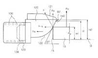
Translated fromKorean도 1은 본 발명에 따른 디스크 드라이브의 디스크 척킹장치를 도시한 사시도이다.1 is a perspective view showing a disk chucking device of a disk drive according to the present invention.
도 2는 본 발명에 따른 디스크 드라이브의 디스크 척킹장치를 도시한 종단면도이다.2 is a longitudinal sectional view showing a disk chucking apparatus of a disk drive according to the present invention.
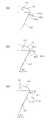
도 3(a)(b)는 본 발명에 따른 디스크 드라이브의 디스크 척킹장치에 채용되는 척핀을 도시한 사시도이다.Figure 3 (a) (b) is a perspective view showing a chuck pin employed in the disk chucking device of the disk drive according to the present invention.
도 4는 본 발명에 따른 디스크드라이브의 디스크 척킹장치를 도시한 상세도이다.4 is a detailed view showing the disk chucking apparatus of the disk drive according to the present invention.
도 5는 본 발명에 따른 디스크 드라이브의 디스크 척킹장치에서 디스크의 탈착시 발생되는 탈착력과 탄성력의 상관관계를 도시한 구성도이다.5 is a block diagram showing a correlation between the detachment force and the elastic force generated when the disc is detached in the disc chucking apparatus of the disc drive according to the present invention.
도 6(a)(b)(c)는 본 발명에 따른 디스크 드라이브의 디스크 척킹장치에 다양하게 채용되는 걸림부의 구성도이다.6 (a), (b) and (c) are configuration diagrams of various engaging portions employed in the disk chucking apparatus of the disk drive according to the present invention.
도 7(a)(b)(c)는 본 발명에 따른 디스크 드라이브의 디스크 척킹장치에서 디스크를 장착하는 작업순서도이다.7 (a), (b) and (c) are flowcharts showing the operation of mounting a disk in the disk chucking apparatus of the disk drive according to the present invention.
도 8(a)(b)(c)는 본 발명에 따른 디스크 드라이브의 디스크 척킹장치에서 디스크를 탈착하는 작업순서도이다.8 (a), (b) and (c) are flowcharts illustrating the operation of detaching a disk from the disk chucking apparatus of the disk drive according to the present invention.
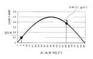
도 9는 수학식 3의 sinθ×cosθ 와 하부코너스프, 걸림부의 각도와의 상관관계를 도시한 그래프이다.FIG. 9 is a graph showing a correlation between sinθ × cosθ in
도 10은 하부코너슬로프의 각도변화에 따라 디스크와 척핀이 서로 접하는 접점위치가 변화하는 상태도이다.10 is a state diagram in which the contact position of the disk and the chuck pin contact with each other according to the change in the angle of the lower corner slope.
도 11은 종래 디스크드라이브의 디스크 척킹장치의 평면도이다.11 is a plan view of a disk chucking apparatus of a conventional disk drive.
* 도면의 주요부분에 대한 부호의 설명 *Explanation of symbols on the main parts of the drawings
100 : 디스크 척킹장치101 : 모터100: disk chucking device 101: motor
110 : 척베이스112 : 배치부110: Chuck Base 112: Placement
113 : 받침대114 : 절개부113: pedestal 114: incision
115 : 내주보스116,124 : 조립턱115: inner boss 116,124: assembly jaw
120 : 척핀121 : 상부코너슬로프120: chuck pin 121: upper corner slope
122 : 하부코너슬로프130 : 스프링부재122: lower corner slope 130: spring member
140 : 걸림부150 : 탄성편140: engaging portion 150: elastic piece
본 발명은 디스크 드라이브에 구비되어 디스크를 척킹하는 장치에 관한 것으로, 보다 상세히는 디스크를 척베이스에 삽입하는데 소요되는 장착력에 관계없이 디스크가 분리되는데 소요되는 탈착력을 증가시켜 디스크 드라이브의 작동중 척베이스로부터 디스크가 분리이탈되는 것을 방지함과 동시에 자동조심성능을 향상시킬 수 있는 디스크 드라이브의 디스크 척킹장치에 관한 것이다.The present invention relates to an apparatus for chucking a disk provided in a disk drive, and more particularly, to increase the detachment force required to separate the disk regardless of the mounting force required to insert the disk into the chuck base during operation of the disk drive. The present invention relates to a disk chucking device of a disk drive that can prevent the disk from being separated from the chuck base and improve the automatic watch performance.
일반적으로 디스크 드라이브는 본체를 이루는 데크 베이스와, 디스크를 상기 데크 베이스로 로딩 및 언로딩시키는 수단과, 상기 디스크 로딩 및 언로딩수단에 의해 로딩된 디스크를 소정의 속도로 회전시키는 수단 및 상기 회전수단에 의해 회전되는 디스크의 반경으로 이송하면서 디스크의 기록면에 정보를 기록 및/또는 재생하는 수단을 포함한다. 여기서, 상기 디스크는 트레이에 탑재되어 로딩 및 언로딩 될 수 있으며, 캐디나 카트리지에 수납되어 데크 베이스의 내부로 인입 및 인출될 수 있는 등 여러 가지 타입의 디스크 드라이브가 알려져 있다.Generally, a disc drive includes a deck base constituting a main body, means for loading and unloading a disc into the deck base, means for rotating the disc loaded by the disc loading and unloading means at a predetermined speed, and the rotating means. And means for recording and / or reproducing information on the recording surface of the disk while transferring to the radius of the disk to be rotated by the disk. Here, various types of disk drives are known, such that the disks can be loaded into and unloaded from a tray, accommodated in a caddy or a cartridge, and can be inserted into and removed from the deck base.
그리고, 상기 디스크를 회전시키는 수단으로는 스핀들 모터가, 디스크의 기록면에 정보를 기록 및/또는 재생하는 수단으로는 픽업 유니트가 통상적으로 채용된다.As a means for rotating the disk, a spindle motor is usually employed, and a pickup unit is usually employed as a means for recording and / or reproducing information on the recording surface of the disk.
이러한 디스크드라이브에서는 스핀들모터의 회전구동력에 의하여 일방향 회전되는 디스크의 안전성을 확보하기 위해서 디스크가 고정되는 척킹장치가 구비되며, 상기 디스크 척킹장치의 척킹성능은 매우 중요한 핵심기술이다.Such a disk drive is provided with a chucking device to which the disk is fixed in order to secure the safety of the disk rotated in one direction by the rotational driving force of the spindle motor, the chucking performance of the disk chucking device is a very important core technology.
도 11은 종래 디스크드라이브용 디스크 척킹장치의 구성도로서, 종래 디스크척킹장치(1)는 도시한 바와같이, 모터의 구동력에 의해 회전되는 턴테이블이나 회전케이스(9)의 상부면에 고정설치되어 디스크(10)의 중심공(15)이 삽입되는 척베이스(2)를 갖추고, 상기 척베이스(2)에는 그 외주를 따라 절개된 복수개의 배치부(2a)마다 전후이동가능하게 배치되는 척핀(3)을 갖추며, 상기 척베이스(2)의 배치부(2a)사이마다 형성되어 상기 척베이스(2)에 장착된 디스크(10)의 중심공(15)을 자체탄성력으로 탄력지지하는 탄성편(4)을 갖추는 한편, 상기 척핀(3)의 후단에서 전방으로 탄력지지하는 스프링부재(5)로 구성된다. 도 8에서 미설명 부호 8은 상기 모터가 탑재되는 기판이다.11 is a configuration diagram of a disk chucking apparatus for a conventional disk drive, the conventional disk chucking apparatus 1 is fixed to the upper surface of the turntable or rotating
이러한 구성을 갖는 종래의 디스크 척킹장치(1)를 이용하여 디스크(10)를 삽입하는 장착방법은 상기 척베이스(2)의 상방으로부터 디스크(10)가 직하방으로 눌려지면, 상기 척베이스(2)의 외경은 상기 디스크(10)의 중심공(15)의 내경보다 작은 반면에 상기 척베이스(2)에 조립된 척핀(3)의 선단이 외주방향으로 돌출되어 있기 때문에, 상기 중심공(15)의 내주면 에지부가 상기 척핀(3)에 간섭되어 접해지게 된다.The mounting method for inserting the
그리고, 상기 척핀(3)의 선단상부면은 하방으로 완만하게 경사진 테이퍼면으로 형성되어 있기 때문에, 직하방으로 가해지는 디스크(10)의 장착력에 의해 상기 척핀(3)은 상기 스프링부재(5)를 압축시키면서 후방으로 밀려지게 됨과 동시에 상기 탄성편(4)도 후방으로 밀려진다.In addition, since the upper end surface of the
이어서, 상기 디스크(10)가 바닥면에 장착된 환고리형의 러버재(6)의 상부면에 접해지면, 압축시 스프링부재(5)의 탄성복원력에 의해 전방으로 원상복귀되려고 하는 척핀(3)과 탄성편(4)에 의해서 상기 디스크(10)는 장착되는 것이다.Subsequently, when the
반면에, 상기 디스크 척킹장치(1)에 장착된 디스크(10)를 분리하는 탈착작업은 상기 디스크(10)가 척베이스(2)에 삽입된 상태에서 상기 디스크(10)가 상방으로 들어올려지면, 상기 디스크(10)의 중심공(15)의 내주면 에지부가 접하는 척핀(3)의 선단 하부면도 상방으로 완만하게 경사진 테이퍼면으로 형성되어 있기 때문에, 직상방으로 가해지는 디스크(10)의 탈착력에 의해 상기와 마찬가지로 상기 척핀(3)은 스프링부재(5)를 압축시키면서 후방으로 밀려지게 된다.On the other hand, the detachment operation of detaching the
그리고, 상기 디스크(10)가 척킹장치(1)로부터 완전히 분리되면, 자유로워져 복원되는 스프링부재(5)의 탄성복원력에 의해서 상기 척핀(3)은 전방으로 복귀되어 척베이스(2)의 외부면으로 선단이 돌출되고, 상기 디스크(10)의 중심공(15)의 중심과 상기 턴테이블(9)의 회전중심이 서로 일치되도록 상기 디스크(10)의 중심공(15)의 내주면에 접하여 내측으로 탄성변형된 탄성편(4)도 자체탄성력에 의해서 원상태로 복귀된다.Then, when the
이러한 디스크 척킹장치(1)에서 상기 디스크(10)를 척베이스(2)에 삽입하는데 소요되는 장착력은 사용자가 신속하고, 간편하게 디스크(10)를 척베이스(2)에 장착할 수 있도록 최소한의 힘인 150 내지 200gf으로 작게 설정하는 반면에, 디스크(10)를 척베이스(2)로부터 분리하는데 소요되는 탈착력은 스핀들모터의 회전구동력에 의해 턴테이블(9)상의 디스크(10)가 이탈되거나 슬립되지 않도록 300gf이상 그리고 고의로 이탈시 과도한 하중을 막기위한 목적으로 600gf이하의 범위내에서 설정하는 것이 가장 이상적이다.In the disc chucking apparatus 1, the mounting force required to insert the
그러나, 종래의 디스크 척킹장치(1)에서 장착력을 작게 하기 위해 최적의 기준값인 150 내지 200gf 보다 작은 탄성력을 갖는 스프링부재(5)를 채용하는 경우, 작아진 장착력만큼 상대적으로 척베이스(2)에 장착된 디스크(10)를 고정하는 고정 력이 작아지면서 비례적으로 탈착력도 사전에 설정된 일정범위이하로 작아지기 때문에, 모터의 회전구동시 디스크(10)가 이탈되거나 회전중 슬립되는 작동불량이 빈번하게 발생하였다.However, in the case of employing the
반대로, 상기 스프링부재(5)의 탄성력을 최적의 기준값보다 크게 하는 경우, 장착력과 더불어 탈착력도 비례적으로 증가되기 때문에, 척베이스(2)로부터 디스크(10)가 이탈되고, 슬립되는 현상을 예방할 수 있는 잇점이 있는 반면에, 사용자가 척베이스(2)에 디스크(10)를 부드럽게 장착하는 작업이 곤란해지면서 사용상 매우 불편해지는 문제점이 발생하였다.On the contrary, when the elastic force of the
그리고, 상기 스프링부재(5)의 불균일한 탄성력에 의해 척베이스(2)에 적어도 3개이상 구비되는 척핀(3)중 일부에만 탄성력이 크게 걸리는 경우, 디스크장착시 상기 척핀(3)이 척베이스(2)에 장착되는 디스크(10)의 중심공(15)을 통과하지 못하고 중심공(15)의 내주면에 접하여 걸리는 하프척킹(half chucking)현상이 빈번하게 발생되며, 이로 인해 상기 스프링부재(5)가 상대적으로 큰 탈착력을 갖더라도 디스크회전중 디스크(10)가 이탈되는 작동불량을 유발하였다.When the elastic force is largely applied to only a part of the
또한, 상기 척핀(3)에 의한 탈착력의 영향력이 커지면, 상기 스프링부재(5)의 탄성력도 상대적으로 커져야만 하고, 상기 스프링부재(5)의 탄성력이 커지면 복수개의 척핀(3)을 전방으로 탄력지지하는 복수개의 스프링부재(5)간의 편차도 상대적으로 증대되고, 탄성편(4)의 탄성력보다 커지게 된다. 이러한 경우, 디스크(10) 장착시 상기 턴테이블(9)의 중심과 상기 디스크(10)의 중심공(15)의 중심을 서로 일치시키는 자동조심을 수행하는 탄성편(4)의 자동조심성능및 역활이 감소되거나 상실되기 때문에, 픽업유니트(미도시)로서 디스크의 기록면에 정보를 기록 및/또는 재생하는 작업이 정밀하고, 원활하게 수행하는 것이 곤란하였다.In addition, when the influence of the detachment force by the chuck pin (3) increases, the elastic force of the spring member (5) must also be relatively large, when the elastic force of the spring member (5) increases, the plurality of chuck pins (3) to the front The deviation between the plurality of
이와 더불어, 상기 척핀(3)을 스프링부재(5)와 더불어 척베이스(2)에 조립하는 작업시 상기 스프링부재(5)가 갖는 큰 탄성력에 의해 작업자가 상기 척베이스(2)와 상기 척핀(3)사이에 스프링부재(5)를 조립하는데 걸리는 작업부하도 상대적으로 점차 커지고, 이로 인해 조립작업성을 저하시키는 문제점이 있었다.In addition, when the assembly of the chuck pin (3) to the chuck base (2) together with the spring member (5) by the large elastic force of the spring member (5) the operator has the chuck base (2) and the chuck pin ( 3) the work load that is required to assemble the spring member (5) between the relatively increased gradually, thereby causing a problem of lowering the assembly workability.
따라서, 본 발명은 상기한 문제점을 해결하기 위해 안출한 것으로, 그 목적은 디스크를 척베이스에 삽입하는 장착력에 영향을 전혀 주지 않으면서 디스크의 탈착력을 향상시켜 구동중 디스크의 이탈및 슬립현상을 예방하고, 탄성편에 의한 자동조심기능을 향상시키며, 조립부품의 조립작업성을 높일 수 있는 디스크 드라이브의 디스크 척킹장치를 제공하고자 한다.
Accordingly, the present invention has been made to solve the above problems, and its object is to improve the detachment force of the disc without affecting the mounting force for inserting the disc into the chuck base, thereby causing the disc to slip and slip during operation. It is to provide a disk chucking device of a disk drive that can prevent, improve the self-aligning function by the elastic piece, and can increase the assembly workability of the assembly.
상기한 목적을 달성하기 위한 기술적인 수단으로서, 본 발명은As a technical means for achieving the above object, the present invention
모터의 회전구동력에 의해 일방향 회전구동되는 디스크를 척킹하는 장치에 있어서,In the device for chucking the disk driven in one direction by the rotational driving force of the motor,
상기 디스크의 중심공이 대응삽입되고, 외주를 따라 복수개의 배치부가 절개형성된 척베이스;A chuck base in which a center hole of the disk is correspondingly inserted and a plurality of disposition portions are formed along the outer circumference thereof;
상기 배치부마다 반경방향으로 왕복이동가능하게 배치되고, 선단 상,하부면에 상,하부코너슬로프가 각각 형성된 척핀;A chuck pin disposed radially reciprocally in each of the arrangement parts, and having upper and lower corner slopes formed on upper and lower surfaces of the front end, respectively;
상기 척핀을 전방으로 탄력지지하도록 상기 척핀과 상기 척베이스사이에 조립되는 복수개의 스프링부재 ; 및A plurality of spring members assembled between the chuck pin and the chuck base to elastically support the chuck pin forward; And
상기 척베이스에 장착된 디스크의 중심공의 상단모서리가 대응하여 걸리도록 상기 척핀의 선단 하부면에 형성된 하부코너슬로프에 원주방향으로 적어도 한개 이상 함몰형성되는 걸림부를 포함함을 특징으로 하는 디스크 드라이브의 디스크 척킹장치를 마련함에 의한다.At least one recessed portion formed in the circumferential direction of the lower corner slope formed on the lower end of the chuck pin so that the upper edge of the center hole of the disk mounted on the chuck base correspondingly; By providing a disk chucking device.
바람직하게는 상기 척베이스의 외부면에는 상기 배치부사이마다 절개부를 절개형성하고, 상기 절개부마다 상기 디스크의 중심공의 내주면과 선단외부면이 자체탄성력으로 탄력지지되는 자동조심용 탄성편을 일체로 형성한다.Preferably, the outer surface of the chuck base is formed incision between each of the placement portion, the inner peripheral surface and the outer surface of the front end of the center hole of the disk for each of the incision integrally self-aligning elastic piece for elastic support Form.
바람직하게는 상기 걸림부의 형성높이는 상기 디스크의 하부면이 접하는 바닥면을 기준으로 하여 판두께와 대응하는 높이보다는 높고, 상기 척핀의 상부코너슬로프와 하부코너슬로프가 서로 만나는 최선단에 대응하는 높이보다는 낮게 구비된다.Preferably, the forming height of the engaging portion is higher than the height corresponding to the plate thickness on the basis of the bottom surface in contact with the lower surface of the disk, and than the height corresponding to the uppermost end of the upper corner slope and the lower corner slope of the chuck pin to meet each other. It is provided low.
바람직하게는 상기 걸림부는 상기 디스크의 상부면과 대응하여 수평한 수평면과, 상기 하부코너슬로프와 동일한 경사각도로 경사진 경사면으로 이루어진다.Preferably, the locking portion comprises a horizontal horizontal plane corresponding to the upper surface of the disk and an inclined surface inclined at the same inclination angle as the lower corner slope.
바람직하게는 상기 걸림부는 상기 디스크의 상부면과 대응하여 수평한 수평면과, 상기 디스크의 중심공내주면과 대응하여 수직한 수직면으로 이루어진다.Preferably, the locking portion comprises a horizontal horizontal surface corresponding to the upper surface of the disk, and a vertical vertical surface corresponding to the inner circumferential surface of the central hole of the disk.
바람직하게는 상기 걸림부는 상기 디스크의 상부면과 대응하여 상방으로 일정각도 경사진 경사면과, 상기 디스크의 중심공 내주면과 대응하여 수직한 수직면으로 이루어진다.Preferably, the locking portion comprises an inclined surface inclined upward at an angle corresponding to the upper surface of the disk, and a vertical surface perpendicular to the inner circumferential surface of the central hole of the disk.
바람직하게는 상기 걸림부는 상기 디스크의 상부면과 대응하여 상방으로 일정각도 경사진 경사면과, 상기 하부코너슬로프와 동일한 각도로 경사진 경사면으로 이루어진다.Preferably, the locking portion includes an inclined surface that is inclined upward at an angle corresponding to the upper surface of the disk, and an inclined surface that is inclined at the same angle as the lower corner slope.
바람직하게는 상기 하부코너슬로프는 50 내지 70°의 경사각도로 형성된다.Preferably, the lower corner slope is formed at an inclination angle of 50 to 70 degrees.
바람직하게는 상기 디스크의 상부면과 대응하여 상방으로 경사지는 걸림부의 경사면은 15°이하의 경사각도로 형성된다.Preferably, the inclined surface of the engaging portion inclined upwardly corresponding to the upper surface of the disk is formed at an inclination angle of 15 degrees or less.
바람직하게는 상기 척베이스의 외주면에는 상기 디스크의 하부면이 받쳐지는 받침대가 돌출형성되고, 상기 척핀과 대응하는 받침대에는 상기 하부코너슬로프의 외부면과 외접하는 만곡부를 형성한다.Preferably, the outer circumferential surface of the chuck base is protruded to support the lower surface of the disk, and the pedestal corresponding to the chuck pin forms a curved portion that is external to the outer surface of the lower corner slope.
이하, 본 발명에 대해서 보다 상세히 설명한다.Hereinafter, the present invention will be described in more detail.
도 1은 본 발명에 따른 디스크 드라이브의 디스크 척킹장치를 도시한 사시도이고, 도 2는 본 발명에 따른 디스크 드라이브의 디스크 척킹장치를 도시한 종단면도이며, 도 3(a)(b)는 본 발명에 따른 디스크 드라이브의 디스크 척킹장치에 채용되는 척핀을 도시한 사시도이고, 도 4는 본 발명에 따른 디스크드라이브의 디스크 척킹장치를 도시한 상세도이다.1 is a perspective view showing a disk chucking device of a disk drive according to the present invention, Figure 2 is a longitudinal sectional view showing a disk chucking device of a disk drive according to the present invention, Figure 3 (a) (b) is the present invention Figure 4 is a perspective view showing a chuck pin employed in the disk chucking device of the disk drive according to, Figure 4 is a detailed view showing the disk chucking device of the disk drive according to the present invention.
본 발명의 장치(100)는 도 1 내지 4에 도시한 바와같이, 모터(101)의 회전구동력에 의해 회전대상물인 디스크(10)를 일방향 회전구동시키는 디스크 드라이브에 디스크(10)를 장착하는데 소요되는 힘인 장착력(FI)에 전혀 영향을 주지 않으면서 척베이스(110)에 장착된 디스크(10)를 분리하는데 소요되는 힘인 탈착력(FO)만을 증가시킬 수 있는 것으로써, 이러한 장치(1)는 척베이스(110), 척핀(120), 스프링부재(130)및 걸림부(140)로 구성된다.1 to 4, the
즉, 디스크(10)의 중심에 원형으로 관통형성된 중심공(15)이 삽입되는 척베이스(110)는 모터(101)의 회전구동축(102)의 중심과 동일한 축상에 몸체중심이 조립되어 모터구동시 상기 디스크(10)와 더불어 일방향 회전되는 회전구조물이다.That is, the
이러한 척베이스(110)는 상기 모터(101)의 구동시 고정자(101a)에 대하여 일방향 회전되는 회전자인 회전자케이스(101b)의 상부면에 구비되거나, 상기 회전자케이스(101b)의 상부면에 조립되는 별도의 턴테이블(미도시)에 구비될 수도 있다.The
상기 척베이스(110)가 회전자케이스(101b)에 구비되는 경우, 상기 척베이스(110)는 몸체중앙부에 상기 회전자케이스(101b)의 상부면 중심으로부터 직상부로 일정높이 연장된 중심축부(108)가 삽입되는 중공형 내주보스(115)를 관통형성하고, 외부면에는 외주를 따라 등간격의 각도를 두고 적어도 적어도 3개이상의 배치부(112)가 반경방향으로 절개형성된다.When the
여기서, 상기 모터(101)의 회전구동축(102)은 상기 척베이스(110)의 내주보스(115)와 조립되는 중공형 중심축부(108)내로 삽입된다. 이에 따라, 상기 회전자 케이스(101b)의 중심축부(108)와 척베이스(110)의 내주보스(115)의 중심은 상기 모터(101)의 회전구동축(102)과 동일한 수직축상에 배치되어 상기 모터(101)의 구동시 상기 척베이스(110)에 장착된 디스크(10)를 일방향으로 회전시키게 되는 것이다.Here, the
그리고, 상기 회전자케이스(101b)의 외주 근방에는 상기 척베이스(110)에 장착되는 디스크(10)의 하부면과 상부면이 면접되어 모터구동에 의한 디스크구동시 디스크의 슬립현상을 방지할 수 있도록 마찰력을 발생시키는 환고리형 마찰재(107)가 장착되어 있다.In addition, a lower surface and an upper surface of the
또한, 상기 척핀(120)은 상기 디스크(10)의 장착및 탈착시마다 상기 중심공(15)의 내주면 상,하부모서리와 간섭되어 직하방으로 가해지는 장착력(FI) 또는 직상방으로 가해지는 탈착력(Fo)에 의해서 반경방향으로 후진안내되도록 상기 척베이스(110)의 상부면에 외주를 따라 등각도로 절개형성된 배치부(112)마다 왕복이동가능하게 조립되는 작동부재이다.In addition, the
이러한 척핀(120)은 상기 디스크(10)의 장착시 중심공(15)의 하단이 간섭되는 선단 상부면에 전방으로 갈수록 서서히 완만하게 하방으로 경사지는 상부코너슬로프(121)가 형성되고, 상기 디스크(10)의 탈착시 중심공(15)의 상단이 간섭되는 선단 하부면에는 전방으로 갈수록 상부로 완만하게 서서히 경사지는 하부코너슬로프(122)가 형성되는 한편, 상기 상부코너슬로프(121)가 시작되는 몸체상부면에는 상기 척베이스(110)의 배치부(112)를 따라 왕복안내이동이 원활하게 이루어지도록 상기 배치부(112)으로 끼워지는 안내홈(129)이 길이방향으로 길게 형성된다.The
상기 배치부(112)에 조립되는 척핀(120)의 몸체후단에는 상기 배치부(112)로부터의 이탈이 곤란하도록 상기 배치부(112)에 걸리는 날개부(123a)(123b)가 좌우방향으로 연장되며, 상기 날개부(123a)(123b)사이에는 상기 스프링부재(130)의 선단이 끼워져 위치고정되는 조립턱(124)이 돌출형성되어 있다.At the rear of the body of the
또한, 상기 척핀(120)이 장착되는 척베이스(110)의 외부면에는 상기 배치부(112)사이마다 절개부(114)를 등간격을 두고 절개형성하고, 상기 절개부(114)마다 상기 척베이스(110)의 장착시 선단이 반경방향으로 탄성변형된후 상기 디스크(10)의 중심공(15)의 내주면에 외부면이 자체탄성력으로 탄력지지되도록 대략적으로 'ㄴ'단면상을 갖는 자동조심용 탄성편(150)을 일체로 형성한다.In addition, the outer surface of the
이러한 자동조심용 탄성편(150)은 원주방향으로 등간격을 두고 구비되는 척핀(120)사이마다 형성되어 상기 척베이스(110)에 장착되는 디스크(10)의 중심과 상기 척베이스(110)의 회전중심이 동일한 수직축상에 위치되도록 상기 디스크(10)의 중심공(15)내주면을 탄력지지한다.The self-aligning
그리고, 상기 스프링부재(130)는 상기 척베이스(110)에 구비되는 척핀(120)을 전방으로 항상 탄력지지하도록 일정크기의 탄성력을 구비하여 상기 척핀(120)과 상기 척베이스(110)의 내주보스(115)사이마다 배치되는 코일상의 탄성체이다.In addition, the
이러한 스프링부재(130)의 일단은 상기 척핀(120)의 후단에 일체로 돌출형성되는 조립턱(124)에 삽입되어 고정되고, 타단은 상기 내주보스(115)의 외부면에 일체로 돌출형성되는 또다른 조립턱(116)에 삽입되어 고정된다.One end of the
한편, 상기 디스크(10)를 척베이스(110)로부터 분리하는데 소요되는 힘인 탈착력(Fo)을 증가시키는 걸림부(140)는 상기 척베이스(110)에 장착된 디스크(10)의 탈착시 중심공(15)의 상단모서리가 대응하여 걸리도록 상기 척핀(120)의 선단 하부면에 형성된 하부코너슬로프(122)에 원주방향으로 적어도 한개 이상 구비된다.On the other hand, the engaging
이러한 걸림부(140)는 상기 척베이스(110)에 복수개 구비되는 척핀(120)의 하부코너슬로프(122)마다 동일하게 형성되며, 그 형성높이(H)는 도 5에 도시한 바와같이, 상기 척베이스(110)에 장착된 디스크(10)의 하부면이 접하는 바닥면(G)을 기준으로 하여 판두께와 대응하는 높이(H1)보다는 높고, 상기 척핀(120)의 상부코너슬로프(121)와 하부코너슬로프(122)가 서로 만나는 최선단에 대응하는 높이(H2)보다는 낮게 구비하는 것이 바람직하다.The engaging
이에 따라, 상기 척베이스(110)에 장착된 디스크(10)의 중심공(15)의 내주상단모서리는 상기 척핀(120)에 형성된 걸림부(140)보다 항상 낮은 높이에 위치되어 상기 디스크(10)의 탈착시 상기 걸림부(140)에 걸리면서 걸림력을 유도하여 탈착력(FO)을 증가시킬 수 있는 것이다.Accordingly, the inner circumferential upper edge of the
이때, 상기 척베이스(110)에 장착되는 디스크(10)는 이를 제조하는 회사의 기술수준에 따라 판두께의 차이가 다양하게 나타나며, 통상 0.6 내지 1.5mm 의 판두께를 갖는다.At this time, the
또한, 상기 디스크(10)의 탈착시 중심공(15)의 내주상단모서리가 접하여 걸리도록 하부코너슬로프(122)에 함몰형성되는 걸림부(140)는 도 4에 도시한 바와같 이, 상기 디스크(10)의 상부면과 대응하여 수평한 수평면(141)과, 상기 하부코너슬로프(122)와 동일한 경사각도로 경사진 경사면(142)으로 이루어지도록 함몰형성된다.In addition, as shown in FIG. 4, the engaging
상기 걸림부(140a)는 도 6(a)에 도시한 바와같이, 상기 디스크(10)의 상부면과 대응하여 수평한 수평면(141a)과, 상기 디스크(10)의 중심공(15)내주면과 대응하여 수직한 수직면(142a)으로 이루어지도록 함몰형성되어도 좋다.As illustrated in FIG. 6A, the locking
그리고, 상기 걸림부(140b)는 도 6(b)에 도시한 바와같이, 상기 디스크(10)의 상부면과 대응하여 상방으로 일정각도 경사진 경사면(141b)과, 상기 디스크(10)의 중심공(15)내주면과 대응하여 수직한 수직면(142b)으로 이루어지도록 함몰형성되어도 좋다.And, as shown in Figure 6 (b), the engaging
또한, 상기 걸림부(140c)는 도 6(c)에 도시한 바와같이, 상기 디스크(10)의 상부면과 대응하여 상방으로 일정각도 경사진 경사면(141c)과, 상기 하부코너슬로프(122)와 동일한 각도로 경사진 경사면(142c)으로 이루어지도록 함몰형성되어도 좋다.In addition, as shown in FIG. 6C, the locking
여기서, 상기 척핀(120)의 선단상부면에 형성되는 상부코너슬로프(121)는 디스크탈착시 디스크(10)의 중심공(15)이 접하는 하부코너슬로프(122)의 경사각도보다 낮게 형성된다.Here, the
한편, 상기 디스크(10)의 착탈시 그 중심공의 내주면이 접하는 하부코너슬로프(122)는 스프링부재(130)의 탄성력의 변화없이 디스크 회전구동시 슬립토크를 높일 수 있도록 50° 내지 70°의 경사각도(θ1)로 구비되는 것이 바람직하며, 상기 디스크(10)의 상부면과 대응하여 상방으로 경사지는 걸림부(140b)(140c)의 각 경사면(141b)(141c)은 스프링부재(130)의 탄성력(130)의 변화없이 탈착력(FO)을 높일 수 있도록 15 °이하의 경사각도(θ2)로 형성하는 것이 바람직하다.On the other hand, the
상기한 구성을 갖는 본 발명의 디스크 척킹장치(100)를 이용하여 척베이스(110)에 디스크(10)를 장착하는 작업은 도 7(a)에 도시한 바와같이, 척베이스(110)의 직상부에 장착하고자 하는 디스크(10)를 배치하여 상기 척베이스(110)상에 디스크(10)의 중심공(15)을 일치시킨 상태에서, 사용자가 상기 디스크(10)를 직하방으로 눌러 장착하게 된다.Mounting the
이때, 상기 척베이스(110)의 외경은 상기 디스크(10)의 중심공(15)의 내경보다 작지만 상기 척베이스(110)의 배치부(112)에 구비된 척핀(120)이 반경방향으로 돌출되어 있기 때문에, 상기 중심공(15)의 하단은 상기 척핀(120)의 선단에 형성된상부코너슬로프(121)에 간섭된다.At this time, the outer diameter of the
연속하여, 도 7(b)에 도시한 바와같이, 상기 디스크(10)가 직하방으로 하강되는 외력인 장착력(FI)에 의해서 복수개의 척핀(120)은 동시에 척베이스(110)의 배치부(112)를 따라 후진되고, 그 선단이 척베이스(110)내로 삽입됨과 동시에 상기 척핀(120)이 후진이동되는 이동량만큼 상기 척핀(120)과 척베이스(110)의 내주보스(115)사이에 구비된 스프링부재(130)는 압축되어 탄성복원력을 발생시킨다.Subsequently, as shown in FIG. 7B, the plurality of chuck pins 120 are disposed at the same time by the mounting force FI , which is an external force of the
그리고, 상기 척베이스(110)의 외주면에는 상기 디스크(10)의 하부면이 면접 하여 받쳐지는 받침대(113)가 돌출형성되고, 상기 척핀(120)과 대응하는 받침대(113)에는 상기 하부코너슬로프(122)의 외부면과 외접하도록 만곡부(113a)를 형성하고 있기 때문에, 상기 척핀(120)은 장착력에 의해서 선단이 상기 배치부(112)내로 삽입됨과 동시에 하방으로 선회된다.In addition, a
도 7(c)에 도시한 바와같이, 상기 디스크(10)의 중심공(15)의 내주면이 상기 상부코너슬로프(121)의 최선단을 통과하면, 상기 척핀(120)을 전방으로 탄력지지하는 스프링부재(130)의 탄성복원력에 의해 디스크(10)를 위치고정할 수 있는 것이다.As shown in FIG. 7C, when the inner circumferential surface of the
한편, 상기 디스크 척킹장치(100)의 척베이스(110)로부터 디스크(10)를 분리하는 탈착작업은 도 8(a)(b)(c)에 도시한 바와같이, 사용자가 상기 척베이스(2)에 장착된 디스크(10)를 상방으로 외력인 탈착력(FO)을 가하여 들어올리면, 상기 디스크(10)의 중심공(15)의 내주면 상단모서리와 척핀(120)의 선단 하부면에는 상방으로 완만하게 경사진 하부코너슬로프(122)가 형성되어 있기 때문에, 장착시와 마찬가지로 상기 척핀(120)은 스프링부재(130)를 압축시키면서 후방으로 밀려지게 된다.On the other hand, the detachment operation of separating the
그리고, 상기 하부코너슬로프(122)에 접하여 상승되던 디스크(10)의 중심공 (15)내주면 상단모서리가 상기 하부코너슬로프(122)에 형성된 걸림부(140)에 위치되어 걸리면, 상기 걸림부(140)에서 걸림력을 발생시켜 탈착력(FO)을 증대시키게 된다. 이와 동시에, 상기 걸림부(140)가 형성되는 하부코너슬로프(122)의 경사각도( θ1)의 변화에 의하여 탈착력(FO)및 슬립토크를 가변시킬 수 있으며, 상기 걸림부(140)에서 발생되는 걸림력은 상기 걸림부(140)의 경사각도(θ2)의 변화에 따라 가변시킬 수 있다.When the upper edge of the inner circumferential surface of the
즉, 종래 척핀에는 디스크(10)가 걸리는 걸림부가 형성되어 있지 않기 때문에, 걸림력이 '0' 이고, 탈착력(Fo)은 단지 스프링부재(130)의 탄성력(FS)에 의해서 결정되었지만, 본 발명의 척핀(120)에는 도 5에 도시한 바와같이, 탈착시 디스크(10)가 자연스럽게 걸리는 걸림부(140)가 형성되어 있기 때문에, 스프링부재(140)의 탄성력변화없이 탈착력(FO)을 증대시킬 수 있으며, 상기 걸림부(140)에서 발생되는 걸림력은 상기 걸림부(140)의 각도변화에 따라 무한대까지 변화시킬 수 있다.That is, because the conventional chuck pin does not have a locking portion for engaging the
도 5에 도시한 바와같이, 상기 디스크(10)를 척베이스(110)로부터 분리하는데 발생되는 합력(F)은 하기 수학식 1에 의해서 얻어지며, 이때 발생되는 스프링부재(130)의 탄성력(FS)은 하기 수학식 2와 같이 얻어짐에 따라, 상기 디스크(10)의 탈착력(FO)과 상기 스프링부재(130)의 탄성력(FS)은 하기 수학식 3과 같은 상관관계를 갖게 된다.As shown in FIG. 5, the force F generated to separate the


이러한 경우, 상기 스프링부재의 탄성력을 그대로 유지한 상태에서 탈착력을 증대시키는 방법은 도 9에 도시한 바와같이, 상기 하부코너슬로프(122)의 경사각도(θ1)와 상기 걸림부(120)의 경사각도(θ2)의 각도변화에 대하여 수학식 3의 sinθ×cosθ 가 변화하기 때문에, 상기 하부코너슬로프(122)의 경사각도(θ1)를 45°보다는 크고, 90°보다는 작은 범위인 50° 내지 70°로 형성하는 것이 바람직하다.In this case, the method of increasing the detachment force while maintaining the elastic force of the spring member as shown in Figure 9, the inclination angle (θ1) of the
그리고, 본 발명의 척핀(120)에 형성되는 하부코너슬로프(122)의 경사각도(θ1)가 50° 내지 70°로 구성되면, 도 10에 도시한 바와같이, 디스크장착시 본 발명의 척핀(120)이 디스크(10)와 접하는 접점위치(P2)가 35° 또는 36°의 경사각도(α)를 갖는 척핀이 디스크(10)와 접하는 접점위치(P1)보다도 외측에 위치되기 때문에, 상기 척핀(120)에 의해서 후방으로 밀려지는 스프링부재(130)의 수축길이는 종래보다 길게 된다.Then, when the inclination angle θ1 of the
이러한 경우, 상기 스프링부재(130)는 하기 수학식 4에 의하여 일정한 상수(k)에 대하여 수축길이(x)가 길어지기 때문에 탄성복원력을 증대시켜 디스크회전구동시 디스크의 슬립토크를 높일 수 있는 것이다.In this case, the

한편, 상기 걸림부(140)의 경사각도(θ2)는 15°이하의 경사각도로 형성하면, 스프링부재(130)의 탄성력(FS)을 그대로 유지한 상태에서 수학식 3에서 sinθ×cosθ 의 값을 0.1 이하로 유지하여 탈착력(Fo)만을 높일 수 있는 것이다.On the other hand, when the inclination angle θ2 of the locking
그리고, 상기 디스크(10)가 척킹장치(100)로부터 완전히 분리되면, 자유로워져 복원되는 스프링부재(140)의 탄성복원력에 의해서 상기 척핀(120)은 전방으로 복귀되면서 척베이스(110)의 외부면으로 선단이 돌출되어 원상복귀됨과 동시에 탄성편(150)도 자체탄성력에 의해서 원상태로 복귀된다.In addition, when the
이때, 디스크(10)의 분리시 소요되는 힘인 탈착력(Fo)은 상기 걸림부(140)에 디스크(10)가 걸리면서 발생되는 걸림력에 의해 증대되기 때문에 디스크(10)의 삽입시 소요되는 힘인 장착력(FI)을 설계시 허용되는 범위내에서 최소값으로 설정할 수 있으며, 이러한 경우, 디스크장착력에 가장 큰 영향을 주는 스프링부재(130)의 탄성력을 상기 걸림부(140)가 형성되지 않은 종래보다 상대적으로 낮게 구비할 수 있다.At this time, the detachment force (Fo ) that is a force required when the
또한, 상기 디스크(10)의 중심공(15)의 내주면에는 상기 척핀(120)사이마다 형성된 탄성편(150)의 선단이 접하고, 상기 탄성편(150)은 방사방향으로 균일한 자체탄성력으로서 탄력지지됨과 동시에, 상기 탄성편(150)의 자동조심성능에 가장 큰 영향을 미치는 스프링부재(130)의 탄성력이 낮아지는 반면에 탄성편(150)의 영향력 이 커지기 때문에, 상기 탄성편(150)에 의해서 디스크(10)의 중심과 상기 척베이스(110)의 중심을 서로 일치시키는 자동조심성능을 종래에 비하여 높일 수 있는 것이다.In addition, the inner circumferential surface of the
한편, 80gf 탄성력을 갖는 스프링부재를 갖는 본 발명의 척킹장치(100)와 종래 척킹장치(1)에 각각 중심공(15)의 내경이 15mm 이고, 두께가 1.2t 인 디스크(10)를 장착하고, 탈착하는 작업시 발생되는 장착력, 탈착력및 슬립토크를 각각 측정하고, 하프척킹의 발생여부를 확인하고, 그 결과를 하기 표 1에 나타내었다.On the other hand, in the
상기 표 1에서 알 수 있듯이, 본 발명의 척킹장치(100)에서 디스크를 장착하는 장착력과 종래의 척킹장치(1)에서 디스크를 장착하는 장착력은 동일한 반면에, 디스크를 분리하는 탈착력은 걸림부(140)에 의해서 발생되는 걸림력에 의하여 종래대비 87% 상승되었고, 슬립토크도 상승됨을 확인할 수 있었다.As can be seen in Table 1, the mounting force for mounting the disk in the
상술한 바와 같은 본 발명에 따르면, 척베이스로부터의 디스크를 분리하는 탈착작업시 디스크의 중심공이 걸리어 걸림력을 발생시키도록 척핀의 선단하부면에 걸림부를 형성함으로서, 디스크를 척베이스에 삽입하는 장착력에 관계없이 탈착력을 증대시킬 수 있기 때문에, 모터의 회전구동시 디스크가 이탈되거나 회전중 슬립되는 작동불량을 예방할 수 있다.According to the present invention as described above, by inserting the disk into the chuck base by forming a locking portion on the lower end surface of the chuck pin so that the center hole of the disk is caught in the detachment operation of separating the disk from the chuck base to generate a locking force Since the detachment force can be increased irrespective of the mounting force, it is possible to prevent a malfunction of the disk that is dislodged or slips during rotation during rotation of the motor.
또한, 탈착력을 증대시킴과 동시에 장착력에 영향을 미치는 스프링부재의 탄성력을 최소한으로 줄여 장착력을 감소시킬 수 있기 때문에, 사용자가 척베이스에 디스크를 삽입하는 작업을 종래에 비하여 부드럽고, 간편하게 수행할 수 있고, 복수개의 척핀중 일부가 디스크의 중심공의 내주면에 불량하게 척킹되는 하프척킹현상을 예방할 수 있을 뿐만 아니라, 작업자가 척핀을 스프링부재와 더불어 척베이스에 조립하는 작업부하를 줄여 조립작업성을 향상시킬 수 있다.
In addition, since the mounting force can be reduced by minimizing the elastic force of the spring member affecting the mounting force while increasing the detachment force, the user inserts the disc into the chuck base smoothly and conveniently. It is possible to prevent the half chucking phenomenon in which some of the plurality of chuck pins are poorly chucked to the inner circumferential surface of the center hole of the disk, and also reduce the work load for the operator to assemble the chuck pins together with the spring member to the chuck base. Can improve the sex.
또한, 스프링부재의 탄성력이 감소되는 것에 의해 장착력이 감소된 만큼 탄성편에 의한 자동조심성능을 상대적으로 증대시킬 수 있기 때문에, 디스크의 중심공의 중심을 회전자케이스의 중심에 일치시키는 자동조심을 정밀하게 수행하여 디스크의 기록면에 정보를 기록 및/또는 재생하는 작업을 종래에 비하여 정밀하게 수행할 수 있다.
In addition, since the self-aligning performance by the elastic pieces can be relatively increased as the mounting force is reduced by reducing the elastic force of the spring member, the self-aligning to match the center of the center hole of the disc to the center of the rotor case. Operation to record and / or reproduce information on the recording surface of the disc can be performed more precisely than in the prior art.
본 발명은 특정한 실시예에 관련하여 도시하고 설명하였지만, 이하의 청구범위에 의해 마련되는 본 발명의 정신이나 분야를 벗어나지 않는 한도내에서 본 발명이 다양하게 개조 및 변화될수 있다는 것을 당업계에서 통상의 지식을 가진자는 용 이하게 알수 있음을 밝혀두고자 한다.While the invention has been shown and described with respect to specific embodiments thereof, it will be apparent to those skilled in the art that various changes and modifications can be made without departing from the spirit or scope of the invention as set forth in the claims below. I would like to clarify that knowledge can be easily understood.
Claims (10)
Translated fromKoreanPriority Applications (1)
| Application Number | Priority Date | Filing Date | Title |
|---|---|---|---|
| KR1020040020185AKR100576863B1 (en) | 2004-03-25 | 2004-03-25 | Disk Chucking Device of Disk Drive |
Applications Claiming Priority (1)
| Application Number | Priority Date | Filing Date | Title |
|---|---|---|---|
| KR1020040020185AKR100576863B1 (en) | 2004-03-25 | 2004-03-25 | Disk Chucking Device of Disk Drive |
Publications (2)
| Publication Number | Publication Date |
|---|---|
| KR20050095085A KR20050095085A (en) | 2005-09-29 |
| KR100576863B1true KR100576863B1 (en) | 2006-05-10 |
Family
ID=37275644
Family Applications (1)
| Application Number | Title | Priority Date | Filing Date |
|---|---|---|---|
| KR1020040020185AExpired - Fee RelatedKR100576863B1 (en) | 2004-03-25 | 2004-03-25 | Disk Chucking Device of Disk Drive |
Country Status (1)
| Country | Link |
|---|---|
| KR (1) | KR100576863B1 (en) |
Cited By (3)
| Publication number | Priority date | Publication date | Assignee | Title |
|---|---|---|---|---|
| KR100934052B1 (en) | 2006-11-16 | 2009-12-24 | 니혼 덴산 가부시키가이샤 | Chucking Mechanism, Brushless Motor and Disc Drive |
| KR100982846B1 (en)* | 2007-10-16 | 2010-09-16 | 니혼 덴산 가부시키가이샤 | Motor with chucking device and disk drive with motor |
| CN102034507A (en)* | 2009-10-07 | 2011-04-27 | 三星电机株式会社 | Disk chucking device and motor device having the same |
Families Citing this family (11)
| Publication number | Priority date | Publication date | Assignee | Title |
|---|---|---|---|---|
| KR100593922B1 (en)* | 2004-08-05 | 2006-06-30 | 삼성전기주식회사 | Disk Chucking Device of Disk Drive |
| JP2008092706A (en) | 2006-10-03 | 2008-04-17 | Nippon Densan Corp | Brushless motor and disk drive unit mounting it |
| JP2008176850A (en) | 2007-01-18 | 2008-07-31 | Nippon Densan Corp | Motor equipped with chucking unit and disk driving unit |
| JP4978257B2 (en)* | 2007-03-19 | 2012-07-18 | 日本電産株式会社 | Motor equipped with chucking device, and disk drive equipped with this motor |
| JP5076573B2 (en) | 2007-03-19 | 2012-11-21 | 日本電産株式会社 | Motor equipped with chucking device, and disk drive equipped with this motor |
| JP4992497B2 (en) | 2007-03-19 | 2012-08-08 | 日本電産株式会社 | Motor equipped with chucking device, and disk drive equipped with this motor |
| JP5092476B2 (en) | 2007-03-19 | 2012-12-05 | 日本電産株式会社 | Motor equipped with chucking device, and disk drive equipped with this motor |
| KR20080114194A (en) | 2007-06-27 | 2008-12-31 | 삼성전기주식회사 | Disk Chucking Device and Disk Drive With the Same |
| KR101469868B1 (en)* | 2007-10-22 | 2014-12-09 | 엘지이노텍 주식회사 | Spindle motor |
| KR101004951B1 (en) | 2010-04-15 | 2010-12-28 | 삼성전기주식회사 | Motor gear |
| KR101509513B1 (en)* | 2014-04-30 | 2015-04-08 | 엘지이노텍 주식회사 | Clamping device |
- 2004
- 2004-03-25KRKR1020040020185Apatent/KR100576863B1/ennot_activeExpired - Fee Related
Cited By (4)
| Publication number | Priority date | Publication date | Assignee | Title |
|---|---|---|---|---|
| KR100934052B1 (en) | 2006-11-16 | 2009-12-24 | 니혼 덴산 가부시키가이샤 | Chucking Mechanism, Brushless Motor and Disc Drive |
| KR100982846B1 (en)* | 2007-10-16 | 2010-09-16 | 니혼 덴산 가부시키가이샤 | Motor with chucking device and disk drive with motor |
| US8082561B2 (en) | 2007-10-16 | 2011-12-20 | Nidec Corporation | Motor provided with chucking device and disk driving device equipped with the motor |
| CN102034507A (en)* | 2009-10-07 | 2011-04-27 | 三星电机株式会社 | Disk chucking device and motor device having the same |
Also Published As
| Publication number | Publication date |
|---|---|
| KR20050095085A (en) | 2005-09-29 |
Similar Documents
| Publication | Publication Date | Title |
|---|---|---|
| KR100593924B1 (en) | Disk Chucking Device of Disk Drive | |
| KR100576863B1 (en) | Disk Chucking Device of Disk Drive | |
| JP2004327001A (en) | Disk drive holder | |
| JP3841659B2 (en) | Optical disc drive and optical disc drive tray | |
| CN100481231C (en) | Disk device | |
| US20020067687A1 (en) | Disc device | |
| JP2003242702A (en) | Clamp device for optical disk | |
| KR100593922B1 (en) | Disk Chucking Device of Disk Drive | |
| KR20080098714A (en) | Disk Chucking Device and Disk Drive With the Same | |
| JPH10308047A (en) | Disk clamper | |
| JP3812383B2 (en) | Motor with disc clamp mechanism | |
| JP2000163839A (en) | Disk clamping mechanism for disk device | |
| KR20080114194A (en) | Disk Chucking Device and Disk Drive With the Same | |
| JP2002352497A (en) | Disk unit | |
| JP3961704B2 (en) | Disk holding device | |
| US7533395B2 (en) | Disk apparatus | |
| JP2004213812A (en) | Disk chucking mechanism and motor with the same | |
| JP4954307B2 (en) | Disc chucking device | |
| JP2000251360A (en) | Disk table for disk rotary driving mechanism | |
| KR100918853B1 (en) | Turntable device and disk driving device having the same | |
| JP2009026431A (en) | Disk chucking turntable | |
| JPH0135324Y2 (en) | ||
| JP3984506B2 (en) | Disk drive | |
| JPS63138560A (en) | Clamp mechanism of floppy disk device | |
| JP3823778B2 (en) | Disc clamp structure and optical disc apparatus having the same |
Legal Events
| Date | Code | Title | Description |
|---|---|---|---|
| A201 | Request for examination | ||
| PA0109 | Patent application | St.27 status event code:A-0-1-A10-A12-nap-PA0109 | |
| PA0201 | Request for examination | St.27 status event code:A-1-2-D10-D11-exm-PA0201 | |
| R18-X000 | Changes to party contact information recorded | St.27 status event code:A-3-3-R10-R18-oth-X000 | |
| D13-X000 | Search requested | St.27 status event code:A-1-2-D10-D13-srh-X000 | |
| D14-X000 | Search report completed | St.27 status event code:A-1-2-D10-D14-srh-X000 | |
| PG1501 | Laying open of application | St.27 status event code:A-1-1-Q10-Q12-nap-PG1501 | |
| E902 | Notification of reason for refusal | ||
| PE0902 | Notice of grounds for rejection | St.27 status event code:A-1-2-D10-D21-exm-PE0902 | |
| T11-X000 | Administrative time limit extension requested | St.27 status event code:U-3-3-T10-T11-oth-X000 | |
| E13-X000 | Pre-grant limitation requested | St.27 status event code:A-2-3-E10-E13-lim-X000 | |
| P11-X000 | Amendment of application requested | St.27 status event code:A-2-2-P10-P11-nap-X000 | |
| P13-X000 | Application amended | St.27 status event code:A-2-2-P10-P13-nap-X000 | |
| E701 | Decision to grant or registration of patent right | ||
| PE0701 | Decision of registration | St.27 status event code:A-1-2-D10-D22-exm-PE0701 | |
| GRNT | Written decision to grant | ||
| PR0701 | Registration of establishment | St.27 status event code:A-2-4-F10-F11-exm-PR0701 | |
| PR1002 | Payment of registration fee | St.27 status event code:A-2-2-U10-U11-oth-PR1002 Fee payment year number:1 | |
| PG1601 | Publication of registration | St.27 status event code:A-4-4-Q10-Q13-nap-PG1601 | |
| R18-X000 | Changes to party contact information recorded | St.27 status event code:A-5-5-R10-R18-oth-X000 | |
| PR1001 | Payment of annual fee | St.27 status event code:A-4-4-U10-U11-oth-PR1001 Fee payment year number:4 | |
| PR1001 | Payment of annual fee | St.27 status event code:A-4-4-U10-U11-oth-PR1001 Fee payment year number:5 | |
| PR1001 | Payment of annual fee | St.27 status event code:A-4-4-U10-U11-oth-PR1001 Fee payment year number:6 | |
| PR1001 | Payment of annual fee | St.27 status event code:A-4-4-U10-U11-oth-PR1001 Fee payment year number:7 | |
| FPAY | Annual fee payment | Payment date:20130403 Year of fee payment:8 | |
| PR1001 | Payment of annual fee | St.27 status event code:A-4-4-U10-U11-oth-PR1001 Fee payment year number:8 | |
| FPAY | Annual fee payment | Payment date:20140325 Year of fee payment:9 | |
| PR1001 | Payment of annual fee | St.27 status event code:A-4-4-U10-U11-oth-PR1001 Fee payment year number:9 | |
| R18-X000 | Changes to party contact information recorded | St.27 status event code:A-5-5-R10-R18-oth-X000 | |
| LAPS | Lapse due to unpaid annual fee | ||
| PC1903 | Unpaid annual fee | St.27 status event code:A-4-4-U10-U13-oth-PC1903 Not in force date:20150428 Payment event data comment text:Termination Category : DEFAULT_OF_REGISTRATION_FEE | |
| PC1903 | Unpaid annual fee | St.27 status event code:N-4-6-H10-H13-oth-PC1903 Ip right cessation event data comment text:Termination Category : DEFAULT_OF_REGISTRATION_FEE Not in force date:20150428 | |
| P22-X000 | Classification modified | St.27 status event code:A-4-4-P10-P22-nap-X000 | |
| R18-X000 | Changes to party contact information recorded | St.27 status event code:A-5-5-R10-R18-oth-X000 |