KR100575785B1 - Rotation amount detection device using distance sensor - Google Patents
Rotation amount detection device using distance sensorDownload PDFInfo
- Publication number
- KR100575785B1 KR100575785B1KR1020040040123AKR20040040123AKR100575785B1KR 100575785 B1KR100575785 B1KR 100575785B1KR 1020040040123 AKR1020040040123 AKR 1020040040123AKR 20040040123 AKR20040040123 AKR 20040040123AKR 100575785 B1KR100575785 B1KR 100575785B1
- Authority
- KR
- South Korea
- Prior art keywords
- distance sensor
- spiral
- rotation
- sensing
- distance
- Prior art date
- Legal status (The legal status is an assumption and is not a legal conclusion. Google has not performed a legal analysis and makes no representation as to the accuracy of the status listed.)
- Expired - Fee Related
Links
Images
Classifications
- G—PHYSICS
- G01—MEASURING; TESTING
- G01D—MEASURING NOT SPECIALLY ADAPTED FOR A SPECIFIC VARIABLE; ARRANGEMENTS FOR MEASURING TWO OR MORE VARIABLES NOT COVERED IN A SINGLE OTHER SUBCLASS; TARIFF METERING APPARATUS; MEASURING OR TESTING NOT OTHERWISE PROVIDED FOR
- G01D5/00—Mechanical means for transferring the output of a sensing member; Means for converting the output of a sensing member to another variable where the form or nature of the sensing member does not constrain the means for converting; Transducers not specially adapted for a specific variable
- G01D5/26—Mechanical means for transferring the output of a sensing member; Means for converting the output of a sensing member to another variable where the form or nature of the sensing member does not constrain the means for converting; Transducers not specially adapted for a specific variable characterised by optical transfer means, i.e. using infrared, visible, or ultraviolet light
- G01D5/32—Mechanical means for transferring the output of a sensing member; Means for converting the output of a sensing member to another variable where the form or nature of the sensing member does not constrain the means for converting; Transducers not specially adapted for a specific variable characterised by optical transfer means, i.e. using infrared, visible, or ultraviolet light with attenuation or whole or partial obturation of beams of light
- G01D5/34—Mechanical means for transferring the output of a sensing member; Means for converting the output of a sensing member to another variable where the form or nature of the sensing member does not constrain the means for converting; Transducers not specially adapted for a specific variable characterised by optical transfer means, i.e. using infrared, visible, or ultraviolet light with attenuation or whole or partial obturation of beams of light the beams of light being detected by photocells
- G01D5/347—Mechanical means for transferring the output of a sensing member; Means for converting the output of a sensing member to another variable where the form or nature of the sensing member does not constrain the means for converting; Transducers not specially adapted for a specific variable characterised by optical transfer means, i.e. using infrared, visible, or ultraviolet light with attenuation or whole or partial obturation of beams of light the beams of light being detected by photocells using displacement encoding scales
- H—ELECTRICITY
- H04—ELECTRIC COMMUNICATION TECHNIQUE
- H04M—TELEPHONIC COMMUNICATION
- H04M1/00—Substation equipment, e.g. for use by subscribers
- H04M1/02—Constructional features of telephone sets
- H04M1/0202—Portable telephone sets, e.g. cordless phones, mobile phones or bar type handsets
- H—ELECTRICITY
- H04—ELECTRIC COMMUNICATION TECHNIQUE
- H04M—TELEPHONIC COMMUNICATION
- H04M2250/00—Details of telephonic subscriber devices
- H04M2250/12—Details of telephonic subscriber devices including a sensor for measuring a physical value, e.g. temperature or motion
Landscapes
- Engineering & Computer Science (AREA)
- Signal Processing (AREA)
- Physics & Mathematics (AREA)
- General Physics & Mathematics (AREA)
- Transmission And Conversion Of Sensor Element Output (AREA)
- Position Input By Displaying (AREA)
Abstract
Translated fromKoreanDescription
Translated fromKorean도 1 내지 도 3은 본 발명에 의한 거리센서를 이용한 회전량 감지장치에 관한 도면으로서,1 to 3 are views of the rotation amount sensing device using a distance sensor according to the present invention,
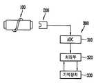
도 1은 거리센서를 이용한 회전량 감지장치의 의 블록도.1 is a block diagram of a rotation amount sensing device using a distance sensor.
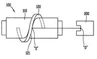
도 2는 나선 로터와 거리센서의 작용 설명도.2 is an explanatory view of the action of the spiral rotor and the distance sensor.
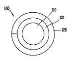
도 3은 나선 로터의 측면도.3 is a side view of the spiral rotor;
<도면의 주요부분에 대한 부호의 설명><Description of the symbols for the main parts of the drawings>
100 : 나선 로터100: spiral rotor
110 : 회전축110: rotation axis
120 : 나선형 감지부120: spiral detection unit
121 : 감지면121: sensing surface
200 : 거리센서200: distance sensor
300 : 센서 회로부300: sensor circuit
본 발명은 거리센서를 이용한 회전량 감지장치거리센서를 이용한 회전량 감지장치에 관한 것으로, 특히 나선형 감지부를 가지는 나선 로터의 일측에 하나의 거리센서를 설치하여 제어 대상부의 회전량을 간편하고 정밀하게 감지함으로써 휴대폰과 같은 소형 이동단말기에 적합하도록 한 거리센서를 이용한 회전량 감지장치거리센서를 이용한 회전량 감지장치에 관한 것이다.The present invention relates to a rotation amount sensing device using a distance sensor, and more particularly, to a rotation amount sensing device using a distance sensor, in particular, by installing one distance sensor on one side of a spiral rotor having a spiral sensing part to easily and precisely control the rotation amount of a control target part. The present invention relates to a rotation amount sensing device using a distance sensor by sensing a distance sensor adapted to a small mobile terminal such as a mobile phone.
최근 휴대폰과 같은 이동단말기의 기능이 점차 다양해짐에 따라, 이동단말기는 음성으로 의사전달을 하는 전화통화의 용도뿐만 아니라 문자로 메시지를 전달하는 단문 문자 서비스(SMS : Short Message Service)나 인터넷 검색 등과 같은 다양한 용도로 이용되고 있으며, 상기의 단문 문자 서비스나 인터넷 검색 등과 같이 디스플레이부를 사용하는 작업의 횟수는 점차 증가하는 추세에 있다.Recently, as the functions of a mobile terminal such as a mobile phone are gradually diversified, the mobile terminal uses a short message service (SMS) or an Internet search that delivers a text message as well as the use of a telephone call to communicate by voice. As used for various purposes, the number of operations using the display unit, such as the short text service or Internet search, is gradually increasing.
그러나, 이동단말기의 소형화 추세로 인하여 디스플레이부의 대형화에는 한계가 있기 때문에, 상기와 같은 단문 문자 서비스나 인터넷 검색과 같은 작업을 할 때에 수신 또는 발신된 문자 메시지나 검색중인 검색내용을 디스플레이부의 한 화면에 나타낼 수 없게 되므로, 전체 내용을 보기 위해서는 방향키를 여러 번 눌러서 디스플레이부 화면을 이동시켜야 한다는 단점이 있었다.However, since the size of the display unit is limited due to the miniaturization trend of mobile terminals, text messages received or searched for or received during a short text service or an Internet search are displayed on one screen of the display unit. Since it cannot be displayed, there was a disadvantage in that the display unit screen must be moved by pressing the arrow keys several times in order to view the entire contents.
특히, 메뉴의 선택단계가 많은 인터넷 검색을 하는 경우에는 자신이 원하는 내용을 찾기 위해서 많은 키 조작이 필요하게 되어 사용하기가 매우 불편하였다.In particular, in the case of internet search with a large number of selection stages of menus, it is very inconvenient to use because a large number of key operations are required to find a desired content.
따라서, 이동단말기에 휠 스위치(휠 버튼)을 설치하여 디스플레이부를 스크롤(scroll)시키면서 볼 수 있도록 한 장치들이 제안되고 있으나, 휠 스위치의 회전을 감지하기 위한 적합한 회전량 감지장치가 개발되지 않음으로써 이동단말기와 같 은 소형 제품에 휠 스위치를 실제로 적용하는 단계에 이르지는 못하고 있다.Therefore, devices have been proposed to install a wheel switch (wheel button) on the mobile terminal so that the display unit can be scrolled while being scrolled. However, a suitable rotation amount sensing device for detecting rotation of the wheel switch has not been developed. The practical application of wheel switches to small products such as handsets has not been reached.
일반적으로 회전량을 감지하기 위한 로터리 엔코더는 기계요소의 회전량을 디지털 신호로 바꾸기 위하여 사용되는 것으로서, 로버트아암의 각도조절, 콘베이어장치의 속도제어, 수치제어 선반 절단기 자동차엔진의 제어장치를 컴퓨터로 제어하기위한 기계장치에 널리 채용하고 있으며, 이러한 종래의 엔코더는 원판에 다수의 슬롯을 형성한 디스크를 축에 장착하고 디스크의 일측에 장착된 발광소자로 부터의 빛을 디스크 구멍을 통과시켜 디스크의 반대편에 장착된 수광소자로 감지한 다음 회로기판에서 그 빛의 속도와 위치를 검출했는데 이때 발광소자와 수광소자에 감지되는 빛의 강약은 전자신호로 변환되고 회전당 100-1024 펄스의 주기적 신호가 발생된다.In general, a rotary encoder for detecting the rotation amount is used to convert the rotation amount of a mechanical element into a digital signal. The angle control of the robot arm, the speed control of the conveyor device, the numerical control lathe cutter control device of the automobile engine is carried out by the computer. It is widely used in machinery for controlling, and this conventional encoder mounts a disk having a plurality of slots in a disk on a shaft and passes light from a light emitting element mounted on one side of the disk through a disk hole. It is detected by the light receiving element mounted on the opposite side, and then the speed and position of the light is detected on the circuit board. The light intensity detected by the light emitting element and the light receiving element is converted into an electronic signal and a periodic signal of 100-1024 pulses per revolution is generated. Is generated.
그러나 이와 같은 종래의 엔코더에서는 빛을 주고 받는 두개의 소자와 그 사이에 위치한 디스크가 정확한 일직선이 되도록 정렬시켜야 하는 기계적 조립이 어려웠고, 디스크의 설계의 가공도 까다로우며, 이들 세가지 광학적 부품을 배열, 정립하는 구조는 복잡할 수 밖에 없을 뿐만 아니라 일단 정확한 조립을 하더라도 이들 부품은 충격에 대한 안정성이 없어서 약한 충격에도 축위치 편차 등의 정밀성이 훼손되어 펄스가 잘 못 발생되고, 분해능이 떨어지는 문제점이 있었으며, 다수개의 슬릿이 형성된 원판으로 빛을 통과시키고 차단시키는 횟수로 회전량을 감지하는 것이므로 연속적인 회전량을 감지하기 어렵게 되는 문제점이 있었다.However, in such a conventional encoder, it is difficult to assemble mechanically, in which two elements to transmit and receive light and a disk located between them are precisely aligned, and the design of the disk is difficult, and the three optical components are arranged, The upright structure is inevitably complicated, and even if it is correctly assembled, these parts have no stability against impact, so the precision of axial position deviation is compromised even with a weak impact, resulting in poor pulse and poor resolution. In order to detect the amount of rotation by the number of times that the light passes through and blocks the disc formed with a plurality of slits, it is difficult to detect the continuous amount of rotation.
따라서, 위와 같은 종래의 로터리 엔코더는 휴대폰과 같은 소형 이동단말기에 적용하기가 현실적으로 어렵게 되는 것이었다.Therefore, the conventional rotary encoder as described above was difficult to apply to a small mobile terminal such as a mobile phone in reality.
본 발명은 상기한 바와 같은 종래의 문제점 및 결함을 해소하기 위하여 창안한 것으로, 나선형 감지부를 가지는 나선 로터의 일측에 하나의 거리센서를 설치하여 제어 대상부의 회전량을 간편하고 정밀하게 감지함으로써 휴대폰과 같은 소형 이동단말기에 유리하게 적용할 수 있게 되는 거리센서를 이용한 회전량 감지장치거리센서를 이용한 회전량 감지장치를 제공하고자 함에 목적이 있다.The present invention has been made in order to solve the above-mentioned problems and defects as described above, by installing one distance sensor on one side of the spiral rotor having a spiral sensing unit to easily and precisely detect the amount of rotation of the control unit and the mobile phone. It is an object of the present invention to provide a rotation amount sensing device using a distance sensor that can be advantageously applied to the same small mobile terminal.
위와 같은 목적을 달성하기 위하여 본 발명에 의한 거리센서를 이용한 회전량 감지장치거리센서를 이용한 회전량 감지장치는 회전축의 주위에 나선형 감지부가 형성되는 나선 로터와, 상기 나선 로터의 회전에 의해 변화되는 나선형 감지부의 감지면과의 거리를 감지하는 거리센서와, 상기 거리센서의 감지신호를 입력받아 디스플레이 스크롤 등 각종 기능을 제어하기 위한 전기적 신호로 처리하기 위한 센서 회로부를 포함하여 구성된다.Rotation amount sensing device using a distance sensor according to the present invention in order to achieve the above object, the rotation amount detecting device using a distance sensor is a spiral rotor formed around the rotation axis and the spiral rotor is changed by the rotation of the spiral rotor It comprises a distance sensor for sensing the distance to the sensing surface of the spiral detection unit, and a sensor circuit unit for receiving the detection signal of the distance sensor as an electrical signal for controlling various functions such as display scroll.
이와 같은 본 발명의 장치는 예를 들어 휴대용 이동단말기의 휠 스위치에 적용하여 휠이 돌아가는 각도에 따라 나선 로터의 나선형 감지면과 거리센서의 거리가 일정하게 연속적으로 변하므로 이 변화되는 거리를 측정하여 디스플레이부의 스크롤 바(scroll bar) 등으로 사용하게 된다.Such a device of the present invention is applied to the wheel switch of a portable mobile terminal, for example, the distance between the spiral sensing surface of the spiral rotor and the distance sensor changes constantly according to the angle of rotation of the wheel, and thus the measured distance is changed. It is used as a scroll bar of the display unit.
이하, 본 발명을 첨부한 도면에 실시예를 들어 상세히 설명하면 다음과 같다.Hereinafter, with reference to the accompanying drawings, the present invention will be described in detail as follows.
도 1 내지 도 3은 본 발명에 의한 거리센서를 이용한 회전량 감지장치에 관 한 도면으로서, 도 1에는 거리센서를 이용한 회전량 감지장치의 의 블록도가 도시되고, 도 2에는 나선 로터와 거리센서의 작용 설명도가 도시되어 있으며, 도 3에는 나선 로터의 측면도가 도시되어 있다.1 to 3 are views of the rotation amount sensing device using a distance sensor according to the present invention, Figure 1 is a block diagram of the rotation amount sensing device using a distance sensor, Figure 2 is a spiral rotor and the distance An explanatory view of the action of the sensor is shown and a side view of the spiral rotor is shown in FIG. 3.
이에 도시한 바와 같이 회전축(110)의 주위에 나선형 감지부(120)가 형성되는 나선 로터(100)와, 상기 나선 로터(100)의 회전에 의해 변화되는 나선형 감지부(120)의 감지면(121)과의 거리를 감지하는 거리센서(200)와, 상기 거리센서(200)의 감지신호를 입력받아 디스플레이 스크롤 등 각종 기능을 제어하기 위한 전기적 신호로 처리하기 위한 센서 회로부(300)를 포함하여 구성된다.As shown therein, the
상기 나선 로터(100)는 예를 들어 휠 스위치와 같은 감지 대상체의 회전부에 연결되어 사용되며, 휠이 일정한 속도로 돌아감에 따라 거리센서(200)로부터 나선 로터(100)의 감지면(121)까지의 거리, 즉 거리센서(200)의 기준위치(O)로부터 감지면(121)의 감지위치(S)까지의 거리가 연속적으로 변하므로 거리센서(200)로 이 변화되는 거리를 측정하게 된다.The
상기 나선 로터(100)는 회전축(110)의 주면에 나선형 감지부(120)가 1피치(pitch) 만큼 형성되는 것이 바람직하나, 필요에 따라 1피치 이하로 형성될 수 있으며, 예를 들어 휠 스위치 등의 회전부에 연결되어 회전하게 된다.The
상기 센서 회로부(300)는 통상의 거리센서 응용 회로부를 이용하며, 예를 들어 거리센서(200)로부터 나오는 아날로그 값을 디지털로 바꿔주는 ADC(아나로그 디지털 변환부)(310), 상기 ADC(310)에 연결되어 나선 로터(100)가 회전하기 전의 거리 값과, 회전한 다음의 거리 값을 비교하고 대상체의 동작을 제어하기 위한 신호 를 처리하는 신호처리부(320)와, 상기 신호처리부(300)와 연결되어 나선 로터(100)의 회전에 따른 거리 값과 이외에 대상체의 동작 제어를 위한 데이터를 기억하는 기억장치(330)를 포함하여 구성된다.The
이와 같은 본 발명에 의한 거리센서를 이용한 회전량 감지장치는 나선 로터(100)의 일측에 일정한 거리를 두고 설치된 거리센서(200)가 나선 로터(100)의 회전에 변하는 나선형 감지부(120)의 감지면(121)과의 거리를 감지함으로써 휠 스위치의 회전량을 인식하여 스크롤 바 등으로 사용하며, 나선 로터(100)가 회전하기 전 값과 회전 한 후의 값을 비교하여 서로 다를 경우 휠의 회전을 인식하고, 거리 값의 차에 의해 회전량을 인식하며, 거리 값의 차가 음수인지, 양수인지를 판별하여 휠이 회전하는 방향을 인식하여 스크롤 바의 동작을 제어한다.The rotation amount sensing device using the distance sensor according to the present invention is the
그리고, 나선 로터(100)가 회전함에 따라 거리센서(200)의 기준위치(O)로부터 감지면(121)의 센싱위치(S)까지의 거리가 연속적으로 변하고, 거리센서(200)는 이 거리의 변화를 연속적으로 감지하게 되어 나선 로터(100)의 회전량을 연속적으로 감지할 수 있게 됨으로써 휠 스위치 등의 회전부를 연속적인 데이터로 정밀 제어할 수 있게 된다.Then, as the
이상에서 설명한 바와 같은 거리센서를 이용한 회전량 감지장치는 나선형 감지부를 가지는 나선 로터의 일측에 하나의 거리센서를 설치하여 제어 대상부의 회전량을 감지하도록 되어 있으므로 부품수가 감소되고, 설계 조립이 간편하며, 분해능이 향상되는 이점이 있다.Rotation amount sensing device using the distance sensor as described above is installed to one distance sensor on one side of the spiral rotor having a spiral sensing unit to detect the amount of rotation of the control target part, the number of parts is reduced, design assembly is easy This has the advantage that the resolution is improved.
뿐만 아니라, 나선 로터가 회전함에 따라 거리센서의 기준위치로부터 감지면의 센싱위치까지의 거리가 연속적으로 변하고, 거리센서는 이 거리의 변화를 연속적으로 감지하게 되어 나선 로터의 회전량을 연속적으로 감지할 수 있게 됨으로써 휠 스위치 등의 회전부를 연속적인 데이터로 정밀 제어할 수 있는 이점이 있다.In addition, as the spiral rotor rotates, the distance from the reference position of the distance sensor to the sensing position on the sensing surface changes continuously, and the distance sensor continuously detects the change in this distance, thereby continuously detecting the amount of rotation of the spiral rotor. Being able to do so has the advantage of precisely controlling the rotating part such as a wheel switch with continuous data.
따라서, 본 발명에 의한 거리센서를 이용한 회전량 감지장치는 휴대폰과 같은 이동단말기에도 매우 유리하게 적용할 수 있는 효과가 있다.Therefore, the rotation amount sensing device using the distance sensor according to the present invention has an effect that can be very advantageously applied to a mobile terminal such as a mobile phone.
Claims (5)
Translated fromKoreanPriority Applications (1)
| Application Number | Priority Date | Filing Date | Title |
|---|---|---|---|
| KR1020040040123AKR100575785B1 (en) | 2004-06-02 | 2004-06-02 | Rotation amount detection device using distance sensor |
Applications Claiming Priority (1)
| Application Number | Priority Date | Filing Date | Title |
|---|---|---|---|
| KR1020040040123AKR100575785B1 (en) | 2004-06-02 | 2004-06-02 | Rotation amount detection device using distance sensor |
Publications (2)
| Publication Number | Publication Date |
|---|---|
| KR20050114986A KR20050114986A (en) | 2005-12-07 |
| KR100575785B1true KR100575785B1 (en) | 2006-05-03 |
Family
ID=37289081
Family Applications (1)
| Application Number | Title | Priority Date | Filing Date |
|---|---|---|---|
| KR1020040040123AExpired - Fee RelatedKR100575785B1 (en) | 2004-06-02 | 2004-06-02 | Rotation amount detection device using distance sensor |
Country Status (1)
| Country | Link |
|---|---|
| KR (1) | KR100575785B1 (en) |
Cited By (1)
| Publication number | Priority date | Publication date | Assignee | Title |
|---|---|---|---|---|
| DE102024104021A1 (en) | 2024-02-14 | 2025-08-14 | Valeo Schalter Und Sensoren Gmbh | Input device, control system and steering wheel for a motor vehicle and method for detecting a user input and for controlling a vehicle function |
Families Citing this family (1)
| Publication number | Priority date | Publication date | Assignee | Title |
|---|---|---|---|---|
| CN119772419B (en)* | 2025-03-12 | 2025-07-29 | 江苏佳力得新材料科技有限公司 | Pipe fitting cutting equipment for space truss |
Citations (1)
| Publication number | Priority date | Publication date | Assignee | Title |
|---|---|---|---|---|
| KR20000047803A (en)* | 1998-12-04 | 2000-07-25 | 이데이 노부유끼 | Switch mechanism |
- 2004
- 2004-06-02KRKR1020040040123Apatent/KR100575785B1/ennot_activeExpired - Fee Related
Patent Citations (1)
| Publication number | Priority date | Publication date | Assignee | Title |
|---|---|---|---|---|
| KR20000047803A (en)* | 1998-12-04 | 2000-07-25 | 이데이 노부유끼 | Switch mechanism |
Cited By (1)
| Publication number | Priority date | Publication date | Assignee | Title |
|---|---|---|---|---|
| DE102024104021A1 (en) | 2024-02-14 | 2025-08-14 | Valeo Schalter Und Sensoren Gmbh | Input device, control system and steering wheel for a motor vehicle and method for detecting a user input and for controlling a vehicle function |
Also Published As
| Publication number | Publication date |
|---|---|
| KR20050114986A (en) | 2005-12-07 |
Similar Documents
| Publication | Publication Date | Title |
|---|---|---|
| US7183536B2 (en) | Motion encoder | |
| WO1999026117A1 (en) | Information processor | |
| KR100999716B1 (en) | System and method for navigating a menu of a mobile communication device | |
| KR100739210B1 (en) | Rotary input device | |
| GB2357634A (en) | Rotary switch with encoder pattern for sensing rotation | |
| HUP0202599A2 (en) | Input element for a telephone | |
| CA2528617A1 (en) | A rotator with rim select functionality | |
| JP2007123101A (en) | Input device and electronic apparatus | |
| CN103178866B (en) | A kind of terminal equipment and using method thereof | |
| CN113010052A (en) | Smart watch, interaction method and interaction device | |
| US7705838B2 (en) | Movable user interface | |
| KR100575785B1 (en) | Rotation amount detection device using distance sensor | |
| US20040036677A1 (en) | Optical trackball device and electronic apparatus | |
| US20080290261A1 (en) | Optical Encoder | |
| KR101589743B1 (en) | Apparatus for wheel running and portable electronic device having the same | |
| JP3889416B2 (en) | Ergonomic pointing device | |
| JP4134524B2 (en) | Input device | |
| RU2444147C2 (en) | Mobile communication terminal, having input device | |
| EP2026169A1 (en) | Detection means | |
| CN110162196B (en) | Mouse and control method thereof | |
| JPH08317034A (en) | Input processing method and terminal equipment | |
| CN100472386C (en) | Information processing device and method | |
| JP2009092543A (en) | Measuring apparatus | |
| KR101285860B1 (en) | Rotating input device of mobile terminal and mobile terminal having the same | |
| KR101027124B1 (en) | Portable terminal with rotary button and control signal generation method using same |
Legal Events
| Date | Code | Title | Description |
|---|---|---|---|
| A201 | Request for examination | ||
| PA0109 | Patent application | St.27 status event code:A-0-1-A10-A12-nap-PA0109 | |
| PA0201 | Request for examination | St.27 status event code:A-1-2-D10-D11-exm-PA0201 | |
| PG1501 | Laying open of application | St.27 status event code:A-1-1-Q10-Q12-nap-PG1501 | |
| D13-X000 | Search requested | St.27 status event code:A-1-2-D10-D13-srh-X000 | |
| D14-X000 | Search report completed | St.27 status event code:A-1-2-D10-D14-srh-X000 | |
| E701 | Decision to grant or registration of patent right | ||
| PE0701 | Decision of registration | St.27 status event code:A-1-2-D10-D22-exm-PE0701 | |
| GRNT | Written decision to grant | ||
| PR0701 | Registration of establishment | St.27 status event code:A-2-4-F10-F11-exm-PR0701 | |
| PR1002 | Payment of registration fee | St.27 status event code:A-2-2-U10-U11-oth-PR1002 Fee payment year number:1 | |
| PG1601 | Publication of registration | St.27 status event code:A-4-4-Q10-Q13-nap-PG1601 | |
| PN2301 | Change of applicant | St.27 status event code:A-5-5-R10-R13-asn-PN2301 St.27 status event code:A-5-5-R10-R11-asn-PN2301 | |
| L13-X000 | Limitation or reissue of ip right requested | St.27 status event code:A-2-3-L10-L13-lim-X000 | |
| U15-X000 | Partial renewal or maintenance fee paid modifying the ip right scope | St.27 status event code:A-4-4-U10-U15-oth-X000 | |
| PR1001 | Payment of annual fee | St.27 status event code:A-4-4-U10-U11-oth-PR1001 Fee payment year number:4 | |
| R18-X000 | Changes to party contact information recorded | St.27 status event code:A-5-5-R10-R18-oth-X000 | |
| R18-X000 | Changes to party contact information recorded | St.27 status event code:A-5-5-R10-R18-oth-X000 | |
| PR1001 | Payment of annual fee | St.27 status event code:A-4-4-U10-U11-oth-PR1001 Fee payment year number:5 | |
| PR1001 | Payment of annual fee | St.27 status event code:A-4-4-U10-U11-oth-PR1001 Fee payment year number:6 | |
| PR1001 | Payment of annual fee | St.27 status event code:A-4-4-U10-U11-oth-PR1001 Fee payment year number:7 | |
| FPAY | Annual fee payment | Payment date:20130326 Year of fee payment:8 | |
| PR1001 | Payment of annual fee | St.27 status event code:A-4-4-U10-U11-oth-PR1001 Fee payment year number:8 | |
| FPAY | Annual fee payment | Payment date:20140414 Year of fee payment:9 | |
| PR1001 | Payment of annual fee | St.27 status event code:A-4-4-U10-U11-oth-PR1001 Fee payment year number:9 | |
| PR1001 | Payment of annual fee | St.27 status event code:A-4-4-U10-U11-oth-PR1001 Fee payment year number:10 | |
| PN2301 | Change of applicant | St.27 status event code:A-5-5-R10-R13-asn-PN2301 St.27 status event code:A-5-5-R10-R11-asn-PN2301 | |
| FPAY | Annual fee payment | Payment date:20160324 Year of fee payment:11 | |
| PR1001 | Payment of annual fee | St.27 status event code:A-4-4-U10-U11-oth-PR1001 Fee payment year number:11 | |
| LAPS | Lapse due to unpaid annual fee | ||
| PC1903 | Unpaid annual fee | St.27 status event code:A-4-4-U10-U13-oth-PC1903 Not in force date:20170426 Payment event data comment text:Termination Category : DEFAULT_OF_REGISTRATION_FEE | |
| P22-X000 | Classification modified | St.27 status event code:A-4-4-P10-P22-nap-X000 | |
| PC1903 | Unpaid annual fee | St.27 status event code:N-4-6-H10-H13-oth-PC1903 Ip right cessation event data comment text:Termination Category : DEFAULT_OF_REGISTRATION_FEE Not in force date:20170426 | |
| PN2301 | Change of applicant | St.27 status event code:A-5-5-R10-R13-asn-PN2301 St.27 status event code:A-5-5-R10-R11-asn-PN2301 |