KR100574943B1 - Image conversion method and device - Google Patents
Image conversion method and deviceDownload PDFInfo
- Publication number
- KR100574943B1 KR100574943B1KR1020030037137AKR20030037137AKR100574943B1KR 100574943 B1KR100574943 B1KR 100574943B1KR 1020030037137 AKR1020030037137 AKR 1020030037137AKR 20030037137 AKR20030037137 AKR 20030037137AKR 100574943 B1KR100574943 B1KR 100574943B1
- Authority
- KR
- South Korea
- Prior art keywords
- field
- conversion
- image
- interlaced
- motion
- Prior art date
- Legal status (The legal status is an assumption and is not a legal conclusion. Google has not performed a legal analysis and makes no representation as to the accuracy of the status listed.)
- Expired - Fee Related
Links
Images

Classifications
- H—ELECTRICITY
- H04—ELECTRIC COMMUNICATION TECHNIQUE
- H04N—PICTORIAL COMMUNICATION, e.g. TELEVISION
- H04N7/00—Television systems
- H04N7/01—Conversion of standards, e.g. involving analogue television standards or digital television standards processed at pixel level
- H—ELECTRICITY
- H04—ELECTRIC COMMUNICATION TECHNIQUE
- H04N—PICTORIAL COMMUNICATION, e.g. TELEVISION
- H04N7/00—Television systems
- H04N7/01—Conversion of standards, e.g. involving analogue television standards or digital television standards processed at pixel level
- H04N7/0117—Conversion of standards, e.g. involving analogue television standards or digital television standards processed at pixel level involving conversion of the spatial resolution of the incoming video signal
- H04N7/012—Conversion between an interlaced and a progressive signal
- H—ELECTRICITY
- H04—ELECTRIC COMMUNICATION TECHNIQUE
- H04N—PICTORIAL COMMUNICATION, e.g. TELEVISION
- H04N7/00—Television systems
- H04N7/01—Conversion of standards, e.g. involving analogue television standards or digital television standards processed at pixel level
- H04N7/0135—Conversion of standards, e.g. involving analogue television standards or digital television standards processed at pixel level involving interpolation processes
- H04N7/0137—Conversion of standards, e.g. involving analogue television standards or digital television standards processed at pixel level involving interpolation processes dependent on presence/absence of motion, e.g. of motion zones
- H—ELECTRICITY
- H04—ELECTRIC COMMUNICATION TECHNIQUE
- H04N—PICTORIAL COMMUNICATION, e.g. TELEVISION
- H04N7/00—Television systems
- H04N7/01—Conversion of standards, e.g. involving analogue television standards or digital television standards processed at pixel level
- H04N7/0135—Conversion of standards, e.g. involving analogue television standards or digital television standards processed at pixel level involving interpolation processes
- H04N7/0142—Conversion of standards, e.g. involving analogue television standards or digital television standards processed at pixel level involving interpolation processes the interpolation being edge adaptive
Landscapes
- Engineering & Computer Science (AREA)
- Computer Graphics (AREA)
- Multimedia (AREA)
- Signal Processing (AREA)
- Television Systems (AREA)
- Controls And Circuits For Display Device (AREA)
Abstract
Translated fromKoreanDescription
Translated fromKorean본 발명의 상세한 설명에서 인용되는 도면을 보다 충분히 이해하기 위하여 각 도면의 상세한 설명이 제공된다.The detailed description of each drawing is provided in order to provide a thorough understanding of the drawings cited in the detailed description of the invention.
도 1은 비월 주사 방법을 사용하는 디스플레이 장치에서 정지 영상을 디스플레이하는 경우 화면 떨림이 발생되는 원인을 개념적으로 보여주기 위한 도면이다.FIG. 1 is a diagram conceptually illustrating a cause of screen shaking when displaying a still image in a display apparatus using an interlaced scanning method.
도 2는 본 발명의 실시예에 따른 영상 변환 장치의 블락도를 나타낸다.2 is a block diagram of an image conversion apparatus according to an embodiment of the present invention.
도 3은 본 발명에 따른 영상 변환 장치를 사용하는 경우, 비월 주사 방식을 사용하는 디스플레이 장치에서 화면 떨림이 없는 정지 화면을 만드는 방법을 보여주는 도면이다.FIG. 3 is a view illustrating a method of making a still image free of image shaking in a display apparatus using an interlaced scanning method when using the image conversion apparatus according to the present invention.
본 발명은 영상 변환 방법 및 영상 변환 장치에 관한 것으로, 보다 상세하게는 비월 주사 방법을 사용하는 디스플레이 장치에서 정지 영상을 디스플레이하는 경우에 발생되는 화면 떨림(flicker)을 방지하기 위한 장치 및 방법에 관한 것이다.The present invention relates to an image conversion method and an image conversion device, and more particularly, to an apparatus and method for preventing flicker caused when displaying a still image in a display device using an interlaced scanning method. will be.
미국 NTSC 방송 표준을 기준으로 할 때, 비월 주사 방법(interlaced scanning)을 사용하는 텔레비전 수상기는 1/60초마다 탑 필드(top field)와 바텀 필드(bottom field)를 번갈아 디스플레이한다. 따라서 탑 필드는 초당 30번 디스플레이되고, 바텀 필드는 초당 30번 디스플레이된다.Based on the US NTSC broadcast standard, television receivers using interlaced scanning alternately display the top field and bottom field every 1/60 second. Therefore, the top field is displayed 30 times per second and the bottom field is displayed 30 times per second.
상기 탑 필드는 제1필드 또는 홀수 필드라고도 불리며, 모든 홀수번 주사선들(1, 3, 5, 등)로 이루어진다. 상기 바텀 필드는 제2필드 또는 짝수 필드라고도 불리며 모든 짝수번 주사선들(2, 4, 6, 등)로 이루어진다.The top field is also called a first field or an odd field, and consists of all odd numbered
그러나 ATSC 규격에 의하여 순차주사 방법(progressive scanning)을 사용하는 디지털 TV의 수상기 및 컴퓨터의 모니터는 1/60초마다 하나의 프레임을 디스플레이한다.However, according to the ATSC standard, a receiver of a digital TV and a monitor of a computer using progressive scanning display one frame every 1/60 second.
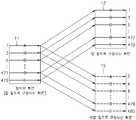
도 1은 비월 주사 방법을 사용하는 디스플레이 장치에서 정지 영상을 디스플레이하는 경우 화면 떨림이 발생되는 원인을 개념적으로 보여주기 위한 도면이다.FIG. 1 is a diagram conceptually illustrating a cause of screen shaking when displaying a still image in a display apparatus using an interlaced scanning method.
도 1은 BOB라고 알려져 있는 필드 내 보간(intra-field interpolation)방법을 이용하여 비월주사를 위한 영상신호를 순차주사를 위한 영상신호로 변환하는 방법을 설명하기 위한 것으로, 화면(11)은 현재 정지(pause)시켜야 하는 화면을 나타낸다.FIG. 1 illustrates a method of converting an image signal for interlaced scanning into an image signal for sequential scanning using an intra-field interpolation method known as BOB. The
예컨대 정지된 화면(11)이 탑 필드로 구성되는 화면이라고 가정하면, 비월 주사 방법을 사용하는 디스플레이 장치는 그 구조상 탑 필드로 구성되는 화면(13)과 바텀 필드로 구성되는 화면(15)을 번갈아 디스플레이한다.For example, assuming that the
즉, 정지된 화면(11)에서 각 홀수번 주사선(1, 3, 5, ..., 477, 479)을 통하여 디스플레이되는 각 영상(A, B, C,..., D, E)은 탑 필드로 구성되는 화면(13) 에서는 각 홀수번 주사선(1, 3, 5, ..., 477, 479)을 통하여 디스플레이되고, 바텀 필드를 구성하는 화면(15)에서는 각 짝수번 주사선(2, 4, 6, ..., 478, 480)을 통하여 디스플레이된다.That is, each of the images A, B, C, ..., D, E displayed through the
따라서 비월 주사 방법을 사용하는 디스플레이 장치에서 화면 떨림 현상은 동일한 영상(A, B, C, ..., D, E)을 디스플레이하는 홀수번 주사선들과 짝수번 주사선들의 위치차이에 의하여 발생된다. 즉, A라는 영상이 1번 주사선과 2번 주사선을 통하여 번갈아 디스플레이 되므로 화면 떨림 현상이 발생된다.Therefore, in the display apparatus using the interlaced scanning method, the screen shake is caused by the positional difference between odd-numbered scan lines and even-numbered scan lines displaying the same image (A, B, C, ..., D, E). That is, the image A is displayed alternately through the
또한, WEAVE라고 알려져 있는 필드 간 보간(inter-field interpolation)방법은 탑 필드와 바텀 필드를 결합하여 하나의 프레임을 만드는 방법으로, 화면을 정지시키는 경우 화면 중에서 정지된 영상은 잘 디스플레이되나 움직이는 영상은 눈에 거슬리는 수평선이 생기는 문제점이 있다.In addition, inter-field interpolation method, known as WEAVE, is a method that combines the top field and the bottom field to make a frame. When the screen is stopped, the still image is displayed well but the moving image is displayed. There is a problem that an unobtrusive horizon occurs.
따라서 본 발명이 이루고자 하는 기술적인 과제는 비월 주사 방식을 사용하는 디스플레이 장치에서 정지 영상을 디스플레이하는 경우 떨림 없는 고화질의 정지화면을 만들기 위한 영상변환 방법 및 영상 변환 장치를 제공하는 것이다.Accordingly, the present invention has been made in an effort to provide an image conversion method and an image conversion apparatus for creating a still image having high image quality without shaking when displaying a still image in a display apparatus using an interlaced scanning method.
상기 기술적 과제를 달성하기 위한 영상 변환 방법은 정지 명령에 응답하여 적어도 하나의 필드로부터 정지된 프레임을 생성하는 단계; 및 정지 동작동안, 상기 정지된 프레임으로부터 탑 필드와 바텀 필드를 번갈아 출력하는 단계를 구비한다.According to an aspect of the present invention, there is provided a method of converting an image, the method comprising: generating a still frame from at least one field in response to a stop command; And outputting the top field and the bottom field alternately from the stopped frame during the stop operation.
상기 기술적 과제를 달성하기 위한 영상 변환 방법은 정지 명령에 응답하여 적어도 하나의 필드로부터 정지된 프레임을 생성하는 단계; 및 상기 프레임을 구성하는 탑 필드와 바텀 필드 중에서 어느 하나의 필드를 선택하고, 선택된 필드를 선입-선출 방법으로 프로세싱하는 단계를 구비한다.According to an aspect of the present invention, there is provided a method of converting an image, the method comprising: generating a still frame from at least one field in response to a stop command; And selecting any one of a top field and a bottom field constituting the frame, and processing the selected field by a first-in-first-out method.
상기 정지된 프레임은 위브(WEAVE), 밥(BOB), 움직임 적응 비월-순차 변환(MA-IPC) 또는 움직임 보상 비월-순차 변환(MC-IPC)에 의하여 생성된다.The frozen frame is generated by a WEAVE, Bob, motion adaptive interlaced-sequential transformation (MA-IPC) or motion compensated interlaced-sequential transformation (MC-IPC).
상기 프로세싱하는 단계는 상기 선택된 필드를 선입-선출 방법으로 버퍼링하는 단계; 및 버퍼링된 필드를 출력하는 단계를 구비한다.The processing may include buffering the selected field in a first-in, first-out method; And outputting the buffered field.
상기 기술적 과제를 달성하기 위한 영상 변환 장치는 정지 명령에 응답하여 입력되는 적어도 하나의 필드로부터 정지된 프레임을 생성하는 제1변환회로; 및 상기 제1변환회로에 접속되고, 정지 동작 동안 상기 프레임을 구성하는 탑 필드 데이터와 바텀 필드 데이터를 번갈아 출력하는 제2변환회로를 구비한다.In accordance with one aspect of the present invention, there is provided an image conversion apparatus including: a first conversion circuit configured to generate a still frame from at least one field input in response to a stop command; And a second conversion circuit connected to the first conversion circuit and alternately outputting top field data and bottom field data constituting the frame during a stop operation.
상기 영상 변환 장치는 명령신호에 응답하여 상기 정지 명령을 발생하는 프로세서를 더 구비한다.The image conversion apparatus further includes a processor configured to generate the stop command in response to a command signal.
상기 기술적 과제를 달성하기 위한 영상 변환 장치는 정지 명령에 응답하여 적어도 하나의 필드로부터 정지된 프레임을 생성하는 제1변환 회로; 및 상기 제1변환회로에 접속되고, 상기 프레임을 구성하는 탑 필드와 바텀 필드 중에서 어느 하나의 필드를 선택하고, 선택된 필드를 선입-선출 방법으로 프로세싱하는 제2변환회로를 구비한다.In accordance with one aspect of the present invention, there is provided an image conversion apparatus including: a first conversion circuit configured to generate a still frame from at least one field in response to a stop command; And a second conversion circuit connected to the first conversion circuit, for selecting one of the top field and the bottom field constituting the frame, and processing the selected field by a first-in-first-out method.
본 발명과 본 발명의 동작상의 이점 및 본 발명의 실시에 의하여 달성되는 목적을 충분히 이해하기 위해서는 본 발명의 바람직한 실시예를 예시하는 첨부 도면 및 첨부 도면에 기재된 내용을 참조하여야만 한다.In order to fully understand the present invention, the operational advantages of the present invention, and the objects achieved by the practice of the present invention, reference should be made to the accompanying drawings which illustrate preferred embodiments of the present invention and the contents described in the accompanying drawings.
이하, 첨부한 도면을 참조하여 본 발명의 바람직한 실시예를 설명함으로써, 본 발명을 상세히 설명한다. 각 도면에 제시된 동일한 참조부호는 동일한 부재를 나타낸다.Hereinafter, exemplary embodiments of the present invention will be described in detail with reference to the accompanying drawings. Like reference numerals in the drawings denote like elements.
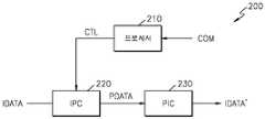
도 2는 본 발명의 실시예에 따른 영상 변환 장치의 블락도를 나타낸다. 도 2를 참조하면, 비월 주사 방법을 사용하는 디스플레이 장치(미도시)에 사용되는 영상 변환 장치(200)는 프로세서(210), 제1변환회로(220) 및 제2변환회로(230)를 구비한다.2 is a block diagram of an image conversion apparatus according to an embodiment of the present invention. 2, an
프로세서(210)는 영상 변환 장치(200)의 외부로부터 입력되는 명령신호(COM)에 응답하여 정지 명령(CTL)을 제1변환회로(220)로 출력한다.The
제1변환회로(220)는 정지 명령(CTL)에 응답하여 적어도 하나의 필드(IDATA)로부터 정지된 프레임(PDATA)을 생성한다. 즉, 제1변환회로(220)는 입력되는 탑 필드 및/또는 바텀 필드를 이용하여 프레임(PDATA)을 생성한다. 정지동작 동안 상기 프레임(PDATA)은 순차 주사 방법을 사용하는 디스플레이 장치를 통하여 정지된 순차 영상(progressive image)으로 구현된다.The
제1변환회로(220)는 위브(WEAVE), 밥(BOB), 움직임 적응 비월-순차 변환(motion-adaptive Interlaced to progressive conversion; MA-IPC) 또는 움직임 보상 비월-순차 변환(motion-compensation Interlaced to progressive conversion; MC-IPC) 등의 영상 포맷 변환 방법을 이용하여 필드(IDATA)를 프레임(PDATA)으로 변환한다.The
현재 정지시켜야 하는 화면이 탑 필드(t)로 구성되는 영상인 경우, BOB은 상기 탑 필드(t)만을 이용하여 프레임(PDATA)을 생성한다.If the current screen to be stopped is an image composed of the top field t, the BOB generates the frame PDATA using only the top field t.
그리고 현재 정지시켜야 하는 화면이 탑 필드(t)로 구성되는 영상인 경우 WEAVE는 상기 탑 필드(t)와 바텀 필드(t+1)로 보간된(interpolated) 프레임(PDATA)을 생성하고, 현재 정지시켜야 하는 화면이 바텀 필드(t)로 구성되는 영상인 경우 WEAVE는 이전의 탑 필드(t-1)와 상기 바텀 필드(t)로 보간된 프레임(PDATA)을 생성한다.If the current screen to be stopped is an image composed of a top field t, WEAVE generates an interpolated frame PDATA between the top field t and the bottom field t + 1, and currently stops the image. If the screen to be a video is composed of a bottom field t, WEAVE generates a frame PDATA interpolated between the previous top field t-1 and the bottom field t.
움직임 적응 비월-순차 변환(MA-IPC)방법은 BOB 또는 WEAVE를 이용하는 방법에 비하여 높은 해상도(resolution)를 갖는 정지된 순차 영상을 만들 수 있다.The motion-adaptive interlaced-sequential conversion (MA-IPC) method can produce a still image having a higher resolution than the method using the BOB or WEAVE.
예컨대 현재 정지시켜야 하는 화면이 탑 필드(t)로 구성되는 영상인 경우, 움직임 적응 비월-순차 변환(MA-IPC)은 이전의 바텀 필드(t-1), 상기 탑 필드(t) 및 다음의 바텀 필드(t+1)를 이용하여 프레임(PDATA)을 생성한다.For example, when the picture to be stopped at present is an image composed of the top field t, the motion adaptive interlaced-sequential conversion (MA-IPC) is performed by the previous bottom field t-1, the top field t, and the next. The frame PDATA is generated using the bottom field t + 1.
즉, 동작이 있는 부분의 영상은 BOB을 이용하여 보간(interpolation)하고, 동작이 없는 부분의 영상은 WEAVE를 이용하여 보간(interpolation)한다.That is, the image of the part having motion is interpolated using BOB, and the image of the part having no motion is interpolated using WEAVE.
예컨대 탑 필드(t)를 페취(fetch)하는 경우, 공간성분은 상기 탑 필드(t)의 (i+1)번째 주사선의 데이터와 상기 탑 필드(t)의 (i-1)번째 주사선의 데이터를 보간한 결과이고, 시간성분은 이전의 바텀 필드(t-1)의 i번째 주사선의 데이터와 다음의 바텀 필드(t+1)의 i번째 주사선의 데이터를 보간한 결과이다.For example, when fetching the top field t, the spatial component is the data of the (i + 1) th scan line of the top field t and the (i-1) th scan line of the top field t. Is a result of interpolating the data of the i th scan line of the previous bottom field t-1 and the i th scan line of the next bottom field t + 1.
공간-시간 필터(spatial-temporal filter)는 상기 공간성분과 상기 시간성분 을 수신하고, 필터링한 결과로서 프레임(PDATA)을 생성한다.A spatial-temporal filter receives the spatial component and the temporal component and generates a frame PDATA as a result of the filtering.
움직임 보상 비월-순차 변환(MC-IPC)은 MPEG 스트림(stream)에 들어있는 움직임 벡터(motion vector)를 사용하여 매크로 블록(macro block)단위로 움직임 보상된 영상(motion compensated image)을 이용하여 프레임(PDATA)을 생성한다.Motion-Compensated Inter-Sequence Conversion (MC-IPC) uses a motion vector contained in an MPEG stream to frame using motion compensated images in macroblock units. Create (PDATA).
제1변환회로(220)는 순차 주사 방법을 사용하는 디스플레이 장치의 규격(예컨대 480P)에 따라 프레임(PDATA)을 출력한다.The
제2변환회로(230)는 제1변환회로(220)로부터 출력되는 프레임(PDATA)을 수신하고, 정지된 영상을 디스플레이 장치에 디스플레이하는 동안(정지 동작 동안), 움직임이 없는 정지된 프레임(PDATA)을 구성하는 탑 필드와 바텀 필드를 번갈아 출력한다.The
즉, 제2변환회로(230)는 프레임(PDATA)을 구성하는 탑 필드와 바텀 필드 중에서 어느 하나의 필드를 선택하고, 선택된 필드를 선입-선출 방법으로 프로세싱(예컨대 버퍼링)한다.That is, the
제2변환회로(230)는 프레임(PDATA)을 구성하는 탑 필드와 바텀 필드로부터 디스플레이 장치에서 실시간으로 요구하는 필드, 즉 상기 디스플레이 장치의 화면에 디스플레이될 필드를 선택적으로 출력한다.The
즉, 디스플레이 장치가 탑 필드를 요구하는 경우 제2변환회로(230)는 모든 홀수번 주사선들 각각의 데이터(이를 '탑 필드 데이터'라 한다.)를 선택적으로 출력하고, 디스플레이 장치가 바텀 필드를 요구하는 경우 제2변환회로(230)는 모든 짝수번 주사선들 각각의 데이터(이를 '바텀 필드 데이터'라 한다.)를 선택적으로 출력한다.That is, when the display device requests the top field, the
제2변환회로(230)는 순차 주사 방법을 사용하는 디스플레이 장치(미도시)의 규격에 따라 탑 필드와 바텀 필드(IDATA')를 번갈아 출력한다. 따라서 상기 디스플레이 장치는 제2변환회로(230)로부터 출력되는 탑 필드와 바텀 필드 중에서 디스플레이될 필드 순서에 따라 선택된 필드를 디스플레이한다.The
도 3은 본 발명에 따른 영상 변환 장치를 사용하는 경우, 비월 주사 방식을 사용하는 디스플레이 장치에서 화면 떨림이 없는 정지 화면을 만드는 방법을 보여주는 도면이다.FIG. 3 is a view illustrating a method of making a still image free of image shaking in a display apparatus using an interlaced scanning method when using the image conversion apparatus according to the present invention.
도 2 및 도 3을 참조하면, 제1변환회로(220)가 정지 명령(CTL)에 응답하여 상술한 영상 포맷 변환 방법을 이용하여 필드(IDATA)로부터 움직임(motion)이 없는 정지된 프레임(PDATA)을 생성하면, 제2변환회로(220)는 프레임(PDATA)을 구성하는 탑 필드와 바텀 필드 중에서 디스플레이될 필드를 선택적으로 출력한다.2 and 3, in response to the stop command CTL, the
여기서 화면(310)은 움직임(motion)이 없는 정지된 프레임(PDATA)으로 구성된 정지화면을 나타내고, 화면(330)은 비월 주사 방법을 사용하는 디스플레이 장치를 통하여 디스플레이된 탑 필드로 구성된 정지화면을 나타내고, 화면(350)은 비월 주사 방법을 사용하는 디스플레이 장치를 통하여 디스플레이된 바텀 필드로 구성된 정지화면을 나타낸다.Here, the
상기 비월 주사 방법을 사용하는 디스플레이 장치가 탑 필드를 요구하는 경우 제2변환회로(230)는 프레임(PDATA)을 구성하는 탑 필드와 바텀 필드 중에서 탑 필드(즉, 탑 필드 데이터)만을 선택적으로 출력하고, 상기 디스플레이 장치가 바텀 필드를 요구하는 경우 제2변환회로(230)는 상기 프레임(PDATA)을 구성하는 탑 필드와 바텀 필드 중에서 바텀 필드(즉, 바텀 필드 데이터)만을 선택적으로 출력한다.When the display apparatus using the interlaced scanning method requires the top field, the
즉, 정지동작 동안 프레임(PDATA)으로 구성되는 정지화면(310)중에서 탑 필드 데이터는 탑 필드로 구성되는 정지화면(330)을 통하여 디스플레되고, 바텀 필드 데이터는 바텀 필드로 구성되는 정지화면(450)을 통하여 디스플레이된다.That is, in the
따라서 화면(310)의 탑 필드 데이터는 화면(330)의 탑 필드 데이터로 사상(mapping)되고, 화면(310)의 바텀 필드 데이터는 화면(450)의 바텀 필드 데이터로 사상되므로, 정지 화면에 떨림이 발생하지 않는다.Therefore, the top field data of the
본 발명은 도면에 도시된 일 실시 예를 참고로 설명되었으나 이는 예시적인 것에 불과하며, 본 기술 분야의 통상의 지식을 가진 자라면 이로부터 다양한 변형 및 균등한 타 실시예가 가능하다는 점을 이해할 것이다. 따라서, 본 발명의 진정한 기술적 보호 범위는 첨부된 등록청구범위의 기술적 사상에 의해 정해져야 할 것이다.Although the present invention has been described with reference to one embodiment shown in the drawings, this is merely exemplary, and those skilled in the art will understand that various modifications and equivalent other embodiments are possible therefrom. Therefore, the true technical protection scope of the present invention will be defined by the technical spirit of the appended claims.
상술한 바와 같이 본 발명에 따른 영상 변환 방법 및 영상 변환 장치는 비월 주사 방식을 사용하는 디스플레이 장치에서 정지 영상을 디스플레이하는 경우 떨림 없는 고화질의 정지화면을 만들 수 있는 효과가 있다.As described above, the image conversion method and the image conversion apparatus according to the present invention have an effect of making a high quality still image without shaking when displaying a still image in a display apparatus using an interlaced scanning method.
Claims (8)
Translated fromKoreanPriority Applications (6)
| Application Number | Priority Date | Filing Date | Title |
|---|---|---|---|
| KR1020030037137AKR100574943B1 (en) | 2003-06-10 | 2003-06-10 | Image conversion method and device |
| US10/811,993US7791672B2 (en) | 2003-06-10 | 2004-03-30 | Scanning conversion apparatus and method |
| DE102004029041ADE102004029041B4 (en) | 2003-06-10 | 2004-06-08 | Scan conversion apparatus and method |
| FR0406237AFR2856218B1 (en) | 2003-06-10 | 2004-06-09 | APPARATUS AND METHOD FOR SCAN CONVERSION |
| JP2004171417AJP4847688B2 (en) | 2003-06-10 | 2004-06-09 | Interlace-progressive converter and conversion method thereof |
| CN2004100640790ACN1574954B (en) | 2003-06-10 | 2004-06-10 | Scanning conversion apparatus and method |
Applications Claiming Priority (1)
| Application Number | Priority Date | Filing Date | Title |
|---|---|---|---|
| KR1020030037137AKR100574943B1 (en) | 2003-06-10 | 2003-06-10 | Image conversion method and device |
Publications (2)
| Publication Number | Publication Date |
|---|---|
| KR20040105966A KR20040105966A (en) | 2004-12-17 |
| KR100574943B1true KR100574943B1 (en) | 2006-05-02 |
Family
ID=33509641
Family Applications (1)
| Application Number | Title | Priority Date | Filing Date |
|---|---|---|---|
| KR1020030037137AExpired - Fee RelatedKR100574943B1 (en) | 2003-06-10 | 2003-06-10 | Image conversion method and device |
Country Status (6)
| Country | Link |
|---|---|
| US (1) | US7791672B2 (en) |
| JP (1) | JP4847688B2 (en) |
| KR (1) | KR100574943B1 (en) |
| CN (1) | CN1574954B (en) |
| DE (1) | DE102004029041B4 (en) |
| FR (1) | FR2856218B1 (en) |
Families Citing this family (4)
| Publication number | Priority date | Publication date | Assignee | Title |
|---|---|---|---|---|
| US20080030615A1 (en)* | 2005-06-29 | 2008-02-07 | Maximino Vasquez | Techniques to switch between video display modes |
| JP4254811B2 (en)* | 2006-05-29 | 2009-04-15 | ソニー株式会社 | Image display device, signal processing device, image display method, and computer program |
| GB2444534A (en)* | 2006-12-06 | 2008-06-11 | Sony Uk Ltd | Assessing the reliability of motion information in motion adaptive image processing |
| GB2503833B (en)* | 2008-12-09 | 2014-04-30 | Snell Ltd | Motion image rendering system |
Citations (4)
| Publication number | Priority date | Publication date | Assignee | Title |
|---|---|---|---|---|
| KR19990030024A (en)* | 1997-09-29 | 1999-04-26 | 김영환 | Apparatus and method for adaptive interlaced scan shape information encoding / decoding |
| KR20010011560A (en)* | 1999-07-29 | 2001-02-15 | 구자홍 | Deinterlacing method of interlaced scanning video |
| JP2001189919A (en)* | 1999-12-28 | 2001-07-10 | Sony Corp | Image information converter and image information conversion method |
| JP2003087797A (en)* | 2001-09-06 | 2003-03-20 | Sony Corp | Apparatus and method for picture information conversion, picture information conversion program, and recording medium |
Family Cites Families (31)
| Publication number | Priority date | Publication date | Assignee | Title |
|---|---|---|---|---|
| JP2574370B2 (en) | 1988-03-07 | 1997-01-22 | 基盤情報システム開発株式会社 | Scan converter for image quality improvement |
| US4989090A (en) | 1989-04-05 | 1991-01-29 | Yves C. Faroudja | Television scan line doubler including temporal median filter |
| GB2231460B (en)* | 1989-05-04 | 1993-06-30 | Sony Corp | Spatial interpolation of digital video signals |
| JP3154272B2 (en)* | 1989-09-13 | 2001-04-09 | キヤノン株式会社 | Image conversion apparatus and method |
| JPH04172875A (en)* | 1990-11-07 | 1992-06-19 | Toshiba Corp | Adaptive contour enhancement circuit |
| DE4211955A1 (en)* | 1992-04-09 | 1993-10-14 | Thomson Brandt Gmbh | Method and device for an interlace progressive conversion |
| FR2700090B1 (en)* | 1992-12-30 | 1995-01-27 | Thomson Csf | Method for deinterlacing frames of a sequence of moving images. |
| JP3060799B2 (en)* | 1993-10-20 | 2000-07-10 | 松下電器産業株式会社 | Progressive scanning signal processing system |
| US5661525A (en)* | 1995-03-27 | 1997-08-26 | Lucent Technologies Inc. | Method and apparatus for converting an interlaced video frame sequence into a progressively-scanned sequence |
| KR0176568B1 (en)* | 1996-01-27 | 1999-05-01 | 김광호 | Device and method for conversion interlaced to progressive scanning |
| CN1096185C (en) | 1996-01-27 | 2002-12-11 | 三星电子株式会社 | Interlaced-to-progressive conversion apparatus and method using motion and spatial correlation |
| JP3814326B2 (en) | 1996-02-15 | 2006-08-30 | 松下電器産業株式会社 | Video signal processing circuit |
| US5936676A (en)* | 1997-08-21 | 1999-08-10 | Miranda Technologies Inc. | Apparatus and method for line interpolating an interlaced video signal |
| JP3514063B2 (en)* | 1997-02-20 | 2004-03-31 | 松下電器産業株式会社 | Receiver |
| US6014182A (en)* | 1997-10-10 | 2000-01-11 | Faroudja Laboratories, Inc. | Film source video detection |
| DE69835802T2 (en)* | 1998-03-09 | 2007-04-12 | Sony Deutschland Gmbh | Method and system for interpolating digital signals |
| JPH11266439A (en) | 1998-03-18 | 1999-09-28 | Hitachi Ltd | Image signal double-speed scanning conversion circuit |
| AU3021999A (en) | 1998-04-03 | 1999-10-25 | Miranda Technologies Inc. | Hdtv up converter |
| JP3293561B2 (en) | 1998-07-29 | 2002-06-17 | 日本電気株式会社 | Image display device and image display method |
| US6239842B1 (en)* | 1998-12-18 | 2001-05-29 | Oplus Technologies Ltd. | Method of de-interlacing video signals using a mixed mode spatial and temporal approximation technique |
| WO2000038419A1 (en)* | 1998-12-22 | 2000-06-29 | Matsushita Electric Industrial Co., Ltd. | Video signal reproducing device |
| KR100731523B1 (en)* | 1999-05-25 | 2007-06-25 | 코닌클리케 필립스 일렉트로닉스 엔.브이. | Conversion of Interlaced Video Signals into Progressive Scanned Video Signals |
| US6459455B1 (en)* | 1999-08-31 | 2002-10-01 | Intel Corporation | Motion adaptive deinterlacing |
| JP2001169252A (en) | 1999-12-06 | 2001-06-22 | Victor Co Of Japan Ltd | Progressive scanning converter and progressive scanning method |
| KR100631496B1 (en)* | 2000-01-12 | 2006-10-09 | 엘지전자 주식회사 | Deinterlacing device |
| US6661464B1 (en)* | 2000-11-21 | 2003-12-09 | Dell Products L.P. | Dynamic video de-interlacing |
| JP4553481B2 (en)* | 2000-12-14 | 2010-09-29 | パナソニック株式会社 | Scanning line interpolation device |
| US6690427B2 (en)* | 2001-01-29 | 2004-02-10 | Ati International Srl | Method and system for de-interlacing/re-interlacing video on a display device on a computer system during operation thereof |
| JP2002290926A (en) | 2001-03-27 | 2002-10-04 | Matsushita Electric Ind Co Ltd | Diagonal adaptive scanning line interpolator |
| KR100393066B1 (en)* | 2001-06-11 | 2003-07-31 | 삼성전자주식회사 | Apparatus and method for adaptive motion compensated de-interlacing video data using adaptive compensated olation and method thereof |
| JP2002369156A (en)* | 2001-06-11 | 2002-12-20 | Mitsubishi Electric Corp | Video signal converter |
- 2003
- 2003-06-10KRKR1020030037137Apatent/KR100574943B1/ennot_activeExpired - Fee Related
- 2004
- 2004-03-30USUS10/811,993patent/US7791672B2/ennot_activeExpired - Fee Related
- 2004-06-08DEDE102004029041Apatent/DE102004029041B4/ennot_activeExpired - Fee Related
- 2004-06-09JPJP2004171417Apatent/JP4847688B2/ennot_activeExpired - Fee Related
- 2004-06-09FRFR0406237Apatent/FR2856218B1/ennot_activeExpired - Fee Related
- 2004-06-10CNCN2004100640790Apatent/CN1574954B/ennot_activeExpired - Fee Related
Patent Citations (4)
| Publication number | Priority date | Publication date | Assignee | Title |
|---|---|---|---|---|
| KR19990030024A (en)* | 1997-09-29 | 1999-04-26 | 김영환 | Apparatus and method for adaptive interlaced scan shape information encoding / decoding |
| KR20010011560A (en)* | 1999-07-29 | 2001-02-15 | 구자홍 | Deinterlacing method of interlaced scanning video |
| JP2001189919A (en)* | 1999-12-28 | 2001-07-10 | Sony Corp | Image information converter and image information conversion method |
| JP2003087797A (en)* | 2001-09-06 | 2003-03-20 | Sony Corp | Apparatus and method for picture information conversion, picture information conversion program, and recording medium |
Also Published As
| Publication number | Publication date |
|---|---|
| CN1574954A (en) | 2005-02-02 |
| JP2005006316A (en) | 2005-01-06 |
| DE102004029041B4 (en) | 2009-06-04 |
| CN1574954B (en) | 2011-04-13 |
| DE102004029041A1 (en) | 2005-01-27 |
| US7791672B2 (en) | 2010-09-07 |
| FR2856218B1 (en) | 2006-02-24 |
| US20040252233A1 (en) | 2004-12-16 |
| KR20040105966A (en) | 2004-12-17 |
| FR2856218A1 (en) | 2004-12-17 |
| JP4847688B2 (en) | 2011-12-28 |
Similar Documents
| Publication | Publication Date | Title |
|---|---|---|
| CN100469101C (en) | Single-chip multi-function display controller and method of use thereof | |
| US6414719B1 (en) | Motion adaptive median filter for interlace to progressive scan conversion | |
| US6690427B2 (en) | Method and system for de-interlacing/re-interlacing video on a display device on a computer system during operation thereof | |
| US5963261A (en) | Low cost scan converter for television receiver | |
| US6072531A (en) | Scanning system converting into progressive scanning system regardless of scanning system before coding | |
| US8035691B2 (en) | Method and apparatus for compensating for movement of a video surveillance camera | |
| JP4772562B2 (en) | Pull-down signal detection device, pull-down signal detection method, progressive scan conversion device, and progressive scan conversion method | |
| EP1460846B1 (en) | Image signal processing apparatus and processing method | |
| US5001562A (en) | Scanning line converting system for displaying a high definition television system video signal on a TV receiver | |
| KR100574943B1 (en) | Image conversion method and device | |
| US7129989B2 (en) | Four-field motion adaptive de-interlacing | |
| JP3898546B2 (en) | Image scanning conversion method and apparatus | |
| US20050046746A1 (en) | Picture-in-picture apparatus | |
| US20040066466A1 (en) | Progressive conversion of interlaced video based on coded bitstream analysis | |
| US7268828B2 (en) | Television receiver and control method thereof for displaying video signals based on different television modes | |
| KR100311009B1 (en) | Apparatus and method for converting video format using common format | |
| JP4179089B2 (en) | Motion estimation method for motion image interpolation and motion estimation device for motion image interpolation | |
| US5070394A (en) | Image signal processing device | |
| JP2008509576A (en) | Image processor and image processing method using scan rate conversion. | |
| CN101106686A (en) | Method and device for deinterlacing conversion of remote-end interpolation | |
| KR100385975B1 (en) | Apparatus for converting video format and method thereof | |
| JP2014216740A (en) | Video signal processing device and method, program and recording medium | |
| KR100710236B1 (en) | Pixel interpolation device and pixel interpolation method | |
| KR100672617B1 (en) | Apparatus and method for implementing HD class deinterlacing | |
| JP4016646B2 (en) | Progressive scan conversion apparatus and progressive scan conversion method |
Legal Events
| Date | Code | Title | Description |
|---|---|---|---|
| A201 | Request for examination | ||
| PA0109 | Patent application | St.27 status event code:A-0-1-A10-A12-nap-PA0109 | |
| PA0201 | Request for examination | St.27 status event code:A-1-2-D10-D11-exm-PA0201 | |
| R18-X000 | Changes to party contact information recorded | St.27 status event code:A-3-3-R10-R18-oth-X000 | |
| R17-X000 | Change to representative recorded | St.27 status event code:A-3-3-R10-R17-oth-X000 | |
| D13-X000 | Search requested | St.27 status event code:A-1-2-D10-D13-srh-X000 | |
| PG1501 | Laying open of application | St.27 status event code:A-1-1-Q10-Q12-nap-PG1501 | |
| D14-X000 | Search report completed | St.27 status event code:A-1-2-D10-D14-srh-X000 | |
| E902 | Notification of reason for refusal | ||
| PE0902 | Notice of grounds for rejection | St.27 status event code:A-1-2-D10-D21-exm-PE0902 | |
| R17-X000 | Change to representative recorded | St.27 status event code:A-3-3-R10-R17-oth-X000 | |
| PN2301 | Change of applicant | St.27 status event code:A-3-3-R10-R13-asn-PN2301 St.27 status event code:A-3-3-R10-R11-asn-PN2301 | |
| PN2301 | Change of applicant | St.27 status event code:A-3-3-R10-R13-asn-PN2301 St.27 status event code:A-3-3-R10-R11-asn-PN2301 | |
| T11-X000 | Administrative time limit extension requested | St.27 status event code:U-3-3-T10-T11-oth-X000 | |
| AMND | Amendment | ||
| P11-X000 | Amendment of application requested | St.27 status event code:A-2-2-P10-P11-nap-X000 | |
| P13-X000 | Application amended | St.27 status event code:A-2-2-P10-P13-nap-X000 | |
| E601 | Decision to refuse application | ||
| PE0601 | Decision on rejection of patent | St.27 status event code:N-2-6-B10-B15-exm-PE0601 | |
| J201 | Request for trial against refusal decision | ||
| PJ0201 | Trial against decision of rejection | St.27 status event code:A-3-3-V10-V11-apl-PJ0201 | |
| AMND | Amendment | ||
| E13-X000 | Pre-grant limitation requested | St.27 status event code:A-2-3-E10-E13-lim-X000 | |
| P11-X000 | Amendment of application requested | St.27 status event code:A-2-2-P10-P11-nap-X000 | |
| P13-X000 | Application amended | St.27 status event code:A-2-2-P10-P13-nap-X000 | |
| PB0901 | Examination by re-examination before a trial | St.27 status event code:A-6-3-E10-E12-rex-PB0901 | |
| B701 | Decision to grant | ||
| PB0701 | Decision of registration after re-examination before a trial | St.27 status event code:A-3-4-F10-F13-rex-PB0701 | |
| GRNT | Written decision to grant | ||
| PR0701 | Registration of establishment | St.27 status event code:A-2-4-F10-F11-exm-PR0701 | |
| PR1002 | Payment of registration fee | St.27 status event code:A-2-2-U10-U11-oth-PR1002 Fee payment year number:1 | |
| PG1601 | Publication of registration | St.27 status event code:A-4-4-Q10-Q13-nap-PG1601 | |
| PR1001 | Payment of annual fee | St.27 status event code:A-4-4-U10-U11-oth-PR1001 Fee payment year number:4 | |
| PR1001 | Payment of annual fee | St.27 status event code:A-4-4-U10-U11-oth-PR1001 Fee payment year number:5 | |
| PR1001 | Payment of annual fee | St.27 status event code:A-4-4-U10-U11-oth-PR1001 Fee payment year number:6 | |
| FPAY | Annual fee payment | Payment date:20120402 Year of fee payment:7 | |
| PR1001 | Payment of annual fee | St.27 status event code:A-4-4-U10-U11-oth-PR1001 Fee payment year number:7 | |
| R18-X000 | Changes to party contact information recorded | St.27 status event code:A-5-5-R10-R18-oth-X000 | |
| FPAY | Annual fee payment | Payment date:20130329 Year of fee payment:8 | |
| PR1001 | Payment of annual fee | St.27 status event code:A-4-4-U10-U11-oth-PR1001 Fee payment year number:8 | |
| LAPS | Lapse due to unpaid annual fee | ||
| PC1903 | Unpaid annual fee | St.27 status event code:A-4-4-U10-U13-oth-PC1903 Not in force date:20140425 Payment event data comment text:Termination Category : DEFAULT_OF_REGISTRATION_FEE | |
| PC1903 | Unpaid annual fee | St.27 status event code:N-4-6-H10-H13-oth-PC1903 Ip right cessation event data comment text:Termination Category : DEFAULT_OF_REGISTRATION_FEE Not in force date:20140425 |