KR100574732B1 - Image coding apparatus, image coding method, image decoding method, image decoding apparatus, image data transmitting method and recording medium - Google Patents
Image coding apparatus, image coding method, image decoding method, image decoding apparatus, image data transmitting method and recording mediumDownload PDFInfo
- Publication number
- KR100574732B1 KR100574732B1KR1019970033458AKR19970033458AKR100574732B1KR 100574732 B1KR100574732 B1KR 100574732B1KR 1019970033458 AKR1019970033458 AKR 1019970033458AKR 19970033458 AKR19970033458 AKR 19970033458AKR 100574732 B1KR100574732 B1KR 100574732B1
- Authority
- KR
- South Korea
- Prior art keywords
- data
- prediction
- class
- corrected
- generating
- Prior art date
- Legal status (The legal status is an assumption and is not a legal conclusion. Google has not performed a legal analysis and makes no representation as to the accuracy of the status listed.)
- Expired - Fee Related
Links
Images


Classifications
- H—ELECTRICITY
- H04—ELECTRIC COMMUNICATION TECHNIQUE
- H04N—PICTORIAL COMMUNICATION, e.g. TELEVISION
- H04N19/00—Methods or arrangements for coding, decoding, compressing or decompressing digital video signals
- H04N19/65—Methods or arrangements for coding, decoding, compressing or decompressing digital video signals using error resilience
- H—ELECTRICITY
- H04—ELECTRIC COMMUNICATION TECHNIQUE
- H04N—PICTORIAL COMMUNICATION, e.g. TELEVISION
- H04N19/00—Methods or arrangements for coding, decoding, compressing or decompressing digital video signals
- H04N19/50—Methods or arrangements for coding, decoding, compressing or decompressing digital video signals using predictive coding
- H04N19/59—Methods or arrangements for coding, decoding, compressing or decompressing digital video signals using predictive coding involving spatial sub-sampling or interpolation, e.g. alteration of picture size or resolution
- H—ELECTRICITY
- H04—ELECTRIC COMMUNICATION TECHNIQUE
- H04N—PICTORIAL COMMUNICATION, e.g. TELEVISION
- H04N19/00—Methods or arrangements for coding, decoding, compressing or decompressing digital video signals
- H04N19/10—Methods or arrangements for coding, decoding, compressing or decompressing digital video signals using adaptive coding
- H04N19/102—Methods or arrangements for coding, decoding, compressing or decompressing digital video signals using adaptive coding characterised by the element, parameter or selection affected or controlled by the adaptive coding
- H04N19/115—Selection of the code volume for a coding unit prior to coding
- H—ELECTRICITY
- H04—ELECTRIC COMMUNICATION TECHNIQUE
- H04N—PICTORIAL COMMUNICATION, e.g. TELEVISION
- H04N19/00—Methods or arrangements for coding, decoding, compressing or decompressing digital video signals
- H04N19/10—Methods or arrangements for coding, decoding, compressing or decompressing digital video signals using adaptive coding
- H04N19/134—Methods or arrangements for coding, decoding, compressing or decompressing digital video signals using adaptive coding characterised by the element, parameter or criterion affecting or controlling the adaptive coding
- H04N19/136—Incoming video signal characteristics or properties
- H04N19/14—Coding unit complexity, e.g. amount of activity or edge presence estimation
- H—ELECTRICITY
- H04—ELECTRIC COMMUNICATION TECHNIQUE
- H04N—PICTORIAL COMMUNICATION, e.g. TELEVISION
- H04N19/00—Methods or arrangements for coding, decoding, compressing or decompressing digital video signals
- H04N19/10—Methods or arrangements for coding, decoding, compressing or decompressing digital video signals using adaptive coding
- H04N19/134—Methods or arrangements for coding, decoding, compressing or decompressing digital video signals using adaptive coding characterised by the element, parameter or criterion affecting or controlling the adaptive coding
- H04N19/146—Data rate or code amount at the encoder output
- H04N19/15—Data rate or code amount at the encoder output by monitoring actual compressed data size at the memory before deciding storage at the transmission buffer
- H—ELECTRICITY
- H04—ELECTRIC COMMUNICATION TECHNIQUE
- H04N—PICTORIAL COMMUNICATION, e.g. TELEVISION
- H04N19/00—Methods or arrangements for coding, decoding, compressing or decompressing digital video signals
- H04N19/10—Methods or arrangements for coding, decoding, compressing or decompressing digital video signals using adaptive coding
- H04N19/134—Methods or arrangements for coding, decoding, compressing or decompressing digital video signals using adaptive coding characterised by the element, parameter or criterion affecting or controlling the adaptive coding
- H04N19/154—Measured or subjectively estimated visual quality after decoding, e.g. measurement of distortion
- H—ELECTRICITY
- H04—ELECTRIC COMMUNICATION TECHNIQUE
- H04N—PICTORIAL COMMUNICATION, e.g. TELEVISION
- H04N19/00—Methods or arrangements for coding, decoding, compressing or decompressing digital video signals
- H04N19/10—Methods or arrangements for coding, decoding, compressing or decompressing digital video signals using adaptive coding
- H04N19/169—Methods or arrangements for coding, decoding, compressing or decompressing digital video signals using adaptive coding characterised by the coding unit, i.e. the structural portion or semantic portion of the video signal being the object or the subject of the adaptive coding
- H04N19/17—Methods or arrangements for coding, decoding, compressing or decompressing digital video signals using adaptive coding characterised by the coding unit, i.e. the structural portion or semantic portion of the video signal being the object or the subject of the adaptive coding the unit being an image region, e.g. an object
- H04N19/176—Methods or arrangements for coding, decoding, compressing or decompressing digital video signals using adaptive coding characterised by the coding unit, i.e. the structural portion or semantic portion of the video signal being the object or the subject of the adaptive coding the unit being an image region, e.g. an object the region being a block, e.g. a macroblock
- H—ELECTRICITY
- H04—ELECTRIC COMMUNICATION TECHNIQUE
- H04N—PICTORIAL COMMUNICATION, e.g. TELEVISION
- H04N19/00—Methods or arrangements for coding, decoding, compressing or decompressing digital video signals
- H04N19/10—Methods or arrangements for coding, decoding, compressing or decompressing digital video signals using adaptive coding
- H04N19/189—Methods or arrangements for coding, decoding, compressing or decompressing digital video signals using adaptive coding characterised by the adaptation method, adaptation tool or adaptation type used for the adaptive coding
- H04N19/192—Methods or arrangements for coding, decoding, compressing or decompressing digital video signals using adaptive coding characterised by the adaptation method, adaptation tool or adaptation type used for the adaptive coding the adaptation method, adaptation tool or adaptation type being iterative or recursive
- H—ELECTRICITY
- H04—ELECTRIC COMMUNICATION TECHNIQUE
- H04N—PICTORIAL COMMUNICATION, e.g. TELEVISION
- H04N19/00—Methods or arrangements for coding, decoding, compressing or decompressing digital video signals
- H04N19/60—Methods or arrangements for coding, decoding, compressing or decompressing digital video signals using transform coding
- H—ELECTRICITY
- H04—ELECTRIC COMMUNICATION TECHNIQUE
- H04N—PICTORIAL COMMUNICATION, e.g. TELEVISION
- H04N19/00—Methods or arrangements for coding, decoding, compressing or decompressing digital video signals
- H04N19/90—Methods or arrangements for coding, decoding, compressing or decompressing digital video signals using coding techniques not provided for in groups H04N19/10-H04N19/85, e.g. fractals
- H04N19/98—Adaptive-dynamic-range coding [ADRC]
- H—ELECTRICITY
- H04—ELECTRIC COMMUNICATION TECHNIQUE
- H04N—PICTORIAL COMMUNICATION, e.g. TELEVISION
- H04N19/00—Methods or arrangements for coding, decoding, compressing or decompressing digital video signals
- H04N19/10—Methods or arrangements for coding, decoding, compressing or decompressing digital video signals using adaptive coding
- H04N19/134—Methods or arrangements for coding, decoding, compressing or decompressing digital video signals using adaptive coding characterised by the element, parameter or criterion affecting or controlling the adaptive coding
- H04N19/146—Data rate or code amount at the encoder output
Landscapes
- Engineering & Computer Science (AREA)
- Multimedia (AREA)
- Signal Processing (AREA)
- Compression Or Coding Systems Of Tv Signals (AREA)
- Compression, Expansion, Code Conversion, And Decoders (AREA)
- Compression Of Band Width Or Redundancy In Fax (AREA)
- Image Processing (AREA)
Abstract
Translated fromKoreanDescription
Translated fromKorean본 발명은 영상 코딩 장치와 영상 코딩 방법, 영상 디코딩 장치 및 기록 매체에 관한 것으로서, 보다 상세하게는 원래의 영상과 거의 동일한 디코딩된 영상을 얻도록 영상을 솎아내어(서브-샘플링하여) 압축할 수 있는 영상 코딩 장치와 영상 코딩 방법, 영상 디코딩 장치, 영상 전송 방법 및 기록 매체에 관한 것이다.The present invention relates to an image coding apparatus, an image coding method, an image decoding apparatus, and a recording medium, and more particularly, to decompress (sub-sample) and compress an image to obtain a decoded image almost identical to an original image. The present invention relates to an image coding apparatus, an image coding method, an image decoding apparatus, an image transmission method, and a recording medium.
종래에, 영상을 압축하기 위한 방법으로서 여러 가지 방법들이 제안되어 있으며, 이 방법들 중 하나가 픽셀의 수를 솎아냄으로써 영상을 압축하는 방법이다.Conventionally, various methods have been proposed as a method for compressing an image, and one of these methods is a method for compressing an image by subtracting the number of pixels.
그러나, 이러한 종류의 솎아냄에 의해 압축된 영상이 단순히 보간(interpolation)에 의해 신장될 때, 그 결과의 디코딩된 영상의 해상도가 좋지 않다.However, when an image compressed by this kind of thinning is stretched by interpolation, the resolution of the resulting decoded image is not good.
이와 같이 디코딩된 영상의 해상도가 열화되는 데에는 두가지 이유가 있다. 한가지 이유로는 원래의 영상에 포함되어 있는 고주파 성분들이 솎아낸 영상에는 포함되어 있지 않기 때문이다. 두번째 이유로는 솎아냄 이후의 영상을 구성하고 있는 픽셀에 대한 픽셀 값이 특히 원래의 영상을 디코딩하는 데에는 적합하지 않기 때문이다. 따라서, 이러한 문제들을 해결하는 방법 및 장치를 제공하는 것이 요망된다.There are two reasons for the deterioration of the resolution of the decoded image. One reason is that high frequency components included in the original image are not included in the extracted image. The second reason is that the pixel values for the pixels constituting the image after the thinning are not particularly suitable for decoding the original image. Accordingly, it is desirable to provide a method and apparatus that solve these problems.
이러한 문제들을 해결하기 위해 본 발명이 기술하는 바와 같이, 본 발명은 원래의 영상과 동일한(거의 동일한) 디코딩된 영상을 얻을 수 있도록 영상을 솎아내어(서브샘플링하여) 압축할 수 있다.As described by the present invention to solve these problems, the present invention can subtract (subsample) and compress the image to obtain a decoded image that is the same (almost the same) as the original image.
본 발명의 한 측면에 따르면, 영상 코딩 장치는 원래의 영상 데이터를 더 적은 수의 픽셀로 압축함으로써 얻어진 압축된 데이터를 보정하여 보정된 데이터를 출력하는 보정 수단(correction means)을 포함하고 있다. 예측 수단(prediction means)은 보정된 데이터에 근거하여 원래의 영상을 예측하여 예측된 값을 출력한다. 산술 수단(arithmetic means)은 원래의 영상 데이터에 대한 예측된 값의 예측 에러를 계산한다. 판정 수단(determining means)은 예측 에러에 근거하여 보정 수단에 의해 출력된 보정된 데이터의 적합성을 판정한다. 출력 수단은 판정 수단의 판정 결과에 따라 원래의 영상 데이터 코딩 결과로서 보정된 데이터를 출력한다.According to one aspect of the present invention, an image coding apparatus includes correction means for correcting compressed data obtained by compressing original image data into fewer pixels and outputting corrected data. Prediction means predicts the original image based on the corrected data and outputs the predicted value. Arithmetic means calculate the prediction error of the predicted value for the original image data. Determining means determines the suitability of the corrected data output by the correction means based on the prediction error. The output means outputs the corrected data as the original video data coding result in accordance with the determination result of the determination means.
본 발명의 다른 측면에 따르면, 영상 코딩 방법은 원래의 영상 데이터를 압축함으로써 얻어진 압축된 데이터를 보정하여 보정된 데이터를 출력하고, 보정된 데이터에 근거하여 원래의 영상 데이터를 예측하여 예측된 값을 출력함으로써 원래의 영상 데이터를 더 적은 수의 픽셀로 압축하며, 예측 에러가 미리 정해진 임계값보다 작게 될 때까지 원래의 영상 데이터에 대한 예측된 값의 예측 에러를 계산하는 것이 반복적으로 수행되며, 보정된 데이터가 원래의 영상 데이터에 대한 코딩 결과로서 출력된다.According to another aspect of the present invention, an image coding method corrects compressed data obtained by compressing original image data, outputs corrected data, and predicts original image data based on the corrected data to obtain a predicted value. By outputting, the original image data is compressed into fewer pixels, and the prediction error of the predicted value for the original image data is repeatedly performed until the prediction error is smaller than a predetermined threshold, and correction is performed. The generated data is output as a coding result for the original image data.
본 발명의 또 다른 측면에 따르면, 영상 디코딩 장치에서, 예측 에러가 미리 정해진 임계값보다 작게될 때, 원래의 영상 데이터를 더 적은 수의 픽셀로 압축하고, 원래의 영상 데이터를 압축함으로써 얻어진 압축된 데이터를 보정하여 보정된 데이터를 출력하고, 보정된 데이터에 근거하여 원래의 영상 데이터를 예측하여 예측된 값을 출력하고, 예측 에러가 미리 정해진 임계값보다 작게 될 때까지 원래의 영상 데이터에 대한 예측된 값의 예측 에러를 계산하는 것을 반복적으로 수행함으로써 디코딩 수단에 의해 디코딩되는 코딩된 데이터가 보정된 데이터로서 얻어진다.According to another aspect of the present invention, in an image decoding apparatus, when a prediction error becomes smaller than a predetermined threshold, the compressed image obtained by compressing the original image data into fewer pixels and compressing the original image data Correct the data to output the corrected data, predict the original image data based on the corrected data, output the predicted value, and predict the original image data until the prediction error is smaller than a predetermined threshold. By repeatedly performing calculating the prediction error of the corrected value, the coded data decoded by the decoding means is obtained as corrected data.
본 발명의 또 다른 측면에 따르면, 기록 매체는 예측 에러가 기전성된 임계값보다 작게 될 때, 원래의 영상 데이터를 더 적은 수의 픽셀로 압축함으로써 얻어진 압축된 데이터를 보정하여 보정된 데이터를 출력하고, 보정된 데이터에 근거하여 원래의 영상 데이터를 예측하여 예측된 값을 출력하고, 예측 에러가 미리 정해진 임계값보다 작게 될 때까지 원래의 영상 데이터에 대한 예측된 값의 예측 에러를 계산하는 것을 반복적으로 수행함으로써 보정된 데이터로 기록된다.According to another aspect of the invention, the recording medium outputs the corrected data by correcting the compressed data obtained by compressing the original image data into fewer pixels when the prediction error becomes smaller than the electromechanical threshold. Predicting the original image data based on the corrected data, outputting the predicted value, and calculating a prediction error of the predicted value for the original image data until the prediction error is smaller than a predetermined threshold. It is recorded as corrected data by performing repeatedly.
본 발명의 다른 측면에 따르면, 영상 코딩 장치는 보정된 데이터와의 선형 결합을 사용하여 상기 예측된 값을 계산하고 이 예측 계수에 근거하여 예측된 값을 얻도록 하기 위해 각 클래스에 대한 예측 계수를 얻기 위한 적응 처리(adaptive processing)를 수행하기 위한 적응 처리 수단을 갖는 예측 수단을 포함한다.According to another aspect of the present invention, an image coding apparatus calculates the predicted value using linear combination with the corrected data and obtains the predictive coefficient for each class to obtain the predicted value based on the predictive coefficient. Prediction means having adaptive processing means for performing adaptive processing to obtain.
본 발명의 또 다른 측면에 따르면, 영상 코딩 장치는 보정된 데이터를 보정된 데이터의 특성에 따라 미리 정해진 클래스로 분류하기 위한 분류 수단(sorting means)을 갖는 예측 수단을 포함하며, 적응 처리 수단은 각각의 미리 정해진 클래스에 대해 적응 처리를 수행한다.According to another aspect of the present invention, an image coding apparatus includes prediction means having sorting means for classifying the corrected data into a predetermined class according to the characteristics of the corrected data, wherein the adaptive processing means each comprises: Perform adaptive processing on a predetermined class of.
본 발명의 또 다른 측면에 따르면, 영상 코딩 장치는 출력 수단에 의해 출력된 보정된 데이터를 전송하기 위한 전송 수단을 포함한다.According to another aspect of the present invention, an image coding apparatus includes transmission means for transmitting the corrected data output by the output means.
본 발명의 한 측면에 따르면, 영상 디코딩 장치는 코딩된 데이터를 디코딩하기 위한 디코딩 수단을 포함하는 영상에 대해 코딩된 데이터를 디코딩하기 위한 영상 코딩 장치이며, 코딩된 데이터는 예측 에러가 기전성된 임계값보다 작게 될 때, 원래의 영상 데이터를 더 적은 수의 픽셀로 압축하고, 원래의 영상 데이터를 압축함으로써 얻어진 압축된 데이터를 보정하여 보정된 데이터를 출력하고, 보정된 데이터에 근거하여 원래의 영상 데이터를 예측하여 예측된 값을 출력하고, 예측 에러가 미리 정해진 임계값보다 작게 될 때까지 원래의 영상 데이터에 대한 예측된 값의 예측 에러를 계산하는 것을 반복적으로 행함으로써 얻어지는 보정된 데이터이다.According to an aspect of the present invention, an image decoding apparatus is an image coding apparatus for decoding coded data for an image including decoding means for decoding the coded data, the coded data having a threshold in which a prediction error is mechanismd. When smaller than the value, the original image data is compressed into fewer pixels, the compressed data obtained by compressing the original image data is corrected, and the corrected data is output, and the original image is based on the corrected data. The corrected data is obtained by repeatedly predicting the data, outputting the predicted value, and repeatedly calculating the predictive error of the predicted value with respect to the original image data until the predictive error becomes smaller than a predetermined threshold.
본 발명의 이들 및 다른 측면들은 이하의 설명 및 첨부된 도면을 참조하면 명백하게 될 것이다.These and other aspects of the present invention will become apparent with reference to the following description and attached drawings.
여기 기술된 여러 가지 실시예들의 각각의 수단들간의 대응 관계를 명확히 하기 위하여, 도면을 참조하면서 먼저 본 발명의 몇가지 특성들에 대해서 간략하게 설명한다. 용어 "유닛"은 하드 와이어드 회로(hard wired circuit), 적절한 소프트웨어가 로드된 메인 프레임, 프로그램된 마이크로프로세서 또는 마이크로콘트롤러 또는 이들의 조합을 포함하는 최광의로 해석되어야 함을 알아야 한다.BRIEF DESCRIPTION OF DRAWINGS To clarify the corresponding relationship between the respective means of various embodiments described herein, some features of the present invention will first be described briefly with reference to the drawings. It is to be understood that the term "unit" is to be interpreted broadly, including the hard wired circuit, the main frame loaded with appropriate software, the programmed microprocessor or microcontroller, or a combination thereof.
본 발명의 영상 코딩 장치는 원래의 영상을 더 적은 수의 픽셀로 압축시키기 위한 압축 수단(예를 들면 도 3에 도시된 압축 유닛(21) 등), 원래의 영상 데이터를 압축하여 얻어진 압축된 데이터를 보정하여 보정된 데이터를 출력하기 위한 보정 수단(예를 들면, 도 3에 도시된 압축 유닛(21) 등), 보정된 데이터에 근거하여 원래의 영상 데이터를 예측하여 예측된 값을 출력하기 위한 예측 수단(예를 들면 도 3에 도시된 로컬 디코더(22) 등), 원래의 영상에 대한 예측된 값의 예측 에러를 계산하기 위한 산술 수단(예를 들면, 도 3에 도시된 에러 계산기(23) 등), 예측 에러에 근거하여 보정 수단에 의해 출력된 보정된 데이터의 적합성을 판정하기 위한 판정 수단(예를 들면, 도 3에 도시된 판정 유닛(24) 등) 및 판정 수단의 판정 결과에 따라 보정된 데이터를 원래의 영상 데이터 코딩 결과로서 출력하기 위한 출력 수단(예를 들면, 도 3에 도시된 판정 유닛(24) 등)을 포함한다.The image coding apparatus of the present invention provides compression means for compressing an original image into fewer pixels (e.g., a
이상의 내용은 상기 열거한 수단 각각에 한정하려고 하는 것은 아니다.The above description is not intended to be limited to each of the above-mentioned means.
이제, 도 1을 참조하면, 영상 처리 시스템이 도시되어 있다. 동작에 있어서, 디지털화된 영상 데이터가 전송 장치(1)로 공급된다. 전송 장치(1)는 이 데이터를 솎아냄(서브샘플링함)(픽셀의 수를 감소시킴)으로써 입력된 영상 데이터를 압축하여 코딩하고 그 결과의 데이터를 예를 들면 광 디스크, 광-자기 디스크 또는 자기 테이프 등으로 이루어진 기록 매체(2)상에 기록하거나 그 결과의 데이터를 예를 들면 지표파(ground wave), 방송 회로, 전화선 또는 CATV 네트워크 등의 전송 경로(3)를 거쳐 전송하거나 한다.Referring now to FIG. 1, shown is an image processing system. In operation, the digitized image data is supplied to the
기록 매체(2)상에 기록되어 있는 코딩된 데이터는 그 다음에 수신 장치(4)에서 재생되거나 또는 전송 경로(3)를 거쳐 전송되는 코딩된 데이터가 수신된다. 이 코딩된 데이터는 그 다음에 신장되어 디코드되며, 그 결과의 디코딩된 영상이 도면에는 도시되지 않은 디스플레이에 공급된다.The coded data recorded on the
이상 기술한 영상 처리 시스템은 예를 들면 광 디스크 장치, 광-자기 디스크 장치, 자기 테이프 장치 등의 영상을 기록/재생하기 위한 장치 및 예를 들면 비디오 폰 장치, 텔레비젼 방송 시스템 및 CATV 시스템 등의 영상의 전송을 수행하기 위한 장치에 적용될 수 있다. 게다가, 도 1의 영상 처리 시스템은 또한 예를 들면 휴대 전화 등의 이동중에 이용할 수 있고 저 전송율을 갖는 휴대용 단말기에도 적용할 수 있다.The image processing system described above is, for example, an apparatus for recording / reproducing an image such as an optical disk apparatus, an optical-magnetic disk apparatus, a magnetic tape apparatus and the like, and an image such as a video phone apparatus, a television broadcasting system, and a CATV system. It can be applied to the apparatus for performing the transmission of. In addition, the image processing system of FIG. 1 can also be used while moving, for example, a cellular phone, and can also be applied to a portable terminal having a low transmission rate.
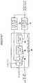
이제, 도 2를 참조하면, 제1 실시예의 전송 장치가 도시되어 있다. 동작에 있어서, I/F(인터페이스)(11)는 외부로부터 수신된 영상 데이터의 수신 처리를 수행하고, 전송/기록 디바이스(16)에 대한 코딩된 데이터의 전송 처리를 수행한다. ROM(판독 전용 메모리)(12)는 다른 항목들뿐만 아니라 IPL(Initial Program Loading)(초기 프로그램 로딩)을 위한 프로그램을 저장한다. RAM(랜덤 억세스 메모리)(13)은 외부 기록 장치(15)에 기록된 시스템 프로그램(OS(운영 체제)) 및 응용 프로그램들을 CPU(중앙 처리 장치)(14)의 동작에 있어서 필요한 데이터와 함께 저장한다. CPU(4)는 ROM(12)에 저장된 IPL 프로그램에 따라 외부 기억 장치(15)로부터 시스템 프로그램 및 응용 프로그램을 RAM(13)에 로드하여 이하의 코딩 처리가 I/F(11)로부터 공급된 영상 데이터에 대해 수행하도록 시스템 프로그램의 제어하에서 응용 프로그램을 실행한다. 외부 기억 장치(15)로는 CPU(14)에 의해 실행되는 시스템 프로그램과 응용 프로그램에 부가하여 CPU(14)의 동작에 필요한 데이터를 저장하는 예를 들면 자기 디스크 장치 등이 있다. 전송/기록 디바이스(16)는 기록 매체(2)상에 I/F(11)로부터 공급된 코딩된 데이터를 기록하거나 또는 전송 경로(3)를 거쳐 이 데이터를 전송하거나 한다.Referring now to FIG. 2, there is shown the transmitting device of the first embodiment. In operation, the I / F (interface) 11 performs reception processing of image data received from the outside, and performs transmission processing of coded data for the transmission /
I/F(11), ROM(12), RAM(13), CPU(14) 및 외부 기억 장치(15)는 버스(17)를 통해 서로 접속되어 있다.The I /
이와 같이 구성된 전송 장치(1)에서, 영상 데이터가 I/F(11)로 공급될 때, 이 영상 데이터는 CPU(14)로 공급된다. CPU(14)는 그 다음에 이 영상 데이터를 코딩하여 그 결과의 코딩된 데이터를 I/F(11)에 공급한다. I/F(11)는 그 다음에 코딩된 데이터를 수신하여 이 데이터를 전송/기록 디바이스(16)에 공급한다. 전송/기록 디바이스(16)에서, I/F(11)로부터의 코딩된 데이터는 기록 매체(2)상에 기록되거나 또는 전송 경로(3)를 거쳐 전송되거나 한다.In the
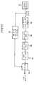
이제, 도 3, 도 4, 도 5, 도 6, 도 8, 도 11, 도 12, 도 13, 도 14, 도 15 및 도 16을 참조하여, 전송 장치(1)(전송/기록 디바이스(16)는 제외) 및 수신 장치(4)의 제1 실시예에 대해서 설명한다. 코딩될 영상 데이터(원래의 영상 데이터)는 압축 유닛(21), 로컬 디코더(22) 및 에러 계산기(23)에 공급된다. 압축 유닛(21)은 단지 픽셀을 솎아냄으로써 영상 데이터를 압축하며, 그 결과의 압축된 데이터(솎아냄 이후의 영상 데이터)는 판정 유닛(24)으로부터의 제어하에서 보정된다. 압축 유닛(21)에 의해 생성된 그 결과의 보정된 데이터는 그 다음에 로컬 디코더(22)와 판정 유닛(24)에 공급된다.Now, referring to FIGS. 3, 4, 5, 6, 8, 11, 12, 13, 14, 15, and 16, the transmission apparatus 1 (transmission / recording device 16 ), And the first embodiment of the
로컬 디코더(22)는 압축 유닛(21)으로부터의 보정된 데이터에 근거하여 원래의 영상에 대한 예측을 행하며 이 예측된 값을 에러 계산기(23)에 공급한다. 이하에 기술하는 바와 같이, 로컬 디코더(22)는 보정된 데이터와 원래의 영상 데이터를 사용하여 보정된 데이터와의 선형 결합에 의해 예측된 값을 계산하기 위하여 각 클래스에 대한 예측 계수를 얻기 위한 처리를 수행한다. 그 다음에, 로컬 디코더(22)는 이들 대응하는 예측 계수들에 근거하여 예측된 값을 얻기 위한 적응 처리를 수행하며, 이 예측된 값은 에러 계산기(23)에 공급되고 로컬 디코더(22)에 의해 생성된 각 클래스에 대한 예측 계수들은 판정 유닛(24)에 공급된다.The
에러 계산기(23)는 원래의 영상 데이터(소오스 영상 데이터)용으로 입력된 영상 데이터에 대한 로컬 디코더(22)로부터의 예측된 값의 예측 에러를 계산한다. 이 예측 에러는 그 다음에 에러 정보로서 판정 유닛(24)에 공급된다.The
판정 유닛(24)은 에러 계산기(23)로부터의 에러 정보에 근거하여 압축 유닛(21)에 의해 출력된 보정된 데이터를 원래의 영상 데이터에 대한 코딩 결과로서 취하는 것의 적합성을 판정한다. 판정 유닛(24)이 압축 유닛(21)에 의해 출력된 보정된 데이터가 원래의 영상 데이터에 대한 코딩 결과로서 취하기가 부적절하다고 판정할 때에는, 판정 유닛(24)은 압축 유닛(21)을 제어하여 압축된 데이터를 보정하고, 그 결과의 새로운 보정된 데이터가 출력된다. 판정 유닛(24)이 압축 유닛(21)에 의해 출력된 보정된 데이터가 원래의 영상 데이터에 대한 코딩 결과로서 취하기에 적합한 것으로 판정할 때에는, 압축 유닛(21)으로부터 공급된 보정된 데이터는 최적의 보정된 데이터(optimum corrected data)(이후부터는 간략함을 위해 "최적의 보정된 데이터"라고 함)로서 멀티플렉서(25)에 공급된다. 로컬 디코더(22)로부터 공급된 예측 계수도 멀티플렉서(25)에 공급된다.The
멀티플렉서(25)는 판정 유닛(24)으로부터의 최적 데이터(보정된 데이터)와 각 클래스에 대한 예측 데이터를 멀티플렉싱하여 이 멀티플렉싱의 결과를 전송/기록 디바이스(도 2)에 코딩된 데이터로서 출력한다.The
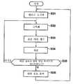
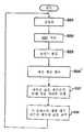
이제, 도 4의 플로우챠트를 참조하여 이 동작에 대해서 기술한다. 영상 데이터가 압축 유닛(21)에 공급될 때, 단계(S1)에서, 압축 유닛(21)은 이 영상 데이터를 솎아냄으로써 압축을 수행하고, 이 영상 데이터를 보정을 행하지 않고 로컬 디코더(22) 및 판정부(24)로 먼저 출력한다. 보정된 데이터(초기에 이것은 영상 데이터가 단순히 솎아내어진 압축된 데이터임)가 단계(S2)에서 로컬 디코더(22)에서 국부적으로 디코딩된다.This operation will now be described with reference to the flowchart in FIG. When the image data is supplied to the
즉, 단계(S2)에서, 보정된 데이터와 원래의 영상 데이터를 사용하여 압축 유닛(21)으로부터의 보정된 데이터와의 선형 결합에 의해 원래의 영상 데이터에 대한 예측된 값을 계산하기 위하여 각 클래스에 대한 예측 계수를 얻기 위한 처리가 수행되고, 이들 예측 계수들에 근거하여 예측된 값을 얻기 위해 적응 처리가 수행된다. 로컬 디코더(22)에 의해 생성된 예측 값은 그 다음에 에러 계산기(23)에 공급되고, 로컬 디코더(22)에 의해 생성된 예측 계수들은 판정부(24)에 공급된다.That is, in step S2, each class is calculated in order to calculate a predicted value for the original image data by linear combination of the corrected data from the
로컬 디코더(22)로부터 출력된 예측된 값들로 이루어진 영상은 수신 장치(4)(도 1) 측에서 얻어진 디코딩된 영상과 동일하다.The image made up of the predicted values output from the
원래의 영상 데이터에 대한 예측된 값이 로컬 디코더(22)로부터 수신될 때, 에러 계산기(23)는 단계(S3)에서 원래의 영상 데이터에 대한 로컬 디코더(22)로부터의 예측된 값의 추정 에러(estimation error)를 계산하여 이 예측 에러를 판정 유닛(24)에 에러 정보로서 공급한다. 에러 정보가 에러 계산기(23)로부터 수신될 때, 단계(S4)에서, 판정 유닛(24)는 압축 유닛(21)에 의해 출력된 보정된 데이터가 이 에러 정보에 근거하여 원래의 영상 데이터에 대한 코딩 결과로서 취하기에 적합한지 여부를 판정한다.When the predicted value for the original image data is received from the
즉, 단계(S4)에서, 에러 정보가 미리 정해진 임계값 ε보다 더 작은지 여부에 대한 판정을 행한다. 단계(S4)에서 에러 정보가 미리 정해진 임계값 ε보다 더 작지 않은 것으로 판정될 때에는, 압축 유닛(21)에 의해 출력된 보정된 데이터는 원래의 영상 데이터에 대한 코딩된 데이터로서 부적절한 것으로 판명되며, 단계(S5)로 진행하여 판정 유닛(24)는 압축된 데이터를 보정하도록 압축 유닛(21)을 제어한다. 압축 유닛(21)은 그 다음에 판정 유닛(24)의 제어하에서 보정량(correction amount)(이후부터는 보정된 값 Δ라고 함)을 변경하고, 압축된 데이터는 보정되며 그 결과의 보정된 데이터는 로컬 디코더(22) 및 판정 유닛(24)으로 출력된다. 단계(S2)로 그 다음에 복귀하여 동일한 프로세스가 그 후에 반복된다.That is, in step S4, a determination is made as to whether or not the error information is smaller than the predetermined threshold value [epsilon]. When it is determined in step S4 that the error information is not smaller than the predetermined threshold value?, The corrected data output by the
반면에, 단계(S4)에서 에러 정보가 미리 정해진 임계값 ε보다 작은 것으로 판정될 때에는, 압축 유닛(21)에 의해 출력된 보정된 데이터는 원래의 영상 데이터에 대한 코딩 결과로서 적합한 것으로 판명된다. 판정 유닛(24)은 그 다음에 에러 정보가 미리 정해진 임계값 ε보다 작을 때에 얻어진 보정된 데이터를 각 클래스에 대한 예측 계수들과 함께 최적의 압축된 데이터로서 멀티플렉서(25)에 출력한다. 멀티플렉서(25)에서는, 단계(S6)에서, 판정 유닛(24)으로부터의 최적의 압축된 데이터와 각 클래스에 대한 예측 계수들이 멀티플렉싱되고, 그 결과의 코딩된 데이터가 출력되며 프로세스가 완료된다.On the other hand, when it is determined in step S4 that the error information is smaller than the predetermined threshold value?, The corrected data output by the
상술한 바와 같이, 에러 정보가 미리 정해진 임계값 ε보다 더 작을 때 압축 데이터로부터의 보정된 데이터는 원래의 영상 데이터에 대한 코딩된 결과로서 취해진다. 원래의 영상 데이터(소오스 영상 데이터)와 거의 동일한 영상이 이 보정된 데이터에 근거하여 수신 장치(4) 측에서 얻어질 수 있다.As described above, the corrected data from the compressed data when the error information is smaller than the predetermined threshold value epsilon is taken as a coded result for the original image data. An image almost identical to the original image data (source image data) can be obtained on the receiving
다음에는, 압축 유닛(21)의 구성의 일례가 도 5에 도시되어 있다.Next, an example of the structure of the
여기에서, 인코딩될 영상 데이터가 솎아냄 유닛(thinning-out unit)(31)에 입력된다. 솎아냄 유닛(31)은 그 다음에 1/N로 압축된 압축 데이터가 솎아냄 유닛(31)으로부터 출력되도록 영상 데이터를 1/N로 솎아낸다. 이 압축된 데이터는 그 다음에 솎아냄 유닛(31)으로부터 보정 유닛(32)로 공급된다.Here, video data to be encoded is input to a thinning-out
보정 유닛(32)는 그 다음에 보정된 값 Δ가 판독되도록 판정 유닛(24)(도 3)으로부터의 제어 신호에 따라서 보정된 값 ROM(33)에 어드레스를 제공한다. 보정 유닛(32)는 그 다음에 예를 들면 보정된 값 ROM(33)으로부터의 보정된 값 Δ를 솎아냄 유닛(31)으로부터의 압축된 데이터에 가산함으로써 보정된 데이터를 생성한다. 이 보정된 데이터는 그 다음에 로컬 디코더(22) 및 판정 유닛(24)에 공급된다. 여러 가지 보정된 값 Δ 각각의 결합(예를 들면 압축된 데이터의 한 프레임 부분을 보정하기 위한 보정된 값들의 결합)이 그 다음에 솎아냄 유닛(31)에 의해 출력된 압축된 데이터를 보정하기 위하여 보정된 값 ROM(33)에 의해 저장된다. 보정 유닛(32)로부터 공급된 어드레스에 대응하는 보정된 값 Δ의 결합은 그 다음에 판독되어 보정 유닛(32)에 공급된다.The
다음에는, 도 5의 압축 유닛(21)에 대한 프로세스에 대해서 도 6을 참조하여 설명한다.Next, a process for the
예를 들면, 영상 데이터의 한 프레임 부분 등이 솎아냄 유닛(31)에 공급될 때, 솎아냄 유닛(31)은 단계(S11)에서 이 영상 데이터를 1/N로 솎아내고 그 결과의 압축된 데이터가 보정 유닛(32)로 출력된다.For example, when one frame portion or the like of the image data is supplied to the thinning
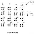
도 7에 도시한 바와 같이, 솎아냄 유닛(31)은 예를 들면 1/9로 영상 데이터를 솎아낸다. 즉, 솎아냄 유닛(31)은 각 유닛의 중심에 있는 픽셀들(도 7에서 ●로서 표시됨)에 대한 픽셀값들만을 추출하여 3 x 3(수평 x 수직)으로 배열된 9개의 픽셀을 한 단위로 취하고 다른 부분들(도 7에서 ○로 표시됨)을 제거된다. 솎아냄 유닛(31)은 그 다음에 예를 들면 한 프레임(필드) 단위의 단위로서 상기의 프로세스를 수행한다. 한 프레임에 대한 영상 데이터가 1/9로 솎아내어진 압축된 데이터는 따라서 솎아냄 유닛(31)으로부터 보정 유닛(32)로 공급된다. 또한, 한 프레임의 영상이 몇 개의 블록으로 분할되어 솎아냄 유닛에서 일어나는 솎아냄 처리가 이들 블록의 단위로 수행될 수 있다.As shown in Fig. 7, the thinning
압축된 데이터가 솎아냄 유닛(31)으로부터 수신될 때, 단계(S12)에서는 보정 유닛(32)은 제어 신호가 판정 유닛(24)(도 3)으로부터 수신되었는지 여부에 관한 판정을 행하고, 제어 신호가 수신된 경우에는 제어 신호는 "동작의 끝"을 나타내는 상태를 가진다. 제어 신호가 단계(S12)에서 수신되지 않은 것으로 판정될 때에는, 단계(S15)로 진행된다. 보정 유닛(32)은 그 다음에 솎아냄 유닛으로부터 로컬 디코더(22) 및 판정 유닛(24)으로 압축된 데이터를 수정없이 보정된 데이터로서 출력하며, 단계(S12)로 복귀한다.When the compressed data is received from the thinning
즉, 상기한 바와 같이, 판정 유닛(24)은 에러 정보에 근거하여 압축 유닛(21)(보정 유닛(32))을 제어한다. 그 다음에, 압축된 데이터가 솎아냄 유닛(31)으로부터 출력된 직후에, 제어 신호는 판정 유닛(24)으로부터 출력되지 않는데, 그 이유는 에러 정보를 얻을 수 없기 때문이다(에러 정보가 에러 계산기(23)로부터 출력되지 않기 때문이다). 따라서, 압축된 데이터가 솎아냄 유닛(31)으로부터 출력된 직후에, 보정 유닛(32)은 이 압축된 데이터(제로 부가(adding zero)의 보정이 수행됨)를 보정하지 않고 이 데이터는 수정없이 로컬 디코더(22) 및 판정 유닛(24)에 보정된 데이터로서 출력된다.That is, as described above, the
반면에, 단계(S12)에서 제어 신호가 판정 유닛(24)으로부터 수신된 것으로 판정될 때에는, 단계(S13)에서 보정 유닛(32)은 이 제어 신호에 따른 어드레스를 보정된 값 ROM(33)으로 출력한다. 이 결과, 단계(S13)에서, 이 어드레스에 저장된 압축된 데이터의 한 프레임 부분을 보정하기 위한 보정된 값 Δ의 결합(집합)이 ROM(33)으로부터 판독되어 보정 유닛(32)에 공급된다. 보정된 값들 Δ의 결합이 보정된 값 ROM(33)으로부터 수신될 때에는, 단계(S14)에서 보정 유닛(32)은 압축된 데이터에 대해 보정된 보정 데이터를 계산하기 위하여 압축된 데이터의 한 프레임 각각에 대응하는 보정된 값 Δ을 가산한다. 이 후에, 단계(S15)로 진행하고, 보정된 데이터가 보정 유닛(32)으로부터 로컬 디코더(22) 및 판정 유닛(24)으로 출력되며 단계(S12)로 복귀한다.On the other hand, when it is determined in step S12 that the control signal has been received from the
단계(S12)에서 동작의 끝 상태를 갖는 제어 신호가 판정 유닛(24)으로부터 수신된 것으로 판정될 때에는, 프로세스는 단계(S11)로 복귀하여 솎아냄 유닛(31)은 단계(S11)에서 영상 데이터를 1/N으로 솎아내고, 그 다음에 오는 프레임에 대한 그 결과의 압축된 데이터가 이 플로우챠트에 따라 처리된다.When it is determined in step S12 that the control signal having the end state of operation has been received from the
상술한 바와 같이, 압축 유닛(21)은 판정 유닛(24)의 제어하에서 여러 가지 값으로 보정된 압축 데이터에 대한 보정된 데이터를 반복하여 출력한다.As described above, the
한 프레임의 영상에 대해 코딩이 완료될 때, 판정 유닛(24)은 이 지점을 나타내는 제어 신호를 압축 유닛(21)에 공급한다. 압축 유닛(21)이 단계(S12)에서 이 제어 신호를 수신할 때에는, 현재의 프레임에 대한 프로세스가 끝나게 되고, 도 6의 플로우챠트에 따른 프로세스가 그 다음에 오는 프레임에 대한 영상에 대해 실행된다.When coding is completed for an image of one frame, the
상기한 경우에, 3 x 3으로 배열된 픽셀의 중심에 있는 픽셀에 대한 픽셀 데이터(픽셀 값)만이 솎아냄 유닛(31)에서 추출되어 압축된 데이터를 생성하게 된다. 그러나, 예를 들면, 3 x 3 픽셀에 대한 평균값도 계산할 수 있으며, 3 x 3 픽셀이 중심에 있는 픽셀에 대한 픽셀 값으로서 이 평균값을 취하여 압축된 데이터가 생성될 수 있다.In the above case, only the pixel data (pixel value) for the pixel at the center of the pixel arranged in 3 x 3 is extracted in the thinning
도 8은 도 3의 로컬 디코더(22)의 구성의 일례를 나타낸 것이다.8 shows an example of the configuration of the
압축 유닛(21)으로부터의 보정된 데이터는 클래스 분류를 위한 블록화 유닛(41) 및 예측된 값 계산을 위한 블록화 유닛(42)에 공급된다. 클래스 분류를 위한 블록화 유닛(41)은 그 다음에 보정된 데이터의 특성에 따라 보정된 데이터를 미리 정해진 클래스로 분류하기 위한 단위가 되는 주지의 보정된 데이터를 중심으로 클래스 분류를 위한 블록의 형태로 만든다.The corrected data from the
즉, 도 7에서, 위로부터 i 번째와 좌로부터 j 번째의 보정된 데이터(압축된 데이터)(또는 픽셀)(도 7에 표시 ●로 도시된 부분)을 Xij로 표현할 때, 클래스 분류를 위한 블록화 유닛(41)은 표시된 픽셀 Xij와 표시된 픽셀의 좌상측, 상측, 우상측, 좌측, 우측, 좌하측, 하측 및 우하측의 8개의 픽셀 X(i-1)(j-1), X(i-1)j, X(i-1)(j+1), Xi(j-1), Xi(j+1), X(i-1)(j-1), X(i-1)j, X(i+1)(j+1)의 총 9개의 픽셀로 이루어진 클래스 분류 블록을 구성한다. 이 클래스 분류 블록은 그 다음에 클래스 분류 적응 처리 회로(43)에 공급된다.That is, in FIG. 7, when representing the corrected data (compressed data) (or pixels) (the part shown by ● in FIG. 7) from the i th from the top and the j th from the left, Xij is used for class classification. The blocking
이 경우에, 클래스 분류 블록은 3 x 3 픽셀이 정사각형 블록을 구성하지만, 클래스 분류 블록의 형상은 정사각형일 필요는 없으며 예를 들면 직사각형, 십자가 모양 또는 다른 임의의 형상일 수 있다. 클래스 분류 블록을 구성하는 픽셀의 수도 또한 결코 3 x 3 픽셀 블록의 9개의 픽셀로 제한되지도 않는다.In this case, the class classification block constitutes a square block of 3 x 3 pixels, but the shape of the class classification block need not be square and may be, for example, rectangular, cross-shaped or any other shape. The number of pixels that make up the class classification block is also never limited to nine pixels of a 3 x 3 pixel block.
예측된 값 계산을 위한 블록화 유닛(42)은 보정된 데이터를 원래의 영상 데이터에 대한 예측된 값을 계산하기 위한 단위가 되는 주지의 보정된 데이터를 중심으로 예측된 값에 대한 블록의 형태로 만든다. 즉, 도 7에서, 픽셀 Yij(1)내지 Yij(1)에 대한 예측된 값을 계산하기 위하여 보정된 데이터 Xij(도 7에 ●로 도시된 부분)를 중심으로 취하고 원래의 영상 데이터(소오스 화상 데이터)에서 일어나는 3 x 3의 9개의 픽셀 데이터를 Yij(1), Yij(2), Yij(3), Yij(4), Yij(5), Yij(6), Yij(7), Yij(8), Yij(9)로 표현하게 되면, 예측된 값 계산을 위한 블록화 회로(42)는 예를 들면 5 x 5 행렬로서 픽셀 Xij을 중심으로 25개의 픽셀 X(i-2)(j-2), X(i-2)(j-1), X(i-2)j, X(i-2)(j+1), X(i-2)(j+2), X(i-1)(j-2), X(i-1)(j-1), X(i-1)j, X(i-1)(j+1), X(i-1)(j+2), Xi(j-2), Xi(j-1), Xij, Xi(j+1), Xi(j+2), X(i+1)(j-2), X(i+1)(j-1), X(i+1)j, X(i+1)(j+1), X(i+1)(j+2), X(i+2)(j-2), X(i+2)(j-1), X(i+2)j, X(i+2)(j+1), 및 X(i+2)(j+2)로 이루어진 예측된 값 계산용 정사각형 블럭을 구성한다.Blocking
특히, 예를 들면 추정 에러 계산용 블록은 도 7에 4변형 모양에 의해 둘러싸인 원래의 영상에 대한 영상에서 일어나는 9개의 픽셀 Y33(1)' 내지 Y33(9)'에 대한 예측된 값을 계산하기 위하여 픽셀 X11', X12', X13', X14', X15', X21', X22', X23', X24', X25', X31', X32', X33', X34', X35', X41', X42', X43', X44', X45', X51', X52', X53', X54', 및 X55' 로 구성된다.In particular, the estimation error calculation block, for example, shows predicted values for the nine pixels Y33 (1) ' to Y33 (9)' occurring in the image for the original image surrounded by the quadrilateral shape in FIG. To calculate pixels X11 ' , X12' , X13 ' , X14' , X15 ' , X21' , X22 ' , X23' , X24 ' , X25' , X31 ' , X32 ' , X33' , X34 ' , X35' , X41 ' , X42' , X43 ' , X44' , X45 ' , X51' , X52 ' , X53' , X54 ' , And X55 ' .
예측된 값 계산을 위한 블록화 회로(42)에서 얻은 예측된 값 계산에 사용하기 위한 블록은 클래스 분류 적응 처리 회로(43)에 공급된다.The block for use in calculating the predicted value obtained in the blocking
클래스 분류용 블록들의 경우에서와 같이 예측된 값 계산용 블록의 형상 및 픽셀의 수도 상기에 의해 한정되지 않는다. 그러나, 예측된 값 계산을 위한 블록을 구성하는 픽셀의 수를 클래스 분류용 블록을 구성하는 픽셀의 수보다 크게 하는 것이 보다 양호하다.As in the case of the class classification blocks, the shape of the predicted value calculation block and the number of pixels are not limited thereto. However, it is better to make the number of pixels constituting the block for calculating the predicted value larger than the number of pixels constituting the block for class classification.
상기한 블록화가 수행되어(이것은 블록화 프로세스 이외의 프로세스에 대해서는 동일함) 영상에 대한 화상 프레임의 근처에 대응하는 픽셀이 없을 때에는, 프로세스는 예를 들면 화상 프레임을 구성하는 픽셀과 동일 픽셀이 외부에 존재할지라도 수행된다.When the above-described blocking is performed (this is the same for processes other than the blocking process) and there are no corresponding pixels in the vicinity of the image frame for the image, the process is performed by the same pixel as the pixel constituting the image frame, for example. Even if it exists.
클래스 분류 적응 처리 유닛(43)은 ADRC(적응형 다이나믹 레인지 코딩)(Adaptive Dynamic Range Coding) 처리 유닛(44), 클래스 분류 유닛(45) 및 적응 처리 유닛(46)을 포함하며 클래스 분류 적응 처리를 수행한다.The class classification
클래스 분류 적응 처리는 입력 신호를 입력 신호의 특성에 근거하여 다수의 클래스로 분류한 다음에 각 클래스에 대해 적절한 적응 처리를 실행한다. 클래스 분류 적응 처리는 따라서 크게 클래스 분류 처리와 적응 처리로 나눌 수 있다.The class classification adaptation process classifies the input signal into a plurality of classes based on the characteristics of the input signal, and then performs appropriate adaptation processing for each class. The class classification adaptation process can thus be broadly divided into the class classification process and the adaptation process.
여기에서, 클래스 분류 처리와 적응 처리에 대해 간단하게 기술한다.Here, the class classification process and the adaptive process will be briefly described.
먼저, 클래스 분류 처리에 대해서 기술한다.First, class classification processing will be described.
도시된 바와 같이, 예를 들면 설명을 간단하게 하기 위해, 도 9a에서, 블록은 어떤 주지 픽셀과 이 주지 픽셀에 이웃하는 3개의 픽셀을 사용하여 2 x 2 픽셀(클래스 분류용 블록)로 구성되며, 각 픽셀은 1 비트(0 또는 1의 레벨)로 표현되도록 한다. 이 경우, 2 x 2의 4 픽셀 블록은 픽셀 레벨의 각각의 분포를 사용하여 도 9b에 도시된 바와 같이 16(=(21)4)개의 패턴으로 분류된다. 이러한 종류의 패턴 분할이 클래스 분류 프로세스이며 클래스 분류 유닛(45)에 의해 수행된다.As shown, for example, for simplicity of explanation, in FIG. 9A, a block is composed of 2 x 2 pixels (block for class classification) using a certain pixel and three pixels neighboring the pixel. Each pixel is represented by one bit (a level of zero or one). In this case, 2 x 2 4 pixel blocks are classified into 16 (= (21 )4 ) patterns as shown in FIG. 9B using respective distributions of pixel levels. This kind of pattern division is a class classification process and is performed by the
클래스 분류 프로세스는 영상(블록내의 영상)의 활동(영상 복잡성)을 고려하도록 수행될 수 있다(변경의 엄격성).The class classification process may be performed to take into account the activity (picture complexity) of the picture (picture in the block) (stringency of change).
보통, 예를 들면, 약 8 비트가 각 픽셀에 할당된다. 게다가, 이 실시예에서는, 상기한 바와 같이, 클래스 분류 블록은 3 x 3의 9 픽셀로 이루어져 있다. 따라서, 클래스 분류 처리가 이러한 종류의 클래스 분류용 블록을 목표로 수행되기 때문에, 엄청난 수(28)9의 클래스를 분류할 수 있다.Normally, for example, about 8 bits are allocated to each pixel. In addition, in this embodiment, as described above, the class classification block consists of 9 pixels of 3 x 3. Therefore, since the class classification process is performed for this kind of class classification block, it is possible to classify a huge number (28 )9 classes.
이 실시예에서, ADRC 처리가 ADRC 처리 유닛(44)에서 클래스 분류용 블록에 대해 수행된다. 그런 다음에 클래스의 수는 클래스 분류용 블록으로 이루어진 픽셀에 대한 비트 수를 작게 함으로써 감소될 수 있다.In this embodiment, ADRC processing is performed on the class classification block in the
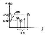
예를 들어, 설명의 간략함을 위해, 도 10a에 도시된 바와 같이, 직선상에 늘어선 4개의 픽셀로 이루어진 블록을 생각해보면, 이들 픽셀에 대한 최대값 MAX와 최소값 MIN이 ADRC 처리에서 검출된다. 그런 다음에 DR = MAX - MIN이 블록의 국부화된 다이나믹 레인지로서 취해지고, 이 블록을 구성하는 픽셀들의 픽셀 값이 이 다이나믹 레인지 DR에 근거하여 K 비트로 재양자화된다.For example, for simplicity of explanation, considering a block of four pixels lined up in a straight line, as shown in FIG. 10A, the maximum value MAX and minimum value MIN for these pixels are detected in the ADRC process. DR = MAX-MIN is then taken as the localized dynamic range of the block, and the pixel values of the pixels that make up the block are re-quantized to K bits based on this dynamic range DR.
즉, 최소값 MIN이 블록내의 각 픽셀에 대한 값으로부터 감산되고, 이 감산된 값은 DR/2K로 나누어져 그 결과의 나누어진 값에 대응하는 코드로 변환된다. 특히, 예를 들면 K=2일 때에는 도 10b에 도시된 바와 같이 나누어진 값은 다이나믹 레인지 DR을 4(=22)개의 같은 부분으로 나누며, 그 픽셀값이 어느 레인지에 속하는지에 대한 판정이 있게 된다. 나누어진 값이 최하위 레벨의 레인지, 두번째 최하위 레벨의 레인지, 세번째 최하위 레벨의 레인지 또는 최상위 레벨의 레인지에 속할 때에는, 예를 들면 제각기 00B, 01B, 10B, 또는 11B(B는 이진수를 나타냄)의 2 비트로의 코딩이 수행된다. 도 10b에 도시된 바와 같이, 그 다음에 ADRC 코드 00B, 01B, 10B 및 11B를 최하위 레벨에 대한 레인지에 대해서는 중심값 L00으로, 두번째 최하위 레벨에 대한 레인지에 대해서는 중심값 L01로, 세번째 최하위 레벨에 대한 레인지에 대해서는 중심값 L10으로, 최상위 레벨에 대한 레인지에 대해서는 중심값 L11로 변환함으로써 디코딩측에서 디코딩이 수행된다. 그런 다음에 최소값 MIN이 이 값에 가산된다. 이러한 종류의 ADRC 처리를 논-에지 매칭(non-edge matching)이라고 한다.That is, the minimum value MIN is subtracted from the value for each pixel in the block, and this subtracted value is divided by DR / 2K and converted into a code corresponding to the resulting divided value. In particular, for example, when K = 2, the divided value divides the dynamic range DR into 4 (= 22 ) equal parts as shown in FIG. 10B, so that there is a determination as to which range the pixel value belongs to. do. When the divided values belong to the lowest level range, the second lowest level range, the third lowest level range, or the highest level range, for example, 00B, 01B, 10B, or 11B (B represents binary), respectively. Coding to bits is performed. As shown in FIG. 10B, ADRC codes 00B, 01B, 10B and 11B are then set to center value L00 for the range for the lowest level, to center value L01 for the range for the second lowest level, and to the third lowest level. The decoding is performed on the decoding side by converting the range with respect to the center value L10 and the range with respect to the highest level with the center value L11. The minimum value MIN is then added to this value. This kind of ADRC processing is called non-edge matching.
개선된 논-에지 매칭 방법이 도 10c에 의해 도해되어 있다. 이 개선된 타입의 논-에지 매칭에서는, 다이나믹 레인지 DR이 4개의 같은 부분으로 나누어지며, 최하위 레벨의 레인지에 속하는 픽셀 값에 대한 평균값 MIN'과 최상위 레벨의 레인지에 속하는 픽셀값에 대한 평균값 MAX'은 ADRC 코드 00B와 11B로 변환된다. MAX'-MIN'에 의해 정의된 다이나믹 레인지 DR'을 (3개의 동일한 부분으로) 나누는 레벨들은 ADRC 코드 01B와 10B로 변환되어 ADRC 디코딩이 수행되게 된다. 이것이 ADRC 처리를 개선한 것이다.An improved non-edge matching method is illustrated by FIG. 10C. In this improved type of non-edge matching, dynamic range DR is divided into four equal parts, the average value MIN 'for pixel values in the lowest level range and the MAX value for pixel values in the highest level range. Is converted to ADRC codes 00B and 11B. Levels dividing the dynamic range DR '(defined into three equal parts) defined by MAX'-MIN' are converted to ADRC codes 01B and 10B, so that ADRC decoding is performed. This is an improvement on ADRC processing.
이 ADRC 처리는 예를 들면 일본 특허 공보 3-53778호에 자세히 개시되어 있다.This ADRC process is disclosed in detail in Japanese Patent Publication No. 3-53778, for example.
클래스 수는 블록을 구성하는 픽셀에 할당된 비트 수보다 작은 비트 수로 재양자화함으로써 ADRC 처리를 수행하여 상기의 방식으로 감소될 수 있으며, 이러한 종류의 ADRC 처리는 ADRC 처리 유닛(44)에서 수행된다.The number of classes can be reduced in the above manner by performing ADRC processing by requantizing to a number of bits smaller than the number of bits allocated to the pixels constituting the block, and this kind of ADRC processing is performed in the
이 실시예에서, 클래스 분류는 ADRC 처리 유닛(44)으로부터 출력된 ADRC 코드에 근거하여 클래스 분류 유닛(45)에서 수행된다. 그러나, 클래스 분류 처리는 또한 예를 들면 DPCM(추정 코딩)(estimation coding), BTC(블럭 트렁케이션 코딩)(Block Truncation Coding), 벡터 양자화(VQ)(Vector Quantization), DCT(이산 코사인 변환)(Discrete Cosine Transform) 및 아다마르 변환 코딩(Adamar Transform coding)이 수행되는 목적 데이터(object data)로서 취하여 수행될 수 있다.In this embodiment, class classification is performed in the
다음에는, 적응 처리에 대해서 설명한다.Next, the adaptive processing will be described.
예를 들면, 원래의 영상 데이터에 대한 픽셀 값 y의 예측된 값 E[y]는 이 근처에 있는 몇개의 픽셀에 대한 픽셀 값(이 실시예에서는, 보정된 데이터, 이후부터는 학습 데이터(learning data)라고 함) x1, x2, ...와 미리 정해진 예측 계수 w1, w2, ...에 의해 정의된 선형 1차 결합 모델을 사용하여 얻을 수 있는 것으로 생각된다. 이 경우에, 예측된 값 E[y]는 이하의 식으로 나타난다.For example, the predicted value E [y] of the pixel value y for the original image data is the pixel value for some nearby pixels (in this embodiment, the corrected data, and subsequently the learning data). It is thought that it can be obtained using the linear first-order combined model defined by x1 , x2 , ... and the predetermined prediction coefficients w1 , w2 , .... In this case, the predicted value E [y] is represented by the following formula.
일반화시키기 위해, 예측 계수 w에 대한 집합인 행렬 W, 학습 데이터에 대한 집합인 어레이 X 및 예측된 값 E[y]에 대한 집합인 어레이 Y'은 다음과 같이 정의된다:For generalization, the matrix W, the set of prediction coefficients w, the array X, the set of training data, and the array Y ', the set of predicted values E [y], are defined as follows:


이하 시행되는 수학식은 다음과 같이 될 수 있다.Equation implemented below may be as follows.
원래의 영상 데이터의 픽셀 값 y 근처에서의 예측된 값 E[y]는 이 시행 방정식에 최소 제곱법을 적용함으로써 얻을 수 있다. 이 경우에, 원래의 영상 데이터에 대한 영상에 대한 픽셀 값에 대한 집합인 행렬 Y와 원래의 영상 데이터에 대한 영상 값 y에 대한 예측된 값 E[y]에 대한 나머지 e에 대한 집합인 행렬 E가 다음과 같이 정의될 때:The predicted value E [y] near the pixel value y of the original image data can be obtained by applying the least square method to this trial equation. In this case, matrix E, which is the set of matrix Y for the pixel values for the image for the original image data, and matrix E, which is the set for the remaining e for the predicted value E [y], for the image value y for the original image data Is defined as:


이하의 나머지 수학식은 수학식 2로부터 다음과 같이 될 수 있다.The remaining equations below may be as follows from equation (2).
원래의 영상 데이터에 대한 픽셀 값 y에 가까운 예측된 값 E[y]를 얻기 위하여 원래의 영상 데이터에 대한 예측 계수 wi가 최소 에러를 만들도록 얻어질 수 있다.In order to obtain the predicted value E [y] close to the pixel value y for the original image data, the prediction coefficient wi for the original image data can be obtained to make the minimum error.

따라서, 예측 계수 wi에 의해 차분화된 제곱 에러(square error differentiated by the predictive coefficient)가 영으로 된다, 즉 이하의 수학식을 만족시키는 예측 계수 wi가 원래의 영상 데이터에 대한 픽셀 값 y에 가까운 예측된 값 E[y]를 얻는데 가장 적합한 값이다.Therefore, the square error differentiated by the predictive coefficient becomes zero by the prediction coefficient wi, that is, the prediction coefficient wi that satisfies the following equation is predicted closer to the pixel value y for the original image data. This is the best value to get the value E [y].

여기에서, 이하의 수학식은 예측 계수 wi에 의한 차분화 수학식 3에 의해 먼저 다음과 같이 된다.Here, the following equation is first expressed as follows by the

수학식 6은 다음에 수학식 4와 수학식 5로부터 얻어진다.

이하의 정규 방정식(regular equation)은 나머지 수학식 3의 학습 데이터 x, 예측 계수 w, 교수 데이터(teacher data) y 및 나머지 e 사이의 관계를 고려하여 수학식 6으로부터 얻어질 수 있다.The following regular equation may be obtained from

수학식 7의 정규 방정식은 얻어질 예측 계수 w의 수와 동일한 수만을 갖는다. 가장 적합한 예측 계수 w는 수학식 7의 해를 구함으로써 얻어질 수 있다. 수학식 7은 예를 들면 릴리스법(release method)등(가우스 조단 소거법(Gauss Jordan elimination method) 등)을 적용함으로써 해를 구할 수 있다.The regular equation of equation (7) has only the same number as the number of prediction coefficients w to be obtained. The most suitable prediction coefficient w can be obtained by solving the equation (7).
이상의 적응 처리로 각 클래스에 가장 적합한 예측 계수 w가 얻어지며, 원래의 영상 데이터에 대한 픽셀 값 y에 가까운 예측된 값 E[y]는 이 예측 계수 w를 사용하여 수학식 1로부터 얻어진다. 이 적응 처리는 적응 처리 유닛(46)에서 수행된다.The above adaptive processing yields the best prediction coefficient w for each class, and the predicted value E [y] close to the pixel value y for the original image data is obtained from equation (1) using this prediction coefficient w. This adaptation process is performed in the
적응 처리는 원래의 영상에는 포함되어 있으나 솎아낸 영상에 포함되어 있지 않은 성분들이 재생된다는 점에서 보간 처리와 다르다. 즉, 단지 수학식 1이 적응 처리에서 이용되는 경우, 이것은 소위 보간 필터를 사용하는 보간 처리와 동일하다. 그러나, 이 보간 필터의 탭 수에 대응하는 예측 계수 w는 교수 데이터 y를 사용하는 소위 학습을 사용하여 얻어지기 때문에, 원래의 영상 데이터에 포함된 성분들을 재생할 수 있다. 적응 처리는 소위 영상을 재생하는 동작인 프로세스라고 말할 수 있다.Adaptive processing differs from interpolation in that components that are included in the original image but not included in the subtracted image are reproduced. That is, if only
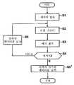
다음에는, 도 11의 플로우챠트를 참조하여 도 8의 로컬 디코더(22)의 동작에 대해서 설명한다.Next, the operation of the
먼저, 단계(S21)에서, 로컬 디코더(22)는 압축 유닛(21)으로부터의 보정된 데이터를 블록의 형태로 만든다. 즉, 클래스 분류를 위한 블록화 회로(41)에서, 보정된 데이터는 클래스 분류용의 주지의 보정된 데이터를 중심으로 3 x 3 픽셀 블럭의 형태로 만들어져 클래스 분류 적응 처리 회로(43)에 공급된다. 게다가, 예측된 값 계산을 위한 블록화 회로(42)에서는, 보정된 데이터가 예측된 값 계산을 위한 주지의 보정된 데이터를 중심으로 5 x 5 픽셀 블록의 형태로 만들어져 클래스 분류 적응 처리 회로(43)에 공급된다.First, in step S21, the
원래의 영상 데이터에 대한 영상 데이터도 또한 클래스 분류용 블록과 예측된 값 계산을 위한 블록에 부가하여 클래스 분류 적응 처리 회로(43)에 공급된다. 클래스 분류용 블록은 ADRC 처리 유닛(44)에 공급되고, 예측된 값 계산용 블록과 원래의 영상 데이터에 대한 영상 데이터는 적응 처리 유닛(46)에 공급된다.Image data for the original image data is also supplied to the class classification
단계(S22)에서, 클래스 분류를 위한 블록이 수신될 때, ADRC 처리 유닛(44)은 클래스 분류용 블록을 예를 들면 1 비트 ADRC(ADRC는 1 비트 양자화를 사용하여 수행됨) 처리하여 보정된 데이터를 1 비트로 변환(코딩)하여 클래스 분류 유닛(45)으로 출력한다. 단계(S23)에서, 클래스 분류 유닛(45)은 ADRC 처리된 클래스 분류용 블록을 클래스 분류 처리하게 된다. 즉, 클래스 분류 유닛(45)은 블록내의 각 레벨의 분포 상태를 검출하여 이들 클래스 분류 블록이 속하는 클래스를 판정한다. 이 클래스 판정의 결과는 적응 처리 유닛(46)에 클래스 정보로서 공급된다.In step S22, when a block for class classification is received, the
이 실시예에서, 클래스 분류용 블록 각각은 512(=(21)9) 클래스 중 하나에 속하는데 그 이유는 클래스 분류 분할이 1-비트 ADRC 처리를 받은 3 x 3으로 배열된 9개의 픽셀을 구성하는 클래스 분류를 위한 블록에 대해 수행되었기 때문이다.In this embodiment, each class classification block belongs to one of the 512 (= (21 )9 ) classes because the class classification division is comprised of nine pixels arranged in 3 x 3 that have undergone 1-bit ADRC processing. This is because it is performed on the blocks for classifying the constituent classes.
그 다음에 단계(S24)로 진행하며 각 클래스에 대한 예측 계수들과 1 프레임의 원래의 영상 데이터에 대한 예측된 값을 계산할 수 있도록 클래스 분류 유닛(45)으로부터의 클래스 정보에 근거하여 각 클래스에 대해 적응 처리 유닛(46)에서 적응 처리가 수행된다.The process then proceeds to step S24, in which each class is based on the class information from the
즉, 이 실시예에서, 각 클래스에 대한 25 x 9 예측 계수들은 어떤 보정된 데이터를 주지의 데이터로서 취할 때 보정된 데이터와 1 프레임에 대한 원래의 영상 데이터를 사용하여 계산된다. 이 주지의 보정된 데이터에 대응하는 픽셀과 이 픽셀을 둘러싸는 8개의 픽셀의 총 9 픽셀이 25 x 9 예측 계수들과 클래스 정보에 따라 주지의 보정된 데이터를 중심으로 5 x 5 픽셀로 이루어진 예측된 값 계산용 블록을 사용하여 적응 처리를 수행함으로써 계산된다.That is, in this embodiment, the 25 x 9 prediction coefficients for each class are calculated using the corrected data and the original image data for one frame when taking some corrected data as the known data. A total of nine pixels of pixels corresponding to this well-known corrected data and the eight pixels surrounding it are composed of 5 x 5 pixels centered on the well-known corrected data according to 25 x 9 prediction coefficients and class information. It is calculated by performing an adaptive process using the calculated value calculation block.
특히, 예를 들면, 도 7에 도시된 보정된 데이터 X33을 중심으로 3 x 3 보정된 데이터 X23, X23, X24, X32, X33, X34, X42', X43' 및 X44로 이루어진 클래스 분류용 블록에 대한 클래스 정보 C가 클래스 분류 유닛(45)으로부터 출력되고 보정된 데이터 X33을 중심으로 5 x 5 픽셀에 대한 보정된 데이터 X11', X12', X13', X14', X15', X21', X22', X23', X24', X25', X31', X32', X33', X34', X35', X41', X42', X43', X44', X45', X51', X52', X53', X54' 및 X55'로 이루어진 클래스 분류용 블록에 대응하는 예측된 값 계산용 블록이 예측된 값 계산용 블록으로서 예측된 값 계산을 위한 블록화 회로로부터 출력될 때, 이 예측된 값 계산용 블록으로 이루어진 보정된 데이터가 먼저 학습 데이터로서 취해지고, 보정된 데이터 X33을 중심으로 3 x 3 픽셀 값들 Y33(1) 내지 Y33(9)이 수학식 7에 나타낸 정규 방정식을 만족하도록 교수 데이터로서 취해진다.In particular, for example, 3 x 3 corrected data X23 , X23 , X24 , X32 , X33 , X34 , X42 ′, X43 ′ and the correction data X33 shown in FIG. The class information C for the class classification block consisting of X44 is output from the
예를 들면, 1 프레임에 대해 정규 방정식이 클래스 정보 C에 의해 분류된 다른 클래스 분류용 블록들에 대해서 동일한 방식으로 정규 방정식이 만족되고, 예측된 값 Y33(k)에 대한 예측된 값 E[Y33(k)](여기서, k=1, 2, ... 9)을 얻기 위해 예측 계수들 w1(k) 내지 w25(k)(이 실시예에서, 하나의 예측된 값을 얻기 위해 25개 항목의 학습 데이터가 사용되며 따라서 25개의 예측 계수가 필요하게 됨)가 계산되는 때 클래스 정보 C에 대해 정규 방정식을 얻기 위한 숫자가 가능한 경우(정규 방정식을 만족시키기 위한 프로세스는 이 숫자의 정규 방정식이 얻어질 때까지 단계(S24)에서 수행됨), 픽셀 값 Y33(k)에 대한 예측된 값 E[Y33(k)]을 얻는데 가장 적합한 예측 계수 w1(k) 내지 w25(k)는 이 정규 방정식의 해를 구함으로써 수행된다. 상기 처리는 각 클래스에 대해 수행되며, 25 x 9 예측 계수들이 계산된다. 예측된 값 E[Y33(k)]은 그 다음에 클래스 정보 C'에 대응하는 25 x 9 예측 계수들과 예측된 값으로 사용하기 위한 블록내의 25 픽셀을 사용하여 수학식 1에 대응하는 이하의 수학식에 따라 얻어질 수 있다.For example, for one frame, the normal equation is satisfied in the same way for the other class classification blocks classified by the class information C, and the predicted value E [for the predicted value Y33 (k)] Y33 (k)] (where k = 1, 2, ... 9) to obtain prediction coefficients w1 (k) to w25 (k) (in this embodiment, obtain one predicted value) For example, when 25 items of training data are used and thus 25 prediction coefficients are calculated, a number is obtained to obtain a normal equation for class information C (the process for satisfying the normal equation is determined by Carried out in step S24 until a normal equation is obtained), the prediction coefficients w1 (k) to w25 (best suited for obtaining the predicted value E [Y33 (k)] for pixel value Y33 (k). k) is performed by solving this regular equation. The process is performed for each class and 25 x 9 prediction coefficients are calculated. The predicted value E [Y33 (k)] is then given by
w6(k)X21 + w7(k)X22 + w8(k)X23 + w9(k)X24 + w10(k)X25 +w6 (k) X21 + w7 (k) X22 + w8 (k) X23 + w9 (k) X24 + w10 (k) X25 +
w11(k)X31 + w12(k)X32 + w13(k)X33 + w14(k)X34 + w15(k)X35 +w11 (k) X31 + w12 (k) X32 + w13 (k) X33 + w14 (k) X34 + w15 (k) X35 +
w16(k)X41 + w17(k)X42 + w18(k)X43 + w19(k)X44 + w20(k)X45 +w16 (k) X41 + w17 (k) X42 + w18 (k) X43 + w19 (k) X44 + w20 (k) X45 +
w21(k)X51 + w22(k)X52 + w23(k)X53 + w24(k)X54 + w25(k)X55w21 (k) X51 + w22 (k) X52 + w23 (k) X53 + w24 (k) X54 + w25 (k) X55
단계(S24)에서, 각 클래스에 대한 25 x 9 예측 계수들이 계산된 이후에, 3 x 3 예측된 값이 주지의 보정된 데이터를 중심으로 3 x 3 픽셀의 단위로 계산된다. 따라서, 단계(S25)에서, 각 클래스에 대한 25 x 9 예측 계수들이 판정 유닛(24)에 제공되고, 예측된 값들은 각각의 3 x 3 픽셀에 대해 에러 계산기(23)에 제공된다. 그 다음에 단계(S21)로 복귀하여 이후에는 예를 들면 한 프레임 각각에 대해 동일한 처리가 반복된다.In step S24, after the 25 x 9 prediction coefficients for each class are calculated, a 3 x 3 predicted value is calculated in units of 3 x 3 pixels around the known corrected data. Thus, in step S25, 25 x 9 prediction coefficients for each class are provided to the
다음에, 도 12는 도 3의 에러 계산기(23)의 구성의 일례를 나타낸 것이다.Next, FIG. 12 shows an example of the configuration of the
원래의 영상 데이터가 블록화 유닛(51)에 공급된다. 그 다음에 블록화 유닛(51)은 이 영상 데이터를 로컬 디코더(22)로부터 출력된 원래의 영상 데이터에 대한 예측된 값에 대응하는 9 픽셀의 블록의 형태로 만든다. 결과로서 얻어진 그 결과의 3 x 3 픽셀 블록들은 그 다음에 제곱 에러 계산 유닛(52)으로 출력된다. 로컬 디코더(22)로부터의 원래의 영상 데이터에 대한 예측된 값들도 또한 블록 코딩 유닛(51)으로부터 공급된 블록들에 부가하여 9 픽셀의 각 블록 단위(3 x 3 픽셀의 블록 단위)로 제곱 에러 계산 유닛(52)에 공급된다. 제곱 에러 계산 유닛(52)은 그 다음에 제곱 에러를 원래의 영상 데이터에 대한 예측된 값의 예측 에러로서 계산하여 이것을 적분기(55)로 공급한다.The original image data is supplied to the blocking
제곱 에러 계산 유닛(52)은 산술 유닛(53, 54)을 포함한다. 산술 유닛(53)은 블록 형태로 된 블록 코딩 유닛(51)으로부터의 영상 데이터로부터 대응하는 예측된 값들을 감산하여 이 감산된 값들은 산술 유닛(54)에 공급된다. 산술 유닛(54)은 그 다음에 산술 유닛(53)의 출력(원래의 영상에 대한 영상 데이터와 함께 예측된 값과 차이)을 제곱하여 이것을 적분기(55)에 공급한다.Square
제곱 에러가 제곱 에러 계산 유닛(52)으로부터 수신될 때, 적분기(55)는 메모리(56)에 저장된 값들을 판독한다. 이들 저장된 값들과 제곱 에러들은 그 다음에 가산되어 다시 메모리(56)에 공급되어 저장되며, 이 프로세스는 반복된다. 따라서, 제곱 에러의 적분된 값(에러 분산)(error dispersion)이 얻어진다. 적분기(55)가 미리 정해진 양(예를 들면, 한 프레임 부분 등)에 대해 제곱 에러를 적분하는 것을 끝마쳤을 때, 이 적분된 값은 메모리(56)로부터 판독되어 판정 유닛(24)에 에러 정보로서 공급된다. 한 프레임에 대한 처리가 완료되었을 때, 메모리(56)는 이 저장된 값들을 클리어하고 적분기(56)에 의해 출력된 값들을 저장한다.When a squared error is received from squared
다음에, 도 13의 플로우챠트를 참조하여 이 동작에 대해서 설명한다. 에러 계산기(23)에서, 메모리(56)에 저장된 값은 먼저 단계(S31)에서 예를 들면 0으로 클리어되며 단계(S32)로 진행한다. 그 다음에, 블록 코딩 유닛(51)에서, 영상 데이터는 블록의 형태로 되고 그 결과의 블록들은 제곱 에러 계산 유닛(52)에 공급된다. 단계(S33)에서 블록 코딩 유닛(51)으로부터 공급된 블록들로 이루어진 원래의 영상 데이터에 대한 영상 데이터와 로컬 디코더(22)로부터 공급된 예측된 값들에 대한 제곱 에러가 제곱 에러 계산 유닛(52)에서 계산된다.Next, this operation will be described with reference to the flowchart in FIG. 13. In the
즉, 단계(S33)에서 산술 유닛(53)에서 대응하는 예측된 값들이 블록 코딩 유닛(51)에 의해 블록 형태로 공급된 각각의 영상 데이터로부터 감산되고, 그 결과의 데이터가 산술 유닛(54)에 공급된다. 게다가, 단계(S33)에서, 산술 유닛(53)의 출력은 산술 유닛(54)에서 제곱되어 적분기(55)에 공급된다.That is, in step S33, the corresponding predicted values in the
제곱 에러 계산 유닛(52)으로부터의 제곱 에러가 수신될 때, 단계(S34)에서 적분기(55)는 메모리(56)에 저장된 값들을 판독하여 이들 저장된 값과 제곱 에러를 가산함으로써 제곱 에러에 대한 적분된 값들을 얻는다. 적분기(55)에서 계산된 제곱 에러에 대한 적분된 값들은 그 다음에 메모리(56)에 공급되어 이전 시간동안에 저장되어 있던 값들을 오버라이트(overwrite)함으로써 저장된다.When the squared error from the squared
다음에, 단계(S35)에서, 적분기(55)는 예를 들면 한 프레임 부분의 미리 정해진 양에 대한 제곱 에러의 적분이 완료되었는지 여부에 대한 판정을 하게 된다. 단계(S35)에서 한 프레임 부분에 대한 제곱 에러의 적분이 완료되지 않았다고 판정될 때에는, 단계(S32)로 복귀하고 단계(S32)로부터 전방으로의 프로세스가 반복된다. 게다가, 단계(S35)에서 한 프레임 부분에 대한 제곱 에러의 적분이 완료된 것으로 판정될 때에는, 단계(S35)로 진행한다. 적분기(55)는 그 다음에 메모리(56)에 저장된 한 프레임 부분에 대한 제곱 에러에 대한 적분값을 판독하여 이들을 판정 유닛(24)에 에러 정보로서 출력한다. 그 다음에 단계(S31)로 복귀하고 단계(S31)로부터 전방으로의 프로세스가 반복된다.Next, in step S35, the
에러 정보 Q는 원래의 영상 데이터를 Yij(k)라 하고 예측된 값을 E[Yij(k)]라 할 때 이하의 식에 따라 산술 연산을 수행함으로써 에러 계산기(23)에서 계산될 수 있다.The error information Q can be calculated in the

여기서, Σ는 한 프레임 부분에 대한 합산을 의미한다.Here, Σ means summation on one frame part.
도 14는 도 3의 판정 유닛(24)의 구성의 일례를 나타낸 것이다.FIG. 14 shows an example of the configuration of the
예측 계수 메모리(61)는 로컬 디코더(22)로부터 공급된 예측 계수들을 저장한다. 보정된 데이터 메모리(62)는 압축 유닛(21)으로부터의 보정된 데이터를 저장한다.The
새로이 보정된 데이터가 압축 유닛(21)에 의해 공급될 때, 보정된 데이터 메모리(62)는 새로이 보정된 데이터를 이미 저장되어 있는 보정된 데이터(이전에 보정된 데이터) 대신에 저장한다. 이와 같이, 이 새로이 보정된 데이터에 대응하는 새로운 예측 계수들의 집합은 보정된 데이터가 이와 같이 새로운 데이터로 갱신될 때 로컬 디코더(22)로부터 출력된다. 그러나, 각 클래스에 대한 이들 새로운 예측 계수들이 예측 계수 메모리(61)에 공급될 때, 각 클래스에 대한 이들 새로운 예측 계수들은 이미 저장되어 있는 각 클래스에 대한 예측 계수들(이전 시간 동안의 각 클래스에 대한 예측 계수들) 대신에 저장된다.When the newly corrected data is supplied by the
에러 정보 메모리(63)는 에러 계산기(23)로부터 공급된 에러 정보를 저장한다. 에러 정보 메모리(63)는 에러 계산기(23)로부터 현재 제공되는 에러 정보를 저장할 뿐만 아니라 이전 시간에 공급된 에러 정보(새로운 에러 정보가 공급될지라도 새로운 에러 정보가 공급될 때까지는 이미 저장된 에러 정보는 보유됨)를 저장한다. 에러 정보 메모리(63)는 그 다음에 새로운 프레임의 처리가 시작할 때마다 클리어된다.The
비교기(64)는 필요한 경우 현재 시간에 대한 에러 정보와 이전 시간 동안의 에러 정보를 비교할 뿐만 아니라 현재 시간 에러 정보 메모리(63)에 저장되어 있는 에러 정보와 미리 정해진 임계값 ε을 비교한다. 비교기(64)의 비교 결과는 제어기(65)에 공급된다.The
제어기(65)는 보정된 데이터 메모리(62)에 저장된 보정된 데이터가 비교기(64)의 비교 결과에 근거하여 원래의 영상 코딩 결과로서 취하기에 적합(가장 적합)한지 여부를 판정한다. 보정된 데이터가 가장 적합한 것이 아니라고 판명(판정)된 때에는, 새로운 보정된 데이터의 출력을 요청하는 제어 신호가 압축 유닛(21)(보정 유닛(32))(도 5)에 공급된다. 게다가, 예측 계수 메모리(61)에 저장된 각 클래스에 대한 예측 계수들이 원래의 영상 데이터에 대한 코딩 결과로서 취하기에 가장 적합한 것으로 판명된 때에는, 제어기(65)는 보정된 데이터 메모리(62)에 저장된 보정된 데이터를 판독하여 이 데이터를 멀티플렉서(25)에 출력함으로써 멀티플렉서(25)에 가장 적합한 보정된 데이터를 출력한다. 게다가, 이 경우에는, 제어기(65)는 제어 신호를 압축 유닛(21)에 출력하여 한 프레임의 영상에 대한 코딩이 완료하였음을 나타내주며, 따라서 이상 설명한 바와 같이 그 다음 프레임에 대한 처리는 압축 유닛(21)에서 시작한다.The
다음에, 도 15를 참조하여 판정 유닛(24)의 동작에 대해서 설명한다. 판정 유닛(24)에서는, 단계(S41)에서 에러 정보가 에러 계산기(23)로부터 수신되었는지 여부가 비교기(64)에 의해 판정된다. 에러 정보가 수신되지 않은 것으로 판정될 때에는, 단계(S41)로 복귀한다. 단계(S41)에서 에러 정보가 수신된 것으로, 즉 에러 정보가 에러 정보 메모리(63)에 저장되어 있는 것으로 판정된 때에는, 단계(S42)로 진행한다. 비교기(64)는 그 다음에 현재 에러 정보 메모리(63)에 저장된 에러 정보(현재의 에러 정보)와 미리 정해진 임계값 ε을 비교하여 어느 것이 더 큰지를 판정한다.Next, the operation of the
단계(S42)에서 현재 시간에 대한 에러 정보가 미리 정해진 임계값 ε보다 크거나 같다고 판정될 때에는, 비교기(64)는 에러 정보 메모리(63)에 저장된 이전 시간에 대한 에러 정보를 판독한다. 그 다음에 비교기(64)는 이전 시간에 대한 에러 정보와 현재 시간에 대한 에러 정보를 단계(S43)에서 비교하여 어느 것이 더 큰지를 판정한다.When it is determined in step S42 that the error information for the current time is greater than or equal to the predetermined threshold value epsilon, the
한 프레임에 대한 처리가 시작되고 에러 정보가 처음으로 제공될 때, 이전 시간에 대한 에러 정보는 에러 정보 메모리(63)에 저장되지 않는다. 따라서, 이 경우에, 단계(S43)부터 전방으로의 처리는 판정 유닛(24)에서 수행되지 않는다. 보정 유닛(32)(도 5)을 제어하기 위한 제어 신호는 출력되고 미리 정해진 초기 어드레스가 출력된다.When processing for one frame is started and error information is provided for the first time, error information for the previous time is not stored in the
단계(S43)에서 현재의 에러 정보가 이전 시간에 대한 에러 정보보다 적은 것으로 판정될 때에는, 즉 에러 정보가 압축된 데이터의 보정을 수행함으로써 감소될 때에는, 단계(S44)로 진행한다. 제어기(65)는 그 다음에 보정값 Δ가 이전 시간과 동일한 방식으로 변경되는 것을 나타내는 제어 신호를 보정 유닛(32)에 출력하고 단계(S41)로 복귀한다. 게다가, 단계(S43)에서 현재 시간에 대한 에러 정보가 이전 시간에 대한 에러 정보보다 더 큰 것으로 판정될 때에는, 즉 에러 정보가 압축된 데이터의 보정을 수행함으로써 증가될 때에는, 단계(S45)로 진행하고, 제어기(65)는 보정값 Δ가 이전 시간에 대한 것과는 정반대로 변경된 것을 나타내는 제어 신호를 보정 유닛(32)에 출력하고 단계(S41)로 복귀한다.When it is determined in step S43 that the current error information is less than the error information for the previous time, that is, when the error information is reduced by performing correction of the compressed data, the process proceeds to step S44. The
계속하여 감소되는 에러 정보가 어떤 타이밍에서 증가할 때에, 제어기(65)는 보정된 값 Δ이 이전 시간에 대한 것과는 정반대로 예를 들면 그 시점까지의 경우의 1/2로 변경될 것이라는 것을 나타내는 제어 신호를 출력한다.As the error information that continues to decrease increases at some timing, the
에러 정보는 단계(S41-S45)의 프로세스를 반복함으로써 감소된다. 이러한 방식으로, 현재 시간의 에러 정보가 단계(S42)에서 미리 정해진 임계값 ε보다 작은 것으로 판정될 때에는, 단계(S46)로 진행한다. 제어기(65)는 보정된 데이터 메모리(62)에 저장된 보정된 데이터를 판독하고, 원래의 영상 데이터에 대한 예측된 값들이 멀티플렉서(25)에 최적의 데이터로 존재하는 가장 적합한 보정된 데이터로서 공급한다. 단계(S46)에서, 제어기(65)는 예측 계수 메모리(61)에 저장된 각 클래스에 대한 예측 계수와 보정된 데이터 메모리(62)에 저장된 1 프레임의 보정된 데이터를 판독하여 이 데이터를 멀티플렉서(25)에 공급하고 처리를 종료한다.Error information is reduced by repeating the process of steps S41-S45. In this way, when it is determined that the error information of the current time is smaller than the predetermined threshold value? In step S42, the flow advances to step S46. The
이 후에, 그 다음 프레임에 대한 에러 정보를 기다리고 프로세스는 도 15에 도시한 플로우챠트에 따라서 반복된다.After this, the error information for the next frame is waited and the process is repeated according to the flowchart shown in FIG.
보정 유닛(32)에서, 원래의 영상 데이터에 대한 영상 데이터의 보정도 또한 한 프레임의 원래의 영상 데이터에 대한 모든 영상 데이터에 대해 수행될 수 있으며, 이 한 부분에 대한 데이터에 대해서만 수행될 수도 있다. 보정이 이 한 부분에 대해서만 수행될 때에는, 예를 들면 에러 정보에 크게 영향을 미치는 픽셀들이 제어기(65)에 의해 검출되고, 이들 픽셀에 대해서만 보정이 수행된다. 에러 정보에 크게 영향을 주는 픽셀들은 예를 들면 다음과 같은 방식으로 검출될 수 있다. 즉, 먼저 에러 정보는 솎아냄이 있은 후에 남아 있는 픽셀들의 압축된 데이터를 사용하여 처리를 수행함으로써 얻어질 수 있다. (1) 한번에 한 픽셀씩 동일한 보정값 Δ에 대한 보정을 수행하는 처리가 솎아냄 이후에 남아 있는 픽셀들에 대한 압축된 데이터에 대해 수행되도록 하는 제어 신호의 출력으로부터 나오는 에러 정보와, (2) 압축된 데이터가 수정없이 사용될 때 얻어지는 에러 정보를 비교한다. 이 차이가 미리 정해진 값보다 크거나 같은 픽셀을 에러 정보에 크게 영향을 미치는 픽셀로서 검출할 수 있다.In the
원래의 영상 데이터에 대한 영상 데이터의 보정은 에러 정보가 미리 정해진 임계값 ε보다 작게(작거나 같게) 될 때까지 반복된다. 보정된 데이터는 에러 정보가 미리 정해진 임계값 ε보다 작게 될 때 최적의 보정된 데이터로서 출력된다. 따라서, 이 최적의 보정된 데이터, 즉 원래의 영상 데이터에 대한 영상을 디코딩하기에 가장 적합한 값에 대한 보정된 데이터를 사용하여 소오스 영상 데이터와 동일한(거의 동일한) 디코딩된 영상을 수신 장치(4)(도 1)에서 얻는 것이 가능하다.Correction of the image data with respect to the original image data is repeated until the error information becomes smaller (less than or equal to) the predetermined threshold value epsilon. The corrected data is output as the optimal corrected data when the error information becomes smaller than the predetermined threshold value epsilon. Thus, the receiving
솎아냄으로써 압축하는 것 이외에, ADRC 처리 및 클래스 분류 적응 처리 등에 의해 영상이 압축되며, 따라서 극도로 높은 압축비의 코딩된 데이터를 얻을 수 있다. 전송 장치(1)에서 일어나는 상술한 코딩 처리는 솎아냄을 사용하는 압축 코딩과 클래스 분류 적응 처리의 유기적 결합을 사용함으로써 효율이 높은 압축을 달성하며, 이는 결합 코딩 처리(combined coding processing)라고 한다.In addition to compression by compressing, the image is compressed by ADRC processing, class classification adaptation processing, and the like, and thus coded data of extremely high compression ratio can be obtained. The above-described coding process occurring in the
이제, 도 16을 참조하여 디코더의 제1 실시예에 대해 상세히 설명한다.Now, a first embodiment of a decoder will be described in detail with reference to FIG.
수신/재생 디바이스(71)에서, 기록 매체(2)상이 기록된 코딩된 데이터는 재생되거나 또는 전송 경로(3)를 거쳐 전송된 코딩된 데이터는 수신되어 분리기(divider) (72)에 공급된다. 분리기(72)는 코딩된 데이터를 보정된 데이터와 각 클래스에 대한 예측 데이터로 분리한다. 보정된 데이터는 그 다음에 클래스 분류를 위한 블록화 유닛(73)과 예측된 값 계산을 위한 블록화 유닛(77)에 공급되고, 각 클래스에 대한 예측 계수들은 예측 유닛(76)에 공급되어 예를 들면 메모리(도시하지 않음)에 저장된다.In the reception / reproducing
클래스 분류를 위한 블록화 유닛(73), ADRC 처리 유닛(74), 클래스 분류 유닛(75) 및 예측된 값 계산을 위한 블록화 유닛(77)은 클래스 분류를 위한 블록화 유닛(41), ADRC 처리 유닛(44), 클래스 분류 유닛(45) 및 예측된 값 계산을 위한 블록화 유닛(42)과 동일한 구성을 갖는다. 도 8의 경우와 동일한 프로세스 이들 블록들에 대해 수행되며 따라서 예측된 값 계산을 위한 블록들은 예측값 계산을 위한 블록화 유닛(77)으로부터 출력되고, 클래스 정보는 클래스 분류 유닛(45)에 출력된다. 예측된 값 계산을 위한 블록들과 클래스 정보는 예측 유닛(76)에 공급된다.The blocking
3 x 3 예측된 값은 클래스 분류 유닛들과 예측된 값 계산을 위한 블록화 유닛(77)으로부터 공급된 예측된 값 계산을 위한 5 x 5 픽셀 블록들로 이루어진 보정된 데이터를 사용하여 수학식 1에 따라 예측 유닛(76)에서 계산된다. 이러한 종류의 예측된 값들을 사용하여 이루어진 한 프레임에 대한 영상이 디코딩된 영상으로서 출력된다.The 3 x 3 predicted value is expressed in
수신측에서는, 디코딩된 영상이 도 16에 도시된 수신 장치(4)가 없어도 솎아낸 영상의 단순한 보간을 수행함으로써 디코딩하는 장치를 사용하여 예측 계수들을 사용하지 않고도 보통의 보간을 수행함으로써 얻어질 수 있다. 그러나, 이 경우에 얻어진 디코딩된 영상의 화상 품질(해상도)은 떨어진다.On the receiving side, the decoded image can be obtained by performing normal interpolation without using prediction coefficients using an apparatus for decoding by performing simple interpolation of the extracted image even without the receiving
상기의 경우에, 예측 계수들은 도 3의 로컬 디코더(22)에서 얻어지며 예측된 값들을 얻는데 사용된다. 그러나, 예측 계수들을 얻지 않고도 로컬 디코더(22)에서 예측된 값들을 계산하는 것도 가능하다.In that case, the prediction coefficients are obtained at the
이제, 도 4, 도 5, 도 6, 도 12, 도 13, 도 14, 도 15, 도 16, 도 17, 도 18, 도 19 및 도 20을 참조하여, 전송 장치(1)(전송/기록 디바이스(16)는 제외함) 및 수신 장치(4)의 제2 실시예에 대해서 설명한다. 이제 도 17을 참조하면, 도 17은 전송 장치의 제2 실시예를 도해한 것이다. 도 3의 전송 장치와는 달리, 도 17의 전송 장치는 다른 로컬 디코더를 사용한다. 보다 상세히 말하면, 도 3의 로컬 디코더(22)는 도 18에 도시된 로컬 디코더(22')으로 대체된다. 더욱 상세하게는, 도 18은 도 17의 로컬 디코더(22')의 블록선도이다. 도 18에서, 도 8의 로컬 디코더(22)내의 부분에 대응하는 부분들은 동일한 번호가 부여되어 있다. 이것은 말하자면 예측 계수 ROM(81)과 적응 처리 유닛(46) 대신에 제공된 예측 유닛(82)을 제외하고는 도 18의 로컬 디코더(22')의 구성은 도 8의 로컬 디코더(22)의 구성과 동일하다.Now, referring to FIGS. 4, 5, 6, 12, 13, 14, 15, 16, 17, 18, 19, and 20, the transmission device 1 (transmission / recording). The second embodiment of the
예측 계수 ROM(81)은 학습(이후에 설명함)에 의해 이미 얻은 각 클래스에 대한 예측 계수들을 저장하고, ADRC 처리 유닛(44)으로부터 출력된 클래스 정보를 수신하며, 이 클래스 정보에 대응하는 어드레스에 저장된 예측 계수들을 판독하고, 이 데이터를 예측 유닛(82)에 공급한다. 예측 계수 ROM(81)은 또한 각 클래스에 대한 예측 계수들을 판정 유닛(24)(도 17)에 출력한다.
예측 유닛(82)에서는, 예측된 값 계산을 위한 블록화 유닛(42)으로부터의 예측된 값 계산을 위한 5 x 5 픽셀 블록들과 예측 계수 ROM(81)으로부터의 예측 계수들을 사용하여 수학식 1(상세하게는 예를 들면 수학식 8)에 나타낸 선형 1차 방정식으로, 원래의 영상 데이터에 대한 예측된 값들을 계산할 수 있다.The
따라서, 도 18의 클래스 분류 적응 처리 회로(43)에 따라, 이들 예측값들은 원래의 영상 데이터를 사용하지 않고 계산될 수 있다. 실제의 예측 계수들을 저장하기보다는 오히려 예측 계수 ROM(81)에 각 클래스에 대응하는 어드레스에서의 교수 블록들로 이루어진 픽셀 값들의 평균값을 저장할 수 있다. 이 경우, 클래스 정보를 고려하면, 이 클래스에 대응하는 픽셀값들이 출력된다. 이 실시예에서 도 18의 로컬 디코더(22)는 예측된 값 계산을 위한 블록화 유닛(42)도 예측 유닛(82)도 포함하지 않고 있다.Thus, according to the class classification
이제, 도 19를 참조하면, 도 18의 로컬 디코더(22')의 동작에 대해서 보다 상세히 설명한다. 도 8의 로컬 디코더에서와 같이, 단계(S21)에서 로컬 디코더(22')는 압축 유닛(21)으로부터의 보정된 데이터를 블록의 형태로 만든다. 즉, 클래스 분류를 위한 블록화 회로(41)에서, 보정된 데이터는 클래스 분류용 주지의 보정된 데이터를 중심으로 3 x 3 픽셀 블록들의 형태로 되어 클래스 분류 적응 처리 회로(43)에 공급된다. 게다가, 예측된 값 계산을 위한 블록화 유닛(42)에서, 보정된 데이터는 예측값 계산용 주지의 보정된 데이터를 중심으로 5 x 5 픽셀 블록의 형태로 되어 클래스 분류 적응 처리 회로(43)에 공급된다.Referring now to FIG. 19, the operation of local decoder 22 'in FIG. 18 will be described in more detail. As in the local decoder of FIG. 8, in step S21 the
클래스 분류용 블록들은 ADRC 처리 유닛(44)에 공급되고, 예측된 값 계산을 위한 블록들은 예측 유닛(82)에 공급된다.The blocks for class classification are supplied to the
단계(S22)에서, 클래스 분류를 위한 블록들이 수신될 때, ADRC 처리 유닛(44)은 클래스 분류용 블록들을 예를 들면 1 비트 ADRC(1 비트 양자화를 사용하여 수행되는 ADRC) 처리를 하여 보정된 데이터가 1 비트로 변환(코딩)되어 클래스 분류 유닛(45)으로 출력되도록 한다. 단계(S23)에서, 클래스 분류 유닛(45)은 ADRC 처리된 클래스 분류를 위한 블록들을 클래스 분류 처리한다. 즉, 클래스 분류 유닛(45)은 블록내의 각 레벨의 분포 상태를 검출하고, 이들 클래스 분류 블록들이 속하는 클래스를 판정한다. 이 판정의 결과는 적응 처리 유닛(46)에 클래스 정보로서 공급된다.In step S22, when the blocks for class classification are received, the
이 실시예에서, 클래스 분류를 위한 블록들 각각은 512(=(21)9) 클래스들 중 하나에 속하는데 그 이유는 클래스 분류 분리(class classifying dividing)가 1비트 ADRC 처리를 받은 3 x 3으로 배열된 9 픽셀로 이루어진 클래스 분류를 위한 블록들에 대해 행해졌기 때문이다.In this embodiment, each of the blocks for class classification belongs to one of the 512 (= (21 )9 ) classes because 3 x 3 with class classifying dividing received 1 bit ADRC processing. This is done for blocks for class classification consisting of 9 pixels arranged as:
그 다음에 단계(S24')로 진행하고 이 단계에서 예측 계수들이 각 클래스에 대해 판독된다. 단계(S25')에서, 각 클래스에 대한 예측된 값들을 계산하기 위해 적응 처리가 수행된다. 그 다음에 단계(S26)에서 각 클래스에 대한 예측 계수들과 예측된 값들이 출력된다. 그 다음에 단계(S21)로 복귀하고 동일한 프로세스가 그 후에 예를 들면 한 프레임 각각에 대해 반복된다.Then proceed to step S24 ', in which the prediction coefficients are read for each class. In step S25 ', adaptive processing is performed to calculate the predicted values for each class. Then, in step S26, prediction coefficients and predicted values for each class are output. The process then returns to step S21 and the same process is then repeated, for example for each of the frames.
다음에, 도 20은 도 18의 예측 계수 ROM(81)에 저장된 각 클래스에 대한 예측 계수들을 얻기 위하여 학습을 수행하기 위한 영상 처리 장치의 구성의 일례를 나타낸 것이다.Next, FIG. 20 shows an example of the configuration of an image processing apparatus for performing learning to obtain prediction coefficients for each class stored in the
모든 영상들에 적합한 예측 계수들을 얻기 위한 학습용 영상 데이터(학습 영상)가 학습을 위한 블록화 유닛(a blocking unit for learning)(91)과 교수를 위한 블록화 유닛(a blocking unit for teaching)(92)에 공급된다. 이러한 영상 데이터는 미리 생성될 데이터를 대표하도록 선택된다, 즉 장면, 동작, 시각적 충격 등의 타입(the types of scenes, motion, visual impact)을 대표하도록 선택된다.Learning image data (learning image) for obtaining prediction coefficients suitable for all images is stored in a blocking unit for learning 91 and a blocking unit for teaching 92. Supplied. Such image data is selected to represent data to be generated in advance, i.e., to represent the types of scenes, motion, visual impact, and the like.
학습용 블록화 유닛(91)은 입력된 영상 데이터로부터 예를 들면 도 7에 ●로 표시된 위치 관계의 25 픽셀(5 x 5 픽셀)을 추출한다. 이들 25 픽셀로 이루어진 블록들은 ADRC 처리 유닛(93) 및 학습 데이터 메모리(96)에 공급된다.The
교수를 위한 블록화 유닛(92)에서, 예를 들면 3 x 3으로 배열된 9 픽셀들로 이루어진 블록이 입력된 영상 데이터로부터 생성된다. 이들 9 픽셀로 이루어진 블록은 그 다음에 교수를 위한 블록으로서 교수 데이터 메모리(98)에 공급된다.In the blocking
예를 들면 도 7에서 ●로 표시된 위치 관계의 25 픽셀로 이루어진 학습을 위한 블록이 학습을 위한 블록화 유닛(91)에서 생성될 때, 도 7에서 4변형으로 둘러싸인 것으로 도시된 학습을 위한 3 x 3 픽셀 블록은 교수를 위한 블록화 유닛(92)에서 생성된다.For example, when a block for learning composed of 25 pixels of a positional relationship indicated by 에서 in FIG. 7 is generated in the blocking
ADRC 처리 유닛(93)은 학습용 블록을 구성하는 25 픽셀로부터 중심의 9 픽셀(3 x 3 픽셀)을 추출하고, 이 9 픽셀 블록에 대해 1 비트 ADRC 처리가 도 18의 ADRC 처리 유닛(44)에 대한 경우와 동일한 방식으로 수행된다. ADRC 처리된 3 x 3 픽셀 블록은 클래스 분류 유닛(94)에 공급된다. ADRC 처리 유닛(93)으로부터의 블록들은 클래스 분류 유닛(94)에서 클래스 분류 유닛(45)에 대한 경우와 동일한 방식으로 클래스 분류되고, 얻어진 클래스 정보는 스위치(95)의 단자 a를 거쳐 학습 데이터 메모리(96) 및 교수 데이터 메모리(98)로 보내진다.The
학습을 위한 블록화 유닛(91)으로부터의 학습용 블록들과 교수를 위한 블록화 유닛(92)으로부터의 교수용 블록들은 학습 데이터 메모리(96)와 교수 데이터 메모리(98) 각각에서 제공된 클래스 정보에 대응하는 어드레스에 저장된다.The learning blocks from the blocking
학습 데이터 메모리(96)에서, 예를 들면 도 7에서 ●로 표시된 5 x 5 픽셀로 이루어진 블록이 학습용 블록으로서 취해지고 어떤 어드레스에 저장될 때, 도 7에서 사변형으로 둘러싸인 것으로 도시된 3 x 3 픽셀 블록은 교수 데이터 메모리(98)에서의 이 어드레스와 동일한 어드레스에 교수용 블록으로서 저장된다.In the learning
동일한 프로세스가 미리 준비된 학습용의 모든 영상들에 대해 반복된다. 이러한 방식으로, 이 학습을 위한 블록으로 이루어진 25 픽셀과 동일한 위치 관계를 갖는 25 항목의 보정된 데이터로 이루어진 예측된 값 계산을 위한 블록을 사용하여 도 17의 로컬 디코더(22)에서 예측된 값들이 얻어진 9 픽셀들로 이루어진 학습용 블록과 교수용 블록은 학습 데이터 메모리(96)와 교수 데이터 메모리(98)의 동일한 어드레스에 저장된다.The same process is repeated for all previously prepared learning images. In this way, the values predicted at the
복수의 정보가 학습 데이터 메모리(96) 및 교수 데이터 메모리(98)에서 동일한 어드레스에 저장될 수 있다. 이와 같이, 복수의 학습용 블록과 교수용 블록을 동일한 어드레스에 저장하는 것이 가능하다.A plurality of information may be stored at the same address in the learning
학습을 위한 모든 영상들에 대한 학습용 블록과 교수용 블록이 학습 데이터 메모리(96) 및 교수 데이터 메모리(98)에 저장되어 있을 때, 단자 a를 선택하는 스위치(95)는 단자 b로 스위칭된다. 카운터(97)의 출력은 어드레스로서 학습 데이터 메모리(96)와 교수 데이터 메모리(98)에 공급된다. 카운터(97)는 미리 정해진 클럭을 카운트하여 이 카운트 값을 출력한다. 이 카운트값에 대응하는 어드레스에 저장된 학습을 위한 블록과 교수를 위한 블록은 그 다음에 학습 데이터 메모리(96) 및 교수 데이터 메모리(98)로부터 판독되어 계산 유닛(99)으로 공급된다.When the learning block and the teaching block for all the images for learning are stored in the learning
카운터(97)의 카운트값에 따라 어떤 클래스에 대응하는 학습을 위한 블록에 대한 집합과 교수를 위한 블록에 대한 집합이 계산 유닛(99)에 공급된다.The set of blocks for learning and the set of blocks for teaching corresponding to a class are supplied to the calculation unit 99 according to the count value of the
계산 유닛(99)은 어떤 클래스에 대한 학습을 위한 블록에 대한 집합과 교수를 위한 블록에 대한 집합을 수신하여 최소 제곱법을 사용하여 에러를 최소로 되게 하는 어떤 클래스에 대한 예측 계수들을 계산한다.The calculation unit 99 receives a set of blocks for learning for a class and a set for blocks for teaching and calculates prediction coefficients for a class that minimize errors using the least squares method.
예를 들면, 학습을 위한 블록들로 이루어진 픽셀들의 픽셀 값들을 x1, x2, x3, ...라고 하고 얻어질 예측 계수들을 w1, w2, w3, ...라고 할 때, 학습을 위한 블록은 선형 1차 결합을 사용하여 구성되며 어떤 픽셀에 대한 픽셀 값 y를 얻기 위하여 예측 계수들 w1, w2, w3, ...이 이하의 수학식을 만족할 필요가 있다.For example, when the pixel values of pixels consisting of blocks for learning are called x1 , x2 , x3 , ... and the prediction coefficients to be obtained are w1 , w2 , w3 , ... The block for learning is constructed using linear first order combining, and the prediction coefficients w1 , w2 , w3 , ... need to satisfy the following equation to obtain pixel value y for a pixel: .
y = w1x1 + w2x2 + w3x3 + ...y = w1 x1 + w2 x2 + w3 x3 + ...
계산 유닛(99)에서, 동일한 클래스의 학습용 블록과 그에 대응하는 교수용 블록으로부터의 예측된 값 w1x1 + w2x2 + w3x3 + ...에 대한 제곱 에러를 수학식 7에 나타낸 정규 방정식의 해를 구함으로써 실제 값 y에 대해 최소가 되게 하는 예측 계수들 w1, w2, w3, ...이 계산된다.In calculation unit 99, the squared error for the predicted value w1 x1 + w2 x2 + w3 x3 + ... from the learning block of the same class and the corresponding teaching block is given by
각 클래스에 대해 계산 유닛(99)에서 얻은 예측 계수들은 메모리(100)에 공급된다. 계산 유닛(99)으로부터의 예측 계수 이외에, 카운트값도 메모리(100)에 공급되어 계산 유닛(99)으로부터의 예측 계수들이 카운터(97)로부터의 카운트 값에 대응하는 어드레스에 저장될 수 있게 된다. 따라서, 각 클래스에 대한 25 x 9 예측 계수들은 각 클래스에 대해 상기와 같은 프로세스를 수행함으로써 계산된다.The prediction coefficients obtained in the calculation unit 99 for each class are supplied to the
이 클래스의 3 x 3 픽셀 블록들을 예측하는데 가장 적합한 예측 계수들(여기서, 이것은 25 x 9 예측 계수들임)은 메모리(100)에서 각 클래스에 대응하는 어드레스에 저장된다.The prediction coefficients most suitable for predicting 3 x 3 pixel blocks of this class, where these are 25 x 9 prediction coefficients, are stored in
제1 실시예에서, 각 클래스에 대한 예측 계수들은 실시간으로 로컬 디코더에서 계산되며, 메모리(100)에 저장된 각 클래스에 대한 예측 계수들은 도 18의 예측 계수 ROM(81)에 저장된다. 제2 실시예에서는, 로컬 디코더에서 각 클래스에 대한 예측 계수들이 계산되지 않기 때문에, 처리 속도를 높일 수 있다. 제3 실시예에서는, 각 클래스에 대한 예측 계수들이 전송되지 않기 때문에, 압축 효율을 높일 수 있다.In the first embodiment, the prediction coefficients for each class are calculated at the local decoder in real time, and the prediction coefficients for each class stored in the
이제 도 5, 도 6, 도 12, 도 13, 도 21, 도 22, 도 23, 도 24, 도 25, 도 26 및 도 27을 참조하여 전송 장치(1)(전송/기록 디바이스(16)는 제외함)와 수신 장치(4)의 제3 실시예에 대해서 설명한다. 보다 상세하게는, 도 21을 참조하면, 도 21의 전송 장치는 도 17의 전송 장치와 로컬 디코더(22˝)와 판정 유닛(24´)에 관해서 서로 다르다. 보다 상세히 말하면, 로컬 디코더(22˝)는 도 19의 로컬 디코더(22´)와는 달리 각 클래스에 대한 예측 계수들을 제공하지 않는다. 게다가, 예상되는 바와 같이, 로컬 디코더(22˝)의 출력이 주어지면 도 21의 판정 유닛(24´)은 최적의 압축된 데이터를 출력하지만, 예측 계수들을 출력하지는 않는다. 따라서, 판정 유닛(24)의 출력 데이터는 이러한 출력 데이터의 전송 또는 기록 이전에 (계수 데이터와) 멀티플렉싱될 필요가 없다.Now referring to FIGS. 5, 6, 12, 13, 21, 22, 23, 24, 25, 26 and 27, the transmission apparatus 1 (transmission /
이제 도 22를 참조하여, 도 21의 전송 장치의 동작에 대해 보다 상세하게 설명한다. 영상 데이터가 압축 유닛(21)에 공급될 때, 단계(S1)에서 압축 유닛(21)은 이 영상 데이터를 솎아냄으로써 압축을 수행하고 이 영상 데이터를 보정을 하지 않고 먼저 로컬 디코더(22˝)와 판정부(24´)로 출력한다. 보정된 데이터(초기에 이것은 영상 데이터가 단순히 솎아내어진 압축된 데이터임)는 단계(S2)에서 로컬 디코더(22')에서 국부적으로 디코딩된다.Referring now to FIG. 22, the operation of the transmission device of FIG. 21 will be described in more detail. When the image data is supplied to the
즉, 단계(S2)에서, 로컬 디코더(22˝)에 의해 생성된 예측된 값은 에러 계산기(23)에 공급된다.That is, in step S2, the predicted value generated by the local decoder 22 'is supplied to the
로컬 디코더(22˝)로부터 출력된 예측된 값들로 이루어진 영상은 수신 장치(4')(도 27)측에서 얻은 디코딩된 영상과 동일하다.The image made up of the predicted values output from the local decoder 22 'is the same as the decoded image obtained at the receiving device 4' (Fig. 27) side.
원래의 영상에 대한 예측 값이 로컬 디코더(22˝)로부터 수신될 때, 에러 계산기(23)는 단계(S3)에서 원래의 영상 데이터에 대한 로컬 디코더(22˝)로부터의 예측된 값들의 예측 에러를 계산하여 이 예측 에러를 판정 유닛(24´)에 에러 정보로서 공급한다. 에러 정보가 에러 계산기(23)로부터 수신될 때, 단계(S4)에서 판정 유닛(24´)은 압축 유닛(21)에 의해 출력된 보정된 데이터가 이 에러 정보에 근거하여 원래의 영상 데이터에 대한 코딩 결과로서 취하기에 적합한지 여부를 판정한다.When the prediction value for the original image is received from the local decoder 22 ', the
즉, 단계(S4)에서, 에러 정보가 미리 정해진 임계값 ε보다 작은지 여부에 대한 판정을 하게 된다. 단계(S4)에서, 에러 정보가 미리 정해진 임계값 ε보다 작지 않다고 판정된 때에는, 압축 유닛(21)에 의해 출력된 보정된 데이터는 원래의 영상 데이터에 대한 코딩된 데이터로서 적합하지 않은 것으로 판명되고 단계(S5)로 진행하여 판정 유닛(24´)은 압축된 데이터를 보정하도록 압축 유닛(21)을 제어한다. 압축 유닛(21)은 그 다음에 판정 유닛(24´)의 제어하에서 보정량(correction amount)(이후부터는 보정된 값 Δ라고 함)을 변경하고, 압축된 데이터가 보정되며 그 결과의 보정된 데이터가 로컬 디코더(22˝) 및 판정 유닛(24)으로 출력된다. 그 다음에 단계(S2)로 복귀하고 동일한 프로세스가 이후에 반복된다.That is, in step S4, a determination is made as to whether or not the error information is smaller than a predetermined threshold value [epsilon]. In step S4, when it is determined that the error information is not smaller than the predetermined threshold value epsilon, the corrected data output by the
반면에, 단계(S4)에서 에러 정보가 미리 정해진 임계값 ε보다 작다고 판정된 때에는, 압축 유닛(21)에 의해 출력된 보정된 데이터는 원래의 영상 데이터에 대한 코딩 결과로서 적합한 것으로 판명된다. 판정 유닛(24´)은 그 다음에 단계 (S6')에서 전송 또는 기록을 위해 에러 정보가 미리 정해진 임계값 ε보다 작은 경우에 대해보정된 데이터를 출력하고 프로세스가 완료된다.On the other hand, when it is determined in step S4 that the error information is smaller than the predetermined threshold value?, The corrected data output by the
상기한 바와 같이, 에러 정보가 미리 정해진 임계값 ε보다 작을 때 압축 데이터로부터의 보정된 데이터가 원래의 영상 데이터에 대한 코딩된 결과로서 취해진다. 원래의 영상 데이터(소오스 영상 데이터)와 거의 동일한 영상이 이 보정된 데이터에 근거하여 수신 장치(4')측에서 얻어질 수 있다.As described above, the corrected data from the compressed data when the error information is smaller than the predetermined threshold value epsilon is taken as the coded result for the original image data. An image almost identical to the original image data (source image data) can be obtained on the receiving device 4 'side based on this corrected data.
이제 도 23을 참조하여, 제3 실시예의 로컬 디코더(22˝)에 대해서 설명한다. 로컬 디코더(22˝)에서, 예측 계수 ROM(81)은 제2 실시예의 예측 계수 ROM(81)을 대체한다. 로컬 디코더(22˝)가 각 클래스에 대한 예측 계수들을 생성하지 않기 때문에(제2 실시예의 로컬 디코더(22˝)는 생성함), 이러한 예측 계수들은 예측 계수 ROM(81)으로부터 출력되지 않으며, 그 대신에 예측 유닛(82)에만 제공된다. 보다 상세하게는, 도 8의 로컬 디코더(22)내의 부분들에 대응하는 부분들에는 동일한 번호가 부여되어 있다. 이것은 말하자면 예측 계수 ROM(81)과 적응 처리 유닛(46) 대신에 제공된 예측 유닛(82)을 제외하고는 도 19의 로컬 디코더(22')의 구성은 도 8의 로컬 디코더(22)의 구성과 동일하다.Referring now to Fig. 23, the local decoder 22 'of the third embodiment will be described. In the local decoder 22 ', the
예측 계수 ROM(81')은 학습(이후에 기술함)에 의해 이미 얻은 각 클래스에 대한 예측 계수들을 저장하며, ADRC 처리 유닛(44)에 의해 출력된 클래스 정보를 수신하고, 이 클래스 정보에 대응하는 어드레스에 저장된 예측 계수들을 판독하여 이 데이터를 예측 유닛(82)에 공급한다.Prediction coefficient ROM 81 'stores the prediction coefficients for each class already obtained by learning (described later), receives class information output by
예측 유닛(82)에서, 예측된 값 계산을 위한 블록화 회로(42)로부터의 예측된 값 계산을 위한 5 x 5 픽셀 블록과 예측 계수 ROM(81)으로부터의 예측 계수를 사용하여 수학식 1(보다 상세하게는, 예를 들면 수학식 8에 나타낸 선형 1차 방정식의 해를 구함으로써 원래의 영상 데이터에 대한 예측된 값을 계산할 수 있다. 따라서, 도 23의 클래스 분류 적응 처리 회로(43)에 따르면, 이들 예측된 값들은 원래의 영상을 사용하지 않고도 계산할 수 있다.In
이제 도 24를 참조하여 도 23의 로컬 디코더(22˝)의 동작에 대해서 설명한다. 도 8의 로컬 디코더에서와 같이, 단계(S21)에서, 로컬 디코더(22˝)는 압축 유닛(21)으로부터의 보정된 데이터를 블록 형태로 만든다. 즉, 클래스 분류를 위한 블록화 유닛(41)에서, 보정된 데이터는 클래스 분류를 위한 주지의 보정된 데이터를 중심으로 3 x 3 픽셀 블록의 형태로 되어 클래스 분류 적응 처리 회로(43)에 공급된다. 게다가, 예측된 값 계산을 위한 블록화 회로(42)에서, 보정된 데이터는 예측 값 계산을 위한 주지의 보정된 데이터를 중심으로 5 x 5 픽셀 블록의 형태로 되어 클래스 분류 적응 처리 회로(43)에 공급된다.The operation of the local decoder 22 'of FIG. 23 will now be described with reference to FIG. As in the local decoder of FIG. 8, in step S21, the
클래스 분류를 위한 블록은 ADRC 처리 회로(44)에 공급되고, 예측된 값 계산용 블록들은 적응 처리 회로(46)에 공급된다.The block for class classification is supplied to the
단계(S22)에서, 클래스 분류를 위한 블록들이 수신될 때, ADRC 처리 유닛(44)은 클래스 분류를 위한 블록들을 예를 들면 1 비트 ADRC(ADRC는 1 비트 양자화를 사용하여 수행됨) 처리를 하여 보정된 데이터가 1 비트로 변환(코딩)되어 클래스 분류 유닛(45)으로 출력되도록 한다. 단계(S23)에서, 클래스 분류 유닛(45)은 ADRC 처리된 클래스 분류를 위한 블록들에 대해 클래스 분류 처리를 한다. 즉, 클래스 분류 유닛(45)은 블록내의 각 레벨의 분포 상태를 검출하여 이들 클래스 분류 블록들이 속하는 클래스를 판정한다. 이 클래스 판정의 결과가 적응 처리 유닛(46)에 클래스 정보로서 공급된다.In step S22, when the blocks for class classification are received, the
이 실시예에서, 클래스 분류를 위한 블록들 각각은 512(=(21)9) 클래스 중 하나에 속하게 되는데, 그 이유는 클래스 분류 분리가 1 비트 ADRC 처리를 받은 3 x 3으로 배열된 9 픽셀로 이루어진 클래스 분류를 위한 블록들에 대해 수행되었기 때문이다.In this embodiment, each of the blocks for class classification belongs to one of the 512 (= (21 )9 ) classes, because the class classification separation is 9 pixels arranged in 3 x 3 with 1 bit ADRC processing. This is because they are performed on blocks for class classification.
그 다음에 단계(S24´)로 진행하여 이 단계에서 예측 계수들이 제공된 클래스 정보에 따라 판독된다. 단계(S25')에서는, 예측된 값들을 계산하기 위해 적응 처리가 수행된다. 그 다음에, 단계(S26')에서는 예측된 값들이 출력된다. 도 17의 로컬 디코더와는 달리, 예측 계수들을 출력되지 않는다. 그 다음에 단계(S21)로 복귀하여 동일한 프로세스가 그 후에 예를 들면 한 프레임 각각에 대해 반복된다.The process then advances to step S24 'where the prediction coefficients are read in accordance with the provided class information. In step S25 ', adaptive processing is performed to calculate the predicted values. Then, in step S26 ', the predicted values are output. Unlike the local decoder of FIG. 17, prediction coefficients are not output. Then returning to step S21, the same process is then repeated, for example for each one frame.
이제, 도 25를 참조하여 제3 실시예의 판정 유닛(24´)에 대해서 설명한다. 도 14에 도시된 제2 실시예의 판정 유닛(24)과는 달리, 판정 유닛(24)은 예측 계수 메모리(61)를 이용하지 않는다. 동작에 있어서, 새로이 보정된 데이터가 압축 유닛(21)에 의해 공급될 때, 보정된 데이터 메모리(62)는 이미 저장되어 있는 보정된 데이터(이전 시간에 보정된 데이터) 대신에 새로이 보정된 데이터를 저장한다. 이와 같이, 이 새로운 보정된 데이터에 대응하는 새로운 예측 계수들의 집합은 보정된 데이터가 이러한 방식으로 새로운 데이터로 갱신될 때 로컬 디코더(22)로부터 출력되지 않는다.Now, the determination unit 24 'of the third embodiment will be described with reference to FIG. Unlike the
에러 정보 메모리(63)는 에러 계산기(23)로부터 공급된 에러 정보를 저장한다. 에러 정보 메모리(63)는 에러 계산기(23)로부터 현재 제공되는 에러 정보를 저장할 뿐만 아니라 이전 시간에 공급된 에러 정보를 저장한다(이미 저장되어 있는 에러 정보는 새로운 에러 정보가 공급되더라도 새로운 에러 정보가 공급될 때까지 보유됨). 에러 정보 메모리(63)는 새로운 프레임의 처리가 시작될 때마다 클리어된다.The
비교기(64)는 필요한 경우에 현재 시간의 에러 정보와 이전 시간의 에러 정보를 비교할 뿐만 아니라 에러 정보 메모리(63)에 저장되어 있는 현재 시간의 에러 정보와 미리 정해진 임계값 ε을 비교한다. 비교기(64)의 비교 결과는 제어기(65)에 공급된다.The
제어기(65)는 보정된 데이터 메모리(62)에 저장된 보정된 데이터가 비교기(64)의 비교 결과에 근거하여 원래의 영상 코딩 결과로서 적합한지(최적인지) 여부를 판정한다. 보정된 데이터가 가장 최적인 것은 아니라고 판명(판정)될 때에는, 새로운 보정된 데이터의 출력을 요청하는 제어 신호가 압축 유닛(21)(보정 유닛(32)) (도 5)에 공급된다. 게다가, 제어기(65)는 보정된 데이터 메모리(62)에 저장된 보정된 데이터를 판독하여 이 데이터를 멀티플렉서(25)에 출력함으로써 전송 디바이스 및/또는 기록 디바이스에 최적의 압축된 데이터를 공급하게 된다. 게다가, 이 경우에 제어기(65)는 한 프레임의 영상에 대한 코딩의 완료를 나타내는 제어 신호를 압축 유닛(21)에 출력하며, 따라서 이상 기술한 바와 같이 그 다음의 프레임에 대한 처리가 압축 유닛(21)에서 시작하게 된다.The
이제, 도 26을 참조하여 도 25의 판정 유닛의 동작에 대해서 더 설명한다. 판정 유닛(24´)에서, 에러 정보가 에러 계산기(23)로부터 수신되었는지 여부가 단계(S41)에서 비교기(64)에 의해 판정된다. 에러 정보가 수신되지 않았다고 판정된 때에는, 단계(S41)로 복귀한다. 단계(S41)에서 에러 정보가 수신된 것으로, 즉 에러 정보가 에러 정보 메모리(63)에 저장되어 있는 것으로 판정된 때에는, 단계(S42)로 진행한다. 비교기(64)는 그 다음에 에러 정보 메모리(63)에 현재 저장되어 있는 에러 정보(현재의 에러 정보)와 미리 정해진 임계값 ε을 비교하여 어느 것이 더 큰지를 판정한다.Now, the operation of the determination unit of FIG. 25 will be further described with reference to FIG. 26. In the determination unit 24 ', it is determined by the
단계(S42)에서 현재 시간의 에러 정보가 미리 정해진 임계값 ε보다 크거나 같다고 판정된 때에는, 비교기(64)는 에러 정보 메모리(3)에 저장되어 있는 이전 시간의 에러 정보를 판독해낸다. 비교기(64)는 그 다음에 이전 시간의 에러 정보와 현재 시간의 에러 정보를 단계(S43)에서 비교하여 어느 것이 더 큰지를 판정한다.When it is determined in step S42 that the error information of the current time is greater than or equal to the predetermined threshold value epsilon, the
한 프레임에 대한 처리가 시작되고 에러 정보가 처음으로 제공될 때, 이전 시간의 에러 정보는 에러 정보 메모리(63)에 저장되지 않는다. 따라서, 이 경우에, 단계(S43)로부터 전방으로의 처리가 판정 유닛(24)에서 수행되지 않는다. 보정 유닛(32)(도 5)을 제어하기 위한 제어 신호가 출력되고 미리 정해진 초기 어드레스가 출력된다.When processing for one frame is started and error information is provided for the first time, error information of the previous time is not stored in the
단계(S43)에서 현재의 에러 정보가 이전 시간의 에러 정보보다 작거나 같은 것으로 판정된 때에는, 즉 에러 정보가 압축된 데이터의 보정을 수행함으로써 감소되는 때에는, 단계(S44)로 진행한다. 제어기(65)는 그 다음에 보정값 Δ이 이전 시간과 동일하게 변경되는 것을 나타내는 제어 신호를 보정 유닛(32)으로 출력하고 단계(S41)로 복귀한다. 게다가, 단계(S43)에서, 현재 시간에 대한 에러 정보가 이전 시간에 대한 에러 정보보다 더 큰 것으로 판정되는 때에는, 즉 에러 정보가 압축된 데이터의 보정을 수행함으로써 증가되는 때에는, 단계(S45)로 진행하여 제어기(65)는 이전 시간에 대한 것과 정반대로 보정값 Δ이 변경되는 것을 나타내는 제어 신호를 보정 유닛(32)에 출력하고 단계(S41)로 복귀한다.When it is determined in step S43 that the current error information is less than or equal to the error information of the previous time, that is, when the error information is reduced by performing correction of the compressed data, the process proceeds to step S44. The
계속하여 감소되는 에러 정보가 어떤 타이밍에서 상승하게 될 때에는, 제어기(65)는 보정된 값 Δ이 이전 시간에 대한 것과는 정반대로 예를 들면 그 시점까지의 경우의 1/2로 변경될 것이라는 것을 나타내는 제어 신호를 출력한다.When the error information that continues to decrease is raised at a certain timing, the
에러 정보는 그 다음에 단계(S41-S45)의 프로세스를 반복함으로써 감소된다. 이와 같이 현재 시간의 에러 정보가 단계(S42)에서 미리 정해진 임계값보다 더 작은 것으로 판정될 때에는 단계(S46')으로 진행한다. 제어기(65)는 그 다음에 보정된 데이터 메모리(62)에 저장되어 있는 보정된 데이터를 판독하고 추정된 값이 전송/기록 디바이스에 최적의 보정된 데이터로서 공급된다.The error information is then reduced by repeating the process of steps S41-S45. In this way, when it is determined that the error information of the current time is smaller than the predetermined threshold in step S42, the flow advances to step S46 '. The
이후에, 그 다음의 프레임에 대한 에러 정보를 기다리고, 프로세스는 도 26의 플로우챠트에 따라 반복된다.Thereafter, waiting for error information for the next frame, the process is repeated according to the flowchart of FIG.
이제 도 27을 참조하여 제3 실시예의 수신 장치(4')에 대해서 상세히 설명한다. 제2 실시예의 수신 장치(4)(도 16)와는 반대로, 수신 장치(4')는 각 클래스에 대한 예측 계수들을 수신하지 않는다. 그 대신에, 수신 장치(4')는 예측 계수 ROM(78)을 포함한다. 예측 계수 ROM(78)은 도 23의 예측 계수 ROM(81')와 동일한 데이터로 로드된다. 보다 상세하게 말하면, 수신/재생 디바이스(71)에서, 기록 매체(2)상에 기록된 코딩된 데이터는 재생되거나 또는 전송 경로(3)를 거쳐 전송된 코딩된 데이터가 수신되어 클래스 분류를 위한 블록화 유닛(73) 및 예측된 값 계산을 위한 블록화 유닛(77)에 공급된다.Referring now to Fig. 27, the reception device 4 'of the third embodiment will be described in detail. In contrast to the receiving device 4 (FIG. 16) of the second embodiment, the receiving device 4 'does not receive prediction coefficients for each class. Instead, the receiving device 4 'includes a
클래스 분류를 위한 블록화 유닛(73), ADRC 처리 유닛(74), 클래스 분류 유닛(75) 및 예측된 값 계산을 위한 블록화 유닛(77)은 클래스 분류를 위한 블록화 유닛(41), ADRC 처리 유닛(44), 클래스 분류 유닛(45) 및 예측된 값 계산을 위한 블록화 유닛(42)과 동일한 구성을 갖는다. 따라서 도 23의 경우와 동일한 프로세스가 이들 블럭들에 대해 수행됨으로써 예측된 값 계산을 위한 블록들이 예측 값 계산을 위한 블록화 회로(77)로부터 출력되고 클래스 정보가 클래스 분류 유닛(75)으로부터 출력된다. 예측값 계산용 블록들과 클래스 정보는 예측 유닛(76)에 공급된다.The blocking
3 x 3 예측된 값들은 클래스 정보에 대응하는 판독된 예측 계수들과 예측된 값 계산을 위한 블록화 회로(77)로부터 공급된 예측된 값 계산을 위한 5 x 5 픽셀 블록들로 이루어진 보정된 데이터를 사용하여 수학식 1에 따라 예측 유닛(76)에서 계산된다. 이러한 종류의 예측된 값들을 사용하여 구성된 한 프레임에 대한 영상은 예측 유닛(76)에 의해 디코딩된 영상으로서 출력된다.The 3 x 3 predicted values contain corrected data consisting of read predictive coefficients corresponding to class information and 5 x 5 pixel blocks for calculating the predicted value supplied from the blocking
실제의 예측 계수들을 저장하기보다는 오히려 ROM(81)에서 각 클래스에 대응하는 어드레스에 있는 교수 블록들로 이루어진 픽셀값들의 평균값을 저장하는 것이 가능하다. 이 경우에, 클래스 정보를 고려하면, 이 클래스에 대응하는 픽셀값들이 출력된다. 이 실시예에서의 도 19의 로컬 디코더(22)는 예측된 값 계산을 위한 블록화 회로(42)도 예측 유닛(82)도 포함하고 있지 않다.Rather than storing the actual prediction coefficients, it is possible to store the average value of the pixel values of the teaching blocks at the address corresponding to each class in the
상기에서, 본 발명의 설명이 영상 처리 장치에 적용되고 있지만, NTST 포맷 등의 표준 포맷의 텔레비젼 신호를 코딩하는 것 이외에도 이러한 종류의 영상 처리 장치는 특히 더 많은 데이터 량이 있는 소위 고선명 포맷 텔레비젼 신호(high definition format television signal)를 인코딩하는 경우에 효율적이다.In the above, although the description of the present invention has been applied to an image processing apparatus, in addition to coding a television signal in a standard format such as NTST format, this kind of image processing apparatus is particularly called a high definition format television signal (high definition) having a larger amount of data. Efficient when encoding definition format television signal.
이 실시예에서, 에러의 제곱 합은 에러 정보로서 사용되지만, 예를 들면 에러의 절대값 또는 에러의 세제곱 또는 그 이상의 합산도 또한 에러 정보로서 사용될 수 있다. 어느 값이 에러 정보로서 사용되더라도 이 예의 예를 들면 수렴(convergence) 등에 근거하여 결정될 수 있다. 이 실시예에서는, 각 프로세스가 한 프레임에 대해 수행되고 있지만, 각 프로세스는 한 필드 또는 2개 이상의 프레임에 대해서 수행될 수도 있다. 게다가, 블록 코딩은 한 프레임에 대한 영상을 대상(object)으로 하여 수행되지만, 블록들은 또한 예를 들면 시계열에 의해 링크된 복수의 프레임들에서 동일 위치의 픽셀들을 모아서 구성될 수도 있다.In this embodiment, the sum of squares of errors is used as the error information, but for example the absolute value of the error or the sum of the cubes or more of the errors can also be used as the error information. Which value is used as the error information can be determined based on, for example, convergence or the like of this example. In this embodiment, each process is performed for one frame, but each process may be performed for one field or two or more frames. In addition, block coding is performed using an image for one frame as an object, but the blocks may also be constructed by collecting pixels of the same position in a plurality of frames linked by time series, for example.
이 실시예에서, 압축된 데이터의 보정은 에러 정보가 미리 정해진 임계값 ε보다 작을 때까지 반복되지만, 압축된 데이터를 보정하는 횟수에 상한(upper limit)을 두는 것도 가능하다. 즉, 예를 들어, 영상이 실시간으로 전송될 때, 한 프레임의 처리가 미리 정해진 기간내에 종료될 필요가 있지만, 에러 정보가 미리 정해진 기간내에서 수렴할 필요는 없다. 보정 횟수에 상한을 제공함으로써, 에러 정보가 미리 정해진 기간내에 임계값 ε보다 작게 수렴하지 않을 때에는, 이 프레임에 대한 처리를 완료할 수 있으며(이 때의 보정된 데이터가 코딩된 결과로서 취해짐) 그 다음 프레임에 대한 처리가 시작될 수 있다.In this embodiment, the correction of the compressed data is repeated until the error information is smaller than the predetermined threshold value?, But it is also possible to put an upper limit on the number of times to correct the compressed data. That is, for example, when an image is transmitted in real time, processing of one frame needs to be finished within a predetermined period, but error information does not need to converge within the predetermined period. By providing an upper limit to the number of corrections, when the error information does not converge less than the threshold value ε within a predetermined period, the processing for this frame can be completed (corrected data at this time is taken as a coded result). Processing for the next frame can then begin.
이 실시예에서, 블록들은 한 프레임에 대한 영상들로부터 구성되지만 예를 들면 시계열에 의해 링크된 복수의 프레임들에 걸쳐 동일한 위치에 있는 픽셀로부터 구성될 수도 있다.In this embodiment, the blocks are constructed from images for one frame but may be constructed from pixels at the same location over a plurality of frames linked by time series, for example.
이 실시예에서, 압축 유닛(21)에서는, 영상이 단순히 솎아내어진다, 즉 3 x 3 픽셀 블록에 존재하는 중심 픽셀을 추출하여 압축된 데이터로서 취할 수 있다. 그러나, 압축 유닛(21)에서는 예를 들면 블록을 구성하는 9 픽셀에 대한 평균값을 얻어서 이 블록의 중심에 있는 픽셀에 대한 픽셀값으로 취할 수 있다. 픽셀의 수는 그 다음에 감소되어(솎아내어져) 압축된 데이터로 될 수 있다.In this embodiment, in the
본 발명의 코딩 장치에 따르면, 원래의 영상 데이터를 더 적은 수의 픽셀로 압축함으로써 얻어진 압축된 데이터가 보정되고, 이 보정된 데이터가 출력된다. 원래의 영상 데이터가 그 다음에 보정된 데이터에 근거하여 추정되고, 예측된 값이 출력된다. 원래의 영상 데이터에 대한 예측된 값의 추정 에러가 그 다음에 계산된다. 보정 수단에 의해 출력된 보정된 데이터의 적합성은 추정 에러에 근거하여 판정된다. 보정된 데이터가 판정 결과에 따라 원래의 영상 데이터 코딩 결과로서 출력된다. 원래의 영상 데이터와 거의 동일한 디코딩된 영상이 따라서 이 보정된 데이터를 사용함으로써 얻어질 수 있다.According to the coding apparatus of the present invention, the compressed data obtained by compressing the original image data into fewer pixels is corrected, and the corrected data is output. The original image data is then estimated based on the corrected data, and the predicted value is output. The estimation error of the predicted value for the original image data is then calculated. The suitability of the corrected data output by the correction means is determined based on the estimation error. The corrected data is output as the original image data coding result in accordance with the determination result. Decoded images that are nearly identical to the original image data can thus be obtained by using this corrected data.
본 발명의 코딩 방법에 따르면, 원래의 영상 데이터를 더 적은 수의 픽셀로 압축하여 압축된 데이터를 보정하고 보정된 데이터를 출력하며, 보정된 데이터에 근거하여 원래의 영상 데이터를 추정하여 예측된 값을 출력하고 원래의 영상 데이터에 대한 예측된 값의 추정 에러를 계산하는 것은 추정 에러가 미리 정해진 임계값보다 작게 될 때까지 반복된다. 추정 에러가 미리 정해진 임계값보다 작거나 같게 될 때의 보정된 데이터는 원래의 영상 데이터에 대한 코딩 결과로서 출력된다. 원래의 영상 데이터와 거의 동일한 디코딩된 영상이 따라서 이 보정된 데이터를 사용하여 얻어질 수 있다.According to the coding method of the present invention, the original image data is compressed into fewer pixels to correct the compressed data, output the corrected data, and estimate the original image data based on the corrected data. And calculating the estimation error of the predicted value for the original image data is repeated until the estimation error is smaller than the predetermined threshold. The corrected data when the estimation error becomes less than or equal to the predetermined threshold value is output as a coding result for the original image data. Decoded images that are nearly identical to the original image data can thus be obtained using this corrected data.
본 발명의 영상 디코딩 장치에 따르면, 디코딩 수단에서, 보정된 데이터가 원래의 영상을 더 적은 수의 픽셀로 압축하고, 원래의 영상 데이터를 압축함으로써 얻어진 압축된 데이터를 보정하여 보정된 데이터를 출력하고, 보정된 데이터에 근거하여 원래의 영상 데이터를 추정하여 예측된 값을 출력하고, 추정 에러가 미리 정해진 임계값보다 작게 될 때까지 원래의 영상 데이터에 대한 예측된 값의 추정 에러를 계산하는 것을 반복적으로 행함으로써 디코딩된다. 원래의 영상 데이터와 거의 동일한 디코딩된 영상은 따라서 이 보정된 데이터를 사용함으로써 얻어질 수 있다.According to the image decoding apparatus of the present invention, in the decoding means, the corrected data compresses the original image into fewer pixels, corrects the compressed data obtained by compressing the original image data, and outputs the corrected data. Iteratively estimate the original image data based on the corrected data, output the predicted value, and calculate the estimation error of the predicted value for the original image data until the estimation error is smaller than a predetermined threshold. Decode by Decoded images that are nearly identical to the original image data can thus be obtained by using this corrected data.
본 발명의 기록 매체에 있어서, 원래의 영상을 더 적은 수의 픽셀로 압축하고, 원래의 영상 데이터를 압축함으로써 얻어진 압축된 데이터를 보정하여 보정된 데이터를 출력하고, 보정된 데이터에 근거하여 원래의 영상 데이터를 추정하여 예측된 값을 출력하고 추정 에러가 미리 정해진 임계값보다 작게 될 때까지 원래의 영상 데이터에 대한 예측된 값의 추정 에러를 계산하는 것을 반복적으로 행함으로써 얻어진 보정된 데이터는 추정 에러가 미리 정해진 임계값보다 작을 때 기록된다. 원래의 영상 데이터와 거의 동일한 디코딩된 영상이 따라서 이 보정된 데이터를 사용함으로써 얻어질 수 있다.In the recording medium of the present invention, the original image is compressed into fewer pixels, the compressed data obtained by compressing the original image data is corrected, and the corrected data is output, and the original data is based on the corrected data. The corrected data obtained by repeatedly calculating the estimated error of the predicted value for the original image data until the image data is estimated and outputs the predicted value and the estimated error is smaller than the predetermined threshold is estimated. Is recorded when is less than a predetermined threshold. Decoded images that are nearly identical to the original image data can thus be obtained by using this corrected data.
요약하면, 본 발명의 제1 실시예의 구성은 도 3의 전송 장치, 도 5의 압축 유닛, 도 8의 로컬 디코더, 도 12의 에러 계산기, 도 14의 판정 유닛 및 도 16의 수신 장치를 포함하고 있다. 본 발명의 제2 실시예의 구성은 도 17의 전송 장치, 도 5의 압축 유닛, 도 18의 로컬 디코더, 도 12의 에러 계산기, 도 14의 판정 유닛 및 도 16의 수신 장치를 포함하고 있다. 본 발명의 제3 실시예의 구성은 도 21의 전송 장치, 도 5의 압축 유닛, 도 23의 로컬 디코더, 도 12의 에러 계산기, 도 25의 판정 유닛 및 도 27의 수신 장치를 포함하고 있다.In summary, the configuration of the first embodiment of the present invention includes the transmitting device of FIG. 3, the compression unit of FIG. 5, the local decoder of FIG. 8, the error calculator of FIG. 12, the determining unit of FIG. 14 and the receiving device of FIG. 16. have. The configuration of the second embodiment of the present invention includes the transmitting device of FIG. 17, the compression unit of FIG. 5, the local decoder of FIG. 18, the error calculator of FIG. 12, the judging unit of FIG. 14, and the receiving device of FIG. 16. The configuration of the third embodiment of the present invention includes the transmitting apparatus of FIG. 21, the compression unit of FIG. 5, the local decoder of FIG. 23, the error calculator of FIG. 12, the judging unit of FIG. 25, and the receiving apparatus of FIG. 27.
도 1은 영상 처리 장치에 적용된 본 발명의 일실시예의 구성을 나타낸 블록선도.1 is a block diagram showing a configuration of an embodiment of the present invention applied to an image processing apparatus.
도 2는 도 1의 전송 장치(1)의 구성의 일례를 나타낸 블록선도.FIG. 2 is a block diagram showing an example of the configuration of the
도 3은 도 2의 전송 장치(1)의 제1 실시예의 기능 블록선도(전송/기록 장치(16)는 제외).3 is a functional block diagram of the first embodiment of the
도 4는 도 3의 전송 장치(1)의 동작을 해설하는 플로우챠트도.4 is a flowchart illustrating the operation of the
도 5는 도 3, 도 17 및 도 21 각각의 압축 유닛(21)의 블록선도.5 is a block diagram of the
도 6은 도 5의 압축 유닛(21)의 동작을 해설하는 플로우챠트도.FIG. 6 is a flowchart illustrating the operation of the
도 7은 도 5의 솎아냄 유닛(thinning-out unit)(31)의 프로세스를 해설한 도면.FIG. 7 illustrates the process of the thinning-out
도 8은 도 3의 로컬 디코더(22)의 구성의 일례를 나타낸 블록선도.FIG. 8 is a block diagram illustrating an example of a configuration of the
도 9a 및 도 9b는 클래스 분류 프로세스(class classifying process)를 해설한 도면.9A and 9B illustrate a class classifying process.
도 10a, 도 10b 및 도 10c는 ADRC 프로세스를 해설한 도면.10A, 10B and 10C illustrate the ADRC process.
도 11은 도 8의 로컬 디코더(22)의 동작을 해설한 플로우챠트도.11 is a flowchart illustrating the operation of the
도 12는 도 3, 도 17 및 도 21의 에러 계산기(23)의 구성의 일례를 나타낸 블록선도.12 is a block diagram showing an example of a configuration of the
도 13은 도 12의 에러 계산기(23)의 동작을 해설한 플로우챠트도.FIG. 13 is a flowchart illustrating the operation of the
도 14는 도 3 및 도 17의 판정 유닛(24)의 블록선도.14 is a block diagram of the
도 15는 도 14의 판정 유닛(24)의 동작을 해설한 플로우챠트도.FIG. 15 is a flowchart illustrating the operation of the
도 16은 도 3의 전송 장치 및 도 17의 전송 장치와 관련하여 사용하기 위한 도 1의 수신 장치(4)의 블록선도.16 is a block diagram of the receiving
도 17은 본 발명의 제2 실시예의 전송 장치의 블록선도.Fig. 17 is a block diagram of a transmission device of a second embodiment of the present invention.
도 18은 도 17의 로컬 디코더(22')의 블록선도.18 is a block diagram of the local decoder 22 'of FIG.
도 19는 도 18의 로컬 디코더의 동작을 도시하는 플로우챠트도.FIG. 19 is a flowchart showing the operation of the local decoder of FIG. 18. FIG.
도 20은 도 18의 예측 계수 ROM(predictive coefficient ROM)에 저장하기 위한 예측 계수를 계산하기 위한 영상 처리 장치의 일실시예의 구성을 나타낸 블록선도.FIG. 20 is a block diagram illustrating a configuration of an embodiment of an image processing apparatus for calculating a prediction coefficient for storing in a predictive coefficient ROM of FIG. 18. FIG.
도 21은 본 발명의 제3 실시예의 전송 장치의 블록선도.Fig. 21 is a block diagram of a transmission device of a third embodiment of the present invention.
도 22는 도 21의 전송 장치의 동작을 해설한 플로우챠트도.22 is a flowchart illustrating the operation of the transmission device of FIG. 21;
도 23은 도 21의 로컬 디코더(22')의 블록선도.FIG. 23 is a block diagram of the local decoder 22 'of FIG.
도 24는 도 23의 로컬 디코더의 동작을 해설한 플로우챠트도.FIG. 24 is a flowchart for explaining the operation of the local decoder of FIG. 23; FIG.
도 25는 도 21의 판정 유닛(24')의 블록선도.25 is a block diagram of the determination unit 24 'in FIG.
도 26은 도 25의 판정 유닛의 동작을 해설한 플로우챠트도.FIG. 26 is a flowchart for explaining the operation of the determination unit of FIG. 25; FIG.
도 27은 도 21의 전송 장치와 함께 사용하기 위한 수신 장치의 블록선도.27 is a block diagram of a receiving device for use with the transmitting device of FIG. 21;
<도면의 주요 부분에 대한 부호의 설명><Explanation of symbols for the main parts of the drawings>
1 : 전송 장치1: transmission device
2 : 기록 매체2: recording medium
3 : 전송 경로3: transmission path
4 : 수신 장치4: receiving device
21 : 압축 유닛21: compression unit
22 : 로컬 디코더22: local decoder
23 : 에러 계산기23: Error Calculator
24 : 판정 유닛24: judgment unit
25 : 멀티플렉서25: multiplexer
41 : 클래스 분류를 위한 블록화 유닛41: Blocking unit for class classification
42 : 예측된 값 계산을 위한 블록화 유닛42: blocking unit for calculating the predicted value
43 : 클래스 분류 적응 처리 회로43: Class Classification Adaptive Processing Circuit
44 : ADRC 처리 유닛44: ADRC processing unit
45 : 클래스 분류 유닛45: class classification unit
46 : 적응 처리 유닛46: adaptive processing unit
Claims (100)
Translated fromKoreanApplications Claiming Priority (2)
| Application Number | Priority Date | Filing Date | Title |
|---|---|---|---|
| JP96-206552 | 1996-07-17 | ||
| JP20655296 | 1996-07-17 |
Publications (2)
| Publication Number | Publication Date |
|---|---|
| KR980013427A KR980013427A (en) | 1998-04-30 |
| KR100574732B1true KR100574732B1 (en) | 2006-08-30 |
Family
ID=16525286
Family Applications (1)
| Application Number | Title | Priority Date | Filing Date |
|---|---|---|---|
| KR1019970033458AExpired - Fee RelatedKR100574732B1 (en) | 1996-07-17 | 1997-07-18 | Image coding apparatus, image coding method, image decoding method, image decoding apparatus, image data transmitting method and recording medium |
Country Status (6)
| Country | Link |
|---|---|
| US (1) | US6477278B1 (en) |
| EP (1) | EP0820198B1 (en) |
| KR (1) | KR100574732B1 (en) |
| CN (1) | CN1154234C (en) |
| SG (1) | SG80578A1 (en) |
| TW (1) | TW359919B (en) |
Families Citing this family (10)
| Publication number | Priority date | Publication date | Assignee | Title |
|---|---|---|---|---|
| JP4345231B2 (en)* | 1998-09-18 | 2009-10-14 | ソニー株式会社 | Data conversion apparatus and method, and recording medium |
| WO2000021301A1 (en) | 1998-10-05 | 2000-04-13 | Sony Corporation | Image transform device and method, learning device and method, and recording medium |
| US6658155B1 (en) | 1999-03-25 | 2003-12-02 | Sony Corporation | Encoding apparatus |
| JP2002290243A (en)* | 2001-03-28 | 2002-10-04 | Mitsubishi Electric Corp | Encoding method, encoding device, decoding method, and decoding device |
| FR2833796B1 (en)* | 2001-12-19 | 2004-04-09 | Thomson Licensing Sa | METHOD AND DEVICE FOR COMPRESSING VIDEO DATA ENCODED BY VIDEO PACKETS |
| US8023752B1 (en) | 2005-03-04 | 2011-09-20 | Nvidia Corporation | Decompression of 16 bit data using predictor values |
| WO2007034383A2 (en)* | 2005-09-19 | 2007-03-29 | Koninklijke Philips Electronics N.V. | Image coding |
| US8223837B2 (en)* | 2007-09-07 | 2012-07-17 | Microsoft Corporation | Learning-based image compression |
| US8055087B2 (en)* | 2008-04-29 | 2011-11-08 | Sony Corporation | Sample level variation for spatial sub-sampled images |
| CN107863968B (en)* | 2017-10-13 | 2021-01-08 | 国网河北能源技术服务有限公司 | Photovoltaic power station output data compression and decompression method |
Citations (4)
| Publication number | Priority date | Publication date | Assignee | Title |
|---|---|---|---|---|
| EP0305127A2 (en)* | 1987-08-22 | 1989-03-01 | Sony Corporation | Video signal compressive encoding/decoding |
| JPH0537916A (en)* | 1990-12-28 | 1993-02-12 | Mitsubishi Electric Corp | Image transmission equipment |
| EP0635978A1 (en)* | 1992-12-10 | 1995-01-25 | Sony Corporation | Image signal converter |
| US5469216A (en)* | 1993-12-03 | 1995-11-21 | Sony Corporation | Apparatus and method for processing a digital video signal to produce interpolated data |
Family Cites Families (41)
| Publication number | Priority date | Publication date | Assignee | Title |
|---|---|---|---|---|
| CA1251555A (en) | 1984-12-19 | 1989-03-21 | Tetsujiro Kondo | High efficiency technique for coding a digital video signal |
| NL8701261A (en) | 1987-05-27 | 1988-12-16 | Philips Nv | TELEVISION TRANSMISSION SYSTEM WITH PYRAMIDAL CODING / DECODING CIRCUIT. |
| US5122873A (en) | 1987-10-05 | 1992-06-16 | Intel Corporation | Method and apparatus for selectively encoding and decoding a digital motion video signal at multiple resolution levels |
| US5200962A (en) | 1988-11-03 | 1993-04-06 | Racal-Datacom, Inc. | Data compression with error correction |
| JP2840678B2 (en) | 1989-07-21 | 1998-12-24 | ソニー株式会社 | High efficiency coding device |
| US5193003A (en) | 1989-08-15 | 1993-03-09 | Sony Corporation | Apparatus for decoding digital video data with small memory requirement |
| GB9013217D0 (en) | 1990-06-13 | 1990-08-01 | Indep Broadcasting Authority | Evaluation of detail in video images,and applications thereof |
| GB9022326D0 (en) | 1990-10-15 | 1990-11-28 | British Telecomm | Signal coding |
| US5680225A (en) | 1991-02-14 | 1997-10-21 | Canon Kabushiki Kaisha | Image reduction with fine-line protection |
| JP3278881B2 (en) | 1991-12-13 | 2002-04-30 | ソニー株式会社 | Image signal generator |
| EP0547826A1 (en) | 1991-12-18 | 1993-06-23 | Raytheon Company | B-adaptive ADPCM image data compressor |
| US5331414A (en) | 1991-12-23 | 1994-07-19 | Intel Corporation | Method and apparatus for encoding a digital motion video signal using pyramid specific filtering |
| GB2262854B (en) | 1991-12-24 | 1995-05-24 | Sony Broadcast & Communication | Image processing apparatus |
| US5291281A (en) | 1992-06-18 | 1994-03-01 | General Instrument Corporation | Adaptive coding level control for video compression systems |
| US5349385A (en) | 1992-08-06 | 1994-09-20 | Florida Atlantic University | Adaptive scan converter |
| JPH06125533A (en)* | 1992-10-13 | 1994-05-06 | Sony Corp | Error correction code additional device and error correcting device |
| JP3104439B2 (en) | 1992-11-13 | 2000-10-30 | ソニー株式会社 | High efficiency coding and / or decoding device |
| JP3572632B2 (en)* | 1993-06-29 | 2004-10-06 | ソニー株式会社 | Anomaly detection device |
| JP3503166B2 (en) | 1993-07-29 | 2004-03-02 | ソニー株式会社 | Signal conversion device and method |
| DE69428979T2 (en) | 1993-08-30 | 2002-08-08 | Sony Corp., Tokio/Tokyo | DEVICE AND METHOD FOR ENCODING IMAGE DATA |
| JP3590996B2 (en) | 1993-09-30 | 2004-11-17 | ソニー株式会社 | Hierarchical encoding and decoding apparatus for digital image signal |
| US5663764A (en) | 1993-09-30 | 1997-09-02 | Sony Corporation | Hierarchical encoding and decoding apparatus for a digital image signal |
| JP3373008B2 (en) | 1993-10-20 | 2003-02-04 | オリンパス光学工業株式会社 | Image area separation device |
| JPH07184138A (en) | 1993-12-24 | 1995-07-21 | Toshiba Corp | 2 screen image processing circuit |
| JP3846642B2 (en) | 1994-01-31 | 2006-11-15 | ソニー株式会社 | Motion amount detection method and motion amount detection device |
| US5555465A (en) | 1994-05-28 | 1996-09-10 | Sony Corporation | Digital signal processing apparatus and method for processing impulse and flat components separately |
| US5553160A (en) | 1994-09-01 | 1996-09-03 | Intel Corporation | Method and apparatus for dynamically selecting an image compression process based on image size and color resolution |
| US5796442A (en) | 1994-11-02 | 1998-08-18 | Texas Instruments Incorporated | Multi-format television reciever |
| JP3781203B2 (en) | 1994-11-28 | 2006-05-31 | ソニー株式会社 | Image signal interpolation apparatus and image signal interpolation method |
| US5754702A (en)* | 1994-12-02 | 1998-05-19 | Allied Signal Inc. | Scale oriented interband prediction method for image data compression and reconstruction |
| US5625712A (en) | 1994-12-14 | 1997-04-29 | Management Graphics, Inc. | Iterative compression of digital images |
| JPH08172632A (en)* | 1994-12-20 | 1996-07-02 | Pioneer Electron Corp | Image processing unit |
| US5870434A (en) | 1994-12-29 | 1999-02-09 | Sony Corporation | Apparatus and method for quantizing a digital signal based on quantizing steps including odd-numbered steps |
| US5734433A (en) | 1995-06-21 | 1998-03-31 | Sony Corporation | Picture encoding apparatus, picture encoding method, picture encoding and transmitting method, and picture record medium |
| US5703652A (en) | 1995-07-28 | 1997-12-30 | Sony Corporation | Information signal encoding system and method for adaptively encoding an information signal |
| US5825313A (en)* | 1995-08-01 | 1998-10-20 | Sony Corporation | Information signal encoding apparatus, encoding method thereof, information signal decoding method, and information signal record medium thereof |
| US5960116A (en) | 1995-11-02 | 1999-09-28 | Canon Kabushiki Kaisha | Image processing apparatus and method for performing prediction data encoding |
| US5812699A (en) | 1995-12-07 | 1998-09-22 | Intel Corporation | Counter-based controller for video compression |
| US5912708A (en) | 1996-12-26 | 1999-06-15 | Sony Corporation | Picture signal encoding device, picture signal encoding method, picture signal decoding device, picture signal decoding method, and recording medium |
| US5969764A (en) | 1997-02-14 | 1999-10-19 | Mitsubishi Electric Information Technology Center America, Inc. | Adaptive video coding method |
| US5880784A (en) | 1997-06-17 | 1999-03-09 | Intel Corporation | Method and apparatus for adaptively switching on and off advanced prediction mode in an H.263 video coder |
- 1997
- 1997-07-11TWTW086109827Apatent/TW359919B/ennot_activeIP Right Cessation
- 1997-07-15USUS08/893,202patent/US6477278B1/ennot_activeExpired - Fee Related
- 1997-07-17CNCNB971147515Apatent/CN1154234C/ennot_activeExpired - Fee Related
- 1997-07-17EPEP97112265Apatent/EP0820198B1/ennot_activeExpired - Lifetime
- 1997-07-17SGSG9702484Apatent/SG80578A1/enunknown
- 1997-07-18KRKR1019970033458Apatent/KR100574732B1/ennot_activeExpired - Fee Related
Patent Citations (4)
| Publication number | Priority date | Publication date | Assignee | Title |
|---|---|---|---|---|
| EP0305127A2 (en)* | 1987-08-22 | 1989-03-01 | Sony Corporation | Video signal compressive encoding/decoding |
| JPH0537916A (en)* | 1990-12-28 | 1993-02-12 | Mitsubishi Electric Corp | Image transmission equipment |
| EP0635978A1 (en)* | 1992-12-10 | 1995-01-25 | Sony Corporation | Image signal converter |
| US5469216A (en)* | 1993-12-03 | 1995-11-21 | Sony Corporation | Apparatus and method for processing a digital video signal to produce interpolated data |
Also Published As
| Publication number | Publication date |
|---|---|
| TW359919B (en) | 1999-06-01 |
| EP0820198B1 (en) | 2003-04-02 |
| US6477278B1 (en) | 2002-11-05 |
| SG80578A1 (en) | 2001-05-22 |
| CN1154234C (en) | 2004-06-16 |
| CN1178415A (en) | 1998-04-08 |
| EP0820198A3 (en) | 2000-04-12 |
| EP0820198A2 (en) | 1998-01-21 |
| KR980013427A (en) | 1998-04-30 |
Similar Documents
| Publication | Publication Date | Title |
|---|---|---|
| KR100529662B1 (en) | Image coding and decoding using mapping coefficients corresponding to class information of pixel blocks | |
| JP3748088B2 (en) | Image processing apparatus and method, and learning apparatus and method | |
| KR100538731B1 (en) | Image coding and decoding using mapping coefficients corresponding to class information of pixel blocks | |
| EP0820195B1 (en) | Image coding using sub-sampling, classification of pixel blocks and association of mapping coefficients | |
| KR100574732B1 (en) | Image coding apparatus, image coding method, image decoding method, image decoding apparatus, image data transmitting method and recording medium | |
| US6438267B1 (en) | Image compression method | |
| US6192076B1 (en) | Image coding and decoding using mapping coefficients corresponding to class information of pixel blocks | |
| KR100537123B1 (en) | Picture signal coding device, picture signal coding method, picture signal decoding device, picture signal decoding method, and recording medium | |
| KR100504415B1 (en) | Image encoding apparatus, image encoding method, image decoding apparatus, image decoding method and recording medium | |
| JP3747970B2 (en) | Image encoding device, image encoding method, image decoding device, and image decoding method | |
| JP3912558B2 (en) | Image encoding apparatus, image encoding method, and recording medium | |
| JP3844031B2 (en) | Image coding apparatus and image coding method, and image decoding apparatus and image decoding method | |
| JPH10243405A (en) | Image signal coder, image signal coding method, image signal decoder, image signal decoding method and recording medium | |
| EP1298934A1 (en) | Apparatus and method for image coding and decoding | |
| JP3912628B2 (en) | Image encoding device, image encoding method, image encoding and decoding system, image encoding and decoding method, and recording medium | |
| JP3912629B2 (en) | Image processing system, image encoding device, image encoding method, transmission method, and recording medium | |
| KR100567710B1 (en) | Image coding apparatus, image coding method, image decoding method, image decoding apparatus, image data transmitting method and recording medium | |
| KR100598754B1 (en) | Device for coding original image data, device for decoding coded image data, method for coding original image data, method for decoding coded image data, method for transmitting image data, computer-readable storing media | |
| JP4487900B2 (en) | Image processing system |
Legal Events
| Date | Code | Title | Description |
|---|---|---|---|
| PA0109 | Patent application | St.27 status event code:A-0-1-A10-A12-nap-PA0109 | |
| R17-X000 | Change to representative recorded | St.27 status event code:A-3-3-R10-R17-oth-X000 | |
| PG1501 | Laying open of application | St.27 status event code:A-1-1-Q10-Q12-nap-PG1501 | |
| A201 | Request for examination | ||
| AMND | Amendment | ||
| P11-X000 | Amendment of application requested | St.27 status event code:A-2-2-P10-P11-nap-X000 | |
| P13-X000 | Application amended | St.27 status event code:A-2-2-P10-P13-nap-X000 | |
| PA0201 | Request for examination | St.27 status event code:A-1-2-D10-D11-exm-PA0201 | |
| R17-X000 | Change to representative recorded | St.27 status event code:A-3-3-R10-R17-oth-X000 | |
| D13-X000 | Search requested | St.27 status event code:A-1-2-D10-D13-srh-X000 | |
| D14-X000 | Search report completed | St.27 status event code:A-1-2-D10-D14-srh-X000 | |
| E902 | Notification of reason for refusal | ||
| PE0902 | Notice of grounds for rejection | St.27 status event code:A-1-2-D10-D21-exm-PE0902 | |
| T11-X000 | Administrative time limit extension requested | St.27 status event code:U-3-3-T10-T11-oth-X000 | |
| AMND | Amendment | ||
| P11-X000 | Amendment of application requested | St.27 status event code:A-2-2-P10-P11-nap-X000 | |
| P13-X000 | Application amended | St.27 status event code:A-2-2-P10-P13-nap-X000 | |
| E601 | Decision to refuse application | ||
| PE0601 | Decision on rejection of patent | St.27 status event code:N-2-6-B10-B15-exm-PE0601 | |
| J201 | Request for trial against refusal decision | ||
| PJ0201 | Trial against decision of rejection | St.27 status event code:A-3-3-V10-V11-apl-PJ0201 | |
| AMND | Amendment | ||
| P11-X000 | Amendment of application requested | St.27 status event code:A-2-2-P10-P11-nap-X000 | |
| P13-X000 | Application amended | St.27 status event code:A-2-2-P10-P13-nap-X000 | |
| PB0901 | Examination by re-examination before a trial | St.27 status event code:A-6-3-E10-E12-rex-PB0901 | |
| B701 | Decision to grant | ||
| PB0701 | Decision of registration after re-examination before a trial | St.27 status event code:A-3-4-F10-F13-rex-PB0701 | |
| GRNT | Written decision to grant | ||
| PR0701 | Registration of establishment | St.27 status event code:A-2-4-F10-F11-exm-PR0701 | |
| PR1002 | Payment of registration fee | St.27 status event code:A-2-2-U10-U11-oth-PR1002 Fee payment year number:1 | |
| PG1601 | Publication of registration | St.27 status event code:A-4-4-Q10-Q13-nap-PG1601 | |
| R18-X000 | Changes to party contact information recorded | St.27 status event code:A-5-5-R10-R18-oth-X000 | |
| PR1001 | Payment of annual fee | St.27 status event code:A-4-4-U10-U11-oth-PR1001 Fee payment year number:4 | |
| R17-X000 | Change to representative recorded | St.27 status event code:A-5-5-R10-R17-oth-X000 | |
| PN2301 | Change of applicant | St.27 status event code:A-5-5-R10-R13-asn-PN2301 St.27 status event code:A-5-5-R10-R11-asn-PN2301 | |
| PR1001 | Payment of annual fee | St.27 status event code:A-4-4-U10-U11-oth-PR1001 Fee payment year number:5 | |
| PR1001 | Payment of annual fee | St.27 status event code:A-4-4-U10-U11-oth-PR1001 Fee payment year number:6 | |
| FPAY | Annual fee payment | Payment date:20120416 Year of fee payment:7 | |
| PR1001 | Payment of annual fee | St.27 status event code:A-4-4-U10-U11-oth-PR1001 Fee payment year number:7 | |
| LAPS | Lapse due to unpaid annual fee | ||
| PC1903 | Unpaid annual fee | St.27 status event code:A-4-4-U10-U13-oth-PC1903 Not in force date:20130422 Payment event data comment text:Termination Category : DEFAULT_OF_REGISTRATION_FEE | |
| PC1903 | Unpaid annual fee | St.27 status event code:N-4-6-H10-H13-oth-PC1903 Ip right cessation event data comment text:Termination Category : DEFAULT_OF_REGISTRATION_FEE Not in force date:20130422 | |
| P22-X000 | Classification modified | St.27 status event code:A-4-4-P10-P22-nap-X000 | |
| PN2301 | Change of applicant | St.27 status event code:A-5-5-R10-R13-asn-PN2301 St.27 status event code:A-5-5-R10-R11-asn-PN2301 |