KR100574270B1 - Method of manufacturing a pipe liner bag - Google Patents
Method of manufacturing a pipe liner bagDownload PDFInfo
- Publication number
- KR100574270B1 KR100574270B1KR19990039289AKR19990039289AKR100574270B1KR 100574270 B1KR100574270 B1KR 100574270B1KR 19990039289 AKR19990039289 AKR 19990039289AKR 19990039289 AKR19990039289 AKR 19990039289AKR 100574270 B1KR100574270 B1KR 100574270B1
- Authority
- KR
- South Korea
- Prior art keywords
- sewing
- tape
- plastic film
- resin
- ribbon tape
- Prior art date
- Legal status (The legal status is an assumption and is not a legal conclusion. Google has not performed a legal analysis and makes no representation as to the accuracy of the status listed.)
- Expired - Fee Related
Links
Images


Classifications
- B—PERFORMING OPERATIONS; TRANSPORTING
- B29—WORKING OF PLASTICS; WORKING OF SUBSTANCES IN A PLASTIC STATE IN GENERAL
- B29D—PRODUCING PARTICULAR ARTICLES FROM PLASTICS OR FROM SUBSTANCES IN A PLASTIC STATE
- B29D23/00—Producing tubular articles
- B29D23/001—Pipes; Pipe joints
- B—PERFORMING OPERATIONS; TRANSPORTING
- B29—WORKING OF PLASTICS; WORKING OF SUBSTANCES IN A PLASTIC STATE IN GENERAL
- B29C—SHAPING OR JOINING OF PLASTICS; SHAPING OF MATERIAL IN A PLASTIC STATE, NOT OTHERWISE PROVIDED FOR; AFTER-TREATMENT OF THE SHAPED PRODUCTS, e.g. REPAIRING
- B29C65/00—Joining or sealing of preformed parts, e.g. welding of plastics materials; Apparatus therefor
- B29C65/02—Joining or sealing of preformed parts, e.g. welding of plastics materials; Apparatus therefor by heating, with or without pressure
- B29C65/44—Joining a heated non plastics element to a plastics element
- B—PERFORMING OPERATIONS; TRANSPORTING
- B29—WORKING OF PLASTICS; WORKING OF SUBSTANCES IN A PLASTIC STATE IN GENERAL
- B29C—SHAPING OR JOINING OF PLASTICS; SHAPING OF MATERIAL IN A PLASTIC STATE, NOT OTHERWISE PROVIDED FOR; AFTER-TREATMENT OF THE SHAPED PRODUCTS, e.g. REPAIRING
- B29C65/00—Joining or sealing of preformed parts, e.g. welding of plastics materials; Apparatus therefor
- B29C65/02—Joining or sealing of preformed parts, e.g. welding of plastics materials; Apparatus therefor by heating, with or without pressure
- B29C65/18—Joining or sealing of preformed parts, e.g. welding of plastics materials; Apparatus therefor by heating, with or without pressure using heated tools
- B29C65/24—Joining or sealing of preformed parts, e.g. welding of plastics materials; Apparatus therefor by heating, with or without pressure using heated tools characterised by the means for heating the tool
- B29C65/26—Hot fluid
- B—PERFORMING OPERATIONS; TRANSPORTING
- B29—WORKING OF PLASTICS; WORKING OF SUBSTANCES IN A PLASTIC STATE IN GENERAL
- B29C—SHAPING OR JOINING OF PLASTICS; SHAPING OF MATERIAL IN A PLASTIC STATE, NOT OTHERWISE PROVIDED FOR; AFTER-TREATMENT OF THE SHAPED PRODUCTS, e.g. REPAIRING
- B29C65/00—Joining or sealing of preformed parts, e.g. welding of plastics materials; Apparatus therefor
- B29C65/48—Joining or sealing of preformed parts, e.g. welding of plastics materials; Apparatus therefor using adhesives, i.e. using supplementary joining material; solvent bonding
- B29C65/4805—Joining or sealing of preformed parts, e.g. welding of plastics materials; Apparatus therefor using adhesives, i.e. using supplementary joining material; solvent bonding characterised by the type of adhesives
- B29C65/481—Non-reactive adhesives, e.g. physically hardening adhesives
- B29C65/4815—Hot melt adhesives, e.g. thermoplastic adhesives
- B—PERFORMING OPERATIONS; TRANSPORTING
- B29—WORKING OF PLASTICS; WORKING OF SUBSTANCES IN A PLASTIC STATE IN GENERAL
- B29C—SHAPING OR JOINING OF PLASTICS; SHAPING OF MATERIAL IN A PLASTIC STATE, NOT OTHERWISE PROVIDED FOR; AFTER-TREATMENT OF THE SHAPED PRODUCTS, e.g. REPAIRING
- B29C65/00—Joining or sealing of preformed parts, e.g. welding of plastics materials; Apparatus therefor
- B29C65/48—Joining or sealing of preformed parts, e.g. welding of plastics materials; Apparatus therefor using adhesives, i.e. using supplementary joining material; solvent bonding
- B29C65/50—Joining or sealing of preformed parts, e.g. welding of plastics materials; Apparatus therefor using adhesives, i.e. using supplementary joining material; solvent bonding using adhesive tape, e.g. thermoplastic tape; using threads or the like
- B29C65/5007—Joining or sealing of preformed parts, e.g. welding of plastics materials; Apparatus therefor using adhesives, i.e. using supplementary joining material; solvent bonding using adhesive tape, e.g. thermoplastic tape; using threads or the like characterised by the structure of said adhesive tape, threads or the like
- B29C65/5021—Joining or sealing of preformed parts, e.g. welding of plastics materials; Apparatus therefor using adhesives, i.e. using supplementary joining material; solvent bonding using adhesive tape, e.g. thermoplastic tape; using threads or the like characterised by the structure of said adhesive tape, threads or the like being multi-layered
- B—PERFORMING OPERATIONS; TRANSPORTING
- B29—WORKING OF PLASTICS; WORKING OF SUBSTANCES IN A PLASTIC STATE IN GENERAL
- B29C—SHAPING OR JOINING OF PLASTICS; SHAPING OF MATERIAL IN A PLASTIC STATE, NOT OTHERWISE PROVIDED FOR; AFTER-TREATMENT OF THE SHAPED PRODUCTS, e.g. REPAIRING
- B29C65/00—Joining or sealing of preformed parts, e.g. welding of plastics materials; Apparatus therefor
- B29C65/48—Joining or sealing of preformed parts, e.g. welding of plastics materials; Apparatus therefor using adhesives, i.e. using supplementary joining material; solvent bonding
- B29C65/50—Joining or sealing of preformed parts, e.g. welding of plastics materials; Apparatus therefor using adhesives, i.e. using supplementary joining material; solvent bonding using adhesive tape, e.g. thermoplastic tape; using threads or the like
- B29C65/5007—Joining or sealing of preformed parts, e.g. welding of plastics materials; Apparatus therefor using adhesives, i.e. using supplementary joining material; solvent bonding using adhesive tape, e.g. thermoplastic tape; using threads or the like characterised by the structure of said adhesive tape, threads or the like
- B29C65/5028—Joining or sealing of preformed parts, e.g. welding of plastics materials; Apparatus therefor using adhesives, i.e. using supplementary joining material; solvent bonding using adhesive tape, e.g. thermoplastic tape; using threads or the like characterised by the structure of said adhesive tape, threads or the like being textile in woven or non-woven form
- B—PERFORMING OPERATIONS; TRANSPORTING
- B29—WORKING OF PLASTICS; WORKING OF SUBSTANCES IN A PLASTIC STATE IN GENERAL
- B29C—SHAPING OR JOINING OF PLASTICS; SHAPING OF MATERIAL IN A PLASTIC STATE, NOT OTHERWISE PROVIDED FOR; AFTER-TREATMENT OF THE SHAPED PRODUCTS, e.g. REPAIRING
- B29C65/00—Joining or sealing of preformed parts, e.g. welding of plastics materials; Apparatus therefor
- B29C65/48—Joining or sealing of preformed parts, e.g. welding of plastics materials; Apparatus therefor using adhesives, i.e. using supplementary joining material; solvent bonding
- B29C65/50—Joining or sealing of preformed parts, e.g. welding of plastics materials; Apparatus therefor using adhesives, i.e. using supplementary joining material; solvent bonding using adhesive tape, e.g. thermoplastic tape; using threads or the like
- B29C65/5042—Joining or sealing of preformed parts, e.g. welding of plastics materials; Apparatus therefor using adhesives, i.e. using supplementary joining material; solvent bonding using adhesive tape, e.g. thermoplastic tape; using threads or the like covering both elements to be joined
- B29C65/505—Joining or sealing of preformed parts, e.g. welding of plastics materials; Apparatus therefor using adhesives, i.e. using supplementary joining material; solvent bonding using adhesive tape, e.g. thermoplastic tape; using threads or the like covering both elements to be joined and placed in a recess formed in the parts to be joined, e.g. in order to obtain a continuous surface
- B—PERFORMING OPERATIONS; TRANSPORTING
- B29—WORKING OF PLASTICS; WORKING OF SUBSTANCES IN A PLASTIC STATE IN GENERAL
- B29C—SHAPING OR JOINING OF PLASTICS; SHAPING OF MATERIAL IN A PLASTIC STATE, NOT OTHERWISE PROVIDED FOR; AFTER-TREATMENT OF THE SHAPED PRODUCTS, e.g. REPAIRING
- B29C66/00—General aspects of processes or apparatus for joining preformed parts
- B29C66/01—General aspects dealing with the joint area or with the area to be joined
- B29C66/05—Particular design of joint configurations
- B29C66/10—Particular design of joint configurations particular design of the joint cross-sections
- B29C66/11—Joint cross-sections comprising a single joint-segment, i.e. one of the parts to be joined comprising a single joint-segment in the joint cross-section
- B29C66/114—Single butt joints
- B29C66/1142—Single butt to butt joints
- B—PERFORMING OPERATIONS; TRANSPORTING
- B29—WORKING OF PLASTICS; WORKING OF SUBSTANCES IN A PLASTIC STATE IN GENERAL
- B29C—SHAPING OR JOINING OF PLASTICS; SHAPING OF MATERIAL IN A PLASTIC STATE, NOT OTHERWISE PROVIDED FOR; AFTER-TREATMENT OF THE SHAPED PRODUCTS, e.g. REPAIRING
- B29C66/00—General aspects of processes or apparatus for joining preformed parts
- B29C66/40—General aspects of joining substantially flat articles, e.g. plates, sheets or web-like materials; Making flat seams in tubular or hollow articles; Joining single elements to substantially flat surfaces
- B29C66/41—Joining substantially flat articles ; Making flat seams in tubular or hollow articles
- B29C66/43—Joining a relatively small portion of the surface of said articles
- B29C66/432—Joining a relatively small portion of the surface of said articles for making tubular articles or closed loops, e.g. by joining several sheets ; for making hollow articles or hollow preforms
- B29C66/4322—Joining a relatively small portion of the surface of said articles for making tubular articles or closed loops, e.g. by joining several sheets ; for making hollow articles or hollow preforms by joining a single sheet to itself
- B—PERFORMING OPERATIONS; TRANSPORTING
- B29—WORKING OF PLASTICS; WORKING OF SUBSTANCES IN A PLASTIC STATE IN GENERAL
- B29C—SHAPING OR JOINING OF PLASTICS; SHAPING OF MATERIAL IN A PLASTIC STATE, NOT OTHERWISE PROVIDED FOR; AFTER-TREATMENT OF THE SHAPED PRODUCTS, e.g. REPAIRING
- B29C66/00—General aspects of processes or apparatus for joining preformed parts
- B29C66/70—General aspects of processes or apparatus for joining preformed parts characterised by the composition, physical properties or the structure of the material of the parts to be joined; Joining with non-plastics material
- B29C66/72—General aspects of processes or apparatus for joining preformed parts characterised by the composition, physical properties or the structure of the material of the parts to be joined; Joining with non-plastics material characterised by the structure of the material of the parts to be joined
- B29C66/723—General aspects of processes or apparatus for joining preformed parts characterised by the composition, physical properties or the structure of the material of the parts to be joined; Joining with non-plastics material characterised by the structure of the material of the parts to be joined being multi-layered
- B29C66/7234—General aspects of processes or apparatus for joining preformed parts characterised by the composition, physical properties or the structure of the material of the parts to be joined; Joining with non-plastics material characterised by the structure of the material of the parts to be joined being multi-layered comprising a barrier layer
- B29C66/72341—General aspects of processes or apparatus for joining preformed parts characterised by the composition, physical properties or the structure of the material of the parts to be joined; Joining with non-plastics material characterised by the structure of the material of the parts to be joined being multi-layered comprising a barrier layer for gases
- B—PERFORMING OPERATIONS; TRANSPORTING
- B29—WORKING OF PLASTICS; WORKING OF SUBSTANCES IN A PLASTIC STATE IN GENERAL
- B29C—SHAPING OR JOINING OF PLASTICS; SHAPING OF MATERIAL IN A PLASTIC STATE, NOT OTHERWISE PROVIDED FOR; AFTER-TREATMENT OF THE SHAPED PRODUCTS, e.g. REPAIRING
- B29C66/00—General aspects of processes or apparatus for joining preformed parts
- B29C66/80—General aspects of machine operations or constructions and parts thereof
- B29C66/83—General aspects of machine operations or constructions and parts thereof characterised by the movement of the joining or pressing tools
- B29C66/834—General aspects of machine operations or constructions and parts thereof characterised by the movement of the joining or pressing tools moving with the parts to be joined
- B29C66/8341—Roller, cylinder or drum types; Band or belt types; Ball types
- B29C66/83411—Roller, cylinder or drum types
- B29C66/83413—Roller, cylinder or drum types cooperating rollers, cylinders or drums
- B—PERFORMING OPERATIONS; TRANSPORTING
- B29—WORKING OF PLASTICS; WORKING OF SUBSTANCES IN A PLASTIC STATE IN GENERAL
- B29C—SHAPING OR JOINING OF PLASTICS; SHAPING OF MATERIAL IN A PLASTIC STATE, NOT OTHERWISE PROVIDED FOR; AFTER-TREATMENT OF THE SHAPED PRODUCTS, e.g. REPAIRING
- B29C66/00—General aspects of processes or apparatus for joining preformed parts
- B29C66/80—General aspects of machine operations or constructions and parts thereof
- B29C66/83—General aspects of machine operations or constructions and parts thereof characterised by the movement of the joining or pressing tools
- B29C66/836—Moving relative to and tangentially to the parts to be joined, e.g. transversely to the displacement of the parts to be joined, e.g. using a X-Y table
- B—PERFORMING OPERATIONS; TRANSPORTING
- B29—WORKING OF PLASTICS; WORKING OF SUBSTANCES IN A PLASTIC STATE IN GENERAL
- B29C—SHAPING OR JOINING OF PLASTICS; SHAPING OF MATERIAL IN A PLASTIC STATE, NOT OTHERWISE PROVIDED FOR; AFTER-TREATMENT OF THE SHAPED PRODUCTS, e.g. REPAIRING
- B29C53/00—Shaping by bending, folding, twisting, straightening or flattening; Apparatus therefor
- B29C53/36—Bending and joining, e.g. for making hollow articles
- B29C53/38—Bending and joining, e.g. for making hollow articles by bending sheets or strips at right angles to the longitudinal axis of the article being formed and joining the edges
- B—PERFORMING OPERATIONS; TRANSPORTING
- B29—WORKING OF PLASTICS; WORKING OF SUBSTANCES IN A PLASTIC STATE IN GENERAL
- B29C—SHAPING OR JOINING OF PLASTICS; SHAPING OF MATERIAL IN A PLASTIC STATE, NOT OTHERWISE PROVIDED FOR; AFTER-TREATMENT OF THE SHAPED PRODUCTS, e.g. REPAIRING
- B29C65/00—Joining or sealing of preformed parts, e.g. welding of plastics materials; Apparatus therefor
- B29C65/48—Joining or sealing of preformed parts, e.g. welding of plastics materials; Apparatus therefor using adhesives, i.e. using supplementary joining material; solvent bonding
- B29C65/50—Joining or sealing of preformed parts, e.g. welding of plastics materials; Apparatus therefor using adhesives, i.e. using supplementary joining material; solvent bonding using adhesive tape, e.g. thermoplastic tape; using threads or the like
- B29C65/5042—Joining or sealing of preformed parts, e.g. welding of plastics materials; Apparatus therefor using adhesives, i.e. using supplementary joining material; solvent bonding using adhesive tape, e.g. thermoplastic tape; using threads or the like covering both elements to be joined
- B—PERFORMING OPERATIONS; TRANSPORTING
- B29—WORKING OF PLASTICS; WORKING OF SUBSTANCES IN A PLASTIC STATE IN GENERAL
- B29C—SHAPING OR JOINING OF PLASTICS; SHAPING OF MATERIAL IN A PLASTIC STATE, NOT OTHERWISE PROVIDED FOR; AFTER-TREATMENT OF THE SHAPED PRODUCTS, e.g. REPAIRING
- B29C65/00—Joining or sealing of preformed parts, e.g. welding of plastics materials; Apparatus therefor
- B29C65/56—Joining or sealing of preformed parts, e.g. welding of plastics materials; Apparatus therefor using mechanical means or mechanical connections, e.g. form-fits
- B29C65/62—Stitching
- B—PERFORMING OPERATIONS; TRANSPORTING
- B29—WORKING OF PLASTICS; WORKING OF SUBSTANCES IN A PLASTIC STATE IN GENERAL
- B29C—SHAPING OR JOINING OF PLASTICS; SHAPING OF MATERIAL IN A PLASTIC STATE, NOT OTHERWISE PROVIDED FOR; AFTER-TREATMENT OF THE SHAPED PRODUCTS, e.g. REPAIRING
- B29C66/00—General aspects of processes or apparatus for joining preformed parts
- B29C66/01—General aspects dealing with the joint area or with the area to be joined
- B29C66/05—Particular design of joint configurations
- B29C66/10—Particular design of joint configurations particular design of the joint cross-sections
- B29C66/11—Joint cross-sections comprising a single joint-segment, i.e. one of the parts to be joined comprising a single joint-segment in the joint cross-section
- B29C66/112—Single lapped joints
- B29C66/1122—Single lap to lap joints, i.e. overlap joints
- B—PERFORMING OPERATIONS; TRANSPORTING
- B29—WORKING OF PLASTICS; WORKING OF SUBSTANCES IN A PLASTIC STATE IN GENERAL
- B29C—SHAPING OR JOINING OF PLASTICS; SHAPING OF MATERIAL IN A PLASTIC STATE, NOT OTHERWISE PROVIDED FOR; AFTER-TREATMENT OF THE SHAPED PRODUCTS, e.g. REPAIRING
- B29C66/00—General aspects of processes or apparatus for joining preformed parts
- B29C66/70—General aspects of processes or apparatus for joining preformed parts characterised by the composition, physical properties or the structure of the material of the parts to be joined; Joining with non-plastics material
- B29C66/71—General aspects of processes or apparatus for joining preformed parts characterised by the composition, physical properties or the structure of the material of the parts to be joined; Joining with non-plastics material characterised by the composition of the plastics material of the parts to be joined
- B—PERFORMING OPERATIONS; TRANSPORTING
- B29—WORKING OF PLASTICS; WORKING OF SUBSTANCES IN A PLASTIC STATE IN GENERAL
- B29C—SHAPING OR JOINING OF PLASTICS; SHAPING OF MATERIAL IN A PLASTIC STATE, NOT OTHERWISE PROVIDED FOR; AFTER-TREATMENT OF THE SHAPED PRODUCTS, e.g. REPAIRING
- B29C66/00—General aspects of processes or apparatus for joining preformed parts
- B29C66/70—General aspects of processes or apparatus for joining preformed parts characterised by the composition, physical properties or the structure of the material of the parts to be joined; Joining with non-plastics material
- B29C66/72—General aspects of processes or apparatus for joining preformed parts characterised by the composition, physical properties or the structure of the material of the parts to be joined; Joining with non-plastics material characterised by the structure of the material of the parts to be joined
- B29C66/723—General aspects of processes or apparatus for joining preformed parts characterised by the composition, physical properties or the structure of the material of the parts to be joined; Joining with non-plastics material characterised by the structure of the material of the parts to be joined being multi-layered
- B29C66/7232—General aspects of processes or apparatus for joining preformed parts characterised by the composition, physical properties or the structure of the material of the parts to be joined; Joining with non-plastics material characterised by the structure of the material of the parts to be joined being multi-layered comprising a non-plastics layer
- B29C66/72324—General aspects of processes or apparatus for joining preformed parts characterised by the composition, physical properties or the structure of the material of the parts to be joined; Joining with non-plastics material characterised by the structure of the material of the parts to be joined being multi-layered comprising a non-plastics layer consisting of inorganic materials not provided for in B29C66/72321 - B29C66/72322
- B29C66/72325—Ceramics
- B—PERFORMING OPERATIONS; TRANSPORTING
- B29—WORKING OF PLASTICS; WORKING OF SUBSTANCES IN A PLASTIC STATE IN GENERAL
- B29C—SHAPING OR JOINING OF PLASTICS; SHAPING OF MATERIAL IN A PLASTIC STATE, NOT OTHERWISE PROVIDED FOR; AFTER-TREATMENT OF THE SHAPED PRODUCTS, e.g. REPAIRING
- B29C66/00—General aspects of processes or apparatus for joining preformed parts
- B29C66/70—General aspects of processes or apparatus for joining preformed parts characterised by the composition, physical properties or the structure of the material of the parts to be joined; Joining with non-plastics material
- B29C66/72—General aspects of processes or apparatus for joining preformed parts characterised by the composition, physical properties or the structure of the material of the parts to be joined; Joining with non-plastics material characterised by the structure of the material of the parts to be joined
- B29C66/729—Textile or other fibrous material made from plastics
- B29C66/7294—Non woven mats, e.g. felt
- B—PERFORMING OPERATIONS; TRANSPORTING
- B29—WORKING OF PLASTICS; WORKING OF SUBSTANCES IN A PLASTIC STATE IN GENERAL
- B29C—SHAPING OR JOINING OF PLASTICS; SHAPING OF MATERIAL IN A PLASTIC STATE, NOT OTHERWISE PROVIDED FOR; AFTER-TREATMENT OF THE SHAPED PRODUCTS, e.g. REPAIRING
- B29C66/00—General aspects of processes or apparatus for joining preformed parts
- B29C66/80—General aspects of machine operations or constructions and parts thereof
- B29C66/83—General aspects of machine operations or constructions and parts thereof characterised by the movement of the joining or pressing tools
- B29C66/832—Reciprocating joining or pressing tools
- B29C66/8322—Joining or pressing tools reciprocating along one axis
- B—PERFORMING OPERATIONS; TRANSPORTING
- B29—WORKING OF PLASTICS; WORKING OF SUBSTANCES IN A PLASTIC STATE IN GENERAL
- B29K—INDEXING SCHEME ASSOCIATED WITH SUBCLASSES B29B, B29C OR B29D, RELATING TO MOULDING MATERIALS OR TO MATERIALS FOR MOULDS, REINFORCEMENTS, FILLERS OR PREFORMED PARTS, e.g. INSERTS
- B29K2995/00—Properties of moulding materials, reinforcements, fillers, preformed parts or moulds
- B29K2995/0037—Other properties
- B29K2995/0065—Permeability to gases
- B29K2995/0067—Permeability to gases non-permeable
- B—PERFORMING OPERATIONS; TRANSPORTING
- B29—WORKING OF PLASTICS; WORKING OF SUBSTANCES IN A PLASTIC STATE IN GENERAL
- B29L—INDEXING SCHEME ASSOCIATED WITH SUBCLASS B29C, RELATING TO PARTICULAR ARTICLES
- B29L2023/00—Tubular articles
- B29L2023/005—Hoses, i.e. flexible
- B29L2023/006—Flexible liners
- Y—GENERAL TAGGING OF NEW TECHNOLOGICAL DEVELOPMENTS; GENERAL TAGGING OF CROSS-SECTIONAL TECHNOLOGIES SPANNING OVER SEVERAL SECTIONS OF THE IPC; TECHNICAL SUBJECTS COVERED BY FORMER USPC CROSS-REFERENCE ART COLLECTIONS [XRACs] AND DIGESTS
- Y10—TECHNICAL SUBJECTS COVERED BY FORMER USPC
- Y10T—TECHNICAL SUBJECTS COVERED BY FORMER US CLASSIFICATION
- Y10T156/00—Adhesive bonding and miscellaneous chemical manufacture
- Y10T156/10—Methods of surface bonding and/or assembly therefor
- Y10T156/1002—Methods of surface bonding and/or assembly therefor with permanent bending or reshaping or surface deformation of self sustaining lamina
- Y10T156/1036—Bending of one piece blank and joining edges to form article
- Y10T156/1038—Hollow cylinder article
- Y—GENERAL TAGGING OF NEW TECHNOLOGICAL DEVELOPMENTS; GENERAL TAGGING OF CROSS-SECTIONAL TECHNOLOGIES SPANNING OVER SEVERAL SECTIONS OF THE IPC; TECHNICAL SUBJECTS COVERED BY FORMER USPC CROSS-REFERENCE ART COLLECTIONS [XRACs] AND DIGESTS
- Y10—TECHNICAL SUBJECTS COVERED BY FORMER USPC
- Y10T—TECHNICAL SUBJECTS COVERED BY FORMER US CLASSIFICATION
- Y10T428/00—Stock material or miscellaneous articles
- Y10T428/13—Hollow or container type article [e.g., tube, vase, etc.]
- Y10T428/1352—Polymer or resin containing [i.e., natural or synthetic]
- Y10T428/1362—Textile, fabric, cloth, or pile containing [e.g., web, net, woven, knitted, mesh, nonwoven, matted, etc.]
- Y—GENERAL TAGGING OF NEW TECHNOLOGICAL DEVELOPMENTS; GENERAL TAGGING OF CROSS-SECTIONAL TECHNOLOGIES SPANNING OVER SEVERAL SECTIONS OF THE IPC; TECHNICAL SUBJECTS COVERED BY FORMER USPC CROSS-REFERENCE ART COLLECTIONS [XRACs] AND DIGESTS
- Y10—TECHNICAL SUBJECTS COVERED BY FORMER USPC
- Y10T—TECHNICAL SUBJECTS COVERED BY FORMER US CLASSIFICATION
- Y10T428/00—Stock material or miscellaneous articles
- Y10T428/13—Hollow or container type article [e.g., tube, vase, etc.]
- Y10T428/1352—Polymer or resin containing [i.e., natural or synthetic]
- Y10T428/139—Open-ended, self-supporting conduit, cylinder, or tube-type article
Landscapes
- Engineering & Computer Science (AREA)
- Mechanical Engineering (AREA)
- Physics & Mathematics (AREA)
- Thermal Sciences (AREA)
- Textile Engineering (AREA)
- Lining Or Joining Of Plastics Or The Like (AREA)
- Laminated Bodies (AREA)
- Protection Of Pipes Against Damage, Friction, And Corrosion (AREA)
- Pipe Accessories (AREA)
Abstract
Translated fromKoreanDescription
Translated fromKorean도1은, 본 발명에 관한 관 라이닝재의 제조방법(니들펀칭가공)을 나타내는 단면도이다.1 is a cross-sectional view showing a method (needle punching process) for producing a tube lining material according to the present invention.
도2는, 본 발명에 관한 관 라이닝재의 제조방법(플라스틱필름 용착공정)을 나타내는 단면도이다.2 is a cross-sectional view showing a method for producing a tube lining material according to the present invention (plastic film welding step).
도3은, 플라스틱필름이 용착된 띠형상 부직포의 부분 사시도이다.3 is a partial perspective view of a band-shaped nonwoven fabric on which a plastic film is welded.
도4는, 본 발명에 관한 관 라이닝재의 제조방법(봉제공정)을 나타내는 부분 사시도이다.4 is a partial perspective view showing a method (sewing step) of producing a tube lining material according to the present invention.
도5는, 본 발명에 관한 관 라이닝재의 제조방법(봉제보호테이프 용착공정)을 나타내는 부분 사시도이다.Fig. 5 is a partial perspective view showing a method for producing a tube lining material according to the present invention (sewing protective tape welding step).
도6은, 봉제부가 밀봉된 관형상수지흡착재의 부분 사시도이다.Fig. 6 is a partial perspective view of the tubular resin absorbent material in which the sewing portion is sealed.
도7은, 본 발명에 관한 관 라이닝재의 제조방법(밀봉리본테이프 용착공정)을 나타내는 부분 사시도이다.Fig. 7 is a partial perspective view showing a method for producing a tube lining material according to the present invention (sealed ribbon tape welding step).
도8은, 도7의 A부 확대 단면도이다.FIG. 8 is an enlarged cross-sectional view of portion A of FIG. 7.
도9는, 밀봉리본테이프 용착방법의 다른 형태를 나타내는 측단면도이다.Fig. 9 is a side sectional view showing another embodiment of the sealing ribbon tape welding method.
도10은, 밀봉리본테이프 용착방법의 다른 형태를 나타내는 부분 사시도이다.Fig. 10 is a partial perspective view showing another embodiment of the sealing ribbon tape welding method.
도11은, 수지흡착재 봉제부의 밀봉방법의 다른 형태(1)를 나타내는 부분 단면도이다.Fig. 11 is a partial sectional view showing another embodiment 1 of the method for sealing a resin absorbent sewing portion.
도12는, 수지흡착재 봉제부의 밀봉방법의 다른 형태(2)를 나타내는 부분 단면도이다.12 is a partial cross-sectional view showing another embodiment (2) of the sealing method of the resin absorbent sewing portion.
도13은, 수지흡착재 봉제부의 밀봉방법의 다른 형태(3)를 나타내는 부분 단면도이다.Fig. 13 is a partial sectional view showing another
(도면의 주요 부분에 대한 부호의 설명)(Explanation of symbols for the main parts of the drawing)
1수지흡착재1 resin absorbent
1a봉제대부분1a sewing
3플라스틱필름3 plastic film
6보강리본테이프6 Reinforcement Ribbon Tape
8봉제보호테이프8 sewing protection tape
9밀봉리본테이프9 sealing ribbon tape
13이형부재(離型部材)13 Release member
본 발명은, 노후화된 관로의 라이닝에 제공되는 관 라이닝재의 제조방법에 관한 것이다.The present invention relates to a method for producing a tube lining material provided for lining of an aging pipeline.
땅 속에 매설된 하수관등의 관로가 노후화된 경우, 상기 관로를 땅 속에서 파내지 않고 그 내주면에 라이닝을 실시하여 상기 관로를 보수하는 관 라이닝 공법이 알려지고 있다.When pipelines such as sewage pipes buried in the ground are deteriorated, a pipe lining method for repairing the pipeline by lining the inner circumferential surface without digging the pipeline in the ground is known.
즉, 상기 관 라이닝 공법은, 그 외주면이 기밀성이 높은 플라스틱필름으로 피복된 가요성의 관형상수지흡착재에 미경화의 경화성수지를 함침시켜 이루어진 관 라이닝재를 유체압에 의해서 관로 내에 반전시키면서 삽입함과 동시에, 관로의 내주면에 상기 관 라이닝재를 압압하여, 그 상태를 유지한 채로 관 라이닝재를 가열하여 이것에 함침된 경화성수지를 경화시킴으로써 관로의 내주면에 라이닝을 실시하는 공법이다.In other words, the pipe lining method is to insert the tube lining material formed by impregnating the uncured curable resin in the flexible tubular resin adsorbent material whose outer peripheral surface is coated with a high airtight plastic film in the pipeline by the fluid pressure and At the same time, it is a method of lining the inner circumferential surface of the pipeline by pressing the tube lining material onto the inner circumferential surface of the pipeline, heating the tube lining material while maintaining the state, and curing the curable resin impregnated therein.
그런데, 이러한 관 라이닝 공법에 사용되는 관 라이닝재의 제조로서는, 수지흡착재의 한 면에 플라스틱필름등의 불투과성층을 갖는 띠형상 적층물의 그 양단을 봉제에 의해서 접합하고, 그 접합부를 밀봉리본테이프 등으로 밀봉함으로써 관 라이닝재를 제조하는 방법이 제안되고 있다(특공소 58-33098호 공보 참조).By the way, in the manufacture of the tube lining material used for such a tube lining method, the both ends of the strip-shaped laminate which has an impermeable layer, such as a plastic film, on one side of a resin adsorption material are bonded together by sewing, and the junction part is sealed ribbon tape etc. The method of manufacturing a tube lining material by sealing with the said is proposed (refer to Unexamined-Japanese-Patent No. 58-33098).
상기 제조방법에 있어서의 수지흡착재의 봉제에는 록바느질이 채용되고 있고, 록바느질로 접합된 봉제부에 있어서는, 봉제사(縫製絲)가 접합부를 경계로 하여 이것의 양측에 일정한 폭으로 나타나 있었다. 그리고, 밀봉리본테이프를 수지흡착재의 봉제접합면 부근의 불투과성층에 접착 또는 용착함으로써 접합부를 밀봉가공하고 있었다. 이 경우, 록바느질된 일정한 바느질 폭을 갖는 수지흡착재의 접합부에 있어서는, 봉제사의 위에서 밀봉리본테이프를 불투과성층에 압압하여 접착 또는 용착할 필요가 있었다.Lock sewing is employed for the sewing of the resin adsorbent in the above production method, and in the sewing portion joined by the lock stitch, a sewing thread appeared at a constant width on both sides of the joining portion as a boundary. The joint was sealed by bonding or welding the sealing ribbon tape to the impermeable layer near the sewing joint surface of the resin adsorbent. In this case, it was necessary to press the sealing ribbon tape against the impermeable layer on the sewing thread to adhere or weld the bonded portion of the resin adsorbent having a fixed stitched width.
그런데, 봉제사는 불투과성층의 표면에 나타나 있기 때문에, 봉제사에 밀봉리본테이프를 씌워, 상기 밀봉리본테이프를 불투과성층에 압압하여 이것을 접착 또는 용착하면, 밀봉리본테이프에 봉제사가 파고 들어가 상기 밀봉리본테이프에 핀홀이 발생한다고 하는 문제가 있었다. By the way, since the sewing thread appears on the surface of the impermeable layer, when the sealing ribbon tape is covered with the sewing thread, the sealing ribbon tape is pressed onto the impermeable layer, and the adhesive thread is bonded or welded, the sewing thread digs into the sealing ribbon tape and enters the sealing ribbon. There was a problem that pinholes occurred in the tape.
또한, 밀봉리본테이프를 접착제로 불투과성 층에 접착하더라도, 봉제사와 불투과성층의 재질이 다르기 때문에, 밀봉리본테이프는 불투과성층에는 접착되어도 봉제사에는 접착되지 않는다는 문제가 있었다. 이것때문에, 봉제부의 바느질 폭보다 폭이 넓은 밀봉리본테이프를 사용하여 이것을 봉제부 양측의 불투과성층에 접착하지 않으면 안된다.In addition, even if the sealing ribbon tape is adhered to the impermeable layer with an adhesive, there is a problem that the sealing ribbon tape is not adhered to the sewing thread even when the sealing ribbon tape is adhered to the impermeable layer because the materials of the sewing thread and the impermeable layer are different. For this reason, the sealing ribbon tape which is wider than the sewing width of a sewing part must be used, and it must adhere to the impermeable layers on both sides of a sewing part.
그러나, 상기 밀봉방법으로는 핀홀의 발생 위험성이 높고, 작업이 복잡화된다는 문제가 있었다.However, there is a problem that the sealing method has a high risk of generating pinholes and complicates work.
본 발명은 상기 문제를 감안한 것으로, 그 목적은, 핀홀의 발생을 초래하지 않고, 간단한 작업으로 봉제부의 밀봉을 확실히 행할 수 있는 관 라이닝재의 제조방법을 제공하는 것에 있다.The present invention has been made in view of the above problems, and an object thereof is to provide a method for producing a tube lining material which can reliably seal the sewing portion without causing pinholes.
상기 목적을 달성하기 위해서, 청구항1에 기재된 발명은, 외표면이 기밀성이 높은 플라스틱필름으로 피복된 관형상수지흡착재에 경화성수지를 함침시켜 이루어지는 관 라이닝재의 제조방법에 있어서, 띠형상의 수지흡착재의 폭방향 양단에 봉제대를 남기고 표면에 상기 수지흡착재보다도 폭이 좁은 플라스틱필름을 용착하여, 상기 수지흡착재를 상기 플라스틱필름이 외측이 되도록 하여 접어 그 폭방향 단부끼리를 포개고, 그 포갠 부분을 록바느질하여 수지흡착재를 관형상으로 가공한 다음, 상기 수지흡착재의 봉제부를 포함하는 상기 봉제대부분에 봉제보호테이프를 용착 혹은 접착하여, 상기 봉제보호테이프보다 폭이 넓은 밀봉리본테이프를 봉제보호테이프 위에서 용착 혹은 접착하여 봉제부를 기밀하게 가공하는 것을 특징으로 한다.In order to achieve the above object, the invention described in claim 1 is a method for producing a tubular lining material in which the outer surface is impregnated with a curable resin in a tubular resin adsorbent coated with a high airtight plastic film. Weld a plastic film that is narrower than the resin adsorbent on the surface, leaving sewing bars on both ends in the width direction, and fold the resin adsorbent so that the plastic film is on the outside, and overlap the end portions in the width direction, and lock the folded portions. Process the resin absorbent into a tubular shape, and then weld or bond the sewing protective tape to the sewing portion including the sewing portion of the resin absorbent, and weld or seal the sealing ribbon tape wider than the sewing protective tape. It adhere | attaches, It is characterized by processing the sealing part airtight.
청구항2에 기재된 발명은, 청구항1에 기재된 발명에 있어서, 상기 봉제보호테이프를 부직포로 구성한 것을 특징으로 한다.Invention of Claim 2 WHEREIN: In the invention of Claim 1, the said sewing protective tape was comprised by the nonwoven fabric. It is characterized by the above-mentioned.
청구항3에 기재된 발명은, 청구항1에 기재된 발명에 있어서, 상기 밀봉리본테이프를 상기 플라스틱필름과 동재질의 필름으로 구성한 것을 특징으로 한다.Invention of
청구항4에 기재된 발명은, 청구항1에 기재된 발명에 있어서, 상기 수지흡착재의 포개진 부분 사이에 U자형상으로 접은 보강리본테이프를 끼워 임시로 붙인 다음, 수지흡착부재의 포개진 부분을 상기 보강리본테이프와 함께 록바느질을 하는 것을 특징으로 한다.In the invention described in claim 4, in the invention according to claim 1, a U-shaped reinforcement ribbon tape is temporarily sandwiched between the overlapped portions of the resin absorbent material, and then the overlapped portion of the resin absorbent member is attached to the reinforced ribbon. It is characterized by rock sewing with tape.
청구항5에 기재된 발명은, 청구항1에 기재된 발명에 있어서, 상기 봉제보호테이프에 상기 밀봉리본테이프를 미리 용착 혹은 접착하여 놓은 것을 특징으로 한다.Invention of Claim 5 WHEREIN: In the invention of Claim 1, the said sealing ribbon tape was welded or adhere | attached on the said sewing protection tape previously, It is characterized by the above-mentioned.
청구항6에 기재된 발명은, 청구항1에 기재된 발명에 있어서, 상기 플라스틱필름을 폴리우레탄, 나일론 또는 EVOH를 포함하는 3종 5층 또는 3종 10층 필름으로 구성한 것을 특징으로 한다.Invention of
청구항7에 기재된 발명은, 청구항1에 기재된 발명에 있어서, 상기 밀봉리본 테이프 위에 이것보다 융점이 높은 이형부재를 포개고, 상기 이형부재를 사이에 놓고 밀봉리본테이프를 누르면서 가열하여 상기 밀봉리본테이프를 상기 봉제보호테이프와 플라스틱필름에 용착 혹은 접착한 다음, 이형부재를 제거하는 것을 특징으로 한다.In the invention according to
청구항8에 기재된 발명은, 청구항1에 기재된 발명에 있어서, 상기 밀봉리본테이프를 관형상수지흡착재의 봉제부에 임시로 붙인 다음, 관형상수지 흡착재의 내부를 감압하고 밀봉리본테이프의 표면을 가열하여 상기 밀봉리본테이프를 상기 봉제보호테이프와 플라스틱필름에 용착하는 것을 특징으로 한다.In the invention according to
따라서, 본 발명에 의하면, 관형상으로 가공된 수지흡착재의 외주면에는 플라스틱필름으로 피복되어 있지 않은 봉제대부분이 형성되고, 이 봉제대부분에 나타난 봉제사는 봉제보호테이프로 덮어져 보호되며, 그 위에 폭이 넓은 밀봉리본테이프가 씌워지고 상기 밀봉리본테이프의 봉제보호테이프의 측방향으로부터 밀려 나오는 양측부분이 플라스틱필름에 용착 혹은 접착됨에 의해 봉제부가 기밀하게 밀봉되기 때문에, 관 라이닝재에 핀홀이 발생하지 않고, 간단한 작업으로 봉제부의 밀봉을 확실히 행할 수 있다.Therefore, according to the present invention, the outer circumferential surface of the tubular resin adsorbent is formed with a sewing bag not covered with a plastic film, and the sewing thread shown in the sewing bag is covered with a sewing protective tape and protected, and the width is formed thereon. Since the sealing part is hermetically sealed by being covered with a wide sealing ribbon tape and both sides of the sealing ribbon tape being pushed out from the lateral direction of the sewing protection tape of the sealing ribbon tape on the plastic film, pinholes do not occur in the tube lining material. The sealing can be surely sealed by a simple operation.
이하에 본 발명의 실시의 형태를 첨부 도면에 따라 설명한다.EMBODIMENT OF THE INVENTION Below, embodiment of this invention is described according to an accompanying drawing.
도1∼도7은 본 발명에 관한 관 라이닝재의 제조방법을 그 공정순으로 나타내는 도이고, 도8은 도7의 A부 확대단면도이다.1 to 7 are views showing, in order of process, the method for producing a tube lining material according to the present invention, and FIG. 8 is an enlarged cross-sectional view of portion A of FIG.
본 발명에 관한 제조방법에 있어서는, 도1에 나타나는 것과 같이 니들펀칭가공에 의해서 띠형상의 수지흡착재(1)를 제조한다. 즉, 이 니들펀칭가공에 있어서는, 폴리에스테르, 아크릴, 비닐론 등의 섬유를 포개서 이것을 도1의 화살표 방향으로 소정의 속도로 이동시키면서 상하이동하는 다수의 니들에 의해서 펀칭함으로써 구멍이 500g/m2∼ 1200g/m2의 띠형상 부직포가 얻어지고, 이 부직포에 의해서 수지흡착재(1)가 구성된다. 또한, 경화물의 강도를 높이기 위해서 부직포에 유리섬유, 카본섬유, 케블라섬유 등의 크로스 가공품을 혼입시켜도 좋다.In the manufacturing method according to the present invention, a band-shaped resin adsorbent 1 is produced by needle punching as shown in FIG. That is, in this needle punching process, holes are made from 500 g / m2- by stacking fibers such as polyester, acryl, vinylon and the like by punching them with a plurality of needles moving in a predetermined speed in the direction of the arrow in FIG. A strip-shaped nonwoven fabric of 1200 g / m2 is obtained, and the resin adsorbent 1 is formed by this nonwoven fabric. Moreover, in order to raise the intensity | strength of hardened | cured material, you may mix cross processed articles, such as glass fiber, carbon fiber, and Kevlar fiber, in a nonwoven fabric.
그런데, 상기 니들펀칭가공에 있어서는, 부직포의 니들(2)이 돌출된 측의 섬유 측이 니들(2)이 꽂힌 측의 섬유보다 뽑기 어렵다는 것이 확인되어 있다.By the way, in the said needle punching process, it is confirmed that the fiber side of the side which the needle 2 of the nonwoven fabric protruded is harder to pull than the fiber of the side which the needle 2 was stuck.
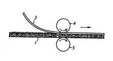
따라서, 다음 공정에서는, 도2에 나타나는 것과 같이, 니들펀칭가공에 의해 얻어진 띠형상 수지흡착재(부직포)(1)의 니들(2)이 돌출된 측(도2의 윗면)에 상기 수지흡착재(1)보다 폭이 좁은 기밀성이 높은 플라스틱필름(3)이 용착된다.Therefore, in the next step, as shown in Fig. 2, the resin adsorbent 1 is formed on the side (upper surface of Fig. 2) where the needle 2 of the strip-shaped resin adsorbent (nonwoven fabric) 1 obtained by needle punching is protruded. A narrow airtight plastic film (3) is welded.
여기에서, 상기 플라스틱필름(3)은 스틸렌에 대하여 내성이 높은 폴리우레탄, 나일론 또는 EVOH를 포함하는 3종 5층 또는 3종 10층 필름으로 구성되고, 이것을 수지흡착재(1) 윗면에 설치하여 수지흡착재(1)와 함께 상하의 가열롤러(4)와 가압롤러(5) 사이를 통과시킴으로써 도3에 나타나는 것과 같이 수지흡착재(1)의 윗면 폭방향 양단에 봉제대를 남기고 용착된다.Here, the
즉, 가열롤러(4)는 스팀에 의해서 소정 온도로 가열되어 있고, 도2의 화살표방향으로 회전하는 가열롤러(4)와 가압롤러(5) 사이에 상하로 포개진 플라스틱필름 (3)과 수지흡착재(1)를 도시된 화살표방향으로 통과시킴으로써 플라스틱필름(3)이 수지흡착재(1)의 윗면(니들펀칭가공에 있어서 니들(2)이 돌출된 측의 면)에 용착되며, 도3에 나타낸 것과 같이, 수지흡착재(1)의 윗면의 폭방향 양단부에는 플라스틱필름(3)이 용착되어 있지 않은 봉제대부분(1a)이 남겨진다. 또한, 본 실시의 형태에서는 플라스틱필름(3)이 수지흡착재(1)의 윗면에 용착되거나, 접착제에 의해서 접착되어도 좋다.That is, the heating roller 4 is heated to a predetermined temperature by steam, and the
그리고, 도3에 나타나는 것과 같이 수지흡착재(1)의 윗면에 플라스틱필름(3)이 용착되면, 이 플라스틱필름(3)이 용착된 수지흡착재(1)를 도4에 나타낸 것과 같이 플라스틱필름(3)이 외측이 되도록 하여 접어 그 폭방향 단부끼리를 포개고, 그 포갠 부분의 사이에 U자 형상으로 접은 보강리본테이프(6)를 끼워 이것을 용착 또는 접착에 의해서 임시로 붙인 다음, 포개진 부분을 보강리본테이프(6)와 함께 봉제사(7)를 사용하여 록바느질하여 접합한다. 또한, 봉제사(7)의 재질로서는 나일론, 폴리에스테르, 케블라 또는 세라믹이 사용되고, 보강리본테이프(6)는 수지흡착재(1)와 같은 재질로 구성되어 있다.As shown in FIG. 3, when the
상술한 바와 같이, 수지흡착재(1)의 포개진 부분이 록바느질에 의해서 접합되면, 그 접합부를 좌우로 잡아 당기면, 도5에 나타나는 것과 같이 접합부에서 단부끼리 맞대어지고, 그 맞댐부의 내측이 보강리본테이프(6)에 의해서 보강된다.As described above, when the overlapped portion of the resin absorbent material 1 is joined by lock stitching, when the joint portion is pulled to the left or right, the ends are joined to each other at the joint portion as shown in Fig. 5, and the inner side of the butt portion is reinforced ribbon. It is reinforced by the
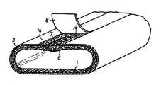
그 다음, 도5에 나타나는 것과 같이 관형상으로 성형된 수지흡착재(1)의 봉제부를 포함하는 접합부(봉제대부분(1a))의 외면에 봉제보호테이프(8)를 용착 또는 접착하고, 도6에 나타나는 것과 같이 봉제보호테이프(8)보다 폭이 넓은 밀봉리본테이프(9)를 봉제보호테이프(8)의 위에서 그 양측의 플라스틱필름(3)에 걸쳐 용착 또는 접착하여 봉제부를 기밀하게 가공한다. 또한, 봉제보호테이프(8)는 인장신장이 작은 부직포 또는 직포를 혼입한 부직포로 구성되고, 부직포는 폴리에스테르, 아크릴, 비닐론 등의 섬유로 구성되고, 필요에 따라 이것에 탄소나 케블라의 섬유를 혼입해도 좋다. 또한, 밀봉리본테이프(9)는 상기 플라스틱필름(3)과 동재질의 필름으로 구성되어 있다.Next, as shown in FIG. 5, the
그런데, 봉제보호테이프(8)는 이것을 구성하는 섬유를 버너등에 의해 녹여서 용착되거나, 혹은 폴리아미드계(나일론) 또는 이오노머등의 열접착제에 의해서 접착된다.By the way, the sewing
또한, 상기 밀봉리본테이프(9)는 도7 및 도8에 나타나는 방법에 의하여 열용착된다. 즉, 도7에 나타나는 것과 같이 밀봉리본테이프(9)를 봉제보호테이프(8) 위쪽에서 덮도록 하여 관상수지흡착재(1)의 봉제부에 씌우고, 그 폭방향 양단부를 봉제보호테이프(8) 양측의 플라스틱필름(3)에 임시로 붙인 다음, 진공펌프(10)를 구동하여 진공호스(11)를 통해 관형상수지흡착재(1)가 진공이 되도록 그 내부를 감압한다. 또한, 관형상수지흡착재(1)의 진공이 되는 상태를 도8에 나타낸다.In addition, the sealing
상술된 바와 같이, 관형상수지흡착재(1)가 진공이 되어 그 내부가 감압되면, 밀봉리본테이프(9)는 봉제보호테이프(8)와 플라스틱필름(3)에 밀착하고, 이 상태를 유지한 채로 관형상수지흡착재(1)를 히터(12)의 아래쪽에서 도7의 화살표 방향으로 소정의 속도로 이동시키면, 그 외주면에 임시로 붙여진 밀봉리본테이프(9)가 히터(12)에 의해서 가열되어 봉제보호테이프(8)와 플라스틱필름(3)에 용착되고, 이것에 의해서 관형상수지흡착재(1)의 봉제부가 기밀하게 가공된다.As described above, when the tubular resin adsorbent 1 is vacuumed and the inside thereof is depressurized, the sealing
여기에서, 밀봉리본테이프(9) 용착방법의 다른 형태를 도9 및 도10에 나타낸 다.Here, another form of the welding method of the sealing
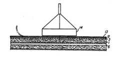
도9는 밀봉리본테이프(9) 용착방법의 다른 형태를 나타내는 측단면도, 도10은 동 사시도이고, 본 방법은, 밀봉리본테이프(9) 위에 이것보다도 융점이 높은 이형부재(13)를 포개고, 누름히터(14)에 의해서 이형부재(13)를 사이에 두고 밀봉리본테이프(9)를 누르면서 가열하여 상기 밀봉리본테이프(9)를 상기 봉제보호테이프(8)와 플라스틱필름(3)에 용착시키고, 냉각후에 이형부재(13)를 제거하는 것을 특징으로 한다. 또한, 이형부재(13)의 재질로는 종이, 플라스틱필름, 직포 등이 선정되고, 상기 이형부재(13)는 열전도성을 고려하여 박육(薄肉)재료로 구성되며, 그 폭치수는 밀봉리본테이프(9)와 동등 또는 그것보다 크게 설정되어 있다. 또한, 누름히터(14)는 유체압 또는 전동에 의해서 압압되고, 전기, 스팀 또는 버너에 의해서 가열된다.Fig. 9 is a side cross-sectional view showing another embodiment of the sealing
그래서, 본 방법에 의하면, 밀봉리본테이프(9)와 누름히터(14) 사이에 이형부재(13)가 끼워지기 때문에, 밀봉리본테이프(9)가 녹아서 누름히터(14)에 붙게 되지 않고, 누름히터(14)에 의해서 밀봉리본테이프(9)를 강한 힘으로 압압하여 이것을 충분히 가열할 수 있어, 확실한 밀봉작업을 실행할 수 있다.Therefore, according to this method, since the
다음에, 수지흡착재(1) 봉제부의 밀봉방법의 다른 형태를 도11 ∼ 도13에 각각 나타내고 있다.Next, the other form of the sealing method of the sewing part of the resin adsorption material 1 is shown in FIGS.
도11에 나타나는 방법은, 도11(a)에 나타나는 것과 같이 수지흡착재(1)의 봉제대부분(플라스틱필름(3)이 피복되어 있지 않은 부분)(1a)과 같은 폭 혹은 약간 폭이 좁은 봉제보호테이프(8)의 표면에 상기 봉제보호테이프(8)보다도 폭이 넓은 밀봉리본테이프(9)를 미리 용착 또는 접착하여, 도11(b)에 나타나는 것과 같이 봉제보호테이프(8)를 수지흡착재(1)의 봉제대부분(1a)에 위에서부터 끼워넣도록 하여 이것을 밀봉리본테이프(9)와 함께 봉제부에 씌우고, 밀봉리본테이프(9)의 봉제보호테이프(8)의 측방향으로부터 밀려나오는 양측부분을 플라스틱필름(3)에 용착 또는 접착함으로써 봉제부(접합부)를 기밀하게 밀봉하는 방법이다.The method shown in Fig. 11 is the same as the sewing portion of the resin adsorbent 1 (part not covered with the plastic film 3) 1a as shown in Fig. 11 (a). The sealing
또한, 도 12에 나타나는 방법은, 도12(a)에 나타나는 것과 같이 수지흡착재 (1)의 봉제대부분(1a)과 같은 폭 혹은 약간 폭이 좁은 봉제보호테이프(8)의 표면에 밀봉리본테이프(플라스틱필름(3))(9)와 같은 재질 같은 폭의 플라스틱리본테이프 (15)를 미리 용착 또는 접착하여, 이들을 도12(b)에 나타나는 것과 같이 수지흡착재(1)의 봉제대부분(1a)에 위에서부터 끼워넣고, 그 위에서부터 폭이 넓은 밀봉리본테이프(9)를 씌워 이것을 플라스틱리본테이프(15)와 플라스틱필름(3)에 용착 또는 접착함으로써 봉제부(접합부)를 기밀하게 밀봉하는 방법이다.In addition, the method shown in FIG. 12 uses a sealing ribbon tape (a sealing ribbon tape) on the surface of the sewing
또한, 도13에 나타나는 방법은, 도13(a)에 나타나는 것과 같이 수지흡착재 (1)의 봉제대부분(1a)보다 폭이 넓은 봉재보호테이프(8)의 표면에 상기 봉제보호테이프(8)보다 폭이 넓은 밀봉리본테이프(9)를 미리 용착 또는 접착하여, 이들을 도13(b)에 나타나는 것과 같이 수지흡착재(1)의 봉제대부분(1a)을 윗쪽에서 덮도록 씌워, 봉제보호테이프(8)의 봉제대부분(1a)으로부터 밀려나오는 양측부분과 밀봉리본테이프(9)의 봉제보호테이프(8)로부터 측방향으로 밀려나오는 양측부분을 플라스틱필름(3)에 용착 또는 접착함으로써 봉제부(접합부)를 기밀하게 밀봉하는 방법이다.In addition, the method shown in FIG. 13 has a width greater than that of the sewing
그래서 이상의 방법에 의해서 도6에 나타난 것과 같이 관형상수지흡착재(1)의 봉제접합부가 기밀하게 가공되면, 상기 관형상수지흡착재(1)에 임의의 방법에 의해서 미경화의 액상경화성수지를 함침시키면 원하는 관 라이닝재가 얻어지고, 이 관 라이닝재는 노후화된 관로의 라이닝재에 제공된다.Thus, when the sewing joint of the tubular resin adsorbent (1) is hermetically processed as shown in Fig. 6, the tubular resin adsorbent (1) is impregnated with an uncured liquid curable resin by any method. The desired pipe lining material is obtained, which is provided to the lining material of the aging pipeline.
또, 관형상수지흡착재(1)에 함침되는 경화성수지로는, 불포화 폴리에스테르수지, 에폭시수지 등의 열경화성수지가 일반적으로 사용되지만, 광경화성수지나 상온경화성수지 등을 사용해도 좋다.As the curable resin impregnated in the tubular resin adsorbent (1), thermosetting resins such as unsaturated polyester resins and epoxy resins are generally used, but photocurable resins, room temperature curable resins, and the like may be used.
이상에 있어, 본 발명에 관한 관 라이닝재의 제조방법에 있어서는, 관형상으로 가공된 수지흡착재(1)의 외주면에는 플라스틱플름(3)으로 피복되어 있지 않은 봉제대부분(1a)이 형성되고, 이 봉제대부분(1a)에 나타나는 봉제사(7)는 봉제보호테이프(8)로 덮어져 보호되며, 그 위에 폭이 넓은 밀봉리본테이프(9)가 씌워지고 상기 밀봉리본테이프(9)의 봉제보호테이프(8)의 측방향으로부터 밀려나오는 양측부분이 플라스틱필름(3)에 용착 또는 접착됨으로써 봉제부가 기밀하게 밀봉되기 때문에, 관 라이닝재에 핀홀이 발생하는 일이 없이, 간단한 작업으로 봉제부의 밀봉을 확실히 행할 수가 있다.As mentioned above, in the manufacturing method of the pipe lining material which concerns on this invention, the sewing base part 1a which is not coat | covered with the
또, 이상의 실시 형태에서는 관 라이닝재를 단층의 관형상수지흡착재로 구성하였으나, 관 라이닝재의 두께를 조정하는 경우에는 관형상수지흡착재를 다층구조로 해도 좋다.In addition, in the above embodiment, the tubular lining material is composed of a single layer tubular resin adsorbent, but in the case of adjusting the thickness of the tubular lining material, the tubular resin adsorbent may have a multilayer structure.
이상의 설명으로 분명하듯이, 본 발명에 의하면, 외표면이 기밀성이 높은 플라스틱필름으로 피복된 관형상수지흡착재에 경화성수지를 함침시켜 이루어지는 관 라이닝재의 제조방법에 있어서, 띠형상의 수지흡착재의 폭방향 양단에 봉제대를 남기고 표면에 상기 수지흡착재보다 폭이 좁은 플라스틱필름을 용착하고, 상기 수지흡착재를 상기 플라스틱필름이 외측이 되도록 하여 접어서 그 폭방향 단부끼리 포개고, 그 포갠 부분을 록바느질하여 수지흡착재를 관형상으로 가공한 다음, 상기 수지흡착재의 봉제부를 포함하는 상기 봉제대부분에 봉제보호테이프를 용착 또는 접착하여, 상기 봉제보호테이프보다 폭이 넓은 밀봉리본테이프를 봉제보호테이프의 위에서 용착 또는 접착하여 봉제부를 기밀하게 가공하도록 하였기 때문에, 핀홀의 발생을 초래하지 않고, 간단한 작업으로 봉제부의 밀봉을 확실히 행할 수 있게 된다는 효과가 얻어진다.As is clear from the above description, according to the present invention, in the method for producing a tubular lining material in which the outer surface is impregnated with a tubular resin adsorbent coated with a highly airtight plastic film, the width direction of the strip-shaped resin adsorbent Leave the sewing bars on both ends and weld the plastic film narrower than the resin adsorbent on the surface, and fold the resin adsorbent so that the plastic film is on the outside, and overlap the end portions in the width direction, and lock the folded portion to sew the resin adsorbent. After processing into a tubular shape, by welding or bonding a sewing protective tape to the sewing portion including the sewing portion of the resin adsorbent, by welding or bonding a sealing ribbon tape wider than the sewing protective tape on the sewing protective tape Since the sewing part is made to be airtight, pinholes are generated. If not, a simple operation is obtained an effect that surely possible to perform the sewing of the sealing portion with.
Claims (8)
Translated fromKoreanApplications Claiming Priority (2)
| Application Number | Priority Date | Filing Date | Title |
|---|---|---|---|
| JP98-272177 | 1998-09-25 | ||
| JP27217798AJP3790052B2 (en) | 1998-09-25 | 1998-09-25 | Manufacturing method of pipe lining material |
Publications (2)
| Publication Number | Publication Date |
|---|---|
| KR20000023131A KR20000023131A (en) | 2000-04-25 |
| KR100574270B1true KR100574270B1 (en) | 2006-04-27 |
Family
ID=17510162
Family Applications (1)
| Application Number | Title | Priority Date | Filing Date |
|---|---|---|---|
| KR19990039289AExpired - Fee RelatedKR100574270B1 (en) | 1998-09-25 | 1999-09-14 | Method of manufacturing a pipe liner bag |
Country Status (3)
| Country | Link |
|---|---|
| US (2) | US6296729B1 (en) |
| JP (1) | JP3790052B2 (en) |
| KR (1) | KR100574270B1 (en) |
Cited By (3)
| Publication number | Priority date | Publication date | Assignee | Title |
|---|---|---|---|---|
| KR102422914B1 (en) | 2022-02-11 | 2022-07-20 | (주)삼명이엔씨 | Lining pad with a guide string for maintenance of polygonal pipe, manufacturing method and construction method of the same |
| KR102422920B1 (en) | 2022-02-11 | 2022-07-20 | (주)삼명이엔씨 | Lining pad with a reinforcing member for maintenance of polygonal pipe and manufacturing method of the same |
| KR102422905B1 (en) | 2022-02-11 | 2022-07-20 | (주)삼명이엔씨 | Lining pad with bending portion for maintenance of polygonal pipe and manufacturing method of the same |
Families Citing this family (36)
| Publication number | Priority date | Publication date | Assignee | Title |
|---|---|---|---|---|
| US6364356B1 (en)* | 1999-09-24 | 2002-04-02 | Milliken & Company | Airbag cushion comprising sewn reinforcement seams |
| US20030029514A1 (en)* | 2001-08-10 | 2003-02-13 | Winzeler Michael D. | Flexible hose |
| US6932116B2 (en)* | 2002-03-14 | 2005-08-23 | Insituform (Netherlands) B.V. | Fiber reinforced composite liner for lining an existing conduit and method of manufacture |
| US6708729B1 (en)* | 2002-03-14 | 2004-03-23 | Instituform B.V. | Fiber reinforced composite liner for lining an existing conduit and method of manufacture |
| US6732763B2 (en)* | 2002-05-24 | 2004-05-11 | Lantor, Inc. | Stretch-resistant pipe liner |
| US6837273B2 (en) | 2002-06-19 | 2005-01-04 | Saint-Gobain Technical Fabrics Canada, Ltd. | Inversion liner and liner components for conduits |
| US7096890B2 (en) | 2002-06-19 | 2006-08-29 | Saint-Gobain Technical Fabrics Canada, Ltd. | Inversion liner and liner components for conduits |
| KR20040042759A (en)* | 2002-11-14 | 2004-05-20 | (주)월암케미칼 | a method of taping the joint of tube liner used for hardening and its device |
| JP4545399B2 (en)* | 2003-08-25 | 2010-09-15 | 旭テック環境ソリューション株式会社 | Rehabilitation material and manufacturing method thereof |
| US7857932B1 (en)* | 2003-11-07 | 2010-12-28 | Ina Acquisition Corp. | Cured in place liner with everted outer impermeable layer and method of manufacture |
| US7261788B1 (en)* | 2003-11-07 | 2007-08-28 | Insitaform (Netherlands) B.V. | Preparation of cured in place liner with integral inner impermeable layer |
| US20050281970A1 (en)* | 2004-06-16 | 2005-12-22 | Lamarca Louis J Ii | Lateral liner substrates |
| DE202005019995U1 (en)* | 2005-04-12 | 2006-04-13 | Vereinigte Filzfabriken Ag | Hose for rehabilitation of pipelines |
| US20070184226A1 (en)* | 2006-02-03 | 2007-08-09 | Winzeler Michael D | Flexible hose |
| US7891381B2 (en)* | 2007-05-10 | 2011-02-22 | Novoc Performance Resins | Pipe and tube rehabilitation liners and corresponding resins |
| US20080277012A1 (en)* | 2007-05-10 | 2008-11-13 | Anders Richard M | Reinforcing Liner |
| WO2010104941A2 (en)* | 2009-03-11 | 2010-09-16 | Deepflex Inc. | Method and apparatus to repair flexible fiber-reinforced pipe |
| KR101033168B1 (en)* | 2009-07-31 | 2011-05-11 | 호용종합건설주식회사 | Folding device of pipe lining bag |
| US9222611B2 (en)* | 2011-03-30 | 2015-12-29 | Dartex Coatings, Inc. | Flexible barrier composite fabrics via an adhered film process |
| DE102011103001B4 (en)* | 2011-05-24 | 2023-03-16 | Brandenburger Liner Gmbh & Co. Kg | Lining tube for the rehabilitation of defective sewers |
| US8850775B2 (en)* | 2012-05-04 | 2014-10-07 | Garland Industries, Inc. | Non-welded coping caps and transitions |
| DE102013014796A1 (en)* | 2013-09-09 | 2015-03-12 | Brandenburger Patentverwertung GbR (vertretungsberechtigter Gesellschafter: Wilhelm Leo Betz, 76887 Bad Bergzabern) | Lining hose with an outer film tube overlapped by adhesive tape for lining pipelines and method of making same |
| FI128138B (en)* | 2014-04-30 | 2019-10-31 | Tomas Henrik Mikael Forsman | remediation Sock |
| DE102015105668C5 (en)* | 2015-04-14 | 2020-07-09 | Cuylits Holding GmbH | Composite hose for repairing leaky fluid lines, method for producing such a composite hose and method for repairing leaky fluid lines with a composite hose |
| CN107297908B (en)* | 2017-07-03 | 2023-10-27 | 广州樱泰汽车饰件有限公司 | Automatic sewing jig |
| CN108115944B (en)* | 2017-12-26 | 2021-03-09 | 天津工业大学 | Method for connecting composite material pipe and metal pipe |
| US11173634B2 (en) | 2018-02-01 | 2021-11-16 | Ina Acquisition Corp | Electromagnetic radiation curable pipe liner and method of making and installing the same |
| JP7021421B2 (en)* | 2018-02-05 | 2022-02-17 | タキロンシーアイシビル株式会社 | Tube lining material and its manufacturing method |
| US10704728B2 (en) | 2018-03-20 | 2020-07-07 | Ina Acquisition Corp. | Pipe liner and method of making same |
| US20210222812A1 (en)* | 2018-08-28 | 2021-07-22 | Mitsubishi Electric Corporation | Pipe with sound absorber, refrigeration cycle apparatus, and method for mounting sound absorber |
| GB2580957B (en)* | 2019-01-31 | 2021-11-03 | W E Rawson Ltd | Improvements relating to pipe liners |
| CN110094595B (en)* | 2019-04-28 | 2020-09-04 | 洛阳恒基石化科技有限公司 | Automatic leakage-repairing hose |
| KR102186950B1 (en) | 2020-06-24 | 2020-12-04 | 리니어(주) | Double-sided Fusion Reinforcement Tube for Non-excavation Sewer Repair Work |
| DE102021006141A1 (en)* | 2021-12-13 | 2023-06-15 | Brandenburger Liner Gmbh & Co. Kg | Lining hose for rehabilitating defective manholes including berms and channels and method for producing such and method for lining a defective manhole |
| TW202325174A (en) | 2021-12-21 | 2023-07-01 | 美商百美貼有限公司 | Waterproof seams and methods of making the same |
| JP7536930B1 (en) | 2023-03-07 | 2024-08-20 | 三菱重工業株式会社 | Joint member and method for manufacturing the same |
Citations (6)
| Publication number | Priority date | Publication date | Assignee | Title |
|---|---|---|---|---|
| JPH0939095A (en)* | 1995-07-31 | 1997-02-10 | Shonan Gosei Jushi Seisakusho:Kk | Pipe lining material and manufacture thereof |
| US5698056A (en)* | 1995-02-13 | 1997-12-16 | Yokoshima & Company | Method for manufacturing a tubular liner bag |
| US5780123A (en)* | 1995-03-23 | 1998-07-14 | Yokoshima & Company | Tubular liner and a method for connecting ends of liner tubes |
| KR19980041875A (en)* | 1996-11-21 | 1998-08-17 | 카미야마타카오 | Manufacturing method of pipe lining material |
| KR19980041840A (en)* | 1996-11-21 | 1998-08-17 | 카미야마타카오 | Pipe lining material and manufacturing method |
| JPH10235736A (en)* | 1997-02-28 | 1998-09-08 | Shonan Gosei Jushi Seisakusho:Kk | Pipe lining material and method of manufacturing the same |
Family Cites Families (6)
| Publication number | Priority date | Publication date | Assignee | Title |
|---|---|---|---|---|
| EP0009402A1 (en)* | 1978-09-22 | 1980-04-02 | Insituform International Inc. | A method of forming laminated hoses and laminated hoses obtained |
| JPH0745182B2 (en) | 1990-06-29 | 1995-05-17 | 株式会社ゲット | Method for manufacturing pipe lining material |
| JP2554411B2 (en) | 1991-05-31 | 1996-11-13 | 株式会社ゲット | Branch pipe lining material and manufacturing method thereof |
| US5765597A (en) | 1994-08-19 | 1998-06-16 | Kiest, Jr.; Larry W. | Apparatus for repairing a pipeline and method for using same |
| WO1997017187A1 (en)* | 1995-11-09 | 1997-05-15 | Ashimori Industry Co., Ltd. | Conduit lining material and method of manufacturing the same |
| JP2000127242A (en) | 1998-10-26 | 2000-05-09 | Shonan Gosei Jushi Seisakusho:Kk | Manufacturing method of pipe lining material |
- 1998
- 1998-09-25JPJP27217798Apatent/JP3790052B2/ennot_activeExpired - Fee Related
- 1999
- 1999-09-14KRKR19990039289Apatent/KR100574270B1/ennot_activeExpired - Fee Related
- 1999-09-17USUS09/399,205patent/US6296729B1/ennot_activeExpired - Fee Related
- 2001
- 2001-08-24USUS09/939,477patent/US6562426B1/ennot_activeExpired - Fee Related
Patent Citations (6)
| Publication number | Priority date | Publication date | Assignee | Title |
|---|---|---|---|---|
| US5698056A (en)* | 1995-02-13 | 1997-12-16 | Yokoshima & Company | Method for manufacturing a tubular liner bag |
| US5780123A (en)* | 1995-03-23 | 1998-07-14 | Yokoshima & Company | Tubular liner and a method for connecting ends of liner tubes |
| JPH0939095A (en)* | 1995-07-31 | 1997-02-10 | Shonan Gosei Jushi Seisakusho:Kk | Pipe lining material and manufacture thereof |
| KR19980041875A (en)* | 1996-11-21 | 1998-08-17 | 카미야마타카오 | Manufacturing method of pipe lining material |
| KR19980041840A (en)* | 1996-11-21 | 1998-08-17 | 카미야마타카오 | Pipe lining material and manufacturing method |
| JPH10235736A (en)* | 1997-02-28 | 1998-09-08 | Shonan Gosei Jushi Seisakusho:Kk | Pipe lining material and method of manufacturing the same |
Cited By (3)
| Publication number | Priority date | Publication date | Assignee | Title |
|---|---|---|---|---|
| KR102422914B1 (en) | 2022-02-11 | 2022-07-20 | (주)삼명이엔씨 | Lining pad with a guide string for maintenance of polygonal pipe, manufacturing method and construction method of the same |
| KR102422920B1 (en) | 2022-02-11 | 2022-07-20 | (주)삼명이엔씨 | Lining pad with a reinforcing member for maintenance of polygonal pipe and manufacturing method of the same |
| KR102422905B1 (en) | 2022-02-11 | 2022-07-20 | (주)삼명이엔씨 | Lining pad with bending portion for maintenance of polygonal pipe and manufacturing method of the same |
Also Published As
| Publication number | Publication date |
|---|---|
| KR20000023131A (en) | 2000-04-25 |
| JP3790052B2 (en) | 2006-06-28 |
| JP2000094549A (en) | 2000-04-04 |
| US6562426B1 (en) | 2003-05-13 |
| US6296729B1 (en) | 2001-10-02 |
Similar Documents
| Publication | Publication Date | Title |
|---|---|---|
| KR100574270B1 (en) | Method of manufacturing a pipe liner bag | |
| KR20000029291A (en) | Method of manufacturing a pipe liner bag | |
| EP2397312B1 (en) | Method for bonding cylindrical members | |
| EP0548417B1 (en) | Method for manufacturing a pipe liner. | |
| US4446181A (en) | Manufacture of tubular laminates | |
| EP3543582B1 (en) | Pipe liner and method of making and installing the same | |
| JP2014015049A (en) | Stitchless seam system for jointing laminate | |
| KR19980071864A (en) | Pipe lining material and manufacturing method | |
| JPH0745182B2 (en) | Method for manufacturing pipe lining material | |
| WO2012082949A1 (en) | Curable pressure pipe liner | |
| JP2019135403A (en) | Pipe lining material and manufacturing method thereof | |
| JP2974130B2 (en) | Manufacturing method of pipe lining material | |
| KR102457755B1 (en) | Non-excavation repair/reinforcement tube applied with coated composite fiber and its manufacturing method | |
| JP6954798B2 (en) | Laminated body for pipe rehabilitation and member for pipe rehabilitation | |
| JPH11235758A (en) | Manufacturing method of pipe lining material and pipe lining method | |
| KR19980079866A (en) | Tube lining | |
| EP3918244B1 (en) | Pipe liner | |
| KR20230059468A (en) | Liner tube and manufacturing method thereof | |
| JP4840708B2 (en) | Pipe lining material and manufacturing method thereof | |
| JP3072977B2 (en) | Pipe lining material and method of manufacturing the same | |
| JP3851035B2 (en) | Pipe lining material | |
| JP2005319625A (en) | Manufacturing method of laminated base material for pipe lining and pipe lining material manufacturing method | |
| JP2001198980A (en) | Pipe lining material | |
| JP2678151B2 (en) | Pipe lining material and method of manufacturing the same | |
| CA2221657A1 (en) | Pipe liner bag and manufacturing method therefor |
Legal Events
| Date | Code | Title | Description |
|---|---|---|---|
| PA0109 | Patent application | St.27 status event code:A-0-1-A10-A12-nap-PA0109 | |
| PG1501 | Laying open of application | St.27 status event code:A-1-1-Q10-Q12-nap-PG1501 | |
| A201 | Request for examination | ||
| P11-X000 | Amendment of application requested | St.27 status event code:A-2-2-P10-P11-nap-X000 | |
| P13-X000 | Application amended | St.27 status event code:A-2-2-P10-P13-nap-X000 | |
| PA0201 | Request for examination | St.27 status event code:A-1-2-D10-D11-exm-PA0201 | |
| D13-X000 | Search requested | St.27 status event code:A-1-2-D10-D13-srh-X000 | |
| D14-X000 | Search report completed | St.27 status event code:A-1-2-D10-D14-srh-X000 | |
| E701 | Decision to grant or registration of patent right | ||
| PE0701 | Decision of registration | St.27 status event code:A-1-2-D10-D22-exm-PE0701 | |
| GRNT | Written decision to grant | ||
| PR0701 | Registration of establishment | St.27 status event code:A-2-4-F10-F11-exm-PR0701 | |
| PR1002 | Payment of registration fee | St.27 status event code:A-2-2-U10-U11-oth-PR1002 Fee payment year number:1 | |
| PG1601 | Publication of registration | St.27 status event code:A-4-4-Q10-Q13-nap-PG1601 | |
| LAPS | Lapse due to unpaid annual fee | ||
| PC1903 | Unpaid annual fee | St.27 status event code:A-4-4-U10-U13-oth-PC1903 Not in force date:20090421 Payment event data comment text:Termination Category : DEFAULT_OF_REGISTRATION_FEE | |
| PC1903 | Unpaid annual fee | St.27 status event code:N-4-6-H10-H13-oth-PC1903 Ip right cessation event data comment text:Termination Category : DEFAULT_OF_REGISTRATION_FEE Not in force date:20090421 |