KR100570634B1 - Electromagnetic shielding material manufactured by carbon nanotube and metal powder hybrid composite - Google Patents
Electromagnetic shielding material manufactured by carbon nanotube and metal powder hybrid compositeDownload PDFInfo
- Publication number
- KR100570634B1 KR100570634B1KR1020030072074AKR20030072074AKR100570634B1KR 100570634 B1KR100570634 B1KR 100570634B1KR 1020030072074 AKR1020030072074 AKR 1020030072074AKR 20030072074 AKR20030072074 AKR 20030072074AKR 100570634 B1KR100570634 B1KR 100570634B1
- Authority
- KR
- South Korea
- Prior art keywords
- carbon nanotubes
- metal powder
- volume ratio
- shielding material
- electromagnetic shielding
- Prior art date
- Legal status (The legal status is an assumption and is not a legal conclusion. Google has not performed a legal analysis and makes no representation as to the accuracy of the status listed.)
- Expired - Lifetime
Links
Images

Classifications
- H—ELECTRICITY
- H05—ELECTRIC TECHNIQUES NOT OTHERWISE PROVIDED FOR
- H05K—PRINTED CIRCUITS; CASINGS OR CONSTRUCTIONAL DETAILS OF ELECTRIC APPARATUS; MANUFACTURE OF ASSEMBLAGES OF ELECTRICAL COMPONENTS
- H05K9/00—Screening of apparatus or components against electric or magnetic fields
- H05K9/0073—Shielding materials
- H05K9/0081—Electromagnetic shielding materials, e.g. EMI, RFI shielding
- H05K9/0083—Electromagnetic shielding materials, e.g. EMI, RFI shielding comprising electro-conductive non-fibrous particles embedded in an electrically insulating supporting structure, e.g. powder, flakes, whiskers
- B—PERFORMING OPERATIONS; TRANSPORTING
- B82—NANOTECHNOLOGY
- B82Y—SPECIFIC USES OR APPLICATIONS OF NANOSTRUCTURES; MEASUREMENT OR ANALYSIS OF NANOSTRUCTURES; MANUFACTURE OR TREATMENT OF NANOSTRUCTURES
- B82Y10/00—Nanotechnology for information processing, storage or transmission, e.g. quantum computing or single electron logic
- B—PERFORMING OPERATIONS; TRANSPORTING
- B82—NANOTECHNOLOGY
- B82Y—SPECIFIC USES OR APPLICATIONS OF NANOSTRUCTURES; MEASUREMENT OR ANALYSIS OF NANOSTRUCTURES; MANUFACTURE OR TREATMENT OF NANOSTRUCTURES
- B82Y30/00—Nanotechnology for materials or surface science, e.g. nanocomposites
- C—CHEMISTRY; METALLURGY
- C08—ORGANIC MACROMOLECULAR COMPOUNDS; THEIR PREPARATION OR CHEMICAL WORKING-UP; COMPOSITIONS BASED THEREON
- C08K—Use of inorganic or non-macromolecular organic substances as compounding ingredients
- C08K3/00—Use of inorganic substances as compounding ingredients
- C08K3/02—Elements
- C08K3/08—Metals
- C—CHEMISTRY; METALLURGY
- C08—ORGANIC MACROMOLECULAR COMPOUNDS; THEIR PREPARATION OR CHEMICAL WORKING-UP; COMPOSITIONS BASED THEREON
- C08K—Use of inorganic or non-macromolecular organic substances as compounding ingredients
- C08K7/00—Use of ingredients characterised by shape
- C08K7/22—Expanded, porous or hollow particles
- C08K7/24—Expanded, porous or hollow particles inorganic
- H—ELECTRICITY
- H01—ELECTRIC ELEMENTS
- H01B—CABLES; CONDUCTORS; INSULATORS; SELECTION OF MATERIALS FOR THEIR CONDUCTIVE, INSULATING OR DIELECTRIC PROPERTIES
- H01B1/00—Conductors or conductive bodies characterised by the conductive materials; Selection of materials as conductors
- H01B1/20—Conductive material dispersed in non-conductive organic material
- H01B1/22—Conductive material dispersed in non-conductive organic material the conductive material comprising metals or alloys
- H—ELECTRICITY
- H01—ELECTRIC ELEMENTS
- H01B—CABLES; CONDUCTORS; INSULATORS; SELECTION OF MATERIALS FOR THEIR CONDUCTIVE, INSULATING OR DIELECTRIC PROPERTIES
- H01B1/00—Conductors or conductive bodies characterised by the conductive materials; Selection of materials as conductors
- H01B1/20—Conductive material dispersed in non-conductive organic material
- H01B1/24—Conductive material dispersed in non-conductive organic material the conductive material comprising carbon-silicon compounds, carbon or silicon
- C—CHEMISTRY; METALLURGY
- C08—ORGANIC MACROMOLECULAR COMPOUNDS; THEIR PREPARATION OR CHEMICAL WORKING-UP; COMPOSITIONS BASED THEREON
- C08K—Use of inorganic or non-macromolecular organic substances as compounding ingredients
- C08K2201/00—Specific properties of additives
- C08K2201/011—Nanostructured additives
- H—ELECTRICITY
- H01—ELECTRIC ELEMENTS
- H01F—MAGNETS; INDUCTANCES; TRANSFORMERS; SELECTION OF MATERIALS FOR THEIR MAGNETIC PROPERTIES
- H01F1/00—Magnets or magnetic bodies characterised by the magnetic materials therefor; Selection of materials for their magnetic properties
- H01F1/01—Magnets or magnetic bodies characterised by the magnetic materials therefor; Selection of materials for their magnetic properties of inorganic materials
- H01F1/03—Magnets or magnetic bodies characterised by the magnetic materials therefor; Selection of materials for their magnetic properties of inorganic materials characterised by their coercivity
- H01F1/12—Magnets or magnetic bodies characterised by the magnetic materials therefor; Selection of materials for their magnetic properties of inorganic materials characterised by their coercivity of soft-magnetic materials
- H01F1/14—Magnets or magnetic bodies characterised by the magnetic materials therefor; Selection of materials for their magnetic properties of inorganic materials characterised by their coercivity of soft-magnetic materials metals or alloys
- H01F1/20—Magnets or magnetic bodies characterised by the magnetic materials therefor; Selection of materials for their magnetic properties of inorganic materials characterised by their coercivity of soft-magnetic materials metals or alloys in the form of particles, e.g. powder
Landscapes
- Chemical & Material Sciences (AREA)
- Engineering & Computer Science (AREA)
- Physics & Mathematics (AREA)
- Nanotechnology (AREA)
- Dispersion Chemistry (AREA)
- Spectroscopy & Molecular Physics (AREA)
- Medicinal Chemistry (AREA)
- Polymers & Plastics (AREA)
- Organic Chemistry (AREA)
- Crystallography & Structural Chemistry (AREA)
- Chemical Kinetics & Catalysis (AREA)
- Health & Medical Sciences (AREA)
- Theoretical Computer Science (AREA)
- Mathematical Physics (AREA)
- Condensed Matter Physics & Semiconductors (AREA)
- Composite Materials (AREA)
- General Physics & Mathematics (AREA)
- Materials Engineering (AREA)
- Electromagnetism (AREA)
- Microelectronics & Electronic Packaging (AREA)
- Compositions Of Macromolecular Compounds (AREA)
- Shielding Devices Or Components To Electric Or Magnetic Fields (AREA)
Abstract
Translated fromKoreanDescription
Translated fromKorean도 1은 본 발명의 실시예에 따른 전자파 차폐재의 조성물을 도시한 개념도,1 is a conceptual diagram showing a composition of an electromagnetic shielding material according to an embodiment of the present invention,
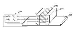
도 2는 표면비저항 측정 장치(MIL-G-835288)를 도시한 도면.2 is a diagram showing a surface specific resistance measuring apparatus (MIL-G-835288).
* 도면의 주요 부분에 대한 부호의 설명* Explanation of symbols for the main parts of the drawings
100 : 전자파 차페재 101 : 탄소나노튜브100: electromagnetic shielding material 101: carbon nanotubes
102 : 금속분말 103 : 고분자수지102: metal powder 103: polymer resin
본 발명은 전자파 차폐재에 관한 것으로, 특히 전자파 차폐율이 우수한 전자파 차폐재에 관한 것이다.The present invention relates to an electromagnetic wave shielding material, and more particularly, to an electromagnetic wave shielding material having excellent electromagnetic shielding rate.
전자기파의 유해성은 정보통신 기술의 발달 및 전자, 통신기기의 대량 보급과 더불어 날로 심각해지고 있는 것은 주지의 사실이며, 불요 전자파 발생에 따른 전파통신장치와 기기 상호간의 오동작 등은 전자기기 자체의 안전과 사회 또는 인간의 안전에 심각한 위험을 초래하는 것으로 여겨지고 있다. 때문에 선진 각 국에서는 국제 규격인 국제전기기술협의회(IEC)의 국제무선장해특별위원회(CISPR) 및 전자기적합성의 규격에 따라 전자파 장해 및 내성을 규제하고 있다.It is well known that the harmfulness of electromagnetic waves is increasing with the development of information and communication technology and the mass distribution of electronic and communication devices. It is believed to pose a serious danger to social or human safety. Therefore, developed countries regulate electromagnetic interference and immunity according to the International Radio Interference Special Committee (CISPR) of the International Electrotechnical Commission (IEC), which is an international standard, and the standards of electromagnetic compatibility.
따라서, 전기전자 제품의 원활한 판매를 위해서는 각 국에서 규정하고 있는 전자기적합성(Electromagnetic Compatibility; EMC) 기준을 만족시켜야 하며, 이러한 장해현상의 차단을 위해서 주로 전자파 차폐재료가 사용되어지고 있다.Therefore, in order to smoothly sell electrical and electronic products, the electromagnetic compatibility (EMC) standard specified in each country must be satisfied, and electromagnetic shielding materials are mainly used to block such obstacles.
전자파 차폐재는 실리콘 고무, 폴리우레탄, 폴리카보네이트, 에폭시 수지 등의 고분자에 전기전도성이 우수한 금속분말, 또는 탄소섬유 등을 30 체적% 이상 분산시킴으로써 얻는 것이 일반적인 방법이다. 이때 금속분말로서 은분 또는 은을 코팅한 구리(Ag-coated Cu) 등이 가장 전기전도 특성이 우수한 것으로 알려져 있으며, 이러한 은분 등을 체적비 30% 정도의 함량으로 고분자에 분산시켰을 경우에는 0.01Ω-cm 이하의 체적저항을 얻을 수 있고 약 50dB 정도의 차폐효과를 나타낼 수 있다.The electromagnetic wave shielding material is generally obtained by dispersing 30 vol% or more of a metal powder or carbon fiber having excellent electrical conductivity in a polymer such as silicone rubber, polyurethane, polycarbonate, and epoxy resin. At this time, silver powder or silver-coated copper is known to have the highest electrical conductivity. As the silver powder is dispersed in the polymer at a volume ratio of about 30%, 0.01 Ω-cm The following volume resistance can be obtained and a shielding effect of about 50 dB can be obtained.
최근에 더욱 엄격해지고 있는 전자파 차폐 장해 규격을 만족하기 위해서는 더욱 낮은 체적저항과 높은 차폐효과가 요구되고 있으며, 이를 위해서 더욱 많은 은분 등의 금속분말을 고분자에 분산시켜야 한다.In order to satisfy the more stringent electromagnetic wave shielding standards, a lower volume resistance and a higher shielding effect are required. For this purpose, more metal powder such as silver powder must be dispersed in the polymer.
그러나, 많은 금속분말 등을 고분자에 분산시켰을 경우, 전기전도도의 향상으로부터 전자파 차폐 효과를 높일 수는 있으나, 충격강도를 비롯한 기계적 물성의 저하를 초래하여 차폐재로서의 응용에 많은 제한이 따르게 된다.However, when a large amount of metal powder or the like is dispersed in a polymer, it is possible to increase the electromagnetic shielding effect from the improvement of the electrical conductivity, but it causes a decrease in mechanical properties including impact strength, which leads to many limitations in application as a shielding material.
한편, 전자파 차폐재로서 탄소나노튜브가 제안되었는데, 이이지마에 의해 탄소나노튜브가 최초로 발견된 후로[S. Iijima, Nature Vol. 354, P.56 (1991년)] 최근에는 그에 대한 많은 연구가 진행되고 있다. 탄소나노튜브는 기존의 재료에서는 찾아볼 수 없는 약 1.0∼1.8TPa의 높은 탄성률뿐만 아니라, 진공상태에서 2800℃의 온도에서도 견딜 수 있는 내열특성, 다이아몬드의 2배에 가까운 열전도도 및 구리와 비교하여 1000배 가량 높은 전류 이송 능력 등의 잠재적 물성으로 인하여 나노 스케일의 전기소자, 전자 소자, 나노센서, 광전자소자 및 고기능 복합재 등 모든 광학분야에서의 응용 가능성이 매우 높은 것으로 평가되고 있다.On the other hand, carbon nanotubes have been proposed as electromagnetic shielding materials, since carbon nanotubes were first discovered by Iijima [S. Iijima, Nature Vol. 354, P. 56 (1991)] A great deal of research has recently been conducted. Carbon nanotubes have high elastic modulus of about 1.0 ~ 1.8TPa, which is not found in conventional materials, as well as heat resistance that can withstand temperatures up to 2800 ℃ in vacuum, thermal conductivity close to twice that of diamond, and copper. Due to the potential physical properties such as 1000 times higher current carrying capacity, it is considered to be very applicable in all optical fields such as nano scale electric devices, electronic devices, nano sensors, optoelectronic devices and high-performance composites.
이러한 탄소나노튜브를 사용할 경우 고분자 매트릭스의 종류에 따라 다소 차이는 있으나 체적비 0.04% 이상만을 분산시켜도 전도 네트워크가 형성되어 반도체에 가까운 낮은 체적 저항을 얻을 수 있다.In the case of using such carbon nanotubes, there is a slight difference depending on the type of the polymer matrix, but even if only the volume ratio of 0.04% or more is dispersed, a conductive network can be formed to obtain a low volume resistance close to the semiconductor.
그러나, 탄소나노튜브만으로는 그 함량이 아무리 많다고 하더라도 최저 10Ω-cm 정도의 높은 체적전기저항을 나타내어 전자파 차폐 효과를 얻지 못하며, 탄소나노튜브를 고분자에 분산시킬 경우, 아주 적은 함량이라도 그 분산이 매우 어렵기 때문에 전자파 차폐재와 같은 복합재료로의 응용에 제약이 따르고 있다.However, no matter how much carbon nanotubes alone, they exhibit high volumetric electrical resistance of at least 10 Ω-cm and thus do not obtain electromagnetic shielding effects.If the carbon nanotubes are dispersed in a polymer, their dispersion is very difficult. Therefore, there is a restriction on the application to composite materials such as electromagnetic shielding material.
본 발명은 상기한 종래 기술의 문제점을 해결하기 위해 제안된 것으로, 낮은 체적저항을 달성하고 충격강도를 비롯한 물리적 기계적 특성을 향상시켜 각종 전자기기에서 신뢰성이 우수한 전자파 차폐재를 제공하는데 그 목적이 있다.The present invention has been proposed to solve the above problems of the prior art, and has an object of providing an electromagnetic shielding material having excellent reliability in various electronic devices by achieving low volume resistance and improving physical and mechanical properties including impact strength.
상기 목적을 달성하기 위한 본 발명의 전자파 차폐재는 전도성 충전재로서 탄소나노튜브와 금속분말을 포함하고, 고분자 수지를 매트릭스로 하되, 상기 탄소나노튜브의 체적비 함량은 0.2%∼10% 범위이고, 상기 금속분말의 체적비 함량은 8.3%∼30%이며, 상기 탄소나노튜브와 상기 금속분말의 혼합 체적비 함량이 조성물 전체에 대해 8.5%∼40%이 되도록 구성되며, 상기 탄소나노튜브는 단일벽 탄소나노튜브 또는 다중벽탄소나노튜브이며, 상기 단일벽 탄소나노튜브 또는 다중벽탄소나노튜브는 푸리에변환 적외선 분광법으로 분석된 표면분석 결과, 1300cm-1과 1100cm-1 사이의 페닐-카보닐 C-C 스트레치 결합 특성 피크가 존재하는 탄소나노튜브, 1300cm-1과 1100cm-1 사이의 페닐-카보닐 C-C 스트레치 결합, 1570cm-1과 1430cm-1 사이의 카보닉 C-C 스트레치 결합 및 1650cm-1 부근의 카르복실릭 그룹의 C=O 스티레칭 바이브레이션 특성 피크가 동시에 존재하는 탄소나노튜브, 1300cm-1과 1100cm-1 사이의 페닐-카보닐 C-C 스트레치 결합, 1650cm-1 부근의 카르복실릭 그룹의 C=O 스티레칭 바이브레이션 및 3550cm-1 에서의 -OH 결합특성 피크가 동시에 존재하는 탄소나노튜브, 1250cm-1 부근의 C-F 결합 특성 피크가 존재하는 탄소나노튜브 중 어느 하나를 사용하거나, 또는 상기 탄소나노튜브 중에서 적어도 두 종류가 혼합된 탄소나노튜브를 사용하는 것을 특징으로 한다.Electromagnetic shielding material of the present invention for achieving the above object comprises a carbon nanotube and a metal powder as a conductive filler, the polymer resin as a matrix, the volume ratio of the carbon nanotube ranges from 0.2% to 10%, the metal The volume ratio of the powder is 8.3% to 30%, and the mixed volume ratio of the carbon nanotubes and the metal powder is configured to be 8.5% to 40% with respect to the whole composition, and the carbon nanotubes are single-walled carbon nanotubes or and a multi-walled carbon nanotube, the single-wall carbon nanotubes or multi-wall carbon nanotubes phenyl between the surface analysis results of analysis by Fourier transform infrared spectroscopy, 1300cm-1 and 1100cm-1 - carbonyl stretch CC bond peak is characteristic existing carbon nanotube, phenyl between 1300cm-1 and 1100cm-1 - carbonyl stretch CC bond, 1570cm-1 and 1430cm-1 carbonyl nick between the CC bond stretch and 1650cm- Between thefirst vicinity of the carboxylic group of the C = O styryl reching vibration characteristic peak is present at the same time carbon nanotubes, 1300cm-1 and 1100cm-1 of phenyl-carbonyl stretch CC bond, a carboxylic group in the vicinity of 1650cm-1 Using either C = O stitching vibration and carbon nanotubes having a -OH binding characteristic peak at 3550 cm-1 at the same time, or a carbon nanotube having a CF binding characteristic peak near 1250 cm-1 , or the At least two kinds of carbon nanotubes are characterized by using carbon nanotubes mixed.
이하, 본 발명이 속하는 기술분야에서 통상의 지식을 가진 자가 본 발명의 기술적 사상을 용이하게 실시할 수 있을 정도로 상세히 설명하기 위하여, 본 발명의 가장 바람직한 실시예를 첨부 도면을 참조하여 설명하기로 한다.Hereinafter, the most preferred embodiments of the present invention will be described in detail with reference to the accompanying drawings so that those skilled in the art may easily implement the technical idea of the present invention. .
본 발명에서 제안하는 전자파 차폐재는 매우 높은 비표면적을 갖는 탄소나노튜브와 금속분말(은분 또는 은 코팅 구리)을 동시에 고분자 수지에 분산시킨 것으로, 높은 전기전도도와 우수한 기계적 물성을 갖는다.The electromagnetic wave shielding material proposed in the present invention is a carbon nanotube having a very high specific surface area and a metal powder (silver powder or silver coated copper) simultaneously dispersed in a polymer resin, and has high electrical conductivity and excellent mechanical properties.
즉, 본 발명은 전자파 차폐재를 구성하는 조성물로, 조성물내 체적비 0.2% 이상의 탄소나노튜브와 체적비 7.0% 이상의 은이 코팅된 구리 분말 등의 금속분말을 혼성하여 동시에 고분자 수지에 효율적으로 분산시키므로써, 최소 30dB 이상의 전자파 차폐효과를 얻을 수 있으며, 또한 낮은 전도성 충전재 함량으로부터 고분자 매트릭스의 높은 충격효과를 살려 응용의 확장과 신뢰성을 확보할 수 있다.That is, the present invention is a composition constituting the electromagnetic wave shielding material, by mixing a metal powder, such as carbon nanotubes with a volume ratio of 0.2% or more and copper powder coated with silver of a volume ratio of 7.0% or more, and simultaneously disperse efficiently in the polymer resin, Electromagnetic shielding effect of more than 30dB can be obtained, and the expansion and reliability of the application can be secured by utilizing the high impact effect of the polymer matrix from the low conductive filler content.
이처럼 본 발명의 전자파 차폐재는 고분자 매트릭스, 탄소나노튜브 및 금속분말을 필수성분으로 하고, 탄소나노튜브를 조성물 전체에 대해 체적비 0.2% 이상 으로 함유하고, 금속분말을 체적비 7.0% 이상으로 포함하며 탄소나노튜브와 금속분 말의 함량이 조성물 전체에 대해 체적비 7.2% 이상이 되도록 구성된다.As such, the electromagnetic wave shielding material of the present invention contains a polymer matrix, carbon nanotubes, and metal powder as essential components, contains carbon nanotubes in a volume ratio of 0.2% or more with respect to the entire composition, and includes metal powders in a volume ratio of 7.0% or more, and includes carbon nanoparticles. The content of the tube and metal powder is configured to be at least 7.2% by volume of the total composition.
이하, 본 발명의 실시예를 자세히 설명하면 다음과 같다.Hereinafter, an embodiment of the present invention will be described in detail.
도 1은 본 발명의 실시예에 따른 전자파 차폐재의 조성물을 도시한 개념도이다.1 is a conceptual diagram showing a composition of an electromagnetic shielding material according to an embodiment of the present invention.
도 1에 도시된 바와 같이, 전자파 차폐재(100)는 탄소나노튜브(101)와 금속분말(102)을 동시에 포함하고, 고분자 수지(103)를 매트릭스로 하는 조성물이다.As shown in FIG. 1, the
여기서, 탄소나노튜브(101)의 전체 조성물에 대한 체적비 함량은 0.2%∼10% 범위이고, 금속분말(102)의 전체 조성물에 대한 체적비 함량은 7.0%∼30%이며, 탄소나노튜브(101)와 금속분말(102)의 혼합 체적비 함량이 전체 조성물에 대해 7.2%∼40%이 되도록 구성된다.Here, the volume ratio content of the total composition of the
먼저, 고분자 수지(103)는 전도성 충전재인 탄소나노튜브(101)와 금속분말(102)을 복합화할 수 있는 고분자이면 그 분자량, 밀도, 분자구조 및 관능기의 유무와 관계없이 어느 것이든지 적용 가능하다. 예를 들면, 실리콘고무, 폴리우레탄, 폴리카보네이트, 폴리아세테이트, 폴리메타크릴산 메틸, 폴리비닐알코올, ABS(Acrylonitrile-Butadiene-Styrene terpolymer) 등과 같은 범용 고분자뿐만 아니라 에폭시, 폴리이미드 등과 같은 기능성 열경화성 수지도 여기에 해당되며, 상기 열거한 고분자들의 블렌드(blend) 형태도 가능하다. 단, 열 및 기계적 충격 강도를 필요로 하는 응용에 있어서는 실리콘고무나 폴리우레탄과 같이 연신 특성과 충격흡수 효과가 뛰어난 고분자가 더욱 효과적이라 할 수 있다.First, as long as the
다음으로, 탄소나노튜브(101)는 화학증착법, 아크방전법, 플라즈마토치법 및 이온충격법 등, 그 제조 방법과 관계없이 모두 적용 가능하며, 단일벽으로 구성된 탄소나노튜브(Single-walled nanotube; SWNT)나 다중벽으로 구성된 탄소나노튜브(Multi-walled nanotube; MWNT)와 같은 탄소나노튜브의 형상과 관계없이 사용될 수 있다.Next, the
또한, 탄소나노튜브(101)의 고분자 수지(103) 내에서의 분산성을 향상시키기 위하여 산에 의한 정제나 불소가스에 의한 개질 방법 등을 적용하는데, 본 발명에 사용되는 탄소나노튜브(101)는 정제 여부나 표면 개질 방법, 또는 표면개질여부와 관계없이 사용될 수 있다.In addition, in order to improve the dispersibility of the
그러나, 푸리에변환 적외선 분광법(FT-IR)으로 분석된 탄소나노튜브의 표면 분석 결과, 1300cm-1과 1100cm-1 사이의 페닐-카보닐 C-C 스트레치 결합 특성 피크가 존재하는 탄소나노튜브, 1300cm-1과 1100cm-1 사이의 페닐-카보닐 C-C 스트레치 결합, 1570cm-1과 1430cm-1 사이의 카보닉 C-C 스트레치 결합 및 1650cm-1 부근의 카르복실릭 그룹의 C=O 스트레칭 바이브레이션 특성 피크가 동시에 존재하는 탄소나노튜브, 1300cm-1과 1100cm-1 사이의 페닐-카보닐 C-C 스트레치 결합, 1650cm-1 부근의 카르복실릭 그룹의 C=O 스트레칭 바이브레이션 및 3550cm-1 에서의 -OH 결합특성 피크가 동시에 존재하는 탄소나노튜브, 1250cm-1 부근의 C-F 결합 특성 피크가 존재하는 탄소나노튜브 중 어느 하나를 이용하거나, 또는 위 네가지 탄소나노튜브중에서 두종류 이상이 혼합된 형태의 탄소나노튜브를 사용하는 것이 좋다.However, Fourier transform infrared spectroscopy (FT-IR) analysis of the surface of the carbon nanotubes to the analysis result, phenyl between 1300cm-1 and 1100cm-1 - CNT to the carbonyl stretch CC coupling characteristic peak exists, 1300cm-1 and 1100cm-1-phenyl between-carbonyl stretch CC bond, and 1570cm-1 to 1650cm-1 and carbonyl Nick CC stretch bonded carboxylic group of the C = O stretching vibration in the vicinity of the characteristic peak of 1430cm-1 is present between at the same time carbon nanotubes, 1300cm-1 and 1100cm phenyl between-1-carbonyl stretch CC bond, 1650cm-1 of the carboxylic group in the vicinity of C = O stretching -OH coupling characteristic peak is present at the same time in the vibration and 3550cm-1 carbon nanotubes, 1250cm-1 vicinity of CF bond characteristic peaks using either a presence of carbon nanotubes, or the above four kinds of carbon nanotubes of the two or more types of the carbon nano-tube mixed to form It is good to use.
상기한 탄소나노튜브들을 사용하지 않는 경우에는 탄소나노튜브의 분산이나, 전기전도도가 차폐 효과에 좋지 않은 영향을 미칠 수도 있으며, 금속분말과의 상호작용도 좋지 않아 차폐효과가 감소하는 영향을 나타낼 수 있다.When the carbon nanotubes are not used, dispersion of carbon nanotubes or electrical conductivity may adversely affect the shielding effect, and the shielding effect may be reduced due to poor interaction with metal powder. have.
탄소나노튜브(101)의 함량은 최소 체적비 0.2% 이상이 적용되어야 하며, 바람직하게는 체적비가 0.2%∼10% 범위가 되는 탄소나노튜브를 적용하는 것이 좋다. 탄소나노튜브(101)의 함량이 체적비 0.2%보다 낮을 경우에는 금속분말(102)과 탄소나노튜브(101)의 상호작용이 좋지 못하여 적정 수준의 전기전도도를 나타낼 수 없으며, 그 함량이 체적비 10%보다 높을 경우에는 더욱 높은 전기전도도도를 나타내어 높은 차폐 효과를 기대할 수는 있으나, 분산뿐만 아니라 효과적인 혼련 및 성형 작업에 어려움이 있다.The content of the
마지막으로, 금속분말(102)은 은분이나 은이 코팅된 구리 등과 같이 차폐재용 전도성 충전재로서 일반적으로 상용화되어 있는 금속분말이 사용될 수 있으나, 그 형태가 입자에 국한되는 것은 아니고 스틸섬유, 구리섬유, 알루미늄섬유 및 니켈섬유 등도 사용가능하다. 금속분말(102)은 전기전도도가 105 S/cm 이상인 것을 체적비 7.0%이상 적용하여야 한다. 체적비 7.0%보다 낮은 금속분말이 사용될 경우에는 전기전도도가 낮고 탄소나노튜브와의 효과적인 상호작용에 의한 퍼콜레이션을 형성할 수가 없기 때문에 적정한 차폐 효과를 얻을 수 없다. 그러나, 고분자 매트릭스의 충격효과가 차폐재의 밀도, 그리고 성형 작성을 더욱 좋게 하기 위해서는 체적비 7.0%∼30%가 바람직한 함량이라 할 수 있다.Finally, the
한편, 전술한 바와 같이, 탄소나노튜브(101), 금속분말(102) 및 고분자 수지(103)로 구성된 조성물로 이루어지는 전자파 차폐재(100)에는 탄소나노튜브(101)와 금속분말(102)의 양호한 분산을 얻기 위한 양이온성, 음이온성, 또는 비이온성 등의 분산제, 에폭시, 카르복실, 아민 말단의 실란 커플링제, 고분자 수지를 2종 이상 블렌드할 경우에 필요할 수 있는 상용화제 등을 필요에 따라 첨가할 수 있다.On the other hand, as described above, the
다음으로, 본 발명의 전자파 차폐재를 제조하는 방법에 대해 설명하기로 한다.Next, a method of manufacturing the electromagnetic shielding material of the present invention will be described.
소정의 배합량을 헨셀 믹서나 뢰디게 믹서, 또는 호모게나이저 등을 이용하여 균일하게 충분히 혼합한 후, 투롤밀이나 혼련기로 용융 혼련하고 냉각하므로써 얻는다. 혼합을 더욱 용이하게 하기 위하여 용매를 사용할 수도 있으며, 사용되는 용매로는 메틸에틸 케톤, 알코올, 이소프로필알코올, 톨루엔과 같이 고분자 매트릭스를 용해시킬 수 있는 용매는 어느 것이든지 사용할 수 있고, 이들의 혼합 형태도 가능하다. 단, 이러한 용매는 최종 차폐재에는 포함되지 않아야 되며, 제조 공정중의 적정 단계에서 또는 최종 제품화 단계 이전에서 반드시 제거되어야 한다. 또한 용매를 사용하므로써 제품의 형태를 다양화할 수 있으며, 따라서 전자파 차폐재는 벌크 형태나 코팅 형태 또는 스프레이 형태일 수 있다.A predetermined compounding quantity is uniformly mixed sufficiently using a Henschel mixer, a Lodige mixer, a homogenizer, or the like, and then obtained by melting and kneading with a two-roll mill or a kneader and cooling. A solvent may be used to further facilitate mixing, and any solvent that can dissolve the polymer matrix, such as methyl ethyl ketone, alcohol, isopropyl alcohol, toluene, may be used as the solvent used, and mixing thereof Form is also possible. However, these solvents should not be included in the final shielding material and must be removed at the titration stage in the manufacturing process or before the final commercialization stage. In addition, it is possible to vary the form of the product by using a solvent, and thus the electromagnetic shielding material may be in the form of a bulk, coating or spray.
이하에서는 본 발명의 실험예와 비교예에 대해 설명한다. 이로부터 본 발명의 특징 및 이점들을 보다 더 명확하게 파악할 수 있을 것이다.Hereinafter, an experimental example and a comparative example of the present invention will be described. From this, the features and advantages of the present invention will be more clearly understood.
본 발명의 전자파 차폐재를 제조하기 위해 다음의 표1에 나타낸 바와 같이 각 성분들을 평량한 후, 우선 폴리우레탄을 메틸에틸케톤(MEK) 용매에 부피비 1대 6으로 분산시킨다. 소정 함량의 탄소나노튜브를 배합비 1대 3의 질산과 황산 25% 수용액에 40℃의 온도에서 30분간 교반한 뒤, 산 수용액을 제거한다. 이 탄소나노튜브와 은분말을 이미 얻어진 폴리우레탄/MEK 용액에 첨가한다. 이렇게 하여 얻어진 폴리우레탄/탄소나노튜브/은분말/MEK 용액은 교반 과정과 초음파 처리 과정을 거친 뒤 MEK 용매를 제거하고 투롤밀 작업을 실시하여 전도성 복합체를 얻었으며, 다음과 같은 물성을 측정하여 부피비저항과 전자파 차폐효율을 얻었다.In order to prepare the electromagnetic wave shielding material of the present invention, as shown in Table 1 below, each component is weighed, and then the polyurethane is first dispersed in a volume ratio of 1 to 6 in a methyl ethyl ketone (MEK) solvent. The carbon nanotube having a predetermined content is stirred in a 25% aqueous solution of nitric acid and sulfuric acid in a mixing ratio of 1: 3 for 30 minutes at a temperature of 40 ° C, and then the aqueous acid solution is removed. This carbon nanotube and silver powder are added to the polyurethane / MEK solution already obtained. The polyurethane / carbon nanotube / silver powder / MEK solution thus obtained was subjected to stirring and sonication, followed by removing the MEK solvent and carrying out a two-roll mill operation to obtain a conductive composite. Specific resistance and electromagnetic shielding efficiency were obtained.
표1에서 폴리우레탄, 탄소나노튜브 및 은분말의 함량 단위는 체적%이다.In Table 1, the content units of the polyurethane, carbon nanotubes and silver powder are volume%.
표1에서 부피비저항은 MIL-G-835288(도 2 참조)에 의거하여 측정하였으며, 측정기구로는 3540mΩ Hi-tester(히오키사)를 사용하였다. 각 시편의 크기는 25.4mm×35.0mm×0.5mm로 일정하게 하였으며, 도면1에서 보여지는 것과 같이 프로브를 판상의 각 시편위에 접촉하여 Ω/스퀘어(square) 단위의 표면비저항을 측정한 후 부피비저항값(Ω-cm)으로 환산하였다.In Table 1, the volume resistivity was measured according to MIL-G-835288 (see FIG. 2), and a 3540mΩ Hi-tester (Hioki Co., Ltd.) was used as a measuring instrument. The size of each specimen was made constant at 25.4mm × 35.0mm × 0.5mm, and the volume resistivity was measured after measuring the surface resistivity in Ω / square unit by contacting the probe with each specimen on the plate as shown in Fig. 1. It was converted into a value (Ω-cm).
도 2는 표변비저항을 측정하기 위한 MIL-G-835288의 구조를 도시한 도면이 다. 4-터미널 방법을 통해 측정 시편의 표면비저항을 측정하는 것으로, 30mΩ∼30㏀의 범위를 측정할 수 있는 외부측정장비(mΩ-meter, 201)의 입출력단자가 인슐레이터(Delrin, 202)와 실버플레이트브래스(Silver plated brass, 203)로 구성되는 4-터미널 측정용 프로브에 연결된다. 도 2에서, 프로브 아래에 개스킷샘플(204)이 위치하는데, 이 개스킷샘플(gasket sample, 204)이란 측정 시편을 말하며, 가로 1.4인치, 세로 1인치 이상의 크기면 측정 가능하다.2 is a diagram illustrating a structure of MIL-G-835288 for measuring surface resistivity. By measuring the surface resistivity of the test specimen using the 4-terminal method, the input and output terminals of the external measuring equipment (mΩ-meter, 201) capable of measuring a range of 30 mΩ to 30 Ω are insulated (Delrin, 202) and silver plate. It is connected to a four-terminal measuring probe consisting of a silver plated brass (203). In FIG. 2, a
측정값은 표면비저항의 단위인 Ω/스퀘어로 외부측정장비(201)의 액정표시장치(LCD) 화면에 표시된다. 이 측정값에 측정시편의 두께(cm)를 곱하여 측정시편의 부피비저항(Ω-cm)을 얻을 수 있다.The measured value is displayed on the LCD screen of the
그리고, 전자파 차폐효율, 예컨대 평면파의 전자기파 차폐효율을 측정하기 위해 직경이 133.0mm인 측정 시편을 ASTMD4935-89에 따른 회로망분석기(Agilent 8722ES network analyzer, Agilent, USA) 및 2포트플랜지드 동축홀더(2port flanged coaxial holder)(EM-2107, Electro-metrics, USA)를 이용하여 50㎒∼6㎓의 범위에서 측정하였다. 차폐효율은 s-파라미터를 측정한 후 S21을, 리턴로스(return loss)는 S11을 이용하여 계산하였다. S21은 입사된 전자기파의 투과량을 의미하며, 차폐효율을 판단하는 기준이 된다.And, in order to measure the electromagnetic shielding efficiency, for example, the electromagnetic shielding efficiency of the plane wave, a measuring specimen having a diameter of 133.0 mm was applied to an Agilent 8722ES network analyzer (Agilent, USA) and a 2-port flanged coaxial holder (2port) according to ASTMD4935-89. A flanged coaxial holder (EM-2107, Electro-metrics, USA) was used to measure in the range of 50 MHz to 6 Hz. Shielding efficiency was calculated using S21 after measuring the s-parameter and return loss was calculated using S11. S21 refers to a transmission amount of the incident electromagnetic wave and serves as a criterion for determining shielding efficiency.
표1을 참조하면, 각 시편에서 전자파 차폐재를 이루는 조성물에서 탄소나노튜브를 체적비 0.2% 로부터 0.6%까지 증가시켰으며, 은분말을 체적비 7.0%로부터 10%까지 증가시키고 있다.Referring to Table 1, carbon nanotubes were increased from 0.2% to 0.6% by volume and silver powder was increased from 7.0% to 10% by volume in the composition of the electromagnetic wave shielding material in each specimen.
표1의 결과에 따르면, 전자파 차폐재 조성물인 탄소나노튜브와 은분말의 체 적비를 각각 0.2% 이상, 7/0% 이상으로 하였을 경우 부피비저항은 작아지고 차폐효율은 증가함을 알 수 있다.According to the results of Table 1, when the volume ratio of the carbon nanotubes and the silver powder of the electromagnetic shielding composition is 0.2% or more and 7/0% or more, respectively, it can be seen that the volume resistivity decreases and the shielding efficiency increases.
다음의 표2는 전자파 차폐재를 구성하는 탄소나노튜브를 산처리하지 않고 MEK 용액에 분산시킨 경우의 각 시편의 부피비저항과 차폐효율을 나타낸 것으로, 이외의 제조방법은 표1의 시편들과 동일하다.The following Table 2 shows the volume resistivity and shielding efficiency of each specimen when the carbon nanotubes constituting the electromagnetic shielding material were dispersed in MEK solution without acid treatment, and other manufacturing methods were the same as the specimens in Table 1. .
표2의 결과로부터 표1의 각 시편과 유사한 부피비저항 및 차폐효율 특성을 얻음을 알 수 있다.From the results in Table 2, it can be seen that the volume resistivity and shielding efficiency characteristics similar to those in Table 1 are obtained.
표1과 표2에서 알 수 있듯이, 고분자매트릭스, 탄소나노튜브 및 금속분말이 혼성된 본 발명의 전자파 차폐재는 부피비저항이 매우 낮고 차폐효율이 우수함을 알 수 있다.As can be seen from Table 1 and Table 2, it can be seen that the electromagnetic shielding material of the present invention in which the polymer matrix, the carbon nanotubes, and the metal powder are mixed has a very low volume resistivity and excellent shielding efficiency.
본 발명은 탄소나노튜브와 금속분말을 적절하게 분산하여 둘 중 어느 하나만의 성분만으로는 얻을 수 없는 전기전도도 및 전자파 차폐효율을 갖는 전자파 차폐재를 위한 것으로, 단독 성분만으로 이루어진 차폐재와 본 발명에서 제시한 전도성 충전재의 함량이 적게 이루어진 차폐재 조성물의 물성을 표3에 비교하여 나타내었다.The present invention is for an electromagnetic shielding material having an electrical conductivity and electromagnetic shielding efficiency that can not be obtained by only dispersing carbon nanotubes and metal powders appropriately, only the shielding material consisting of a single component and the conductivity proposed in the present invention The physical properties of the shielding composition having a small content of filler are shown in comparison with Table 3.
표3에서 알 수 있듯이, 제1비교예, 제2비교예 및 제3비교예처럼 전자파 차폐재 조성물이 실리콘고무와 탄소나노튜브만으로 구성된 경우에는 부피비저항이 매우 크고 차폐효율이 현저히 저하됨을 알 수 있다. 또한, 제4비교예 및 제5비교예처럼 실리콘고무와 은분말로 구성된 경우에도 부피비저항이 매우 크고 차폐효율이 현저히 떨어짐을 알 수 있다.As can be seen from Table 3, when the electromagnetic wave shielding composition is composed of only silicon rubber and carbon nanotubes as shown in Comparative Examples 1, 2 and 3, the volume resistivity is very large and the shielding efficiency is remarkably lowered. . In addition, it can be seen that even in the case of the silicon rubber and the silver powder as in Comparative Examples 4 and 5, the volume resistivity is very large and the shielding efficiency is remarkably inferior.
결국, 표3에 따르면, 탄소나노튜브 또는 금속분말의 단독성분만을 포함하는 전자파 차폐재는 제1시편 내지 제8시편에 나타낸 조성보다 좋지 않은 전기특성을 나타낸다. 특히, 탄소나노튜브 단독 성분으로 고분자와 복합화된 경우에는 전자파 차폐를 전혀 이룰 수 없으며, 일정한 함량 이상의 탄소나노튜브 충전은 그 분산의 열악성으로 인하여 차페재를 제조할 수 없었다(제3비교예). 또한, 은분말의 경우에는 체적비가 30% 이상인 함량에서 차폐 효과를 얻을 수는 있으나, 본 발명에서의 목적과 같은 고분자 성분에 의한 내충격성 보강과 경량화, 원가절감 효과 등을 얻을 수 없다.As a result, according to Table 3, the electromagnetic shielding material including only the carbon nanotubes or the sole component of the metal powder exhibits poor electrical properties than those shown in the first to eighth specimens. In particular, in the case of complexing with the polymer as the carbon nanotube alone, the electromagnetic wave shielding cannot be achieved at all, and the filling of the carbon nanotubes above a certain content could not produce the shielding material due to the poor degradation of the dispersion (third comparative example). In addition, in the case of silver powder, it is possible to obtain a shielding effect at a content of 30% or more by volume, but it is not possible to obtain impact reinforcement, weight reduction, cost reduction effect, etc. by the polymer component as the object of the present invention.
상술한 본 발명의 전자파 차폐재는 높은 전자파 차폐효율은 물론 방열특성에 있어서도 우수한 특성을 갖는다. 즉, 열전달특성이 우수한 탄소나노튜브 및 금속분말을 포함하고 있으므로 소자에서 발생되는 열을 효과적으로 방출시킬 수 있다.The electromagnetic wave shielding material of the present invention described above has excellent characteristics in terms of heat radiation characteristics as well as high electromagnetic shielding efficiency. That is, since it contains carbon nanotubes and metal powder having excellent heat transfer characteristics, it is possible to effectively release the heat generated from the device.
본 발명의 기술 사상은 상기 바람직한 실시예에 따라 구체적으로 기술되었으나, 상기한 실시예는 그 설명을 위한 것이며 그 제한을 위한 것이 아님을 주의하여야 한다. 또한, 본 발명의 기술 분야의 통상의 전문가라면 본 발명의 기술 사상의 범위 내에서 다양한 실시예가 가능함을 이해할 수 있을 것이다.Although the technical idea of the present invention has been described in detail according to the above preferred embodiment, it should be noted that the above-described embodiment is for the purpose of description and not of limitation. In addition, those skilled in the art will understand that various embodiments are possible within the scope of the technical idea of the present invention.
상술한 본 발명의 전자파 차폐재는, 극소량의 탄소나노튜브와 상용화되어 있는 은분말과 같은 전도성 금속분말을 혼성하므로써 금속분말의 함량 감소에 따른 원가절감과 경량화를 동시에 달성할 수 있는 효과가 있다.The electromagnetic wave shielding material of the present invention described above has the effect of achieving cost reduction and weight reduction at the same time by reducing the content of the metal powder by mixing a conductive metal powder such as silver powder which is commercialized with a very small amount of carbon nanotubes.
또한, 본 발명은 상대적으로 함량이 많은 고분자 특유의 유연성을 충분히 발휘하여 내충격성과 같은 기계적인 특성을 증가시킬 수 있는 효과가 있다.In addition, the present invention has the effect of increasing the mechanical properties such as impact resistance by sufficiently exhibiting the unique flexibility of the relatively high content of the polymer.
또한, 본 발명의 전자파 차폐재는 금속분말 단독으로 사용되고 있는 상용 제품과 비교하여 유사한 수준 이상의 전기전도도, 전자파 차폐효율 및 방열특성을 얻을 수 있는 효과가 있다.
In addition, the electromagnetic wave shielding material of the present invention has an effect of obtaining electrical conductivity, electromagnetic shielding efficiency and heat dissipation characteristics of a similar level or higher than that of a commercial product used alone with metal powder.
Claims (6)
Translated fromKoreanPriority Applications (4)
| Application Number | Priority Date | Filing Date | Title |
|---|---|---|---|
| KR1020030072074AKR100570634B1 (en) | 2003-10-16 | 2003-10-16 | Electromagnetic shielding material manufactured by carbon nanotube and metal powder hybrid composite |
| US10/575,343US7588700B2 (en) | 2003-10-16 | 2004-10-15 | Electromagnetic shielding material having carbon nanotube and metal as electrical conductor |
| CNA200480033846XACN1883013A (en) | 2003-10-16 | 2004-10-15 | Electromagnetic shielding material having carbon nanotube and metal as electrical conductor |
| PCT/KR2004/002655WO2005038824A1 (en) | 2003-10-16 | 2004-10-15 | Electromagnetic shielding material having carbon nanotube and metal as electrical conductor |
Applications Claiming Priority (1)
| Application Number | Priority Date | Filing Date | Title |
|---|---|---|---|
| KR1020030072074AKR100570634B1 (en) | 2003-10-16 | 2003-10-16 | Electromagnetic shielding material manufactured by carbon nanotube and metal powder hybrid composite |
Publications (2)
| Publication Number | Publication Date |
|---|---|
| KR20050036390A KR20050036390A (en) | 2005-04-20 |
| KR100570634B1true KR100570634B1 (en) | 2006-04-12 |
Family
ID=34464699
Family Applications (1)
| Application Number | Title | Priority Date | Filing Date |
|---|---|---|---|
| KR1020030072074AExpired - LifetimeKR100570634B1 (en) | 2003-10-16 | 2003-10-16 | Electromagnetic shielding material manufactured by carbon nanotube and metal powder hybrid composite |
Country Status (4)
| Country | Link |
|---|---|
| US (1) | US7588700B2 (en) |
| KR (1) | KR100570634B1 (en) |
| CN (1) | CN1883013A (en) |
| WO (1) | WO2005038824A1 (en) |
Cited By (5)
| Publication number | Priority date | Publication date | Assignee | Title |
|---|---|---|---|---|
| WO2010120153A3 (en)* | 2009-04-16 | 2011-04-21 | (주)월드튜브 | Composition of nanocarbon solution, composition of nanocarbon resin, nanocarbon solid product, nanocarbon resin product, and manufacturing methods thereof |
| KR101264186B1 (en) | 2010-06-30 | 2013-05-15 | 연세대학교 산학협력단 | Method of manufacturing metal matrix composite containing networked carbon nanotubes/carbon fibers and the method therefor |
| KR20240056353A (en) | 2022-10-21 | 2024-04-30 | 한국전기연구원 | Carbon nanomaterial-metal composite electromagnetic shielding sheet using amine-metal complex compound, and method for producing the same |
| KR20240141030A (en) | 2023-03-16 | 2024-09-25 | 최창근 | Low-temperature curing electromagnetic wave shielding ink, heat-shrinkable film and manufacturing method thereof |
| KR20240160974A (en) | 2023-05-03 | 2024-11-12 | 한국전기연구원 | Carbon nanomaterial-metal composite heat dissipation material using amine-metal complex compound and manufacturing method thereof |
Families Citing this family (87)
| Publication number | Priority date | Publication date | Assignee | Title |
|---|---|---|---|---|
| KR100947702B1 (en) | 2003-02-26 | 2010-03-16 | 삼성전자주식회사 | Pattern thin film formation method using carbon nanotubes surface-modified with curable functional groups, and method for manufacturing polymer composite |
| KR100740175B1 (en)* | 2003-11-03 | 2007-07-16 | 주식회사 이송이엠씨 | Electromagnetic shielding and absorption gasket and its manufacturing method |
| KR100808146B1 (en)* | 2005-04-29 | 2008-02-29 | 한국전자통신연구원 | Thin conductive tape composition for electromagnetic wave shielding, a method for manufacturing the same, and a thin conductive tape for electromagnetic wave shielding prepared from the composition |
| DE102005026031A1 (en)* | 2005-06-03 | 2006-12-07 | Heitexx Ltd. | Electrically conductive material and a process for producing an electrically conductive material |
| KR100758341B1 (en)* | 2006-06-16 | 2007-09-14 | 주식회사 어플라이드카본나노 | Monomolecular and polymer matrix conductive materials in which metal-nanofiber mixtures are dispersed and manufacturing method thereof |
| WO2008015169A2 (en)* | 2006-08-03 | 2008-02-07 | Basf Se | Thermoplastic moulding composition for the production of mouldings that can be electroplated |
| EP2082436B1 (en) | 2006-10-12 | 2019-08-28 | Cambrios Film Solutions Corporation | Nanowire-based transparent conductors and method of making them |
| US8018568B2 (en) | 2006-10-12 | 2011-09-13 | Cambrios Technologies Corporation | Nanowire-based transparent conductors and applications thereof |
| KR20080033780A (en)* | 2006-10-13 | 2008-04-17 | 삼성전자주식회사 | Multicomponent Carbon Nanotube-Polymer Composites, Compositions for Forming the Same, and Methods for Preparing the Same |
| KR100790424B1 (en)* | 2006-12-22 | 2008-01-03 | 제일모직주식회사 | Thermoplastic shield composition and plastic molded article |
| KR100706651B1 (en)* | 2006-12-22 | 2007-04-13 | 제일모직주식회사 | Electrically Conductive Thermoplastic Compositions and Plastic Molded Articles |
| US9005755B2 (en) | 2007-01-03 | 2015-04-14 | Applied Nanostructured Solutions, Llc | CNS-infused carbon nanomaterials and process therefor |
| US8951632B2 (en) | 2007-01-03 | 2015-02-10 | Applied Nanostructured Solutions, Llc | CNT-infused carbon fiber materials and process therefor |
| US8158217B2 (en) | 2007-01-03 | 2012-04-17 | Applied Nanostructured Solutions, Llc | CNT-infused fiber and method therefor |
| US8951631B2 (en) | 2007-01-03 | 2015-02-10 | Applied Nanostructured Solutions, Llc | CNT-infused metal fiber materials and process therefor |
| KR101492954B1 (en)* | 2007-03-21 | 2015-02-12 | 회가내스 아베 (피유비엘) | Powder metal polymer composites |
| TWI556456B (en) | 2007-04-20 | 2016-11-01 | 坎畢歐科技公司 | Composite transparent conductor and method of forming same |
| KR100853127B1 (en)* | 2007-05-15 | 2008-08-20 | 삼환염공(주) | Industrial permanent antistatic coating using carbon nanotubes and its manufacturing method and coating method using coating and coating material |
| KR100884387B1 (en)* | 2007-07-24 | 2009-02-25 | 주식회사 아원 | Electromagnetic absorber sheet enhanced thermal conductivity |
| KR101033315B1 (en)* | 2008-05-02 | 2011-05-09 | 주식회사 뉴파워 프라즈마 | Plasma reactor |
| CN101304650B (en)* | 2008-06-02 | 2010-06-16 | 北京航空航天大学 | Electromagnetic shielding material containing carbon nanotubes and its preparation method by electroless plating process |
| US7939167B2 (en)* | 2008-12-30 | 2011-05-10 | Cheil Industries Inc. | Resin composition |
| JP2010155993A (en)* | 2008-12-30 | 2010-07-15 | Cheil Industries Inc | Resin composition |
| CN101781471B (en)* | 2009-01-16 | 2013-04-24 | 鸿富锦精密工业(深圳)有限公司 | Composite material, electronic product outer casing adopting same and manufacturing method thereof |
| WO2010144161A2 (en) | 2009-02-17 | 2010-12-16 | Lockheed Martin Corporation | Composites comprising carbon nanotubes on fiber |
| US8580342B2 (en) | 2009-02-27 | 2013-11-12 | Applied Nanostructured Solutions, Llc | Low temperature CNT growth using gas-preheat method |
| US20100227134A1 (en) | 2009-03-03 | 2010-09-09 | Lockheed Martin Corporation | Method for the prevention of nanoparticle agglomeration at high temperatures |
| KR100955295B1 (en)* | 2009-04-16 | 2010-04-30 | (주)월드튜브 | Manufacturing method of shaped solid comprising nanocarbon |
| EP2422595A1 (en) | 2009-04-24 | 2012-02-29 | Applied NanoStructured Solutions, LLC | Cnt-infused emi shielding composite and coating |
| US9111658B2 (en) | 2009-04-24 | 2015-08-18 | Applied Nanostructured Solutions, Llc | CNS-shielded wires |
| AU2010245098B2 (en) | 2009-04-27 | 2014-11-13 | Applied Nanostructured Solutions, Llc. | CNT-based resistive heating for deicing composite structures |
| CN102470546B (en) | 2009-08-03 | 2014-08-13 | 应用纳米结构方案公司 | Incorporation of nanoparticles in composite fibers |
| CN101812214B (en)* | 2009-09-21 | 2010-12-15 | 顾德阳 | Electromagnetic shielding material and preparation method thereof |
| WO2011041379A1 (en)* | 2009-09-29 | 2011-04-07 | Hyperion Catalysis International, Inc. | Gasket containing carbon nanotubes |
| CN102596564B (en) | 2009-11-23 | 2014-11-12 | 应用纳米结构方案公司 | Ceramic composite materials containing carbon nanotube-infused fiber materials and methods for production thereof |
| CA2776999A1 (en) | 2009-11-23 | 2011-10-13 | Applied Nanostructured Solutions, Llc | Cnt-tailored composite air-based structures |
| WO2011142785A2 (en) | 2009-12-14 | 2011-11-17 | Applied Nanostructured Solutions, Llc | Flame-resistant composite materials and articles containing carbon nanotube-infused fiber materials |
| US8274756B2 (en)* | 2009-12-15 | 2012-09-25 | HGST Netherlands B.V. | Use of carbon nanotubes to form conductive gaskets deployed in sensitive environments |
| EP2545568A1 (en) | 2009-12-22 | 2013-01-16 | Pasi Moilanen | Fabrication and application of polymer-graphitic material nanocomposites and hybride materials |
| US9167736B2 (en) | 2010-01-15 | 2015-10-20 | Applied Nanostructured Solutions, Llc | CNT-infused fiber as a self shielding wire for enhanced power transmission line |
| BR112012018244A2 (en) | 2010-02-02 | 2016-05-03 | Applied Nanostructured Sols | carbon nanotube infused fiber materials containing parallel aligned carbon nanotubes, methods for producing them and composite materials derived therefrom |
| JP5784643B2 (en) | 2010-03-02 | 2015-09-24 | アプライド ナノストラクチャード ソリューションズ リミテッド ライアビリティー カンパニーApplied Nanostructuredsolutions, Llc | Electrical device containing carbon nanotube leached fibers and method of manufacturing the same |
| EP2543099A4 (en) | 2010-03-02 | 2018-03-28 | Applied NanoStructured Solutions, LLC | Spiral wound electrical devices containing carbon nanotube-infused electrode materials and methods and apparatuses for production thereof |
| US8780526B2 (en) | 2010-06-15 | 2014-07-15 | Applied Nanostructured Solutions, Llc | Electrical devices containing carbon nanotube-infused fibers and methods for production thereof |
| US9017854B2 (en) | 2010-08-30 | 2015-04-28 | Applied Nanostructured Solutions, Llc | Structural energy storage assemblies and methods for production thereof |
| KR101870844B1 (en) | 2010-09-14 | 2018-06-25 | 어플라이드 나노스트럭처드 솔루션스, 엘엘씨. | Glass substrates having carbon nanotubes grown thereon and methods for production thereof |
| AU2011306728B2 (en)* | 2010-09-20 | 2015-05-07 | Bae Systems Plc | Structural health monitoring using sprayable paint formulations |
| EP2431412A1 (en)* | 2010-09-20 | 2012-03-21 | BAE Systems PLC | Structural health monitoring using sprayable paint formulations |
| BR112013005529A2 (en) | 2010-09-22 | 2016-05-03 | Applied Nanostructured Sols | carbon fiber substrates having carbon nanotubes developed therein, and processes for producing them |
| BR112012017246A2 (en) | 2010-09-23 | 2016-03-22 | Applied Nanostructured Solutins Llc | cnt infused fiber as a self-shielded wire for enhanced power transmission line |
| KR101043273B1 (en)* | 2011-01-19 | 2011-06-21 | 주식회사 한나노텍 | A conductive polymer filler comprising carbon nanotube microcapsules surrounded by a thermoplastic resin layer and a method of manufacturing the same |
| KR20130056802A (en)* | 2011-11-18 | 2013-05-30 | 강형식 | Thermal conductive composite comprising nano metal powder and method of preparation the same |
| DE102012202225B4 (en)* | 2012-02-14 | 2015-10-22 | Te Connectivity Germany Gmbh | Plug housing with seal |
| US9085464B2 (en) | 2012-03-07 | 2015-07-21 | Applied Nanostructured Solutions, Llc | Resistance measurement system and method of using the same |
| CN102977612B (en)* | 2012-11-05 | 2016-05-04 | 安徽金桥电缆有限公司 | A kind of acrylate flame-proof environmental protection rubber cable material and preparation method thereof |
| CN104059464B (en)* | 2013-03-20 | 2016-05-18 | 中国科学院上海硅酸盐研究所 | Composition and coating and method for Electromagnetism Shield Composite Coating |
| WO2015016202A1 (en) | 2013-08-01 | 2015-02-05 | 積水化学工業株式会社 | Conductive filler, method for producing same, conductive paste and method for producing conductive paste |
| KR20160046847A (en)* | 2013-08-23 | 2016-04-29 | 니타 가부시키가이샤 | Resin composite material |
| CN103436220A (en)* | 2013-09-17 | 2013-12-11 | 南京南大波平电子信息有限公司 | Low-frequency stage microwave absorption material |
| CN103694706B (en)* | 2013-12-26 | 2016-09-07 | 昆山攀特电陶科技有限公司 | High heat conduction magnetic composite and preparation method thereof |
| KR102109944B1 (en) | 2014-04-10 | 2020-05-12 | 에스케이하이닉스 주식회사 | Paste for electromagnetic interference shielding and preparation method for thereof |
| JP6704229B2 (en)* | 2015-09-14 | 2020-06-03 | リンテック オブ アメリカ インコーポレーテッドLintec of America, Inc. | Flexible sheet, heat conductive member, conductive member, antistatic member, heating element, electromagnetic wave shield, and method for manufacturing flexible sheet |
| CN106883574A (en)* | 2015-12-15 | 2017-06-23 | 上海杰事杰新材料(集团)股份有限公司 | High tenacity electromagnetic shielding makrolon material and its preparation method and application |
| CN106905678A (en)* | 2015-12-22 | 2017-06-30 | 上海杰事杰新材料(集团)股份有限公司 | Antibacterial electromagnetic shielding makrolon material and its preparation method and application |
| CN105744818A (en)* | 2016-02-03 | 2016-07-06 | 中电海康集团有限公司 | Flexible magnetic shielding and anti-irradiation film |
| CN105860927A (en)* | 2016-04-24 | 2016-08-17 | 南京邮电大学 | High-temperature-resistant microwave absorbing material based on linear copper particle composite |
| US20180213688A1 (en)* | 2017-01-20 | 2018-07-26 | Edmund Coffin | Substrate and Carbon Fiber Laminate Generating a Low Frequency Oscillating Electromagnetic Energy Field |
| CN108171161A (en)* | 2017-12-27 | 2018-06-15 | 潘永森 | Portable type fingerprint identification device |
| CN108171306A (en)* | 2017-12-27 | 2018-06-15 | 潘彦伶 | Intelligent cards |
| CN108289401A (en)* | 2017-12-27 | 2018-07-17 | 李文清 | A kind of high security smart home central control machine case |
| CN108023290A (en)* | 2017-12-27 | 2018-05-11 | 潘远新 | A kind of multifunction power equipment box |
| CN108178854A (en)* | 2017-12-28 | 2018-06-19 | 新奥石墨烯技术有限公司 | Electromagnetic shield rubber and preparation method thereof and electronic equipment |
| US11424048B2 (en) | 2018-06-28 | 2022-08-23 | Carlisle Interconnect Technologies, Inc. | Coaxial cable utilizing plated carbon nanotube elements and method of manufacturing same |
| CN109082123B (en)* | 2018-06-28 | 2021-06-04 | 上海电缆研究所有限公司 | Graphene modified electromagnetic shielding silicon rubber material and preparation method thereof |
| CN109096773A (en)* | 2018-08-08 | 2018-12-28 | 深圳市腾顺电子材料有限公司 | The preparation method and application of electromagnetic shielding material, cellular board and cellular board |
| CN109320944A (en)* | 2018-09-18 | 2019-02-12 | 国网江西省电力有限公司电力科学研究院 | A kind of high dielectric constant shielding film under power frequency and preparation method thereof |
| KR102174231B1 (en)* | 2019-02-14 | 2020-11-04 | (주)선경에스티 | Method for manufacturing composite sillicon enable to shield electromagnetic wave |
| CN110853787B (en)* | 2019-11-26 | 2023-08-11 | 中国航发沈阳黎明航空发动机有限责任公司 | Special-purpose flexible shielding device for large-thickness titanium alloy disk ray detection scattered ray |
| CN111205489B (en)* | 2020-03-16 | 2021-03-09 | 中国科学院兰州化学物理研究所 | Self-lubricating fabric composite material and preparation method thereof |
| DE102020128014A1 (en)* | 2020-05-20 | 2021-11-25 | Mocom Compounds Gmbh & Co. Kg | Additives and / or additive-additive combinations for compounding, thermoplastic plastic with these and use of the plastic |
| CN114360772B (en)* | 2021-12-08 | 2023-12-22 | 深圳烯湾科技有限公司 | Carbon nano tube composite film containing metal particles and preparation method and application thereof |
| CN114597002B (en)* | 2022-03-04 | 2024-04-05 | 广东新亚光电缆股份有限公司 | 485 line cable preparation method |
| KR102801447B1 (en) | 2022-08-29 | 2025-04-28 | 연세대학교 원주산학협력단 | Electromagnetic interference shielding and heat dissipation polyimide film with liquid metal and manufacturing method thereof |
| CN115491050A (en)* | 2022-09-07 | 2022-12-20 | 宁夏清研高分子新材料有限公司 | A kind of high electromagnetic shielding property LCP film material and preparation method thereof |
| CN117417615A (en)* | 2023-11-03 | 2024-01-19 | 陕西盟创纳米新型材料有限责任公司 | An electromagnetic shielding nanofiber composite material and its preparation method |
| CN117301654B (en)* | 2023-11-29 | 2024-02-13 | 合肥工业大学 | Thermal/magnetic shielding composite structure for flexible Hall force sensors |
| CN119153165B (en)* | 2024-11-18 | 2025-04-25 | 宝新高分子科技(广州)有限公司 | A low-smoke halogen-free superconducting wire and a manufacturing method thereof |
Family Cites Families (13)
| Publication number | Priority date | Publication date | Assignee | Title |
|---|---|---|---|---|
| JPH09111135A (en) | 1995-10-23 | 1997-04-28 | Mitsubishi Materials Corp | Conductive polymer composition |
| KR100191429B1 (en) | 1996-09-09 | 1999-06-15 | 김영환 | Method for controlling radiation direction of antenna |
| US7282260B2 (en)* | 1998-09-11 | 2007-10-16 | Unitech, Llc | Electrically conductive and electromagnetic radiation absorptive coating compositions and the like |
| JP2001267782A (en) | 2000-03-21 | 2001-09-28 | Shimadzu Corp | Electromagnetic wave absorption shielding material |
| KR100782259B1 (en) | 2000-11-16 | 2007-12-04 | 엘지전자 주식회사 | Electromagnetic shielding heat sink using carbon nanotube and manufacturing method |
| JP2002290094A (en)* | 2001-03-27 | 2002-10-04 | Toray Ind Inc | Electromagnetic wave shielding material and its molding |
| US7118693B2 (en)* | 2001-07-27 | 2006-10-10 | Eikos, Inc. | Conformal coatings comprising carbon nanotubes |
| US6717548B2 (en) | 2001-08-02 | 2004-04-06 | Auden Techno Corp. | Dual- or multi-frequency planar inverted F-antenna |
| US6667716B2 (en) | 2001-08-24 | 2003-12-23 | Gemtek Technology Co., Ltd. | Planar inverted F-type antenna |
| US6528572B1 (en)* | 2001-09-14 | 2003-03-04 | General Electric Company | Conductive polymer compositions and methods of manufacture thereof |
| AU2003229333A1 (en)* | 2002-05-21 | 2003-12-12 | Eikos, Inc. | Method for patterning carbon nanotube coating and carbon nanotube wiring |
| KR20030019527A (en)* | 2003-02-10 | 2003-03-06 | 김기동 | Electromagnetic Wave Shielding Material using Carbon Nano-Composites and Preparation Method Thereof |
| KR100638393B1 (en)* | 2004-11-02 | 2006-10-26 | 주식회사 이엠씨플러스 | Electromagnetic shielding paint and its manufacturing method |
- 2003
- 2003-10-16KRKR1020030072074Apatent/KR100570634B1/ennot_activeExpired - Lifetime
- 2004
- 2004-10-15USUS10/575,343patent/US7588700B2/ennot_activeExpired - Lifetime
- 2004-10-15WOPCT/KR2004/002655patent/WO2005038824A1/enactiveApplication Filing
- 2004-10-15CNCNA200480033846XApatent/CN1883013A/enactivePending
Cited By (5)
| Publication number | Priority date | Publication date | Assignee | Title |
|---|---|---|---|---|
| WO2010120153A3 (en)* | 2009-04-16 | 2011-04-21 | (주)월드튜브 | Composition of nanocarbon solution, composition of nanocarbon resin, nanocarbon solid product, nanocarbon resin product, and manufacturing methods thereof |
| KR101264186B1 (en) | 2010-06-30 | 2013-05-15 | 연세대학교 산학협력단 | Method of manufacturing metal matrix composite containing networked carbon nanotubes/carbon fibers and the method therefor |
| KR20240056353A (en) | 2022-10-21 | 2024-04-30 | 한국전기연구원 | Carbon nanomaterial-metal composite electromagnetic shielding sheet using amine-metal complex compound, and method for producing the same |
| KR20240141030A (en) | 2023-03-16 | 2024-09-25 | 최창근 | Low-temperature curing electromagnetic wave shielding ink, heat-shrinkable film and manufacturing method thereof |
| KR20240160974A (en) | 2023-05-03 | 2024-11-12 | 한국전기연구원 | Carbon nanomaterial-metal composite heat dissipation material using amine-metal complex compound and manufacturing method thereof |
Also Published As
| Publication number | Publication date |
|---|---|
| KR20050036390A (en) | 2005-04-20 |
| WO2005038824A1 (en) | 2005-04-28 |
| US20070018142A1 (en) | 2007-01-25 |
| CN1883013A (en) | 2006-12-20 |
| US7588700B2 (en) | 2009-09-15 |
Similar Documents
| Publication | Publication Date | Title |
|---|---|---|
| KR100570634B1 (en) | Electromagnetic shielding material manufactured by carbon nanotube and metal powder hybrid composite | |
| Gahlout et al. | EMI shielding response of polypyrrole-MWCNT/polyurethane composites | |
| Zeng et al. | Thin and flexible multi-walled carbon nanotube/waterborne polyurethane composites with high-performance electromagnetic interference shielding | |
| Mondal et al. | A strategy to achieve enhanced electromagnetic interference shielding at low concentration with a new generation of conductive carbon black in a chlorinated polyethylene elastomeric matrix | |
| Lozano et al. | A study on nanofiber‐reinforced thermoplastic composites (II): Investigation of the mixing rheology and conduction properties | |
| Das et al. | Electromagnetic interference shielding effectiveness of conductive carbon black and carbon fiber‐filled composites based on rubber and rubber blends | |
| Micheli et al. | X-Band microwave characterization of carbon-based nanocomposite material, absorption capability comparison and RAS design simulation | |
| Theilmann et al. | Superior electromagnetic interference shielding and dielectric properties of carbon nanotube composites through the use of high aspect ratio CNTs and three-roll milling | |
| Liu et al. | Characterization of single-and multiwalled carbon nanotube composites for electromagnetic shielding and tunable applications | |
| CN110564107A (en) | Efficient electromagnetic shielding composite material and preparation method thereof | |
| Zhao et al. | Globally reinforced mechanical, electrical, and thermal properties of nonlinear conductivity composites by surface treatment of varistor microspheres | |
| Mohanty et al. | Electromagnetic interference shielding effectiveness of MWCNT filled poly (ether sulfone) and poly (ether imide) nanocomposites | |
| Mohan et al. | Characterization of carbon-based epoxy nanocomposite shield for broadband EMI shielding application in X and Ku bands | |
| Verma et al. | High electromagnetic interference shielding of poly (ether-sulfone)/multi-walled carbon nanotube nanocomposites fabricated by an eco-friendly route | |
| Zhang et al. | Facile preparation of electromagnetic interference shielding materials enabled by constructing interconnected network of multi-walled carbon nanotubes in a miscible polymeric blend | |
| CN106497067A (en) | A kind of high conductivity, high mechanical properties composite | |
| Lee et al. | Investigation of electromagnetic interference shielding effectiveness and electrical percolation of carbon nanotube polymer composites with various aspect ratios | |
| Hamrah et al. | Effect of time, temperature and composition on the performance of conductive adhesives made of silver-coated copper powder | |
| Heidarian et al. | Study of nickel-coated graphite/silicone rubber composites for the application of electromagnetic interference shielding gaskets | |
| Srivastava et al. | Advanced nanostructured materials in electromagnetic interference shielding | |
| JP7446127B2 (en) | Resin composition and molded product made from the resin composition | |
| Xuechun et al. | The improvement on the properties of silver-containing conductive adhesives by the addition of carbon nanotube | |
| CN106633919A (en) | FMVQ/TPU electric conduction composite material | |
| CN108948529A (en) | A kind of preparation method of composite conductive plastic | |
| Chiang et al. | The effect of an anhydride curing agent, an accelerant, and non‐ionic surfactants on the electrical resistivity of graphene/epoxy composites |
Legal Events
| Date | Code | Title | Description |
|---|---|---|---|
| A201 | Request for examination | ||
| PA0109 | Patent application | Patent event code:PA01091R01D Comment text:Patent Application Patent event date:20031016 | |
| PA0201 | Request for examination | ||
| PG1501 | Laying open of application | ||
| E902 | Notification of reason for refusal | ||
| PE0902 | Notice of grounds for rejection | Comment text:Notification of reason for refusal Patent event date:20050805 Patent event code:PE09021S01D | |
| AMND | Amendment | ||
| E601 | Decision to refuse application | ||
| PE0601 | Decision on rejection of patent | Patent event date:20060111 Comment text:Decision to Refuse Application Patent event code:PE06012S01D Patent event date:20050805 Comment text:Notification of reason for refusal Patent event code:PE06011S01I | |
| J201 | Request for trial against refusal decision | ||
| PJ0201 | Trial against decision of rejection | Patent event date:20060210 Comment text:Request for Trial against Decision on Refusal Patent event code:PJ02012R01D Patent event date:20060111 Comment text:Decision to Refuse Application Patent event code:PJ02011S01I Appeal kind category:Appeal against decision to decline refusal Decision date:20060329 Appeal identifier:2006101001222 Request date:20060210 | |
| AMND | Amendment | ||
| PB0901 | Examination by re-examination before a trial | Comment text:Amendment to Specification, etc. Patent event date:20060309 Patent event code:PB09011R02I Comment text:Request for Trial against Decision on Refusal Patent event date:20060210 Patent event code:PB09011R01I Comment text:Amendment to Specification, etc. Patent event date:20051005 Patent event code:PB09011R02I | |
| B701 | Decision to grant | ||
| PB0701 | Decision of registration after re-examination before a trial | Patent event date:20060329 Comment text:Decision to Grant Registration Patent event code:PB07012S01D Patent event date:20060320 Comment text:Transfer of Trial File for Re-examination before a Trial Patent event code:PB07011S01I | |
| GRNT | Written decision to grant | ||
| PR0701 | Registration of establishment | Comment text:Registration of Establishment Patent event date:20060406 Patent event code:PR07011E01D | |
| PR1002 | Payment of registration fee | Payment date:20060407 End annual number:3 Start annual number:1 | |
| PG1601 | Publication of registration | ||
| PR1001 | Payment of annual fee | Payment date:20090402 Start annual number:4 End annual number:4 | |
| PR1001 | Payment of annual fee | Payment date:20100401 Start annual number:5 End annual number:5 | |
| PR1001 | Payment of annual fee | Payment date:20110405 Start annual number:6 End annual number:6 | |
| FPAY | Annual fee payment | Payment date:20120330 Year of fee payment:7 | |
| PR1001 | Payment of annual fee | Payment date:20120330 Start annual number:7 End annual number:7 | |
| FPAY | Annual fee payment | Payment date:20130325 Year of fee payment:8 | |
| PR1001 | Payment of annual fee | Payment date:20130325 Start annual number:8 End annual number:8 | |
| FPAY | Annual fee payment | Payment date:20160330 Year of fee payment:11 | |
| PR1001 | Payment of annual fee | Payment date:20160330 Start annual number:11 End annual number:11 | |
| FPAY | Annual fee payment | Payment date:20170327 Year of fee payment:12 | |
| PR1001 | Payment of annual fee | Payment date:20170327 Start annual number:12 End annual number:12 | |
| FPAY | Annual fee payment | Payment date:20180406 Year of fee payment:13 | |
| PR1001 | Payment of annual fee | Payment date:20180406 Start annual number:13 End annual number:13 | |
| FPAY | Annual fee payment | Payment date:20190325 Year of fee payment:14 | |
| PR1001 | Payment of annual fee | Payment date:20190325 Start annual number:14 End annual number:14 | |
| PR1001 | Payment of annual fee | Payment date:20200326 Start annual number:15 End annual number:15 | |
| PR1001 | Payment of annual fee | Payment date:20210325 Start annual number:16 End annual number:16 | |
| PR1001 | Payment of annual fee | Payment date:20211125 Start annual number:17 End annual number:17 | |
| PC1801 | Expiration of term | Termination date:20240416 Termination category:Expiration of duration |