KR100569637B1 - Surge Protection Filters and Lightning Rod Devices - Google Patents
Surge Protection Filters and Lightning Rod DevicesDownload PDFInfo
- Publication number
- KR100569637B1 KR100569637B1KR1020037005679AKR20037005679AKR100569637B1KR 100569637 B1KR100569637 B1KR 100569637B1KR 1020037005679 AKR1020037005679 AKR 1020037005679AKR 20037005679 AKR20037005679 AKR 20037005679AKR 100569637 B1KR100569637 B1KR 100569637B1
- Authority
- KR
- South Korea
- Prior art keywords
- inner conductor
- housing
- shorting
- surge protection
- lightning arrester
- Prior art date
- Legal status (The legal status is an assumption and is not a legal conclusion. Google has not performed a legal analysis and makes no representation as to the accuracy of the status listed.)
- Expired - Fee Related
Links
Images


Classifications
- H—ELECTRICITY
- H01—ELECTRIC ELEMENTS
- H01R—ELECTRICALLY-CONDUCTIVE CONNECTIONS; STRUCTURAL ASSOCIATIONS OF A PLURALITY OF MUTUALLY-INSULATED ELECTRICAL CONNECTING ELEMENTS; COUPLING DEVICES; CURRENT COLLECTORS
- H01R24/00—Two-part coupling devices, or either of their cooperating parts, characterised by their overall structure
- H01R24/38—Two-part coupling devices, or either of their cooperating parts, characterised by their overall structure having concentrically or coaxially arranged contacts
- H01R24/40—Two-part coupling devices, or either of their cooperating parts, characterised by their overall structure having concentrically or coaxially arranged contacts specially adapted for high frequency
- H01R24/42—Two-part coupling devices, or either of their cooperating parts, characterised by their overall structure having concentrically or coaxially arranged contacts specially adapted for high frequency comprising impedance matching means or electrical components, e.g. filters or switches
- H01R24/48—Two-part coupling devices, or either of their cooperating parts, characterised by their overall structure having concentrically or coaxially arranged contacts specially adapted for high frequency comprising impedance matching means or electrical components, e.g. filters or switches comprising protection devices, e.g. overvoltage protection
- H—ELECTRICITY
- H01—ELECTRIC ELEMENTS
- H01R—ELECTRICALLY-CONDUCTIVE CONNECTIONS; STRUCTURAL ASSOCIATIONS OF A PLURALITY OF MUTUALLY-INSULATED ELECTRICAL CONNECTING ELEMENTS; COUPLING DEVICES; CURRENT COLLECTORS
- H01R13/00—Details of coupling devices of the kinds covered by groups H01R12/70 or H01R24/00 - H01R33/00
- H01R13/646—Details of coupling devices of the kinds covered by groups H01R12/70 or H01R24/00 - H01R33/00 specially adapted for high-frequency, e.g. structures providing an impedance match or phase match
- H01R13/6461—Means for preventing cross-talk
- H—ELECTRICITY
- H01—ELECTRIC ELEMENTS
- H01Q—ANTENNAS, i.e. RADIO AERIALS
- H01Q1/00—Details of, or arrangements associated with, antennas
- H01Q1/50—Structural association of antennas with earthing switches, lead-in devices or lightning protectors
- H—ELECTRICITY
- H01—ELECTRIC ELEMENTS
- H01T—SPARK GAPS; OVERVOLTAGE ARRESTERS USING SPARK GAPS; SPARKING PLUGS; CORONA DEVICES; GENERATING IONS TO BE INTRODUCED INTO NON-ENCLOSED GASES
- H01T4/00—Overvoltage arresters using spark gaps
- H01T4/08—Overvoltage arresters using spark gaps structurally associated with protected apparatus
- H—ELECTRICITY
- H01—ELECTRIC ELEMENTS
- H01R—ELECTRICALLY-CONDUCTIVE CONNECTIONS; STRUCTURAL ASSOCIATIONS OF A PLURALITY OF MUTUALLY-INSULATED ELECTRICAL CONNECTING ELEMENTS; COUPLING DEVICES; CURRENT COLLECTORS
- H01R2103/00—Two poles
Landscapes
- Emergency Protection Circuit Devices (AREA)
- Control Of Motors That Do Not Use Commutators (AREA)
- Devices For Indicating Variable Information By Combining Individual Elements (AREA)
- Details Of Connecting Devices For Male And Female Coupling (AREA)
- Elimination Of Static Electricity (AREA)
- Details Of Aerials (AREA)
Abstract
Translated fromKoreanDescription
Translated fromKorean본 발명은 2개의 커넥터를 구비한 하우징을 포함하는, 고주파 신호를 전송하기 위한 동축 라인 내에 있는 서어지 보호 필터 및 피뢰침 장치에 관한 것으로, 상기 하우징은 접지와 접속된 외부 도체, 하우징을 통과하는 내부 도체 및 상기 내부 도체와 하우징 사이의 단락 연결부를 형성한다.The present invention relates to a surge protection filter and a lightning arrester in a coaxial line for transmitting a high frequency signal, comprising a housing with two connectors, the housing having an outer conductor connected to ground, an interior passing through the housing. A short circuit connection is formed between the conductor and the inner conductor and the housing.
상기 방식의 서어지 보호 필터 및 피뢰침 장치는 공지되어 있다. 상기 장치는, 예컨대 원격 무선 통신 장치의 동축 라인과 같은 라인에 접속된 소자, 장치 또는 설비를 전자기 펄스, 과전압 및/또는 낙뢰로부터 보호하기 위해서 이용된다. 인공 방식의 전자기 펄스는 예를 들어 모터, 스위치, 클럭 제어된 전원에 의해서 또는 핵 사건들과 관련해서도 형성될 수 있으며, 자연적인 펄스는 예를 들어 직접 혹은 간접적인 낙뢰 충격의 결과로서 발생될 수 있다. 이 경우 공지된 보호 회로는 소자, 장치 또는 설비의 입력측에 배치되어 있으며, 도체 시스템 또는 반사 시스템이 다루어질 수 있다.Surge protective filters and lightning arresters of this type are known. The device is used to protect elements, devices or installations connected to a line, such as a coaxial line of a remote radio communication device, from electromagnetic pulses, overvoltages and / or lightning strikes. Artificial electromagnetic pulses may be generated, for example, by motors, switches, clock-controlled power supplies or in connection with nuclear events, and natural pulses may be generated, for example, as a result of direct or indirect lightning strikes. Can be. In this case a known protection circuit is arranged at the input side of the element, apparatus or installation and a conductor system or a reflection system can be handled.
상기 방식의 EMP-도체는 EP 938 166에 공지되어 있다. 상기 EMP-도체는 하우징을 포함하며, 상기 하우징은 외부 도체로서 이용되고 접지에 접속된다. 동축 케이블의 삽입축 방향으로 진행하는 상기 하우징의 제 1 부분 내부에서는 내부 도체가 가이드 된다. 제 1 하우징 부분에 대해 직각으로 배치된 제 2 하우징 부분 내부에는 λ/4 단락 도체가 배치되어 있고, 상기 도체는 내부 도체를 하우징과 연결시킨다. 상기와 같은 공지된 T형-구성, 공지된 적합한 구조적 배열 상태 및 형성예에 의해서 이미, 접속된 장치, 소자 또는 설비들은 매우 우수하게 보호될 수 있다. 상기 방식의 EMP-도체는 국제 규격에 상응해야 하고, 예를 들어 IEC 규정에 따른 테스트 조건을 충족시켜야 한다. 상기 방식의 도체는 그 우수한 효과에도 불구하고, 잔류 펄스 및 그와 더불어 잔류 에너지가 계속적으로 내부 도체를 통해서, 연결된 소자, 장치 또는 설비로 송출된다는 단점을 갖는다. 추가의 단점은, 내부 도체에 대해 직각으로 배치된 하우징 부분, 즉 λ/4 도체를 수용하는 하우징 부분이 비교적 크기가 커서 상기 도체의 부피를 크게 만든다는 것이다. 상기와 같은 유형의 도체를 내장하는 것은 종종 직각으로 돌출하는 λ/4 부품 때문에 상당한 어려움이 있으며, 또한 이웃하는 소자들 간에도 상응하는 간격이 유지되어야만 한다. 이와 같은 구조적 형상은 또한 수축 파이프에 의해 환경 영향에 대해서 보호될 수 없고, 오히려 실제로는 부식 보호 밴드로 감겨진다. 이것은 보다 많은 비용을 야기한다.EMP-conductors in this manner are known from EP 938 166. The EMP-conductor comprises a housing, which is used as an outer conductor and connected to ground. An inner conductor is guided inside the first portion of the housing running in the direction of the insertion axis of the coaxial cable. Inside the second housing portion arranged at right angles to the first housing portion, a λ / 4 shorting conductor is arranged, which connects the inner conductor with the housing. By means of such known T-configurations, known suitable structural arrangements and configurations, already connected devices, elements or installations can be very well protected. EMP conductors in this manner must correspond to international standards and meet test conditions, for example according to IEC. Conductors in this manner have the disadvantage that, despite their superior effect, residual pulses and, together with the residual energy, are continuously sent through the internal conductors to the connected elements, devices or installations. A further disadvantage is that the portion of the housing arranged at right angles to the inner conductor, ie the portion of the housing containing the λ / 4 conductor, is relatively large and makes the conductor bulky. Embedding conductors of this type is often difficult due to λ / 4 components projecting at right angles, and corresponding spacing must also be maintained between neighboring devices. Such structural shapes can also not be protected against environmental influences by the shrinking pipes, but are actually wound with a corrosion protection band. This causes more costs.
본 발명의 과제는, 남아 있는 잔류 펄스 및 잔류 에너지가 추가로 감소되고, 하우징이 직각으로 돌출하는 추가 부품을 구비하지 않으며, 전체 장치가 콤팩트하면서도 전반적으로 축대칭으로 형성된, 서어지 보호 필터 및 피뢰침 장치를 제작하는 것이다.The problem of the present invention is a surge protection filter and lightning rod, in which the remaining residual pulse and residual energy are further reduced, the housing does not have additional parts projecting at right angles, and the whole device is compact but generally axisymmetric. To build the device.
상기 과제는 청구항 1의 특징부에 규정된 장점에 의해서 해결된다. 본 발명의 바람직한 개선예들은 종속 청구항들의 장점에 따라 나타난다.This problem is solved by the advantages defined in the features of
본 발명에 따른 해결책 및 장치에서는, 내부 도체의 종축 및 단락 연결부의 종축이 내부 도체와 하우징 사이에서 대략 상호 평행하게 배치되어 있다. 그와 동시에 내부 도체 및 단락 연결부의 종축은 본 발명에 따른 장치 또는 하우징의 종축에 대해 대략 평행하게 뻗는다. 본 발명에 중요한 모든 부품들은, 하우징이 종축에 대해 동심으로 형성될 수 있도록 하우징의 종축을 중심으로 배치되어 있다. 이와 같은 배열 상태로 인해 본 발명에 따른 장치는 콤팩트한 실린더 형상으로 되며, 상기와 같은 형성예에서는 케이블용 입구 및 출구 또는 상응하는 연결부가 동일한 축 상에 배치되어 장치의 종축과 일치하게 된다. 내부 도체와 외부 도체 사이에 단락 연결부를 형성하는, 상호 마주보도록 정렬된 2개의 단락 라인을 배치함으로써, 추가의 장점들이 얻어진다. 낙뢰 충격 또는 다른 전자기 사건에 의해 발생되는 서어지 펄스가 상호 마주보도록 정렬된 2개의 단락 라인을 통해 접지에 대항하여 유도되면, 이 때 형성되는 전압은 유도 작용에 의해 부분적으로 무효화된다. 그 결과, 장치의 출구에서 나타나는 잔류 펄스 및 잔류 에너지가 현저하게 감소된다. 동일한 출력 범위를 위해 직각으로 돌출하는 λ/4 도체를 구비한 종래 장치와의 비교 측정 결과, 본 발명에 따른 해결책에서는 전압 잔류 펄스가 예를 들어 팩터 4만큼 그리고 잔류 에너지는 예를 들어 팩터 30만큼 감소될 수 있다고 나타났다. 상기 팩터는 개별 부품들의 구성 방식 및 재료 선택에 따라 넓은 범위에서 변동될 수 있지만, 어떠한 경우라도 잔류 펄스 및 잔류 에너지는 현저하게 감소된다.In the solution and the device according to the invention, the longitudinal axis of the inner conductor and the longitudinal axis of the shorting connection are arranged approximately parallel to each other between the inner conductor and the housing. At the same time the longitudinal axis of the inner conductor and the shorting connection extends approximately parallel to the longitudinal axis of the device or housing according to the invention. All parts important to the invention are arranged about the longitudinal axis of the housing such that the housing can be formed concentrically about the longitudinal axis. This arrangement makes the device according to the invention a compact cylindrical shape, in which the inlet and the outlet for the cable or the corresponding connection are arranged on the same axis in order to coincide with the longitudinal axis of the device. Further advantages are obtained by placing two shorting lines arranged opposite to each other, which form a shorting connection between the inner and outer conductors. If a surge pulse generated by a lightning strike or other electromagnetic event is induced against ground through two shorting lines arranged to face each other, the voltage formed at this time is partially invalidated by the induction action. As a result, residual pulses and residual energy appearing at the outlet of the device are significantly reduced. Comparative measurements with conventional devices with λ / 4 conductors projecting at right angles for the same output range show that in the solution according to the invention the voltage residual pulse is for
본 발명에 따른 해결책의 추가 장점들은, 2개의 단락 라인이 통상의 λ/4 도체의 길이를 갖지 않고, 오히려 연결 영역이 본 발명에 따라 내부 도체와 2개 단락 라인 사이에서 외단부에 배치 및 형성됨으로써 상기 단락 라인의 구조적인 길이가 단축될 수 있다는 내용으로부터 얻어진다. 소위 전기적으로 연장된 λ/4 단락 라인이 형성된다. 등가 회로도에서 각 단락 라인은, 동시에 작용하는 커패시터 및 유도성 레지스터를 갖는다. 이와 같은 형성에 의해서는, 예를 들어 1.7 - 2.5 GHz 범위에 있는 고주파 신호를 위한, 장치의 광대역에 걸친 작용 범위가 얻어진다. 다른 주파수 범위에 대한 매칭은 내부 도체 및 단락 라인에서 커패시터 및 유도성 레지스터가 공지된 방식으로, 넓은 범위에 걸쳐 변동됨으로써 가능해진다. 추가의 고역 통과 필터를 내부 도체 내부에, 특히 장치부에 대한 연결측에 장착함으로써, 이미 현저하게 감소된 잔류 에너지는 더욱 감소될 수 있다. 본 발명에 따른 해결책에 의해 잔류 펄스를 현저하게 줄임으로써, 다른 공지된 해결책에서 반드시 필요한 정밀 보호 회로가 생략될 수 있다.Further advantages of the solution according to the invention are that the two shorting lines do not have the length of a conventional λ / 4 conductor, but rather the connection area is arranged and formed at the outer end between the inner conductor and the two shorting lines according to the invention. This results from the fact that the structural length of the shorting line can be shortened. A so-called electrically extended λ / 4 shorting line is formed. Each shorting line in the equivalent circuit diagram has a capacitor and an inductive resistor acting simultaneously. This formation results in a wide range of operating range of the device, for example for high frequency signals in the 1.7-2.5 GHz range. Matching for other frequency ranges is made possible by varying over a wide range of capacitors and inductive resistors in a known manner in the inner conductor and short line. By mounting an additional high pass filter inside the inner conductor, in particular on the connection side to the device part, the residual energy already significantly reduced can be further reduced. By significantly reducing the residual pulses by the solution according to the invention, the precision protection circuit which is necessary in other known solutions can be omitted.
본 발명에 따른 해결책은 콤팩트한 동심 구성 방식에 추가하여, 추가 펄스 유도 소자를 상호 마주보도록 정렬된 단락 라인의 단부와 하우징 사이에 장착하는 것을 가능하게 한다. 추가의 펄스 유도 소자로서는 예를 들어 가스 방전 도체 또는 배리스터 또는 다이오드가 사용될 수 있으며, 이 경우 상기 소자들은 장치의 작동 주파수 범위 내에서 분리된다. 이와 같은 구성은 공급 전압의 전달을 가능하게 한다. 따라서 본 발명에 따른 장치는, 상호 변조 특성을 악화시키지 않으면서 상 응하는 추가 펄스 유도 소자의 RF-분리를 위해서도 사용될 수 있다.In addition to the compact concentric arrangement, the solution according to the invention makes it possible to mount additional pulse induction elements between the ends of the shorting lines arranged to face each other and the housing. As further pulse induction elements, for example gas discharge conductors or varistors or diodes can be used, in which case they are separated within the operating frequency range of the device. Such a configuration enables the transfer of the supply voltage. The device according to the invention can thus also be used for RF-separation of corresponding additional pulse inducing elements without degrading the intermodulation characteristics.
본 발명은 첨부된 도면을 참조하는 실시예를 참고로 하기에서 자세히 설명된다.The invention is explained in more detail below with reference to the embodiments with reference to the accompanying drawings.
도 1은 본 발명에 따른 장치의 종단면이며,1 is a longitudinal section of a device according to the invention,
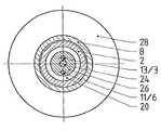
도 2는 도 1의 선 I-I을 따라 절단한 횡단면이고,FIG. 2 is a cross section taken along line I-I of FIG. 1,
도 3은 도 1의 선 II-II를 따라 절단한 횡단면이며,3 is a cross section taken along line II-II of FIG. 1,
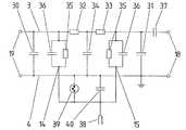
도 4는 도 1에 따른 장치의 등가 회로도이고,4 is an equivalent circuit diagram of the apparatus according to FIG. 1,
도 5는 추가의 고역 통과 필터를 구비한 도 1에 따른 장치의 등가 회로도이며,5 is an equivalent circuit diagram of the device according to FIG. 1 with an additional high pass filter, FIG.
도 6은 추가의 고역 통과 필터 및 추가의 유도 소자 및 DC-공급부를 구비한 도 1에 따른 장치의 등가 회로도이다.6 is an equivalent circuit diagram of the device according to FIG. 1 with an additional high pass filter and an additional induction element and a DC supply.
도 1은 양측에 동축 케이블을 위한 커넥터(7, 8)를 구비한 본 발명에 따른 서어지 보호 필터 및 피뢰침 장치(1)를 보여준다. 동축 케이블은 도시되어 있지 않으며, 예를 들어 상응하는 장치를 갖춘 송수신 장치와 안테나 사이의 연결부로서 이용된다. 커넥터(7, 8)는 부분적으로 규격화된 공지된 소자이고, 한편으로는 케이블의 내부 도체를 소자(21)를 통해 장치(1)의 내부 도체(3)와 연결시키고, 다른 한편으로는 케이블의 외부 도체를 기계적 연결부(22)를 통해 하우징(2)과 연결시키기 위해 입력측(19) 및 출력측(18)에 연결 소자를 포함한다. 이 경우 하우징(2)은 장치(1)의 외부 도체(4)를 형성한다. 연결 소자(21)는 장치(1) 또는 하우징(2)의 양 종축(9)에 배치되고, 절연체 플레이트(23)를 통해 하우징 내에 지지된다. 연결 소자(21)의 내부(24)는 도전성이고, 예를 들어 나사 결합, 납땜 또는 수축 방식에 의해 각각 하나의 플레이트(24, 25)와 연결된다. 상기 플레이트(25, 26)는 도전성 재료, 특히 금속, 예컨대 놋쇠로부터 형성된다. 상기 2개의 플레이트(25, 26)는 하우징(2)의 종축(9)의 방향으로 상호 간격을 두고 배치되어 있고, 내부 도체(3)와 2개 단락 도체(5, 6) 사이에 연결부(12, 13)를 형성한다. 내부 도체(3)는 하우징(2)의 종축(9)에 대해 평행하게 그리고 상기 종축에 대해 간격을 두고 배치되어 있다. 도시된 실시예에서는 예를 들어 장치(1)의 전체 내부 도체가 연결 소자(21), 플레이트(25 및 26), 그리고 내부 도체(3)로 이루어진다. 내부 도체가 자체의 길이에 걸쳐 상이한 구조적 차이를 나타냄으로써, 다양한 리액턴스값, 및 유도성 레지스터 및 커패시터가 형성될 수 있다. 2개의 단락 도체(5, 6)도 마찬가지로 하우징(2)의 종축(9)에 대해 대략 평행하게 그리고 상기 종축에 대해 간격을 두고 배치되어 있다. 상기 2개 단락 도체(5, 6)의 외부 단부(10, 11)는 플레이트(25, 26)를 통해 내부 도체(3) 및 연결 소자(21)와 연결된다. 상기 2개 단락 도체(5, 6)의 내부 단부(14, 15)는 상호 마주보도록 정렬되고, 연결 소자(16)를 통해 하우징(2)과 도전 결합된다. 도시된 실시예에서 2개의 단락 도체(5 및 6) 및 연결 소자(16)는 일체로 형성된다. 2개 단락 도체(5, 6) 및 플레이트(25, 26)의 관련 부분은 내부 도체(3)와 하우징(2) 사이에 단락 결합을 형성한다. 공지된 방식으로 상기 부품들의 구조적인 치수를 매칭시키고 유전체(20)를 선택함으로써, 주파수 범위 및 대역폭이 장치의 원하는 사용 분야를 위해 결정될 수 있다. 전기 특성을 개선시키기 위해, 내부 도체(3) 및 단락 도체(5, 6)는 적어도 부분적으로 절연체-바디(27)에 의해 둘러싸여 있다. 부분 영역 중에서 하우징(2)과 내부 도체(3) 사이 그리고 단락 도체(5, 6)와 플레이트(25, 26) 사이에는 유전체로서 공기가 존재한다. 예를 들어 관통 방식에 의해 도전성 장치 벽 내부에 삽입 및 고정시킬 목적으로, 하우징(2)에는 플랜지(28) 및 나사 결합부(29)가 설치된다. 펄스의 유도는 전위 보상을 막는 상기 도전성 장치 벽을 통해 이루어진다.1 shows a surge protection filter and
도 2에는 도 1의 선 I-I을 따라 절단한 장치(1)의 횡단면이 도시되어 있다. 도면에서는, 그 중앙에 연결 소자(21)의 내부(24)가 삽입되어 연결된 플레이트(26)를 볼 수 있다. 단락 도체(6)의 외부 단부(11) 및 내부 도체(3)의 영역(13)도 마찬가지로 플레이트(26)와 연결되어 외부로 이동된다. 플레이트(26)는 하우징(2)에 의해서 동심으로 둘러싸여 있고, 플레이트(26)와 하우징(2) 사이에는 유전체(20), 상기 영역에서는 공기가 존재한다.FIG. 2 shows a cross section of the
도 3은 장치(1)의 추가 횡단면, 특히 도 1의 선 II-II를 따라 절단한 횡단면을 보여준다. 도면에서는 내부 도체(3) 및 단락 도체(6)를 볼 수 있는데, 상기 도체들은 대략 서로 평행하게 그리고 종축(9)에 대해 평행하게 진행한다. 내부 도체(3) 및 단락 도체(5, 6)는 유전체(20) 내부에 매립되어 있으며, 상기 유전체는 상기 영역에서 절연체 바디(27)에 의해 형성되고, 예를 들어 테플론 재료로 이루어진다.3 shows a further cross section of the
도 1 내지 3에 예로서 도시되고 기술된 바와 같은 본 발명에 따른 서어지 보호 필터 및 피뢰침 장치는 콤팩트한 최소 구조 치수를 갖는다. 상기 장치는 라인이 큰 패킹 밀도를 가능하게 하고, 전술한 부품들을 필요로 하지 않는다. 하우징(2) 및 전체 장치(1)는 실린더 형태로 형성되어 원형 보어 내부로 삽입될 수 있고, 배치 방향을 고려할 필요가 없다. 나란히 배치된 라인 삽입부는 개별 장치(1)의 소자들이 상호 장해를 일으키거나 또는 손상되지 않으면서, 옆에 밀착 배치될 수 있다. 이와 같은 구성 형태는 간단한 방식으로 수축 파이프에 의해 환경 영향에 대해 보호될 수 있다. 그와 동시에 본 발명에 따른 장치(1)는 현저하게 감소된 잔류 펄스 및 잔류 에너지를 갖는다. 예로 도시된 서어지 보호 필터 및 피뢰침 장치(1)가 파형 8/20㎲로 규격화된 충격 전류를 받으면, 25 kA에서 예를 들어 약 16 V 및 약 13 μJ의 전압 잔류 펄스가 유지된다. 동일한 주파수 대역을 위해 직각으로 돌출하는 λ/4 단락 도체를 구비한 종래의 장치가 동일한 테스트를 거치게 되면, 상기 종래의 장치는 25 kA에서 예를 들어 약 70 V 및 약 430 μJ의 전압 잔류 펄스를 갖는다. 그와 동시에 본 발명에 따라 예로 도시된 장치(1)는 1.7 내지 2.5 GHz의 주파수 범위를 위해 광대역으로 설계된다. 상기와 같은 광대역 설계는 대략 400 MHz의 전체 사용 범위에서 플러그 커넥터의 상부 한계 주파수까지 사용될 수 있다. 도시된 예의 하우징(2)의 외부 직경은 상기 플러그 커넥터(29)와 함께 29 mm에 달하고, 상기 연결 소자(21)에 걸친 장치(1)의 전체 길이는 대략 72 mm이다. 사용 분야 및 플러그 커넥터, 그리고 전송될 고주파수 범위에 따라 치수는 상응하게 변동된다.The surge protection filter and lightning arrester device according to the invention as shown and described by way of example in FIGS. 1 to 3 have a compact minimum structural dimension. The device allows for a large packing density of lines and does not require the aforementioned components. The
도 4는 도 1에 따른 고주파 기술적인 장치(1)의 등가 회로도를 보여준다. 입력측(19)과 출력측(18) 사이에서는 내부 도체(3) 및 외부 도체(4)가 뻗는다. 이 경우 입력측 및 출력측(19, 18)은 펄스의 방향에 따라 정해진다. 즉, 입력측(19)은 예를 들어 안테나 쪽으로 향하고, 출력측(18)은 보호될 장치 쪽으로 향한다. 내부 도체(3)에 의해 형성된 주 경로는 커패시터(30), 유도성 레지스터(32), 커패시터(34), 유도성 레지스터(33) 및 추가 커패시터(31)를 포함한다. 상기 장치들은 상이한 리액턴스값을 갖는다. 단락 도체(5, 6)는 등가 회로도에서 각각 유도성 레지스터(35) 및 병렬 접속된 커패시터(36)로 도시되어 있다. 외부 도체(4) 및 하우징(2)은 접지에 접속된다.FIG. 4 shows an equivalent circuit diagram of the high frequency
도 5에는 도 4에서와 동일한 등가 회로도가 도시되어 있으나, 메인 레인 또는 내부 도체(3)의 출구(18) 앞에 추가로 커패시터(37)가 형성되어 있다. 상기 커패시터(37)는 공지된 방식으로 고역 통과 필터를 형성하고, 잔류 에너지를 더욱 감소시키기 위해서 이용된다.5 shows the same equivalent circuit diagram as in FIG. 4, but with an
도 6은, 정전류 공급부(38)가 제공된 본 발명에 따른 장치(1)의 등가 회로도를 보여준다. 도 4 및 5에 기술된 대체 부품들에 추가적으로, 본 발명에 따른 장치는 추가의 펄스 유도 소자(39) 및 추가의 커패시터(40)를 포함한다. 추가 펄스 유도 소자(39)로서는 가스 방전 도체, 배리스터 또는 다이오드가 사용될 수 있다. 상기 유도 소자(39)는 단락 도체(5 및 6)의 출력측(14, 15)과 외부 도체(4), 또는 하우징(2) 사이에 접속된다. 이 경우 상기 추가 유도 장치(39)는 전송 가능한 주파수 범위에서 해체된다.6 shows an equivalent circuit diagram of a
도 4 내지 6의 등가 회로도에 도시된 별도의 사용 부품들은 실제로 존재할 수 있거나 또는 도 1에 따른 실시예에 도시된 바와 같은 다양한 라인 길이 및 임피이던스로 구현될 수 있다.Separate use parts shown in the equivalent circuit diagrams of FIGS. 4 to 6 may actually exist or may be implemented with various line lengths and impedances as shown in the embodiment according to FIG. 1.
Claims (11)
Translated fromKoreanApplications Claiming Priority (3)
| Application Number | Priority Date | Filing Date | Title |
|---|---|---|---|
| CH2089/00 | 2000-10-25 | ||
| CH20892000 | 2000-10-25 | ||
| PCT/CH2001/000617WO2002035659A1 (en) | 2000-10-25 | 2001-10-15 | Surge protection filter and lightning conductor system |
Publications (2)
| Publication Number | Publication Date |
|---|---|
| KR20030060919A KR20030060919A (en) | 2003-07-16 |
| KR100569637B1true KR100569637B1 (en) | 2006-04-10 |
Family
ID=4567459
Family Applications (1)
| Application Number | Title | Priority Date | Filing Date |
|---|---|---|---|
| KR1020037005679AExpired - Fee RelatedKR100569637B1 (en) | 2000-10-25 | 2001-10-15 | Surge Protection Filters and Lightning Rod Devices |
Country Status (10)
| Country | Link |
|---|---|
| US (1) | US6950294B2 (en) |
| EP (1) | EP1329005B1 (en) |
| KR (1) | KR100569637B1 (en) |
| CN (1) | CN1255908C (en) |
| AT (1) | ATE377859T1 (en) |
| AU (1) | AU2001293603A1 (en) |
| CA (1) | CA2426855C (en) |
| DE (1) | DE50113240D1 (en) |
| ES (1) | ES2199703T3 (en) |
| WO (1) | WO2002035659A1 (en) |
Families Citing this family (20)
| Publication number | Priority date | Publication date | Assignee | Title |
|---|---|---|---|---|
| ATE368947T1 (en)* | 2002-06-26 | 2007-08-15 | Huber+Suhner Ag | INTERFERENCE FILTER AND LIGHTNING CURRENT ARRESTER DEVICE |
| RU2251191C2 (en)* | 2002-11-15 | 2005-04-27 | Корпорация "Самсунг Электроникс" | Pulse surge protective gear |
| US20050099754A1 (en)* | 2003-11-12 | 2005-05-12 | Raido Frequency Systems, Inc. | Impedance matched surge protected coupling loop assembly |
| DE502006006427D1 (en)* | 2005-02-15 | 2010-04-29 | Spinner Gmbh Elektrotech | Coaxial surge arrester |
| US7349191B2 (en)* | 2005-09-01 | 2008-03-25 | Andrew Corporation | Offset planar coil coaxial surge suppressor |
| US7324318B2 (en)* | 2005-10-07 | 2008-01-29 | Andrew Corporation | Multiple planar inductor coaxial surge suppressor |
| US20070097583A1 (en)* | 2005-10-31 | 2007-05-03 | Andrew Corporation | Tuned Coil Coaxial Surge Suppressor |
| US7483251B2 (en)* | 2006-01-13 | 2009-01-27 | Andrew Llc | Multiple planar inductive loop surge suppressor |
| US7583489B2 (en)* | 2006-05-22 | 2009-09-01 | Andrew Llc | Tungsten shorting stub and method of manufacture |
| US8174132B2 (en)* | 2007-01-17 | 2012-05-08 | Andrew Llc | Folded surface capacitor in-line assembly |
| US8456789B2 (en) | 2010-12-15 | 2013-06-04 | Andrew Llc | Tunable coaxial surge arrestor |
| FR2984031B1 (en)* | 2011-12-12 | 2013-11-22 | Sagemcom Broadband Sas | INTEGRATED TRIPOLAR PARAFOUDRE IN A RESIDENTIAL GATEWAY WITH LIGHTNING IMPACT DETECTOR |
| WO2016200700A1 (en) | 2015-06-09 | 2016-12-15 | Transtector Systems, Inc. | Sealed enclosure for protecting electronics |
| US10588236B2 (en) | 2015-07-24 | 2020-03-10 | Transtector Systems, Inc. | Modular protection cabinet with flexible backplane |
| US10356928B2 (en) | 2015-07-24 | 2019-07-16 | Transtector Systems, Inc. | Modular protection cabinet with flexible backplane |
| US9924609B2 (en) | 2015-07-24 | 2018-03-20 | Transtector Systems, Inc. | Modular protection cabinet with flexible backplane |
| CN105161806B (en)* | 2015-08-14 | 2018-01-16 | 深圳市迈特通信设备有限公司 | A kind of lightning protection plastic filter |
| US10193335B2 (en) | 2015-10-27 | 2019-01-29 | Transtector Systems, Inc. | Radio frequency surge protector with matched piston-cylinder cavity shape |
| US9991697B1 (en) | 2016-12-06 | 2018-06-05 | Transtector Systems, Inc. | Fail open or fail short surge protector |
| CN110556805A (en)* | 2019-09-26 | 2019-12-10 | 深圳市速联技术有限公司 | Ultra-wideband radio frequency coaxial lightning electromagnetic pulse protection method and device |
Family Cites Families (8)
| Publication number | Priority date | Publication date | Assignee | Title |
|---|---|---|---|---|
| DE2015445B2 (en)* | 1970-04-01 | 1972-10-05 | ADAPTERS FOR COAXIAL CONNECTIONS, IN PARTICULAR FOR REMOTE INFORMATION | |
| US5053910A (en)* | 1989-10-16 | 1991-10-01 | Perma Power Electronics, Inc. | Surge suppressor for coaxial transmission line |
| CH690146A5 (en)* | 1995-03-31 | 2000-05-15 | Huber+Suhner Ag | EMP filter in a coaxial line. |
| DE19520974A1 (en)* | 1995-06-08 | 1996-12-12 | Spinner Gmbh Elektrotech | Overvoltage protection for HF lines |
| JP4171995B2 (en)* | 1997-10-16 | 2008-10-29 | 潤 福原 | Flicker sensitivity distribution measuring device and computer-readable recording medium recording flicker sensitivity distribution measuring program |
| AU740311B2 (en)* | 1998-02-17 | 2001-11-01 | Huber & Suhner Ag | EMP - charge eliminator |
| WO2002103875A1 (en)* | 2001-06-15 | 2002-12-27 | Kauffman George M | Protective device |
| US6785110B2 (en)* | 2001-10-12 | 2004-08-31 | Polyphaser Corporation | Rf surge protection device |
- 2001
- 2001-10-15CACA002426855Apatent/CA2426855C/ennot_activeExpired - Fee Related
- 2001-10-15ATAT01973942Tpatent/ATE377859T1/ennot_activeIP Right Cessation
- 2001-10-15USUS10/399,187patent/US6950294B2/ennot_activeExpired - Fee Related
- 2001-10-15EPEP01973942Apatent/EP1329005B1/ennot_activeExpired - Lifetime
- 2001-10-15AUAU2001293603Apatent/AU2001293603A1/ennot_activeAbandoned
- 2001-10-15DEDE50113240Tpatent/DE50113240D1/ennot_activeExpired - Fee Related
- 2001-10-15KRKR1020037005679Apatent/KR100569637B1/ennot_activeExpired - Fee Related
- 2001-10-15WOPCT/CH2001/000617patent/WO2002035659A1/enactiveIP Right Grant
- 2001-10-15CNCNB018180361Apatent/CN1255908C/ennot_activeExpired - Fee Related
- 2001-10-15ESES01973942Tpatent/ES2199703T3/ennot_activeExpired - Lifetime
Also Published As
| Publication number | Publication date |
|---|---|
| US6950294B2 (en) | 2005-09-27 |
| EP1329005B1 (en) | 2007-11-07 |
| EP1329005A1 (en) | 2003-07-23 |
| CA2426855C (en) | 2006-12-12 |
| KR20030060919A (en) | 2003-07-16 |
| WO2002035659A1 (en) | 2002-05-02 |
| CN1471752A (en) | 2004-01-28 |
| ES2199703T1 (en) | 2004-03-01 |
| AU2001293603A1 (en) | 2002-05-06 |
| ES2199703T3 (en) | 2008-04-16 |
| CA2426855A1 (en) | 2004-04-24 |
| DE50113240D1 (en) | 2007-12-20 |
| ATE377859T1 (en) | 2007-11-15 |
| US20040100751A1 (en) | 2004-05-27 |
| CN1255908C (en) | 2006-05-10 |
Similar Documents
| Publication | Publication Date | Title |
|---|---|---|
| KR100569637B1 (en) | Surge Protection Filters and Lightning Rod Devices | |
| US6754060B2 (en) | Protective device | |
| US6456478B1 (en) | Broad-band EMP surge diverter | |
| US6721155B2 (en) | Broadband surge protector with stub DC injection | |
| CA2027655C (en) | Lightning protection apparatus for rf equipment and the like | |
| US7609502B2 (en) | Protective device | |
| US7092230B2 (en) | Interference filter and lightning conductor device | |
| US7170728B2 (en) | Surge suppressor with increased surge current capability | |
| CA2182794C (en) | Coaxial transmission line surge arrestor | |
| EP1137095B1 (en) | Broadband shorted stub surge protector | |
| WO2002041460A1 (en) | Surge protected coaxial termination | |
| US6636407B1 (en) | Broadband surge protector for RF/DC carrying conductor | |
| CA2227960C (en) | Emp-charge-eliminator | |
| RU2137275C1 (en) | Lightning arrester for coaxial transmission line | |
| US5764114A (en) | EMP-filter in a coaxial line | |
| CN117438886A (en) | Protective equipment against pulse currents | |
| KR200302579Y1 (en) | A arrester having radial insulators | |
| KR100514199B1 (en) | Antenna arrestor for mobile telephone station |
Legal Events
| Date | Code | Title | Description |
|---|---|---|---|
| PA0105 | International application | St.27 status event code:A-0-1-A10-A15-nap-PA0105 | |
| P11-X000 | Amendment of application requested | St.27 status event code:A-2-2-P10-P11-nap-X000 | |
| P13-X000 | Application amended | St.27 status event code:A-2-2-P10-P13-nap-X000 | |
| PG1501 | Laying open of application | St.27 status event code:A-1-1-Q10-Q12-nap-PG1501 | |
| A201 | Request for examination | ||
| P11-X000 | Amendment of application requested | St.27 status event code:A-2-2-P10-P11-nap-X000 | |
| P13-X000 | Application amended | St.27 status event code:A-2-2-P10-P13-nap-X000 | |
| PA0201 | Request for examination | St.27 status event code:A-1-2-D10-D11-exm-PA0201 | |
| E902 | Notification of reason for refusal | ||
| PE0902 | Notice of grounds for rejection | St.27 status event code:A-1-2-D10-D21-exm-PE0902 | |
| P11-X000 | Amendment of application requested | St.27 status event code:A-2-2-P10-P11-nap-X000 | |
| P13-X000 | Application amended | St.27 status event code:A-2-2-P10-P13-nap-X000 | |
| E701 | Decision to grant or registration of patent right | ||
| PE0701 | Decision of registration | St.27 status event code:A-1-2-D10-D22-exm-PE0701 | |
| GRNT | Written decision to grant | ||
| PR0701 | Registration of establishment | St.27 status event code:A-2-4-F10-F11-exm-PR0701 | |
| PR1002 | Payment of registration fee | St.27 status event code:A-2-2-U10-U12-oth-PR1002 Fee payment year number:1 | |
| PG1601 | Publication of registration | St.27 status event code:A-4-4-Q10-Q13-nap-PG1601 | |
| LAPS | Lapse due to unpaid annual fee | ||
| PC1903 | Unpaid annual fee | St.27 status event code:A-4-4-U10-U13-oth-PC1903 Not in force date:20090405 Payment event data comment text:Termination Category : DEFAULT_OF_REGISTRATION_FEE | |
| PC1903 | Unpaid annual fee | St.27 status event code:N-4-6-H10-H13-oth-PC1903 Ip right cessation event data comment text:Termination Category : DEFAULT_OF_REGISTRATION_FEE Not in force date:20090405 |