KR100569330B1 - Dust collection unit of vacuum cleaner - Google Patents
Dust collection unit of vacuum cleanerDownload PDFInfo
- Publication number
- KR100569330B1 KR100569330B1KR1020040113377AKR20040113377AKR100569330B1KR 100569330 B1KR100569330 B1KR 100569330B1KR 1020040113377 AKR1020040113377 AKR 1020040113377AKR 20040113377 AKR20040113377 AKR 20040113377AKR 100569330 B1KR100569330 B1KR 100569330B1
- Authority
- KR
- South Korea
- Prior art keywords
- dust collecting
- wall
- collecting unit
- vacuum cleaner
- chamber
- Prior art date
- Legal status (The legal status is an assumption and is not a legal conclusion. Google has not performed a legal analysis and makes no representation as to the accuracy of the status listed.)
- Expired - Fee Related
Links
Images


Classifications
- A—HUMAN NECESSITIES
- A47—FURNITURE; DOMESTIC ARTICLES OR APPLIANCES; COFFEE MILLS; SPICE MILLS; SUCTION CLEANERS IN GENERAL
- A47L—DOMESTIC WASHING OR CLEANING; SUCTION CLEANERS IN GENERAL
- A47L9/00—Details or accessories of suction cleaners, e.g. mechanical means for controlling the suction or for effecting pulsating action; Storing devices specially adapted to suction cleaners or parts thereof; Carrying-vehicles specially adapted for suction cleaners
- A47L9/10—Filters; Dust separators; Dust removal; Automatic exchange of filters
- A47L9/16—Arrangement or disposition of cyclones or other devices with centrifugal action
- A47L9/1616—Multiple arrangement thereof
- A47L9/1625—Multiple arrangement thereof for series flow
- A—HUMAN NECESSITIES
- A47—FURNITURE; DOMESTIC ARTICLES OR APPLIANCES; COFFEE MILLS; SPICE MILLS; SUCTION CLEANERS IN GENERAL
- A47L—DOMESTIC WASHING OR CLEANING; SUCTION CLEANERS IN GENERAL
- A47L9/00—Details or accessories of suction cleaners, e.g. mechanical means for controlling the suction or for effecting pulsating action; Storing devices specially adapted to suction cleaners or parts thereof; Carrying-vehicles specially adapted for suction cleaners
- A47L9/10—Filters; Dust separators; Dust removal; Automatic exchange of filters
- A47L9/16—Arrangement or disposition of cyclones or other devices with centrifugal action
- A47L9/1616—Multiple arrangement thereof
- A47L9/1641—Multiple arrangement thereof for parallel flow
- A—HUMAN NECESSITIES
- A47—FURNITURE; DOMESTIC ARTICLES OR APPLIANCES; COFFEE MILLS; SPICE MILLS; SUCTION CLEANERS IN GENERAL
- A47L—DOMESTIC WASHING OR CLEANING; SUCTION CLEANERS IN GENERAL
- A47L9/00—Details or accessories of suction cleaners, e.g. mechanical means for controlling the suction or for effecting pulsating action; Storing devices specially adapted to suction cleaners or parts thereof; Carrying-vehicles specially adapted for suction cleaners
- A47L9/10—Filters; Dust separators; Dust removal; Automatic exchange of filters
- A47L9/16—Arrangement or disposition of cyclones or other devices with centrifugal action
- A47L9/1683—Dust collecting chambers; Dust collecting receptacles
- B—PERFORMING OPERATIONS; TRANSPORTING
- B04—CENTRIFUGAL APPARATUS OR MACHINES FOR CARRYING-OUT PHYSICAL OR CHEMICAL PROCESSES
- B04C—APPARATUS USING FREE VORTEX FLOW, e.g. CYCLONES
- B04C5/00—Apparatus in which the axial direction of the vortex is reversed
- B04C5/08—Vortex chamber constructions
- B04C5/081—Shapes or dimensions
- B—PERFORMING OPERATIONS; TRANSPORTING
- B04—CENTRIFUGAL APPARATUS OR MACHINES FOR CARRYING-OUT PHYSICAL OR CHEMICAL PROCESSES
- B04C—APPARATUS USING FREE VORTEX FLOW, e.g. CYCLONES
- B04C5/00—Apparatus in which the axial direction of the vortex is reversed
- B04C5/14—Construction of the underflow ducting; Apex constructions; Discharge arrangements ; discharge through sidewall provided with a few slits or perforations
- B04C5/185—Dust collectors
- B—PERFORMING OPERATIONS; TRANSPORTING
- B04—CENTRIFUGAL APPARATUS OR MACHINES FOR CARRYING-OUT PHYSICAL OR CHEMICAL PROCESSES
- B04C—APPARATUS USING FREE VORTEX FLOW, e.g. CYCLONES
- B04C5/00—Apparatus in which the axial direction of the vortex is reversed
- B04C5/24—Multiple arrangement thereof
- Y—GENERAL TAGGING OF NEW TECHNOLOGICAL DEVELOPMENTS; GENERAL TAGGING OF CROSS-SECTIONAL TECHNOLOGIES SPANNING OVER SEVERAL SECTIONS OF THE IPC; TECHNICAL SUBJECTS COVERED BY FORMER USPC CROSS-REFERENCE ART COLLECTIONS [XRACs] AND DIGESTS
- Y10—TECHNICAL SUBJECTS COVERED BY FORMER USPC
- Y10S—TECHNICAL SUBJECTS COVERED BY FORMER USPC CROSS-REFERENCE ART COLLECTIONS [XRACs] AND DIGESTS
- Y10S55/00—Gas separation
- Y10S55/03—Vacuum cleaner
Landscapes
- Engineering & Computer Science (AREA)
- Mechanical Engineering (AREA)
- Physics & Mathematics (AREA)
- Geometry (AREA)
- Filters For Electric Vacuum Cleaners (AREA)
- Injection Moulding Of Plastics Or The Like (AREA)
Abstract
Description
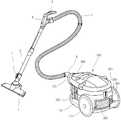
Translated fromKorean도 1은 본 발명의 사상에 따른 진공 청소기의 사시도.1 is a perspective view of a vacuum cleaner according to the spirit of the present invention.
도 2는 본 발명에 따른 진공 청소기 본체의 정면 사시도.Figure 2 is a front perspective view of the vacuum cleaner body according to the present invention.
도 3은 본 발명에 따른 진공 청소기에서 집진유닛의 분리 사시도.Figure 3 is an exploded perspective view of the dust collecting unit in the vacuum cleaner according to the present invention.
도 4는 본 발명에 따른 진공 청소기 본체의 분해 사시도.Figure 4 is an exploded perspective view of the vacuum cleaner body according to the present invention.
도 5는 본 발명에 따른 집진유닛의 분해 사시도.5 is an exploded perspective view of the dust collecting unit according to the present invention.
도 6은 도 3의 Ⅰ-Ⅰ'의 단면도.6 is a cross-sectional view taken along the line II ′ of FIG. 3.
도 7은 본 발명에 따른 집진유닛에서 집진바디의 평면도.7 is a plan view of a dust collecting body in a dust collecting unit according to the present invention.
도 8은 본 발명에 따른 집진유닛에서 집진바디의 수직 단면도.8 is a vertical cross-sectional view of the dust collecting body in the dust collecting unit according to the present invention.
도 9는 본 발명에 따른 진공 청소기의 세로 단면도.9 is a longitudinal cross-sectional view of the vacuum cleaner according to the present invention.
<도면의 주요 부분에 대한 부호의 설명><Explanation of symbols for the main parts of the drawings>
406 : 일체형 집진바디416 : 제 1 저장챔버406: integral dust collection body 416: first storage chamber
417 : 제 2 저장챔버423 : 제 1 분리챔버417: second storage chamber 423: first separation chamber
424 : 제 2 분리챔버437 : 분리판424: second separation chamber 437: separation plate
462 : 에지부462: edge portion
본 발명은 진공 청소기에 관한 것으로서, 제작 과정이 편리하고 간단하게 수행될 수 있는 진공 청소기의 집진유닛에 관한 것이다. 더욱 상세하게는, 집진유닛 내부의 집진바디가 일체형으로서, 단일의 사출 공정으로 제작이 완료됨으로써, 제조과정이 단순하게 되고, 제조원가가 줄어드는 진공 청소기의 집진유닛에 관한 것이다.The present invention relates to a vacuum cleaner, and more particularly, to a dust collecting unit of a vacuum cleaner, in which a manufacturing process can be conveniently and simply performed. More specifically, the present invention relates to a dust collecting unit of a vacuum cleaner, in which a dust collecting body inside the dust collecting unit is integrated and the manufacturing is completed in a single injection process, thereby simplifying the manufacturing process and reducing the manufacturing cost.
진공 청소기는 기기 내부의 진공압에 의해서 흡입되는 공기 중에 포함되는 이물이 걸러지도록 함으로써, 외부 환경에 대한 청소가 수행되도록 하는 기기이다. 한편, 상기 진공 청소기는 흡입된 공기 중에서 이물이 걸러지도록 하기 위해서 진공 청소기의 내부에 소정 형태의 집진유닛이 내장되고, 상기 집진유닛에는 이물이 필터링되도록 하는 필터링 장치가 설치된다.The vacuum cleaner is a device for cleaning the external environment by filtering foreign substances contained in the air sucked by the vacuum pressure inside the device. On the other hand, the vacuum cleaner is provided with a dust collecting unit of a predetermined type inside the vacuum cleaner in order to filter foreign matter from the sucked air, the dust collecting unit is provided with a filtering device for filtering the foreign matter.
상기 필터링 장치의 종류로서 종래부터 있어 온 수단으로서는, 공기가 통과되는 다공성의 재질이 이용되고 있는데, 공기가 상기 다공성 재질의 물품을 통과되는 중에 이물이 걸러지는 필터가 널리 이용되어 왔다.As a kind of the filtering device, a porous material through which air passes has been used as a means conventionally used, and a filter for filtering foreign substances while air passes through the porous material has been widely used.
그러나, 상기 다공성 재질의 필터는 재활용이 불편할 뿐만 아니라, 필터를 청소하기가 어렵기 때문에, 근래들어서는 싸이클론 장치가 주된 필터링 장치로 사용되고 있다. 그러나, 상기 싸이클론 장치는 미세한 이물까지는 걸려지지 못하기 때문에, 싸이클론 장치와 함께 별도의 다공성 재질의 필터가 요구되는 것이 일반적이었다.However, since the filter of the porous material is not only inconvenient to recycle, but also difficult to clean the filter, the cyclone device has recently been used as the main filtering device. However, since the cyclone device is not caught up to the fine foreign matter, it was common to require a separate porous material filter together with the cyclone device.
그러나, 싸이클론 장치와 함께 다공성 재질의 필터가 함께 적용되는 경우에 는, 결국 다공성 재질의 필터를 주기적으로 청소해야 되는 문제가 계속해서 발생되는 단점이 있다. 그리고, 상기 다공성 재질의 필터에 이물이 침착되는 경우에는, 공기의 유속이 저하되어 진공 청소기의 효율이 급감하는 문제점이 있다.However, when the porous filter is applied together with the cyclone device, there is a disadvantage in that the problem of periodically cleaning the filter of the porous material continues to occur. In addition, when foreign matter is deposited on the filter of the porous material, there is a problem that the flow rate of the air is lowered and the efficiency of the vacuum cleaner is sharply reduced.
이러한 문제점을 감안하여 근래들어서는 집진유닛의 내부에 다공성 재질의 필터가 사용되는 대신에, 복수 개의 싸이클론 유동이 단일의 집진유닛 내부에 조성되도록 함으로써, 미세먼지까지 완전하게 필터링되도록 하는 방안이 제안되고 있다. 이러한 집진유닛을 멀티 싸이클론 집진유닛이라고 말할 수 있다.In view of these problems, in recent years, instead of using a porous filter inside the dust collecting unit, a method of completely filtering even fine dust is proposed by allowing a plurality of cyclone flows to be formed inside a single dust collecting unit. have. Such a dust collecting unit may be referred to as a multi-cyclone dust collecting unit.
한편, 멀티 싸이클론 집진유닛은, 집진유닛의 내부에 다수개의 사이클론 유동이 만들어지도록 하기 위하여, 공기의 유동이 여러 방향으로 전환되는 등의 요인으로 인하여, 집진유닛의 내부 구성이 복잡하게 이루어져 있다. 이러한 요인으로 인하여 멀티 싸이클론 집진유닛이 만들어지기 위해서는, 다수개의 부품이 서로 결합되어 만들어지는 것이 일반적이다.On the other hand, in the multi-cyclone dust collecting unit, the internal configuration of the dust collecting unit is complicated due to factors such as the flow of air being diverted in various directions so that a plurality of cyclone flows are made inside the dust collecting unit. Due to these factors, in order to make a multi-cyclone dust collecting unit, it is common that a plurality of parts are made by combining with each other.
그러나, 다수 개의 부품이 조립되는 과정으로 거쳐서 집진유닛이 만들어지면, 그 만큼 제품에서 불량이 발생될 가능성이 높아지고, 작업자의 수고가 늘어나는 문제점이 발생한다.However, if the dust collecting unit is made through a process of assembling a plurality of parts, the likelihood of a defect occurring in the product increases as much, and the trouble of the worker increases.
본 발명은 상기되는 문제점을 해결하기 위하여 제안되는 것으로서, 집진유닛이 소수개의 부품으로 제작되도록 함으로서, 제품의 신뢰성이 향상될 수 있는 진공 청소기의 집진유닛을 제안하는 것을 목적으로 한다.The present invention is proposed to solve the above problems, and it is an object of the present invention to propose a dust collecting unit of a vacuum cleaner that can improve the reliability of the product by making the dust collecting unit is made of a few parts.
또한, 집진유닛의 내부 구성이 최소한의 부품으로 제작되도록 함으로써, 제 품의 정밀도가 향상되고, 집진유닛의 집진효율이 향상될 수 있는 진공 청소기의 집진유닛을 제안하는 것을 목적으로 한다.In addition, it is an object of the present invention to propose a dust collecting unit of a vacuum cleaner by making the internal configuration of the dust collecting unit to be made with a minimum of parts, the accuracy of the product can be improved, the dust collecting efficiency of the dust collecting unit can be improved.
상기되는 목적을 달성하기 위한 본 발명에 따른 진공 청소기의 집진유닛은, 싸이클론 유동이 형성되고, 단일의 몸체를 이루는 복수 개의 분리챔버(423)(424); 및 상기 분리챔버(423)(424)와 한 몸으로 상기 분리챔버(423)(424)와 함께 성형되는 저장챔버(416)(417)가 포함된다.Dust collecting unit of the vacuum cleaner according to the present invention for achieving the above object, the cyclone flow is formed, a plurality of
본 발명의 다른 측면에 따른 진공 청소기의 집진유닛은 분리판(437); 상기 분리판(437)의 하방으로 연장되는 내벽(420)의 내부 공간에 제공되는 제 1 분리챔버(423); 상기 내벽(420)의 이격되는 외부에 놓이는 중간벽(419)의 사이 공간으로 정의되는 제 2 저장챔버(417); 상기 중간벽(419)의 이격되는 외부에 놓이는 외벽(418)의 내부공간에 제공되는 제 1 저장챔버(416); 및 상기 분리판(437)의 상방 및 하방으로 연장되어, 하단부가 상기 제 2 저장챔버(417)의 내부에 수용되는 제 2 분리챔버(424)가 단일의 몸체로 성형되는 것을 특징으로 한다.Dust collecting unit of the vacuum cleaner according to another aspect of the present invention is a
제안되는 바와 같은 본 발명의 진공 청소기의 집진유닛에 의해서, 종래에 제기되었던 불량품의 문제와, 제품의 정밀도 저하, 제조경비의 상승등의 문제가 해소될 수 있는 장점이 있다.By the dust collecting unit of the vacuum cleaner of the present invention as proposed, there is an advantage that problems such as the problem of defective products, decrease in precision of the product, increase in manufacturing cost, which have been raised in the related art, can be solved.
이하에서는 도면을 참조하여 본 발명의 바람직한 구체적 실시예를 상세하게 설명한다.Hereinafter, exemplary embodiments of the present invention will be described in detail with reference to the accompanying drawings.
도 1은 본 발명의 사상에 따른 진공 청소기의 사시도이다.1 is a perspective view of a vacuum cleaner according to the spirit of the present invention.
도 1을 참조하면, 본 발명의 진공 청소기에는 진공 청소기 본체(100)와, 상기 진공 청소기 본체(100)의 흡입측에 연결되는 흡입관로가 포함된다. 상기 진공 청소기 본체(100)의 내부에는 적어도 흡입팬 및 집진유닛이 놓여서, 흡입된 공기 중에서 이물이 걸려져 깨끗해진 뒤에, 외부로 배출된다.Referring to FIG. 1, the vacuum cleaner of the present invention includes a
상기 흡입관로는 상기 진공 청소기 본체(100)의 흡인력에 의해서 공기와 함께 이물이 흡입되는 관로이다. 상세하게, 상기 흡입관로는 강한 공기 유동에 의해서 외부로부터 공기와 함께 이물 및 먼지가 흡입되도록 하는 흡입 노즐체(1)와, 상기 흡입 노즐체(1)로부터 연장되고 사용자의 사용 상태에 따라서 길이가 신축적으로 늘어나는 연장관(2)과, 상기 연장관(2)의 단부에 제공되는 동작 핸들(3)과, 상기 동작 핸들(3)의 전방에 사용자의 손이 닿는 부분에 제공되는 조작부(4)와, 상기 동작 핸들(3)에서 후방으로 더 연장되고 사용자의 위치에 따라서 구부러지는 플렉시블 관(5)과, 상기 플렉시블 관(5)의 단부에서 상기 진공 청소기 본체(100)와 연결되는 커넥터(6)와, 상기 연장관(2) 또는 흡입 노즐체(1)의 소정 위치에 놓여 진공 청소기가 사용되지 않을 때 연장관(2)이 거치되도록 하기 위한 연장관 걸이(7)가 포함된다.The suction pipe is a pipe in which foreign matter is sucked together with air by the suction force of the vacuum cleaner
상기 커넥터(6)는 상기 조작부(4)로부터 입력된 사용자의 조작 신호가 진공 청소기 본체(100)로 인가되도록 하기 위한 연결단자의 기능과, 흡입된 공기가 진공 청소기 본체(6)로 유입되도록 하는 기능이 동시에 수행된다. 이를 위하여, 상기 커넥터(6)의 단부에는 복수개의 전기 연결단이 더 제공된다. 한편, 상기 커넥터(6)는 흡입관로의 어느 부분에 상기 조작부(4)가 놓일 경우에만 필요한 것으로서, 본원 발명은 이에 제한되지 아니한다. 즉, 상기 조작부(4)가 진공 청소기 본체(100)의 어느 곳에 형성되는 경우에, 커넥터(6)는 상기 신호 연결단이 없이 공기의 유입통로로서의 기능만이 수행되도록 할 수도 있다.The
또한, 상기 흡입관로를 통하여 상기 진공 청소기 본체(100)로 유입된 공기는, 상기 진공 청소기 본체(100)의 내부에서 이물이 걸러지고 깨끗해진 뒤에, 진공 청소기 본체(100)의 외부로 배출된다. 이하에서는 진공 청소기 본체(100)의 구성을 설명한다.In addition, the air introduced into the vacuum cleaner
도 2는 진공 청소기 본체의 정면 사시도이다.2 is a front perspective view of the vacuum cleaner body.
도 1과 도 2를 참조하여 진공 청소기 본체의 구성을 설명하면, 상기 진공 청소기 본체(100)에는, 상기 본체(100)의 바닥면에 제공되는 제 1 베이스(110)와, 상기 제 1 베이스(110)의 직근 상측에 놓이는 제 2 베이스(150)와, 상기 본체(100)의 후부의 양측에 제공되어 진공 청소기 본체(100)의 이동이 원활하게 수행되도록 하는 바퀴(111)와, 상기 진공 청소기 본체(100)의 상측부에 제공되는 커버(200)와, 본체(100)의 전방부에서 상기 커버(200)와 상기 베이스(110)(150)가 연결되어 양자간에 견고하게 지지되는 전방 서포터(170)가 포함된다.Referring to FIGS. 1 and 2, the structure of the vacuum cleaner body will be described. In the
상기 전방 서포터(170)에는 상기 커넥터(6)가 연결되어 외기가 흡입되도록 하는 것은 물론이다. 그리고, 상기 전방 서포터(170)는 진공 청소기 본체(100)의 전방부의 형상이 견고하게 지지되도록 한다.Of course, the
상기 제 2 베이스(150)는 상기 제 1 베이스(110)의 직근 상방에 제공되어 제품의 형상이 미려하게 유지되고, 진공 청소기 본체(100)의 하측부의 강도가 증가되 도록 한다.The
상기 커버(200)의 후방에는 본체 배기구(302)가 형성되는 배기커버(301)가 제공되어, 진공 청소기 본체(100)에 의해서 깨끗해진 공기가 배출된다. 그리고, 상기 커버(200)의 상면에는 소정의 힌지점을 중심으로 회전이 가능한 이동핸들(201)이 형성된다. 상기 이동핸들(201)은 사용자의 조작에 의해서 움직임으로써, 진공 청소기 본체(100)를 이동시키고자 할 때에는 직립되고 보관시에는 뉘어져 있도록 함으로써, 사용자가 편리하게 사용할 수 있다.An
상기 전방 서포터(170)의 후방에는 집진유닛(400)이 안착되어 외기가 유입되고, 상기 집진유닛(400)의 내부에는 싸이클론 유동에 의해서 이물이 걸러지도록 하는 싸이클론 부재가 수용된다.At the rear of the
도 3에 제시되는 바와 같이, 상기 집진유닛(400)은 진공 청소기 본체(100) 내부의 집진 유닛 수용부(151)에 상하 방향으로 안착된다. 그러므로, 장착시에는 하방으로 누르고, 탈거시에는 상측으로 당기면 된다.As shown in FIG. 3, the
상기 전방 서포터(170)에는 본체 흡입구(171)가 형성되고, 상기 본체 흡입구(171)와 정렬되는 상기 집진유닛(400) 상의 대응되는 위치에는 집진유닛 흡입구(401)가 위치한다. 그리고, 집진유닛(400)에서 상기 집진유닛 흡입구(401)와 반대되는 방향에는 배출구가 형성된다. 그리고, 상기 배출구는 모터측 흡입구(172)와 정렬되어 집진유닛(400)을 통과하며 깨끗해진 공기가 모터측으로 흡입된다.The
특히, 상기 배출구와 상기 모터측 흡입구(172)는 진공 청소기 본체(100)의 크기를 줄이고 공기가 원활히 유동되도록 하기 위하여 납작한 직 사각형의 형상으 로 제공된다.In particular, the outlet and the
도 4는 본 발명에 따른 진공 청소기 본체의 분해 사시도이다.4 is an exploded perspective view of the vacuum cleaner body according to the present invention.
도 4를 참조하면, 상기 제 1 베이스(110)의 상측부에서 앞쪽에는 상기 제 2 베이스(150)가 놓이고, 뒷쪽에는 상기 모터 하우징(300)이 놓인다. 그리고, 순차적으로 상기 커버(200)가 덮혀져서 진공 청소기의 본체(100)가 이루어진다.Referring to FIG. 4, the
여기서, 상기 커버(200)는 상기 전방 서포터(170)가 별도의 부분으로서 상기 커버(200)에 체결된 상태에서, 상기 베이스(110)(150)에 결합된다. 그리고, 상기 모터 하우징(300)에서는 상기 모터측 흡입구(172)를 통하여 흡입된 공기가 유동 방향이 수직으로 꺾여서 하방으로 유입된다. 그리고, 유입된 공기는 모터 하우징(300)에서 유동 방향이 수평으로 꺾여서 후방으로 배출되도록 한다.Here, the
도 5는 본 발명에 따른 집진유닛의 분해 사시도이다.5 is an exploded perspective view of the dust collecting unit according to the present invention.
도 5를 참조하면, 본 발명의 집진 유닛(400)은 스펀지등과 같은 다공성의 필터가 사용되지 아니하고, 싸이클론 유동에서 이물이 걸러지도록 한다. 그리고, 상기 싸이클론 유동은 서로 분리되는 두개소 이상의 분리챔버에서 각각 수행되도록 하여, 공기 중의 미세먼지까지 완전하게 필터링되도록 하는 것에 일 특징이 있다.Referring to FIG. 5, the
상세하게 설명하면, 복수 개의 이물분리챔버(도 6의 423, 424참조)와 복수개의 이물저장챔버(도 6의 417, 416참조)가 한 몸으로 형성되는 집진바디(406)와, 상기 집진바디(406)의 하측부에 밀폐로 제공되어, 상기 이물저장챔버(416)(417)에 저장되는 이물이 누설되지 않도록 하는 챔버 실링부(415)(402)와, 상기 집진바디(406)의 상방에 놓여서 집진바디(406)에서 배기되는 공기의 유동이 가이드 되는 배기부(407)와, 상기 배기부(407)의 상방에 소정의 간격으로 제공되어 배기부(407)를 통과한 공기가 일 방향으로 향하도록 하는 간격부(408)와, 상기 간격부(408)의 상방에 놓이는 커버구조(409)(410)(411)(412)가 포함된다.In detail, a
특히, 상기 집진바디(406)는 전체로서의 물품이 단일의 사출과정으로 제조됨으로써, 제작과정이 단순화되고, 작업자의 수고가 줄어들고, 제조경비가 줄어드는 장점을 얻을 수 있다. 이와 같이 상기 집진바디(406)가 일체형으로 제조되는 경우에는, 상기 제 1 저장챔버(416), 제 2 저장챔버(417), 제 1 분리챔버(423), 제 2 분리챔버(424) 및 상기 분리판(437)이 일체로 제작된다.In particular, the
또한, 상기 커버구조는 모체를 이루는 제 1 커버(410)와, 상기 제 1 커버(410)의 전방 및 후방에 각각 놓이는 제 3 커버(412) 및 제 2 커버(409)와, 상기 제 1 커버(410)와 제 2 커버(409)가 같이 고정되도록 하는 커버 삽지구(411)가 포함된다. 상기 커버 삽지구(411)는 상기 제 1 커버(410) 상면부의 일부분을 덮어서 외관이 아름답게 구현되고, 상기 제 1 커버(410) 및 제 2 커버(409)가 동시에 고정되도록 하는 기능이 수행된다.In addition, the cover structure includes a
상기 집진바디(406)의 내부에는, 싸이클론 유동에서 오물 분리가 원활히 수행되도록 하는 원추형 필터(405)와, 상기 원추형 필터(405)의 하방에 놓여서 포집된 이물의 재비산을 방지하는 차단부(404), 상기 차단부(404)의 하방에 형성되어 회전운동되는 공기의 유속을 느리게 하여, 이물이 오물저장챔버의 내부에 가라앉도록 하는 유동방지판(403)이 더 형성된다. 여기서 상기 차단부(404)와 상기 유동방지판(403)은 한 몸으로 형성되고, 상기 원추형 필터(405)는 별도의 부품으로 형성 될 수 있다.Inside the
또한, 상기 제 1 커버(410)의 일측부에는 개폐버튼(413)이 놓이고, 상기 개폐버튼(413)과 일단이 닿아서 상기 개폐버튼(413)의 푸쉬 동작에 의해서 회동운동이 수행되는 개폐레버(414)가 포함된다. 또한, 상기 개폐레버(414)의 타단은 상기 제 1 챔버 실링부(415)와 닿는다. 그러므로, 상기 개폐버튼(413)의 누르는 동작에 의해서, 상기 개폐레버(414)는 소정의 힌지점을 중심으로 회전된다. 그리고, 상기 개폐레버(414)의 타단부에서, 상기 제 1 챔버 실링부(415)와 상기 개폐레버(414)와의 접촉부가 떨어지면, 상기 제 1 챔버 실링부(415)는 자중에 의해서 힌지점을 중심으로 회전되고, 상기 이물저장챔버(416)(417)의 내부에 포집되어 있던 이물은 자중에 의해서 낙하되어 폐기된다.In addition, an opening and
또한, 상기 챔버 실링부(415)(402)는 각각의 실링부에 의해서 이물저장챔버(415)(416)의 하측면 각각이 별도로 밀폐 실링되도록 한다. 그리고, 상기 제 1 챔버 실링부(415)는 상기 집진바디(406)에 힌지결합되고, 이물의 폐기시에 제 1 챔버 실링부(415)가 힌지운동에 의해서 열려서 이물이 손쉽게 버려질 수 있도록 한다. 그리고, 상기 집진바디(406)의 상면에는 제 1 이물분리챔버(423)와 제 2 이물분리챔버(424)를 구획하고 유로를 형성하는 분리판(437)이 형성된다.In addition, the
또한, 상기 집진바디(406)의 외측면에는 상기 배기부(407)가 집진바디(406)의 바깥쪽으로 안착될 때 위치가 용이하게 찾아지고, 삽입 동작이 원활히 수행되도록 하기 위한 다수개의 가이드 리브(459)가 형성된다. 그리고, 상기 가이드 리브(459)의 상측모서리 부위는 부드럽게 만곡되도록 하여, 배기구(407)의 삽입동 작이 손쉽게 수행되도록 한다.In addition, the outer surface of the
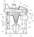
도 6은 도 3의 Ⅰ-Ⅰ'의 단면도로서, 도 6을 참조하여, 집진 유닛(400)의 내부 구성 및 집진유닛의 동작을 상세하게 설명한다.FIG. 6 is a cross-sectional view taken along line II ′ of FIG. 3 and with reference to FIG. 6, the internal structure of the
먼저, 상기 도 5에서 상세하게 설명된 바와 같이, 본 발명에 따른 집진유닛(400)에는, 집진바디(406)와, 상기 집진바디(406)의 하측을 선택적으로 밀폐시키는 실링부(402)(415)와, 상기 집진바디(406)의 내부에 수용되어 집진효율을 증대시키는 원추형 필터(405)와, 포집된 이물의 재비산을 막는 차단부(404)와, 싸이클론 유동의 유속이 저하되어 이물이 낙하되도록 하고, 먼지의 들뜸을 방지하는 유동방지판(403)과, 상기 집진바디(406)의 상측에 놓여서 상기 집진바디(406)로부터 배기되는 공기가 원활히 유동되도록 하는 배기부(407)와, 배기부(407)를 경유한 공기가 일방향으로 모이도록 하는 간격부(408)와, 상기 배기부(407)의 상측부에 놓이는 커버(409)(410)(411)(412)가 도시된다.First, as described in detail with reference to FIG. 5, in the
상기 집진바디(406)의 구성을 설명한다.The configuration of the
상기 집진바디(406)는 상하로 연장되는 복수개의 벽이 제공되는데, 최외각에 형성되는 외벽(418)과, 상기 외벽(418)의 안쪽에 형성되는 중간벽(419)과, 상기 중간벽(419)의 안쪽에 형성되는 내벽(420)이 포함된다. 그리고, 상기 중간벽(419) 및 내벽(420)은, 상기 집진유닛측 흡입구(401)가 통과되는 간격에는 형성되지 않도록 함으로써, 원활하게 공기가 유입되도록 한다.The
상기 외벽(418) 및 중간벽(419)의 사이 공간은 제 1 이물저장챔버(416)가 되고, 상기 중간벽(419)과 상기 내벽(420)의 사이 공간은 제 2 이물저장챔버(417)가 되고, 상기 내벽(420)의 내부 공간은 제 1 이물분리챔버(423)가 된다. 다만, 구체적으로 집진유닛(400)의 형태에 따라서, 공간의 사용상의 목적은 달라질 수 있을 것이다.The space between the
상기되는 구성에 의한 작용 내지 동작을 공기의 유동순서를 기준으로 상세하게 설명한다. 먼저, 상기 집진유닛측 흡입구(401)를 통하여 집진유닛(400)의 내부로 유입된다. 여기서, 상기 집진유닛측 흡입구(401)는 외측으로는 상기 전방 서포터(170)와 접하고, 내측으로는 상기 제 1 이물분리챔버(423)와 연통되어 외기가 유입된다. 그리고, 상기 집진유닛측 흡입구(401)의 내측에는 공기의 유동방향을 상기 제 1 이물분리챔버(423)의 내주면 방향으로 안내하기 위하여, 제 1 유입 가이드(421)가 상기 내벽(420)에서 안쪽으로 돌출되어 있다.The operation or operation by the above-described configuration will be described in detail based on the flow order of air. First, the dust is introduced into the
상기 제 1 이물분리챔버(423)의 내부에서 공기가 싸이클론 유동하는 중에, 이물은 하방으로 낙하되고 깨끗한 공기는 원추형 필터(405)의 개공을 통과하여 상측방향으로 배출된다. 이와 같이 원추형 필터(405)가 적용되는 것은, 집진유닛측 흡입구(401)가 상측에 위치하기 때문에 원추형 필터(405)의 상측부에는 비교적 고속회전의 싸이클론 유동이 일어나고, 하측부에는 비교적 저속의 싸이클론 유동이 일어나기 때문이다. 즉, 고속의 싸이클론 유동에서는 이물이 외측으로 좀더 많이 치우쳐서 회전되지만, 저속의 싸이클론 유동에서는 이물질이 내측으로 좀더 많이 퍼진 상태이기 때문에, 이물이 걸러지도록 하기 위해서는, 필터 부재가 원추형으로 적용되는 것이 바람직하다.During the cyclone flow of air in the first foreign
상기 원추형 필터(405)는 제 1 이물분리챔버(423)의 상면벽을 이루는 분리판(437)의 중심부에 안착되고, 상기 분리판(437)에서 선택적으로 분리가 가능한 구조로 제공될 수도 있다. 그리고, 상기 원추형 필터(405)에는 다수의 개공이 형성되어 공기가 외부에서 안쪽으로 통과하여 유입되는 것은 물론이다.The
여기서, 낙하된 이물의 재비산이 방지되기 위하여 상기 원추형 필터(405)의 하측에는 차단부(404)가 놓이고, 도시되는 바와 같이 상기 차단부(404)는 하방으로 갈수록 지름이 확장됨으로써, 이물의 상승이 차단되어 들뜨지 않도록 한다. 또한, 상기 차단부(404)의 하방에는 유동방지판(403)이 일정간격으로 형성되어, 일단 포집된 이물에 대해서는 싸이클론 공기 유동이 도달되지 않도록 함으로써, 이물이 들뜨는 현상이 원천적으로 없어지도록 한다.Here, the blocking
또한, 상기 제 1 이물분리챔버(423)의 내부에서 걸러진 이물은 하방의 제 1 이물저장챔버(416)에 저장된다. 여기서, 저장된 이물의 누설이 방지되도록 하기 위하여, 상기 제 1 이물저장챔버(416)의 하단부에는 제 1 챔버실링부(415)가 놓인다.In addition, the foreign material filtered in the first foreign
한편, 상기 원추형 필터(405)를 통과하여 분리판(437)의 상측으로 유입된 공기는 대략적으로 큰 이물은 걸러진 상태이다. 그러므로, 이차적으로 미세한 이물이 걸러지도록 하는 싸이클론 유동이 더 필요하게 된다. 이하에서는 더 수행되는 싸이클론 유동에 대해서 상세하게 설명한다.On the other hand, the air flowing through the
상기 원추형 필터(405)를 통과한 공기는 제 2 유입가이드(422)를 통하여 복수개의 제 2 이물분리챔버(424)의 내부로 유입된다. 또한, 상기 제 2 유입가이드(422)는 상기 제 2 이물분리챔버(424)의 내주면을 접선방향으로 향하도록 하기 때문에, 제 2 이물분리챔버(424)의 내부로 유입되는 공기는 챔버의 내부에 서 싸이클론 유동이 일어난다.Air passing through the
상기 제 2 이물분리챔버(424)의 내부에서 싸이클론 유동에 의해서 분리되는 이물은 하방으로 낙하되어 제 2 이물저장챔버(417)에 저장된다. 그리고, 낙하된 이물이 다시금 비산되지 않도록 하기 위하여, 상기 제 2 이물분리챔버(424)의 하측부는 수축되어 있다. 그리고, 상기 제 2 이물저장챔버(417)의 내부에 포집되는 이물이 누설되지 않도록 하기 위하여, 상기 제 2 이물저장챔버(417)의 하측부는 제 2 챔버실링부(402)에 의해서 밀폐된다.The foreign matter separated by the cyclone flow in the second foreign
여기서, 상기 제 2 챔버실링부(402)는 바 형태의 연결구조에 의해서 상기 제 1 챔버실링부(415)와 결합되어 있다. 이와 같이, 상기 제 1 챔버실링부(415)와 제 2 챔버실링부(402)가 바 형태의 연결구조에 의해서 연결되는 것은, 상기 제 1 이물저장챔버(416)의 내부용적을 크게 하기 위한 것이다. 다시 말하면, 상기 제 2 챔버실링부(402)의 하단에서 제 1 챔버실링부(415) 상단까지의 이격되는 공간에는 이물이 저장되기 때문에, 이물이 보다 많이 수용되도록 하기 위해서는 바 형태와 같은 작은 공간을 차지하는 부재에 의해서 연결되는 것이 바람직한 것이다.Here, the second
상기 제 2 이물분리챔버(424)의 내부에서 이물이 걸러진 뒤에는 배기부측 흡입구(425)를 경유하여 배기부(407)로 유입되어, 상기 배기부(407)와 간격부(408)의 사이간격의 공간에 모인다. 여기서, 상기 배기부측 흡입구(425)의 직경은 상기 제 2 이물분리챔버(424)의 내경보다 축소되는데, 이와 같은 직경의 관계로 인하여 제 2 이물분리챔버(424)의 이물이 상기 배기부(407)로 함께 유동하는 가능성은 더욱 줄어드는 장점을 얻을 수 있다. 다시 말하면, 제 2 이물분리챔버(424)의 내주면에 모여있는 이물은 상기 배기부측 흡입구(425)를 통하여 유출되지 않도록 하는 것이다.After the foreign material is filtered in the second foreign
설명된 바와 같이, 두 군데의 싸이클론 유동에 의해서 이물이 걸러진 공기는, 상기 모터측 흡입구(172)로 유입되어 모터로 유입된다. 그리고, 모터를 통과한 뒤에는 진공 청소기 본체(100)의 후면으로 배기된다.As described, the air filtered by foreign matter by two cyclone flows is introduced into the
또한, 상기 간격부(408)의 상측부에는 소정의 커버구조가 더 형성된다. 상세하게는, 전체적인 커버구조를 이루는 제 1 커버(410)와, 상기 제 1 커버(410)의 전방 및 후방을 보호하는 제 3 커버(412) 및 제 2 커버(409)와, 상기 제 1 커버(410)에 상기 제 2 커버(409)가 고정되도록 하는 커버 삽지구(411)가 제공된다.In addition, a predetermined cover structure is further formed on the upper portion of the
한편, 본 발명은 상기 집진바디(406)가 단일의 몸체로서, 단일의 사출과정으로 제조되는 것을 일 특징으로 하고 있는데, 이하에서는 상기 집진바디의 구성에 대해서 상세하게 설명한다.On the other hand, the present invention is characterized in that the
도 7은 본 발명에 따른 집진유닛에서 집진바디의 평면도이다. 도 5 및 도 7을 참조하면, 상기 집진바디(406)는 전체가 대략 원통형으로서, 상기 제 1 저장챔버(416), 제 2 저장챔버(417), 제 1 분리챔버(423), 제 2 분리챔버(424) 및 상기 분리판(437)이 일체로 제작된다. 그리고, 상기 제 1 저장챔버(416)의 외측 경계를 이루는 상기 외벽(418)과, 상기 제 2 저장챔버(417)의 간격부에서 적어도 한 곳에는 에지부(462)가 형성되어 있다.7 is a plan view of a dust collecting body in the dust collecting unit according to the present invention. 5 and 7, the
상기 에지부(462)는 상기 제 1 저장챔버(416)의 내부에서 회전되는 공기의 유동에서 와류가 발생되도록 함으로써, 상기 에지부(462)에 이물이 모이도록 하는 역할이 수행된다. 그리고, 상기 외벽(418)과 상기 제 2 저장챔버(417)의 간격이 일정정도 이상 떨어지도록 함으로써, 상기 집진바디(406)의 사출에 사용되는 금형이 일정정도 이상의 두께로 제조되어, 금형의 안정성을 높아지도록 한다.The
도 8은 본 발명에 따른 집진유닛에서 집진바디의 수직 단면도이다.8 is a vertical cross-sectional view of the dust collecting body in the dust collecting unit according to the present invention.
도 8을 참조하면, 상기 집진바디(406)는 상기 분리판(437)을 기준으로 하측에 제공되는 제 1 분리챔버(423)와, 상기 분리판(437)에서 상측으로 연장되는 관형상의 제 2 분리챔버(424)가 일체로 사출 성형된다. 그리고, 상기 분리판(437)에서 하측으로 연장되는 관 형상의 제 2 저장챔버(417)와, 상기 분리판(437)의 외주에서 하측방향으로 연장되는 외벽(418)의 내부 공간에 형성되는 제 1 저장챔버(416)가 일체로 사출성형된다.Referring to FIG. 8, the
다른 측면에서는, 상기 제 2 저장챔버(417)는 내벽(420)과 중간벽(419)의 내부 공간으로 형성되고, 상기 제 1 저장챔버(416)는 상기 외벽(418)의 내부공간으로 형성된다. 또한, 상기 제 2 분리챔버(423)는 상기 분리판(437)의 상측방향으로 연장되는 제 2 분리챔버벽(461)의 내부공간으로 결정된다.In another aspect, the
한편, 설명되는 바와 같이 상기 집진바디(406)가 일체형으로서 사출 성형되기 위해서는, 금형에 의한 사출 공정이 원활히 진행되어야 한다. 상세하게, 상기 분리판(437)을 기준으로 상측 부분은 상방으로 빠지는 금형에 의해서 제조가 수행되고, 상기 분리판(437)을 기준으로 하측 부분은 하방으로 빠지는 금형에 의해서 제조가 수행된다.On the other hand, as described above, in order for the
그러므로, 상기 분리챔버벽(461)과, 내벽(420)과, 중간벽(419)과, 외벽(418) 은 기저부분에서 그 단부로 갈수록 테이퍼지게 형성되어야 한다.Therefore, the
다시 말하면, 사출이 완료된 뒤에 금형이 빠질 때, 사출된 집진바디(406)의 몸체부분과 금형간의 간섭을 방지하기 위하여 내벽(420) 및 중간벽(419)의 기저부분의 두께(t2)는 단부의 두께(t1)에 비하여 두껍다. 이와 마찬가지로, 상기 제 2 분리챔버벽(461)의 기저부분의 두께(t3) 및 외벽(418)의 기저부분의 두께(t6)는 각각 단부의 두께(t4)(t5)에 비하여 두껍게 성형되어야 한다.In other words, when the mold is removed after the injection is completed, the thickness t2 of the base portion of the
다만, 상기 제 2 분리챔버(461) 하측부의 오므라드는 개구부는 그 자체가 테이퍼지기 때문에, 별도의 두께 변화를 줄 필요가 없다.However, since the opening of the omerad of the lower portion of the
설명된 바와 같이 본 발명에 제시되는 집진유닛(400)의 집진바디(406)는 일체형으로 제조되면서 그에 상응한 형상으로 제조된다.As described, the
상기되는 집진유닛(400)의 동작과 함께 진공 청소기 본체(100)의 전체적인 동작 내지 작용을 도 9에 제시되는 진공 청소기의 세로 단면도를 참조하여 상세하게 설명한다.The overall operation to the operation of the
도 9를 참조하면, 외기는 커넥터(6)와 연결되는 본체측 흡입구(171)를 통하여 진공 청소기 본체(100)로 유입되고, 집진유닛측 흡입구(401)를 통하여 집진유닛(400)의 내부로 유입된다. 그리고, 집진유닛(400)의 내부에서는 이미 설명된 바와 같은 동작 및 작용에 의해서 이물이 걸러진 뒤에, 모터측 흡입구(172)를 통하여 모터 하우징(300)의 내부로 유입된다.Referring to FIG. 9, the outside air flows into the vacuum cleaner
이때, 상기 모터 하우징(300)은 수직방향으로 세워진 상태에서 유입구는 상방을 향하고 있다. 그러므로, 상기 집진유닛(400)을 통과하여 수평으로 유입된 공 기는 진행방향이 꺾여서 하방으로 향하게 된다. 그리고, 상기 모터 하우징(300)을 통과한 뒤에는, 진공 청소기 본체(100)의 배면에 제공되는 본체 배기구(302)를 통하여 외부로 배출된다.At this time, the inlet is directed upward in the state in which the
본 발명은 상술되는 바와 같은 실시예에 제한되지 아니하며, 본 발명의 사상을 이해하는 당업자는 동일한 사상의 범위 내에서 다른 실시예를 용이하게 제안할 수 있을 것이다. 그러한 이러한 실시예도 본 발명 사상의 범위 내에 포함된다고 할 것이다.The present invention is not limited to the embodiments as described above, and those skilled in the art will be able to easily propose other embodiments within the scope of the same idea. Such embodiments will also be included within the scope of the invention.
설명되는 바와 같이 본 발명에 따른 진공 청소기의 집진유닛은 다수의 부품이 소수의 일체형 부품으로 간단하게 제작됨으로써, 제조과정이 단순화되기 때문에, 제조경비 및 제조시간이 절감되는 효과를 얻을 수 있다.As will be described, the dust collecting unit of the vacuum cleaner according to the present invention can be produced by simplifying the manufacturing process by simplifying the manufacturing process of a plurality of parts of a few integral parts, it is possible to obtain the effect of reducing the manufacturing cost and manufacturing time.
또한, 본 발명에 따른 집진유닛은 복수개의 물품 부분이 단일의 사출과정으로 일체로 제조되기 때문에, 제품의 정밀도가 향상되는 장점을 얻을 수 있다.In addition, the dust collecting unit according to the present invention can obtain the advantage that the accuracy of the product is improved because a plurality of article parts are integrally manufactured in a single injection process.
Claims (8)
Translated fromKoreanPriority Applications (6)
| Application Number | Priority Date | Filing Date | Title |
|---|---|---|---|
| KR1020040113377AKR100569330B1 (en) | 2004-12-27 | 2004-12-27 | Dust collection unit of vacuum cleaner |
| US11/232,859US7488363B2 (en) | 2004-12-27 | 2005-09-23 | Dust collection unit of vacuum cleaner |
| DE602005011746TDE602005011746D1 (en) | 2004-12-27 | 2005-10-04 | Multicyclone dust collector and vacuum cleaner with the same |
| AT05109186TATE417539T1 (en) | 2004-12-27 | 2005-10-04 | MULTI-CYCLONE DUST COLLECTOR AND VACUUM CLEANER WITH THE SAME |
| EP05109186AEP1674023B1 (en) | 2004-12-27 | 2005-10-04 | Multi-cyclone dust collecting unit and vacuum cleaner comprising same |
| RU2005140672/12ARU2314010C2 (en) | 2004-12-27 | 2005-12-26 | Dust collector device of vacuum cleaner |
Applications Claiming Priority (1)
| Application Number | Priority Date | Filing Date | Title |
|---|---|---|---|
| KR1020040113377AKR100569330B1 (en) | 2004-12-27 | 2004-12-27 | Dust collection unit of vacuum cleaner |
Publications (1)
| Publication Number | Publication Date |
|---|---|
| KR100569330B1true KR100569330B1 (en) | 2006-04-07 |
Family
ID=35788228
Family Applications (1)
| Application Number | Title | Priority Date | Filing Date |
|---|---|---|---|
| KR1020040113377AExpired - Fee RelatedKR100569330B1 (en) | 2004-12-27 | 2004-12-27 | Dust collection unit of vacuum cleaner |
Country Status (6)
| Country | Link |
|---|---|
| US (1) | US7488363B2 (en) |
| EP (1) | EP1674023B1 (en) |
| KR (1) | KR100569330B1 (en) |
| AT (1) | ATE417539T1 (en) |
| DE (1) | DE602005011746D1 (en) |
| RU (1) | RU2314010C2 (en) |
Cited By (2)
| Publication number | Priority date | Publication date | Assignee | Title |
|---|---|---|---|---|
| WO2007149254A3 (en)* | 2006-06-16 | 2008-04-03 | Royal Appliance Mfg | Separately opening dust containers of a domestic cyclonic suction cleaner |
| CN103040417A (en)* | 2012-12-20 | 2013-04-17 | 大连民族学院 | Gas-dust separation device with double-layer whirlwind track |
Families Citing this family (61)
| Publication number | Priority date | Publication date | Assignee | Title |
|---|---|---|---|---|
| US20070209334A1 (en)* | 2006-03-10 | 2007-09-13 | Gbd Corp. | Vacuum cleaner with a removable screen |
| US9301666B2 (en) | 2006-12-12 | 2016-04-05 | Omachron Intellectual Property Inc. | Surface cleaning apparatus |
| CA2599303A1 (en) | 2007-08-29 | 2009-02-28 | Gbd Corp. | Surface cleaning apparatus |
| US8146201B2 (en)* | 2006-12-12 | 2012-04-03 | G.B.D. Corp. | Surface cleaning apparatus |
| US12220099B2 (en) | 2006-12-12 | 2025-02-11 | Omachron Intellectual Property Inc. | Surface cleaning apparatus |
| US9192269B2 (en) | 2006-12-15 | 2015-11-24 | Omachron Intellectual Property Inc. | Surface cleaning apparatus |
| US7867308B2 (en)* | 2006-12-15 | 2011-01-11 | G.B.D. Corp. | Cyclonic array such as for a vacuum cleaner |
| US10165912B2 (en) | 2006-12-15 | 2019-01-01 | Omachron Intellectual Property Inc. | Surface cleaning apparatus |
| US11857142B2 (en) | 2006-12-15 | 2024-01-02 | Omachron Intellectual Property Inc. | Surface cleaning apparatus having an energy storage member and a charger for an energy storage member |
| US20210401246A1 (en) | 2016-04-11 | 2021-12-30 | Omachron Intellectual Property Inc. | Surface cleaning apparatus |
| US20080172992A1 (en)* | 2006-12-15 | 2008-07-24 | G.B.D. Corp. | Vacuum cleaner with openable lid |
| US9888817B2 (en) | 2014-12-17 | 2018-02-13 | Omachron Intellectual Property Inc. | Surface cleaning apparatus |
| US12048409B2 (en) | 2007-03-11 | 2024-07-30 | Omachron Intellectual Property Inc. | Portable surface cleaning apparatus |
| US11751733B2 (en) | 2007-08-29 | 2023-09-12 | Omachron Intellectual Property Inc. | Portable surface cleaning apparatus |
| US12004700B2 (en) | 2007-08-29 | 2024-06-11 | Omachron Intellectual Property Inc. | Cyclonic surface cleaning apparatus |
| CA2967272C (en) | 2009-03-13 | 2018-01-02 | Omachron Intellectual Property Inc. | Hand vacuum cleaner |
| US11690489B2 (en) | 2009-03-13 | 2023-07-04 | Omachron Intellectual Property Inc. | Surface cleaning apparatus with an external dirt chamber |
| US9265395B2 (en) | 2010-03-12 | 2016-02-23 | Omachron Intellectual Property Inc. | Surface cleaning apparatus |
| US9211044B2 (en)* | 2011-03-04 | 2015-12-15 | Omachron Intellectual Property Inc. | Compact surface cleaning apparatus |
| US10722086B2 (en) | 2017-07-06 | 2020-07-28 | Omachron Intellectual Property Inc. | Handheld surface cleaning apparatus |
| US12156626B2 (en) | 2009-03-13 | 2024-12-03 | Omachron Intellectual Property Inc. | Surface cleaning apparatus |
| US9433332B2 (en) | 2013-02-27 | 2016-09-06 | Omachron Intellectual Property Inc. | Surface cleaning apparatus |
| US8640304B2 (en) | 2010-03-12 | 2014-02-04 | G.B.D. Corp. | Cyclone construction for a surface cleaning apparatus |
| US8978198B2 (en)* | 2011-03-03 | 2015-03-17 | G.B.D. Corp. | Filter housing for a surface cleaning apparatus |
| US9232881B2 (en) | 2011-03-04 | 2016-01-12 | Omachron Intellectual Property Inc. | Surface cleaning apparatus with removable handle assembly |
| JP2013236671A (en)* | 2012-05-11 | 2013-11-28 | Toshiba Corp | Electric vacuum cleaner |
| US9591958B2 (en) | 2013-02-27 | 2017-03-14 | Omachron Intellectual Property Inc. | Surface cleaning apparatus |
| US9027198B2 (en) | 2013-02-27 | 2015-05-12 | G.B.D. Corp. | Surface cleaning apparatus |
| US9320401B2 (en) | 2013-02-27 | 2016-04-26 | Omachron Intellectual Property Inc. | Surface cleaning apparatus |
| US9227151B2 (en) | 2013-02-28 | 2016-01-05 | Omachron Intellectual Property Inc. | Cyclone such as for use in a surface cleaning apparatus |
| US9820621B2 (en) | 2013-02-28 | 2017-11-21 | Omachron Intellectual Property Inc. | Surface cleaning apparatus |
| US9451855B2 (en) | 2013-02-28 | 2016-09-27 | Omachron Intellectual Property Inc. | Surface cleaning apparatus |
| US9238235B2 (en) | 2013-02-28 | 2016-01-19 | Omachron Intellectual Property Inc. | Cyclone such as for use in a surface cleaning apparatus |
| US9295995B2 (en) | 2013-02-28 | 2016-03-29 | Omachron Intellectual Property Inc. | Cyclone such as for use in a surface cleaning apparatus |
| US9227201B2 (en) | 2013-02-28 | 2016-01-05 | Omachron Intellectual Property Inc. | Cyclone such as for use in a surface cleaning apparatus |
| US9204773B2 (en) | 2013-03-01 | 2015-12-08 | Omachron Intellectual Property Inc. | Surface cleaning apparatus |
| US9161669B2 (en) | 2013-03-01 | 2015-10-20 | Omachron Intellectual Property Inc. | Surface cleaning apparatus |
| US20140237764A1 (en) | 2013-02-28 | 2014-08-28 | G.B.D. Corp. | Cyclone such as for use in a surface cleaning apparatus |
| US9427126B2 (en) | 2013-03-01 | 2016-08-30 | Omachron Intellectual Property Inc. | Surface cleaning apparatus |
| US9326652B2 (en) | 2013-02-28 | 2016-05-03 | Omachron Intellectual Property Inc. | Surface cleaning apparatus |
| US9451853B2 (en) | 2014-07-18 | 2016-09-27 | Omachron Intellectual Property Inc. | Portable surface cleaning apparatus |
| US9420925B2 (en) | 2014-07-18 | 2016-08-23 | Omachron Intellectual Property Inc. | Portable surface cleaning apparatus |
| US9314139B2 (en) | 2014-07-18 | 2016-04-19 | Omachron Intellectual Property Inc. | Portable surface cleaning apparatus |
| US9585530B2 (en) | 2014-07-18 | 2017-03-07 | Omachron Intellectual Property Inc. | Portable surface cleaning apparatus |
| US10251519B2 (en) | 2014-12-17 | 2019-04-09 | Omachron Intellectual Property Inc. | Surface cleaning apparatus |
| US10136778B2 (en) | 2014-12-17 | 2018-11-27 | Omachron Intellectual Property Inc. | Surface cleaning apparatus |
| US11950745B2 (en) | 2014-12-17 | 2024-04-09 | Omachron Intellectual Property Inc. | Surface cleaning apparatus |
| US10842330B2 (en) | 2017-07-06 | 2020-11-24 | Omachron Intellectual Property Inc. | Handheld surface cleaning apparatus |
| US11766156B2 (en) | 2020-03-18 | 2023-09-26 | Omachron Intellectual Property Inc. | Surface cleaning apparatus with removable air treatment member assembly |
| US10702113B2 (en) | 2017-07-06 | 2020-07-07 | Omachron Intellectual Property Inc. | Handheld surface cleaning apparatus |
| US11666193B2 (en) | 2020-03-18 | 2023-06-06 | Omachron Intellectual Property Inc. | Surface cleaning apparatus with removable air treatment member assembly |
| US10631693B2 (en) | 2017-07-06 | 2020-04-28 | Omachron Intellectual Property Inc. | Handheld surface cleaning apparatus |
| US11730327B2 (en) | 2020-03-18 | 2023-08-22 | Omachron Intellectual Property Inc. | Surface cleaning apparatus with removable air treatment assembly |
| US10750913B2 (en) | 2017-07-06 | 2020-08-25 | Omachron Intellectual Property Inc. | Handheld surface cleaning apparatus |
| US10506904B2 (en) | 2017-07-06 | 2019-12-17 | Omachron Intellectual Property Inc. | Handheld surface cleaning apparatus |
| US11445878B2 (en) | 2020-03-18 | 2022-09-20 | Omachron Intellectual Property Inc. | Surface cleaning apparatus with removable air treatment member assembly |
| US10537216B2 (en) | 2017-07-06 | 2020-01-21 | Omachron Intellectual Property Inc. | Handheld surface cleaning apparatus |
| US11930987B2 (en) | 2018-04-20 | 2024-03-19 | Omachron Intellectual Property Inc. | Surface cleaning apparatus |
| US11192122B2 (en) | 2018-08-13 | 2021-12-07 | Omachron Intellectual Property Inc. | Cyclonic air treatment member and surface cleaning apparatus including the same |
| US11013384B2 (en) | 2018-08-13 | 2021-05-25 | Omachron Intellectual Property Inc. | Cyclonic air treatment member and surface cleaning apparatus including the same |
| US11006799B2 (en) | 2018-08-13 | 2021-05-18 | Omachron Intellectual Property Inc. | Cyclonic air treatment member and surface cleaning apparatus including the same |
Family Cites Families (13)
| Publication number | Priority date | Publication date | Assignee | Title |
|---|---|---|---|---|
| JPS5547496B2 (en) | 1974-01-05 | 1980-12-01 | ||
| EP0042723B1 (en)* | 1980-06-19 | 1985-08-21 | Rotork Appliances Limited | Vacuum cleaning appliance |
| US5893938A (en)* | 1995-12-20 | 1999-04-13 | Notetry Limited | Dust separation apparatus |
| GB2326360A (en) | 1997-06-16 | 1998-12-23 | Notetry Ltd | cyclonic separating apparatus |
| DE19911226A1 (en) | 1999-03-13 | 2000-09-14 | Josef Kraenzle | Vacuum cleaner for cleaning purposes |
| RU2236813C2 (en) | 2000-02-19 | 2004-09-27 | Эл Джи Электроникс Инк. | Multi-cyclone vacuum cleaner |
| GB2360719B (en)* | 2000-03-31 | 2003-04-30 | Notetry Ltd | A domestic vacuum cleaner for separating particles from a fluid flow |
| CN2453827Y (en) | 2000-12-27 | 2001-10-17 | 倪祖根 | Split wirlwind dust-filtering device of cleaner |
| JP3659191B2 (en) | 2001-05-08 | 2005-06-15 | 松下電器産業株式会社 | Centrifugal dust collector and electric vacuum cleaner using the same |
| KR100444323B1 (en) | 2001-10-05 | 2004-08-16 | 삼성광주전자 주식회사 | Grille assembly for a cyclone-type dust collecting apparatus for a vacuum cleaner |
| ATE455489T1 (en) | 2001-10-12 | 2010-02-15 | Arcelik As | VACUUM CLEANER |
| GB2399780A (en) | 2003-03-28 | 2004-09-29 | Dyson Ltd | Arrangement of cyclones for noise damping |
| KR100536503B1 (en)* | 2003-09-09 | 2005-12-14 | 삼성광주전자 주식회사 | A cyclone separating apparatus and vacumm cleaner equipped whth such a device |
- 2004
- 2004-12-27KRKR1020040113377Apatent/KR100569330B1/ennot_activeExpired - Fee Related
- 2005
- 2005-09-23USUS11/232,859patent/US7488363B2/ennot_activeExpired - Fee Related
- 2005-10-04ATAT05109186Tpatent/ATE417539T1/ennot_activeIP Right Cessation
- 2005-10-04EPEP05109186Apatent/EP1674023B1/ennot_activeExpired - Lifetime
- 2005-10-04DEDE602005011746Tpatent/DE602005011746D1/ennot_activeExpired - Lifetime
- 2005-12-26RURU2005140672/12Apatent/RU2314010C2/ennot_activeIP Right Cessation
Cited By (5)
| Publication number | Priority date | Publication date | Assignee | Title |
|---|---|---|---|---|
| WO2007149254A3 (en)* | 2006-06-16 | 2008-04-03 | Royal Appliance Mfg | Separately opening dust containers of a domestic cyclonic suction cleaner |
| GB2452891A (en)* | 2006-06-16 | 2009-03-18 | Royal Appliance Mfg | Separately opening dust containers of a domestic cyclonic suction cleaner |
| US7604675B2 (en) | 2006-06-16 | 2009-10-20 | Royal Appliance Mfg. Co. | Separately opening dust containers |
| GB2452891B (en)* | 2006-06-16 | 2011-10-19 | Royal Appliance Mfg | Separately opening dust containers of a domestic cyclonic suction cleaner |
| CN103040417A (en)* | 2012-12-20 | 2013-04-17 | 大连民族学院 | Gas-dust separation device with double-layer whirlwind track |
Also Published As
| Publication number | Publication date |
|---|---|
| US7488363B2 (en) | 2009-02-10 |
| RU2005140672A (en) | 2007-07-10 |
| EP1674023A1 (en) | 2006-06-28 |
| EP1674023B1 (en) | 2008-12-17 |
| ATE417539T1 (en) | 2009-01-15 |
| RU2314010C2 (en) | 2008-01-10 |
| DE602005011746D1 (en) | 2009-01-29 |
| US20060137307A1 (en) | 2006-06-29 |
Similar Documents
| Publication | Publication Date | Title |
|---|---|---|
| KR100569330B1 (en) | Dust collection unit of vacuum cleaner | |
| KR100697429B1 (en) | Vacuum cleaner | |
| KR100633605B1 (en) | Dust collection unit of vacuum cleaner | |
| KR100553042B1 (en) | Dust collection unit of vacuum cleaner | |
| KR100706622B1 (en) | Compact Dual Cyclone Dust Collector for Vacuum Cleaners | |
| US7501002B2 (en) | Cyclone dust separator and a vacuum cleaner having the same | |
| US9125534B2 (en) | Vacuum cleaner | |
| EP2702914B1 (en) | Vacuum cleaner | |
| KR100677982B1 (en) | Motor filter seating structure of vacuum cleaner | |
| KR100575319B1 (en) | Dust collection unit of vacuum cleaner | |
| KR20060086088A (en) | Dust collection unit of vacuum cleaner | |
| KR100548933B1 (en) | Suction structure of vacuum cleaner | |
| KR100553043B1 (en) | Dust collection unit of vacuum cleaner | |
| KR100697428B1 (en) | Damper mounting structure of vacuum cleaner | |
| KR100676531B1 (en) | Dust collection unit switchgear of vacuum cleaner | |
| KR100676533B1 (en) | Euro structure of vacuum cleaner | |
| KR100596250B1 (en) | Foreign body discharge structure of vacuum cleaner | |
| KR100564443B1 (en) | Dust collector of vacuum cleaner and vacuum cleaner | |
| KR100569351B1 (en) | Nozzle Parking Structure of Vacuum Cleaner | |
| KR100553044B1 (en) | Dust collection unit of vacuum cleaner | |
| KR100676532B1 (en) | Cover structure of dust collection unit | |
| KR100709403B1 (en) | Handle structure of vacuum cleaner | |
| KR100596252B1 (en) | Dust collection unit of vacuum cleaner | |
| KR100676528B1 (en) | Dust collection unit mounting structure of vacuum cleaner | |
| KR100596251B1 (en) | Dust collection unit of vacuum cleaner |
Legal Events
| Date | Code | Title | Description |
|---|---|---|---|
| PA0109 | Patent application | St.27 status event code:A-0-1-A10-A12-nap-PA0109 | |
| A201 | Request for examination | ||
| PA0201 | Request for examination | St.27 status event code:A-1-2-D10-D11-exm-PA0201 | |
| A302 | Request for accelerated examination | ||
| PA0302 | Request for accelerated examination | St.27 status event code:A-1-2-D10-D17-exm-PA0302 St.27 status event code:A-1-2-D10-D16-exm-PA0302 | |
| E902 | Notification of reason for refusal | ||
| PE0902 | Notice of grounds for rejection | St.27 status event code:A-1-2-D10-D21-exm-PE0902 | |
| T11-X000 | Administrative time limit extension requested | St.27 status event code:U-3-3-T10-T11-oth-X000 | |
| E13-X000 | Pre-grant limitation requested | St.27 status event code:A-2-3-E10-E13-lim-X000 | |
| P11-X000 | Amendment of application requested | St.27 status event code:A-2-2-P10-P11-nap-X000 | |
| P13-X000 | Application amended | St.27 status event code:A-2-2-P10-P13-nap-X000 | |
| E701 | Decision to grant or registration of patent right | ||
| PE0701 | Decision of registration | St.27 status event code:A-1-2-D10-D22-exm-PE0701 | |
| PR1002 | Payment of registration fee | St.27 status event code:A-2-2-U10-U11-oth-PR1002 Fee payment year number:1 | |
| GRNT | Written decision to grant | ||
| PR0701 | Registration of establishment | St.27 status event code:A-2-4-F10-F11-exm-PR0701 | |
| PG1601 | Publication of registration | St.27 status event code:A-4-4-Q10-Q13-nap-PG1601 | |
| PN2301 | Change of applicant | St.27 status event code:A-5-5-R10-R13-asn-PN2301 St.27 status event code:A-5-5-R10-R11-asn-PN2301 | |
| LAPS | Lapse due to unpaid annual fee | ||
| PC1903 | Unpaid annual fee | St.27 status event code:A-4-4-U10-U13-oth-PC1903 Not in force date:20090404 Payment event data comment text:Termination Category : DEFAULT_OF_REGISTRATION_FEE | |
| R18-X000 | Changes to party contact information recorded | St.27 status event code:A-5-5-R10-R18-oth-X000 | |
| R18-X000 | Changes to party contact information recorded | St.27 status event code:A-5-5-R10-R18-oth-X000 | |
| PC1903 | Unpaid annual fee | St.27 status event code:N-4-6-H10-H13-oth-PC1903 Ip right cessation event data comment text:Termination Category : DEFAULT_OF_REGISTRATION_FEE Not in force date:20090404 | |
| PN2301 | Change of applicant | St.27 status event code:A-5-5-R10-R13-asn-PN2301 St.27 status event code:A-5-5-R10-R11-asn-PN2301 | |
| PN2301 | Change of applicant | St.27 status event code:A-5-5-R10-R13-asn-PN2301 St.27 status event code:A-5-5-R10-R11-asn-PN2301 |