KR100566737B1 - Hybrid Parallel / Serial Bus Interface - Google Patents
Hybrid Parallel / Serial Bus InterfaceDownload PDFInfo
- Publication number
- KR100566737B1 KR100566737B1KR1020047007785AKR20047007785AKR100566737B1KR 100566737 B1KR100566737 B1KR 100566737B1KR 1020047007785 AKR1020047007785 AKR 1020047007785AKR 20047007785 AKR20047007785 AKR 20047007785AKR 100566737 B1KR100566737 B1KR 100566737B1
- Authority
- KR
- South Korea
- Prior art keywords
- data
- data block
- bits
- serial
- nibble
- Prior art date
- Legal status (The legal status is an assumption and is not a legal conclusion. Google has not performed a legal analysis and makes no representation as to the accuracy of the status listed.)
- Expired - Fee Related
Links
Images


Classifications
- H—ELECTRICITY
- H04—ELECTRIC COMMUNICATION TECHNIQUE
- H04L—TRANSMISSION OF DIGITAL INFORMATION, e.g. TELEGRAPHIC COMMUNICATION
- H04L5/00—Arrangements affording multiple use of the transmission path
- H04L5/20—Arrangements affording multiple use of the transmission path using different combinations of lines, e.g. phantom working
- H—ELECTRICITY
- H04—ELECTRIC COMMUNICATION TECHNIQUE
- H04L—TRANSMISSION OF DIGITAL INFORMATION, e.g. TELEGRAPHIC COMMUNICATION
- H04L25/00—Baseband systems
- H04L25/02—Details ; arrangements for supplying electrical power along data transmission lines
- H04L25/14—Channel dividing arrangements, i.e. in which a single bit stream is divided between several baseband channels and reassembled at the receiver
- H—ELECTRICITY
- H03—ELECTRONIC CIRCUITRY
- H03M—CODING; DECODING; CODE CONVERSION IN GENERAL
- H03M9/00—Parallel/series conversion or vice versa
Landscapes
- Engineering & Computer Science (AREA)
- Signal Processing (AREA)
- Computer Networks & Wireless Communication (AREA)
- Theoretical Computer Science (AREA)
- Power Engineering (AREA)
- Information Transfer Systems (AREA)
- Communication Control (AREA)
- Time-Division Multiplex Systems (AREA)
- Dc Digital Transmission (AREA)
- Mobile Radio Communication Systems (AREA)
- Small-Scale Networks (AREA)
Abstract
Translated fromKoreanDescription
Translated fromKorean본 발명은 버스 데이터 전송들에 관한 것이다. 특히, 본 발명은 버스 데이터를 전송하는 라인들의 수를 감소시키는 것에 관한 것이다.The present invention relates to bus data transmissions. In particular, the invention relates to reducing the number of lines transmitting bus data.
데이터를 전송하는데 사용되는 버스의 일 예는 도 1에 도시되어 있다. 도 1은 무선 통신 시스템에서 사용하는 수신 및 송신 이득 제어기들(GCs; gain controllers)(30, 32) 및 GC 제어기(38)의 예시이다. 기지국(base station) 또는 사용자 장치(user equipment)와 같은 통신국은 신호들을 송신(TX)하고 수신(RX)한다. 다른 수신/송신 구성요소들의 동작 범위내에 있는 이들 신호들의 이득을 제어하기 위하여, 이 GC들(30, 32)은 RX 및 TX 신호들에 대한 이득을 조절한다.One example of a bus used to transfer data is shown in FIG. 1 is an illustration of receive and transmit gain controllers (GCs) 30 and 32 and a
GC들(30, 32)의 이득 파라미터들을 제어하기 위하여, GC 제어기(38)가 사용된다. 도 1에 도시된 바와 같이, GC 제어기(38)는 각각에 대해 8개의 라인들과 같은 TX(36) 및 RX(34) 신호들에 대한 이득 값을 전송하기 위하여, 16개의 라인 버스(34, 36)와 같은 파워 제어 버스를 사용한다. 비록 파워 제어 버스 라인들(34, 36)은 빠른 데이터 전송을 허용한다고 하더라도, 이것은 GC들(30, 32) 및 GC 제어기(38)상의 많은 핀들 또는 ASIC(Application Specific IC)와 같은 집적회로(IC)상 의 GC들(30, 32) 및 GC 제어기(38) 간에 많은 접속들을 요구한다. 핀들의 수를 증가시키는 것은 추가적인 회로 기판 공간 및 접속들을 요구한다. IC 접속들을 증가시키는 것은 귀중한 IC 공간을 사용한다. 많은 수의 핀들 또는 접속들은 그 구현에 따른 버스의 비용을 증가시킬 수 있다.In order to control the gain parameters of the
따라서, 다른 데이터 전송 접근법들을 갖는 것이 바람직하다.Therefore, it is desirable to have other data transfer approaches.
하이브리드 직렬/병렬 버스 인터페이스는 데이터 블록 디멀티플렉싱 디바이스를 갖는다. 이 데이터 블록 디멀티플렉싱 디바이스는 데이터 블록을 수신하도록 구성된 입력을 갖고, 복수의 니블들로 그 데이터 블록을 디멀티플렉싱한다. 각각의 니블에 대해, 병렬-직렬 변환기는 그 니블을 직렬 데이터로 변환시킨다. 라인은 각각의 니블의 직렬 데이터를 전송한다. 직렬-병렬 변환기는 그 니블을 복구하기 위해 각각의 니블의 직렬 데이터를 변환한다. 데이터 블록 재구성 디바이스는 그 복구된 니블들을 데이터 블록으로 결합한다.The hybrid serial / parallel bus interface has a data block demultiplexing device. This data block demultiplexing device has an input configured to receive a data block and demultiplexes the data block into a plurality of nibbles. For each nibble, the parallel-to-serial converter converts the nibble to serial data. The line carries serial data for each nibble. The serial-to-parallel converter converts the serial data of each nibble to recover the nibble. The data block reconstruction device combines the recovered nibbles into a data block.
도 1은 RX 및 TX GC 및 GC 제어기의 예시이다.1 is an illustration of an RX and TX GC and GC controller.
도 2는 하이브리드 병렬/직렬 버스 인터페이스의 블록도이다.2 is a block diagram of a hybrid parallel / serial bus interface.
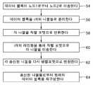
도 3은 하이브리드 병렬/직렬 버스 인터페이스를 사용하여 데이터 블록들을 전송하는 흐름도이다.3 is a flow diagram for transmitting data blocks using a hybrid parallel / serial bus interface.
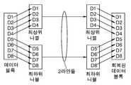
도 4는 블록을 최상위 및 최하위 니블로 디멀티플렉싱하는 것을 도시한다.4 illustrates demultiplexing a block with top and bottom nibbles.
도 5는 데이터 인터리빙을 사용하여 블록을 디멀티플렉싱하는 것을 도시한 다.5 illustrates demultiplexing a block using data interleaving.
도 6은 양방향 하이브리드 병렬/직렬 버스 인터페이스의 블록도이다.6 is a block diagram of a bidirectional hybrid parallel / serial bus interface.
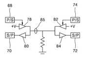
도 7은 하나의 양방향 라인의 구현을 나타내는 도면이다.7 illustrates an implementation of one bidirectional line.
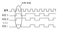
도 8은 시작 비트들을 나타내는 타이밍도이다.8 is a timing diagram illustrating start bits.
도 9는 기능 제어가능 하이브리드 병렬/직렬 버스 인터페이스의 블록도이다.9 is a block diagram of a function controllable hybrid parallel / serial bus interface.
도 10은 기능 제어가능 하이브리드 병렬/직렬 버스 인터페이스에서의 시작 비트들의 타이밍도이다.10 is a timing diagram of start bits in a function controllable hybrid parallel / serial bus interface.
도 11은 기능들을 나타내는 시작 비트들의 구현을 나타내는 표이다.11 is a table illustrating an implementation of start bits representing functions.
도 12는 목적지 제어 하이브리드 병렬/직렬 버스 인터페이스의 블록도이다.12 is a block diagram of a destination control hybrid parallel / serial bus interface.
도 13은 목적지들을 나타내는 시작 비트들의 구현을 나타내는 표이다.13 is a table showing an implementation of start bits representing destinations.
도 14는 목적지들/기능들을 나타내는 시작 비트들의 구현을 나타내는 표이다.14 is a table illustrating an implementation of start bits representing destinations / functions.
도 15는 목적지들/기능들을 제어하는 하이브리드 병렬/직렬 버스 인터페이스의 블록도이다.15 is a block diagram of a hybrid parallel / serial bus interface controlling destinations / functions.
도 16은 목적지들/기능들을 나타내는 시작 비트들에 대한 흐름도이다.16 is a flow diagram for start bits indicating destinations / functions.
도 17은 포지티브 및 네거티브 클록 에지 하이브리드 병렬/직렬 버스 인터페이스를 나타내는 블록도이다.17 is a block diagram illustrating a positive and negative clock edge hybrid parallel / serial bus interface.
도 18은 포지티브 및 네거티브 클록 에지 하이브리드 병렬/직렬 버스 인터페이스를 나타내는 타이밍도이다.18 is a timing diagram illustrating a positive and negative clock edge hybrid parallel / serial bus interface.
도 19는 2-라인 GC/GC 제어기 버스의 블록도이다.19 is a block diagram of a two-line GC / GC controller bus.
도 20은 3-라인 GC/GC 제어기 버스의 블록도이다.20 is a block diagram of a three-line GC / GC controller bus.
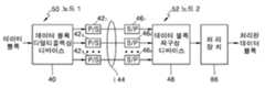
도 2는 하이브리드 병렬/직렬 버스 인터페이스의 블록도이고, 도 3은 하이브리드 병렬/직렬 버스 인터페이스 데이터 전송을 나타내는 흐름도이다. 데이터 블록은 노드 1(50)로부터 노드 2(52)로 인터페이스 i(44)를 통해 전송된다(54). 데이터 블록 디멀티플렉싱 디바이스(40)는 그 블록을 수신하고, 이것을 i개의 데이터 전송 라인들(44)상에서 전송하기 위해 i개의 니블(nibble)들로 디멀티플렉싱한다(56). i에 대한 값은 접속들의 수와 전송 속도 간의 트레이드오프(tradeoff)에 근거한다. i를 결정하는 하나의 접근은 우선 데이터 블록을 전송하는데 허용되는 최대 대기시간(latency)을 결정하는 것이다. 허용되는 최대 대기시간에 근거하여, 블록을 전송하는데 요구되는 라인들의 최소 수가 결정된다. 라인들의 최소 수를 이용하여, 데이터를 전송하는데 사용되는 라인들이 적어도 최소가 되도록 선택된다. 라인들(44)은 핀들 및 그들의 연관된 회로 기판상의 접속들 또는 IC상의 접속들일 수 있다. 니블들로 디멀티플렉싱하는 하나의 접근법은 블록을 최상위 내지 최하위 니블로 분할하는 것이다. 도 4에 도시된 바와 같이 2개의 라인들상에서 8 비트 블록 전송을 예시하기 위하여, 블록은 4 비트 최상위 니블 및 4 비트 최하위 니블로 디멀티플렉싱된다.2 is a block diagram of a hybrid parallel / serial bus interface, and FIG. 3 is a flowchart illustrating hybrid parallel / serial bus interface data transmission. The data block is sent (54) from interface 1 (44) to node 2 (52). The data
다른 하나의 접근법은 블록을 i개의 니블들을 통해 인터리빙하는 것이다. 블록의 제1 i 비트들은 각 니블의 제1 비트가 된다. 제2 i 비트들은 각 니블내의 제2 비트가 되고 최종 i 비트들까지 계속된다. 도 5에 도시된 바와 같이 2개의 접속들 상의 8 비트 블록을 예시하기 위하여, 제1 비트는 니블 1의 제1 비트에 매핑된다. 제2 비트는 니블 2의 제1 비트에 매핑된다. 제3 비트는 니블 1의 제2 비트에 매핑되고, 최종 비트가 니블 2의 최종 비트에 매핑될 때까지 계속된다.Another approach is to interleave the block through i nibbles. The first i bits of the block become the first bits of each nibble. The second i bits become the second bit in each nibble and continue until the last i bits. To illustrate an 8-bit block on two connections as shown in FIG. 5, the first bit is mapped to the first bit of
각 니블은 i개의 병렬-직렬(P/S; parallel to serial) 변환기들(42)중의 해당 변환기에 전송되고(58), 병렬 비트들로부터 직렬 비트들로 변환되며, 그 라인을 통해 순차적으로 전송된다(60). 각 라인의 반대쪽 단부에는 직렬-병렬(S/P; serial to parallel) 변환기(46)가 있다. 각 S/P 변환기(46)는 송신된 직렬 데이터를 원래의 니블로 변환한다(62). i개의 회복된 니블들은 원래의 데이터 블록을 재구성하기 위하여 데이터 블록 재구성 디바이스(48)에 의해 처리된다(64).Each nibble is transmitted 58 to the corresponding one of the i parallel to serial (P / S)
다른 하나의 양방향 접근법에 있어서, 도 6에 도시된 바와 같이 i개의 접속들이 양방향들로 데이터를 전송하는데 사용된다. 정보 데이터는 양방향으로 전송되거나 또는 정보가 한 방향으로 전송되고 승인이 다른 방향으로 돌려보내질 수 있다. 노드 1(50)로부터 노드 2(52)로의 전송을 위한 데이터 블록은 데이터 블록 디멀티플렉싱 및 재구성 디바이스(66)에 의해 수신된다. 디멀티플렉싱 및 재구성 디바이스(66)는 블록을 i개의 니블들로 디멀티플렉싱한다. i개의 P/S 변환기들(68)은 각 니블을 직렬 데이터로 변환한다. 한 세트의 멀티플렉서들(MUXs; multiplexers)/DEMUX들(71)은 각 P/S 변환기(68)를 i개의 라인들(44) 중의 대응하는 라인에 연결한다. 노드 2(52)에서, 다른 한 세트의 MUX들/DEMUX들(75)은 라인들(44)을 한 세트의 S/P 변환기들(72)에 접속한다. S/P 변환기들(72)은 각 니블의 수신된 직렬 데이터를 원래 송신된 니블들로 변환한다. 수신된 니블들은 데이 터 블록 디멀티플렉싱 및 재구성 디바이스(76)에 의해 원래 데이터 블록으로 재구성되고 수신된 데이터 블록으로서 출력된다.In another bi-directional approach, i connections are used to transmit data in both directions, as shown in FIG. The information data can be sent in both directions, or the information can be sent in one direction and the authorization returned in the other direction. The data block for transmission from
노드 2(52)로부터 노드 1(50)로 전송되는 블록들에서, 데이터 블록은 데이터 블록 디멀티플렉싱 및 재구성 디바이스(76)에 의해 수신된다. 블록은 니블들로 디멀티플렉싱되고 니블들은 한 세트의 P/S 변환기들(74)로 전송된다. P/S 변환기들(74)은 각 니블을 i개의 라인들(44)을 통해 전송하기 위해 직렬 포맷으로 변환한다. 노드 2의 MUX들/DEMUX들 세트(75)는 P/S 변환기들(74)을 i개의 라인들(44)에 연결하고 노드 1의 MUX들/DEMUX들 세트(71)는 라인들(44)을 i개의 S/P 변환기들(70)에 연결한다. S/P 변환기들(70)은 송신된 데이터를 원래의 니블들로 변환한다. 데이터 블록 디멀티플렉싱 및 재구성 디바이스(66)는 수신된 데이터 블록을 출력하기 위하여 수신된 니블들로부터 데이터 블록을 재구성한다. 데이터는 한번에 한 방향으로만 전송되기 때문에, 이 구현은 반 이중 모드(half duplex mode)로 동작한다.In the blocks transmitted from
도 7은 양방향 스위칭 회로들의 일 구현예의 간략화된 도면이다. 노드 1의 P/S 변환기(68)로부터의 직렬 출력은 3상태가능(tri-statable) 또는 3 상태(tristate) 버퍼(78)에 입력된다. 버퍼(78)는 하이 상태를 나타내는 전압에 연결되는 다른 하나의 입력을 구비한다. 버퍼(78)의 출력은 라인(85)을 경유하여 노드 2의 3상태가능 버퍼(84)에 전송되는 직렬 데이터이다. 저항이 라인(85) 및 접지사이에 연결된다. 노드 2의 버퍼(84)는 직렬 데이터를 노드 2의 S/P 변환기(72)에 전달한다. 유사하게, 노드 2의 P/S 변환기(74)로부터의 직렬 출력은 3상태가능 버 퍼(82)에 입력된다. 버퍼(82)는 또한 하이 전압에 연결되는 다른 하나의 입력을 구비한다. 버퍼(82)의 직렬 출력은 라인(85)을 경유하여 노드 1의 3상태가능 버퍼(80)에 전송된다. 노드 1의 버퍼(80)는 직렬 데이터를 노드 1의 S/P 변환기(70)에 전달한다.7 is a simplified diagram of one implementation of bidirectional switching circuits. The serial output from
다른 하나의 구현예에 있어서, i개의 라인들(44) 중 몇몇은 데이터를 한 방향으로 전송할 수 있고 다른 i개의 라인들(44) 중 것은 데이터를 다른 한 방향으로 전송할 수 있다. 노드 1(50)에서, 데이터 블록은 노드 2(52)로의 송신을 위해 수신된다. 블록에 요구되는 데이터 처리율 및 반대 방향으로의 소통(traffic) 요구에 근거하여, 접속들의 j(1부터 i까지의 값)가 블록을 전송하는데 사용된다. 블록은 j개의 니블들로 분해되고 i개의 P/S 변환기들(68) 중 j개를 사용하여 j개의 세트들의 직렬 데이터로 변환된다. 대응하는 수의 j개의 노드 2의 S/P 변환기들(72) 및 노드 2의 데이터 블록 분리 및 재구성 디바이스(76)는 데이터 블록을 회복시킨다. 반대 방향에서, i-j까지 또는 k개의 라인들이 블록 데이터를 전송하는데 사용된다.In another implementation, some of the i lines 44 may transmit data in one direction and one of the other i lines 44 may transmit data in the other direction. At
이득 제어 버스에서 사용하는 양방향 버스의 바람직한 구현예에 있어서, 이득 제어 값은 한 방향으로 전송되고 승인 신호가 돌려 보내진다. 대안으로, 이득 제어 값이 한 방향으로 전송되고 이득 제어 디바이스의 상태가 나머지 다른 방향으로 전송된다.In a preferred implementation of a bidirectional bus for use in a gain control bus, the gain control value is sent in one direction and an acknowledgment signal is sent back. Alternatively, the gain control value is sent in one direction and the state of the gain control device is sent in the other direction.
하이브리드 병렬/직렬 인터페이스의 동기 시스템내의 일 구현예가 도 8과 관련하여 설명된다. 동기 클록이 다양한 구성요소들의 타이밍을 동기화하는데 사용된다. 데이터 블록 전송의 시작을 나타내기 위하여, 시작 비트가 전송된다. 도 8에 도시된 바와 같이, 각 라인은 정상적인 제로 레벨에 있다. 블록 전송의 시작을 나타내는 시작 비트가 전송된다. 이 예에 있어서, 비록 하나의 라인 상에서만 시작 비트가 전송될 필요가 있다 하더라도 모든 라인들이 시작 비트를 전송한다. 1 값과 같은 시작 비트가 어떤 라인 상에서 전송되는 경우, 수신하는 노드는 블록 데이터 전송이 시작되었다는 것을 인식한다. 각각의 직렬 니블이 그것의 해당 라인을 통해 전송된다. 니블들의 전송 이후에, 라인들은 모두 로우(low)와 같은 정상적인 상태로 되돌아간다.One implementation in a synchronous system of a hybrid parallel / serial interface is described with reference to FIG. 8. A synchronous clock is used to synchronize the timing of the various components. To indicate the start of a data block transmission, a start bit is transmitted. As shown in Figure 8, each line is at a normal zero level. The start bit indicating the start of block transmission is transmitted. In this example, all lines send start bits even though only one line needs to be sent on one line. If a start bit, such as a value of 1, is sent on a line, the receiving node recognizes that block data transfer has started. Each serial nibble is transmitted on its corresponding line. After the transmission of the nibbles, the lines all return to their normal state, such as low.
다른 구현예에 있어서, 시작 비트들은 또한 수행되는 기능들의 표시자로서 사용된다. 그러한 구현의 예시는 도 9에 도시된다. 도 10에 도시된 바와 같이, 접속들의 제1 비트들 중 어떤 것이 1인 경우, 수신하는 노드는 블록 데이터가 전송되어야 함 인식한다. GC 제어기 구현을 위해 도 11의 표에 도시된 바와 같이, 시작 비트들의 3개의 조합들이 사용되는데, 이것은 "01", "10" 및 "11"이다. "00"은 시작 비트가 전송되지 않았다는 것을 나타낸다. 각 조합은 기능을 나타낸다. 이 예에서, "01"은 데이터 블록 값을 1만큼 감소시키는 것과 같은 상대적인 감소 기능이 수행되어야하는 것을 나타낸다. "10"은 데이터 블록 값을 1만큼 증가시키는 것과 같은 상대적인 증가 기능이 수행되어야하는 것을 나타낸다. "11"은 블록이 동일한 값을 유지하는 절대 값 기능을 나타낸다. 이용 가능한 기능들의 수를 증가시키기 위하여, 추가적인 비트들이 사용된다. 예를 들어, 라인당 2개의 시작 비트들은 7개까지의 기능들에 매핑되고 i개의 라인들에 대해 n개의 시작 비트들은 in+1 - 1까지 의 기능들에 매핑된다. 처리 장치(86)는 시작 비트들에 의해 표시될 때 수신된 데이터 블록에 대한 기능을 수행한다.In another implementation, the start bits are also used as an indicator of the functions performed. An example of such an implementation is shown in FIG. 9. As shown in FIG. 10, when any of the first bits of connections is 1, the receiving node recognizes that block data should be transmitted. As shown in the table of FIG. 11 for the GC controller implementation, three combinations of start bits are used, which are "01", "10" and "11". "00" indicates that the start bit was not transmitted. Each combination represents a function. In this example, " 01 " indicates that a relative decrement function should be performed, such as decrementing the data block value by one. "10" indicates that a relative increment function, such as incrementing the data block value by one, should be performed. &Quot; 11 " represents an absolute value function in which the block keeps the same value. In order to increase the number of available functions, additional bits are used. For example, two start bits per line map to up to seven functions and n start bits for i lines map to functions up to in + 1 −1. Processing
도 12에 도시된 바와 같은 다른 구현예에 있어서, 시작 비트들은 목적지(destination) 디바이스를 나타낸다. 2개의 목적지 디바이스/2개의 라인 구현을 위해 도 13에 도시된 바와 같이, 시작 비트들의 조합은 전송되는 데이터 블록을 위한 목적지 디바이스(88-92)에 관련이 있다. "01"은 디바이스 1을 나타낸다; "10"은 디바이스 2를 나타낸다; "11"은 디바이스 3을 나타낸다. 데이터 블록 재구성 디바이스(48)의 시작 비트들의 수신 후에, 재구성된 블록은 해당 디바이스(88-92)에 전송된다. 잠재적인 목적지 디바이스들의 수를 증가시키기 위하여, 추가적인 시작 비트들이 사용될 수 있다. i개의 라인들 각각에 대한 n개의 시작 비트들에 대해, in+1 - 1개까지의 디바이스들이 선택된다.In another implementation as shown in FIG. 12, the start bits indicate a destination device. As shown in FIG. 13 for a two destination device / 2 line implementation, the combination of start bits relates to the destination device 88-92 for the data block being transmitted. "01" represents
도 14의 표에 도시된 바와 같이, 시작 비트들은 기능 및 목적지 디바이스 양쪽 모두를 나타내는데 사용될 수 있다. 도 14는 수신 이득 제어기(RX GC) 및 송신 이득 제어기(TX GC)와 같은 2개의 디바이스들을 구비하는 3개의 접속 시스템을 나타낸다. 각 라인에 대한 시작 비트를 사용하여, 2개의 디바이스들에 대한 3개의 기능들이 도시된다. 이 예에 있어서, 라인 1에 대한 시작 비트는 타깃 디바이스를 나타내며, "0"은 디바이스 1을 나타내고 "1"은 디바이스 2를 나타낸다. 접속들(2 및 3)에 대한 비트들은 수행되는 기능을 나타낸다. "11"은 절대 값 기능을 나타낸다; "10"은 상대적인 증가 기능을 나타낸다; "01"은 상대적인 감소 기능을 나타낸다. 모든 3개의 시작 비트들이 제로인 "000"은 정상적인 비-데이터(non-data) 전송 상태를 나타내고 "001"은 사용되지 않는다. 추가적인 비트들이 더 많은 기능들 또는 디바이스들을 추가하기 위해 사용될 수 있다. i개의 라인들 각각에서의 n개의 시작 비트들에 대해, in+1 - 1개까지의 기능/디바이스 조합들이 가능하다.As shown in the table of FIG. 14, start bits may be used to indicate both a function and a destination device. 14 shows three connection systems with two devices, such as a receive gain controller (RX GC) and a transmit gain controller (TX GC). Using the start bit for each line, three functions for two devices are shown. In this example, the start bit for
도 15는 기능 및 목적지 디바이스 양자를 나타내는 시작 비트들을 구현하는 시스템의 블록도이다. 회복되는 니블들은 데이터 블록 재구성 디바이스(48)에 의해 수신된다. 수신된 시작 비트들에 근거하여, 처리 장치(86)는 표시된 기능을 수행하고 처리된 블록은 표시된 목적지 디바이스(88-92)에 전송된다.15 is a block diagram of a system implementing start bits representing both a function and a destination device. The recovered nibbles are received by the data block
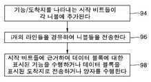
도 16의 흐름도에 도시된 바와 같이, 기능/목적지를 나타내는 시작 비트들이 각 니블에 추가된다(94). 니블들은 i개의 라인들을 경유하여 전송된다(96). 시작 비트들을 사용하여, 데이터 블록에 대한 적합한 기능이 수행되거나 데이터 블록이 적합한 목적지에 전송되거나 상기 양자가 수행된다(98).As shown in the flow chart of FIG. 16, start bits indicating function / destination are added to each
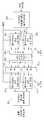
동기화 시스템에서 처리량을 증가시키기 위하여, 클록의 포지티브(짝수의) 및 네거티브(홀수의) 에지(edge) 양자가 블록 데이터를 전송하는데 사용된다. 일 구현예가 도 17에 도시된다. 데이터 블록은 데이터 블록 디멀티플렉싱 디바이스(100)에 의해 수신되고 i개의 니블들의 2개의(짝수의 및 홀수의) 세트들로 디멀티플렉싱된다. i개의 니블들 각 세트는 i개의 P/S 디바이스들(102, 104)의 각각의 세트에 전송된다. 도 17에 도시된 바와 같이, i개의 P/S 디바이스들을 구비하는 홀수의 P/S 디바이스 세트(102)는 인버터(118)에 의해 반전되는 클록 신호를 갖 는다. 결과적으로, 반전된 클록 신호는 시스템 클록에 관하여 반 클록 사이클 지연된다. i개의 MUX들(106)의 세트는 짝수의 P/S 디바이스 세트(104) 및 홀수의 P/S 디바이스 세트(102) 사이를 2배의 클록 레이트로 선택한다. 각 접속을 통해 전송된 결과적인 데이터는 2배의 클록 레이트로 된다. 각 접속의 다른쪽 단부에는 대응하는 DEMUX(108)가 있다. DEMUX들(108)은 2배의 클록 레이트로 순차적으로 각 라인(44)을 짝수의 버퍼(112) 및 홀수의 버퍼(110)에 연결한다. 각 버퍼(112, 110)는 대응하는 짝수 및 홀수 비트를 수신하고 전체 클록 사이클동안 그 값을 유지한다. S/P 디바이스들의 짝수(116) 및 홀수(114) 세트는 짝수 및 홀수 니블들을 회복한다. 데이터 블록 재구성 디바이스(122)는 전송된 니블들로부터 데이터 블록을 재구성한다.To increase throughput in a synchronization system, both the positive (even) and negative (odd) edges of the clock are used to transmit block data. One embodiment is shown in FIG. 17. The data block is received by the data
도 18은 포지티브 및 네거티브 클록 에지를 사용하는 시스템의 라인 상의 데이터 전송을 도시한다. 라인 1상에서 전송되는 짝수 데이터 및 홀수 데이터가 표시된다. 선이 그어진 부분은 조합된 신호에서 네거티브 클록 에지 데이터를 나타내고 선이 그어지지 않은 부분은 짝수의 클록 에지 데이터를 나타낸다. 도시된 바와 같이, 데이터 전송율은 2배로 증가한다.18 shows data transmission on a line of a system using positive and negative clock edges. Even and odd data transmitted on
도 19는 GC 제어기(38) 및 GC(124)간에 사용되는 하이브리드 병렬/직렬 인터페이스의 바람직한 구현예이다. GC 제어 데이터의 16 비트(8 비트 RX 및 8 비트 TX)를 구비하는 것과 같은, 데이터 블록은 GC 제어기(38)로부터 데이터 블록 디멀티플렉싱 디바이스(40)로 전송된다. 데이터 블록은, 2개의 8 비트 니블들과 같은, 2개의 니블들로 디멀티플렉싱된다. 시작 비트가 각 니블에 추가되면, 니블당 9개의 비트들을 구성하는 것과 같이 된다. 2개의 니블들은 2개의 P/S 변환기들(42)을 사용하여 2개의 라인들상에서 전송된다. S/P 변환기들(46)은 시작 비트들을 검출한 때, 수신된 니블들을 병렬 포맷으로 변환한다. 데이터 블록 재구성 디바이스는 GC(124)의 이득을 제어하기 위하여 원래의 16 비트들을 재구성한다. 도 11에서와 같이, 기능이 시작 비트들에 의해 표시되는 경우, AGC(124)는 이득을 조절하기 전에 수신된 블록에 대한 기능을 수행한다.19 is a preferred implementation of the hybrid parallel / serial interface used between the
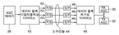
도 20은 GC 제어기(38) 및 수신 이득 제어기(RX GC, 30) 및 송신 이득 제어기(TX GC, 32)사이에 3개의 라인들을 사용하는 하이브리드 병렬/직렬 변환기의 다른 바람직한 구현예이다. GC 제어기(38)는 도 14에서와 같이 적합한 RX 및 TX 이득 값들 및 시작 비트들을 가지고 데이터 블록을 GC(30, 32)에 전송한다. 도 14에서의 시작 비트들이 사용되는 경우, 디바이스 1은 RX GC(30)이고 디바이스 2는 TX GC(32)이다. 데이터 블록 디멀티플렉싱 디바이스(40)는 3개의 라인들상에서 전송하기 위하여 데이터 블록을 3개의 니블들로 디멀티플렉싱한다. 3개의 P/S 변환기들(42) 및 3개의 S/P 변환기들(46)을 사용하는 경우, 이 니블들은 라인들 상에서 순차적으로 전송되고 원래의 니블들로 변환된다. 데이터 블록 재구성 디바이스(48)는 원래의 데이터 블록을 재구성하고 상대적인 증가, 상대적인 감소 및 절대 값과 같은 시작 비트들에 의해 표시되는 기능을 수행한다. 결과적인 데이터는 시작 비트들에 의해 표시되는 RX GC(30) 또는 TX GC(32)에 전송된다.20 is another preferred implementation of a hybrid parallel / serial converter using three lines between the
본 발명에 따른 하이브리드 병렬/직렬 버스 인터페이스는 버스 데이터를 전 송하는 라인들의 수를 감소시킬 수 있다.The hybrid parallel / serial bus interface according to the present invention can reduce the number of lines transmitting bus data.
Claims (57)
Translated fromKoreanApplications Claiming Priority (3)
| Application Number | Priority Date | Filing Date | Title |
|---|---|---|---|
| US09/990,060US7069464B2 (en) | 2001-11-21 | 2001-11-21 | Hybrid parallel/serial bus interface |
| US09/990,060 | 2001-11-21 | ||
| PCT/US2002/037143WO2003047114A1 (en) | 2001-11-21 | 2002-11-19 | Hybrid parallel/serial bus interface |
Related Child Applications (1)
| Application Number | Title | Priority Date | Filing Date |
|---|---|---|---|
| KR1020057015205ADivisionKR100872811B1 (en) | 2001-11-21 | 2002-11-19 | Hybrid parallel/serial bus interface |
Publications (2)
| Publication Number | Publication Date |
|---|---|
| KR20040060984A KR20040060984A (en) | 2004-07-06 |
| KR100566737B1true KR100566737B1 (en) | 2006-04-03 |
Family
ID=25535718
Family Applications (20)
| Application Number | Title | Priority Date | Filing Date |
|---|---|---|---|
| KR2020020018185UCeasedKR200289028Y1 (en) | 2001-11-21 | 2002-06-15 | Base station having a hybrid parallel/serial bus interface |
| KR2020020018184UCeasedKR200288894Y1 (en) | 2001-11-21 | 2002-06-15 | User equipment having a hybrid parallel/serial bus interface |
| KR1020047007575AExpired - Fee RelatedKR100623470B1 (en) | 2001-11-21 | 2002-11-18 | Data transmission method used at base station |
| KR1020047007586AExpired - Fee RelatedKR100623472B1 (en) | 2001-11-21 | 2002-11-18 | User devices with hybrid parallel / serial bus interface |
| KR1020087015441AExpired - Fee RelatedKR100904476B1 (en) | 2001-11-21 | 2002-11-19 | Hybrid parallel/serial bus interface |
| KR1020097020542AExpired - Fee RelatedKR100983567B1 (en) | 2001-11-21 | 2002-11-19 | Hybrid parallel/serial bus interface |
| KR1020057015205AExpired - Fee RelatedKR100872811B1 (en) | 2001-11-21 | 2002-11-19 | Hybrid parallel/serial bus interface |
| KR1020047007584AExpired - Fee RelatedKR100566738B1 (en) | 2001-11-21 | 2002-11-19 | Data transfer method |
| KR1020087030419AExpired - Fee RelatedKR100980756B1 (en) | 2001-11-21 | 2002-11-19 | Hybrid Parallel / Serial Bus Interface |
| KR1020047007567AExpired - Fee RelatedKR100623471B1 (en) | 2001-11-21 | 2002-11-19 | Base Station with Hybrid Parallel / Serial Bus Interface |
| KR1020097010644AExpired - Fee RelatedKR100983569B1 (en) | 2001-11-21 | 2002-11-19 | Hybrid Parallel / Serial Bus Interface |
| KR1020087003361AExpired - Fee RelatedKR100902814B1 (en) | 2001-11-21 | 2002-11-19 | Hybrid parallel/serial bus interface |
| KR1020047007785AExpired - Fee RelatedKR100566737B1 (en) | 2001-11-21 | 2002-11-19 | Hybrid Parallel / Serial Bus Interface |
| KR1020030060188AExpired - Fee RelatedKR100808900B1 (en) | 2001-11-21 | 2003-08-29 | Base Station with Hybrid Parallel / Serial Bus Interface |
| KR1020030060187AExpired - Fee RelatedKR100752558B1 (en) | 2001-11-21 | 2003-08-29 | User device with hybrid parallel / serial bus interface |
| KR10-2003-0074800ACeasedKR20030087603A (en) | 2001-11-21 | 2003-10-24 | Base station having a hybrid parallel/serial bus interface |
| KR1020050087010AExpired - Fee RelatedKR100812858B1 (en) | 2001-11-21 | 2005-09-16 | User equipment having a hybrid parallel/serial bus interface |
| KR1020070055825AExpired - Fee RelatedKR100812859B1 (en) | 2001-11-21 | 2007-06-08 | User equipment having a hybrid parallel/serial bus interface |
| KR1020070090521ACeasedKR20070101189A (en) | 2001-11-21 | 2007-09-06 | Base Station with Hybrid Parallel / Serial Bus Interface |
| KR1020070140251AWithdrawnKR20080007423A (en) | 2001-11-21 | 2007-12-28 | User device with hybrid parallel / serial bus interface |
Family Applications Before (12)
| Application Number | Title | Priority Date | Filing Date |
|---|---|---|---|
| KR2020020018185UCeasedKR200289028Y1 (en) | 2001-11-21 | 2002-06-15 | Base station having a hybrid parallel/serial bus interface |
| KR2020020018184UCeasedKR200288894Y1 (en) | 2001-11-21 | 2002-06-15 | User equipment having a hybrid parallel/serial bus interface |
| KR1020047007575AExpired - Fee RelatedKR100623470B1 (en) | 2001-11-21 | 2002-11-18 | Data transmission method used at base station |
| KR1020047007586AExpired - Fee RelatedKR100623472B1 (en) | 2001-11-21 | 2002-11-18 | User devices with hybrid parallel / serial bus interface |
| KR1020087015441AExpired - Fee RelatedKR100904476B1 (en) | 2001-11-21 | 2002-11-19 | Hybrid parallel/serial bus interface |
| KR1020097020542AExpired - Fee RelatedKR100983567B1 (en) | 2001-11-21 | 2002-11-19 | Hybrid parallel/serial bus interface |
| KR1020057015205AExpired - Fee RelatedKR100872811B1 (en) | 2001-11-21 | 2002-11-19 | Hybrid parallel/serial bus interface |
| KR1020047007584AExpired - Fee RelatedKR100566738B1 (en) | 2001-11-21 | 2002-11-19 | Data transfer method |
| KR1020087030419AExpired - Fee RelatedKR100980756B1 (en) | 2001-11-21 | 2002-11-19 | Hybrid Parallel / Serial Bus Interface |
| KR1020047007567AExpired - Fee RelatedKR100623471B1 (en) | 2001-11-21 | 2002-11-19 | Base Station with Hybrid Parallel / Serial Bus Interface |
| KR1020097010644AExpired - Fee RelatedKR100983569B1 (en) | 2001-11-21 | 2002-11-19 | Hybrid Parallel / Serial Bus Interface |
| KR1020087003361AExpired - Fee RelatedKR100902814B1 (en) | 2001-11-21 | 2002-11-19 | Hybrid parallel/serial bus interface |
Family Applications After (7)
| Application Number | Title | Priority Date | Filing Date |
|---|---|---|---|
| KR1020030060188AExpired - Fee RelatedKR100808900B1 (en) | 2001-11-21 | 2003-08-29 | Base Station with Hybrid Parallel / Serial Bus Interface |
| KR1020030060187AExpired - Fee RelatedKR100752558B1 (en) | 2001-11-21 | 2003-08-29 | User device with hybrid parallel / serial bus interface |
| KR10-2003-0074800ACeasedKR20030087603A (en) | 2001-11-21 | 2003-10-24 | Base station having a hybrid parallel/serial bus interface |
| KR1020050087010AExpired - Fee RelatedKR100812858B1 (en) | 2001-11-21 | 2005-09-16 | User equipment having a hybrid parallel/serial bus interface |
| KR1020070055825AExpired - Fee RelatedKR100812859B1 (en) | 2001-11-21 | 2007-06-08 | User equipment having a hybrid parallel/serial bus interface |
| KR1020070090521ACeasedKR20070101189A (en) | 2001-11-21 | 2007-09-06 | Base Station with Hybrid Parallel / Serial Bus Interface |
| KR1020070140251AWithdrawnKR20080007423A (en) | 2001-11-21 | 2007-12-28 | User device with hybrid parallel / serial bus interface |
Country Status (16)
| Country | Link |
|---|---|
| US (6) | US7069464B2 (en) |
| EP (3) | EP1575173B1 (en) |
| JP (1) | JP4384912B2 (en) |
| KR (20) | KR200289028Y1 (en) |
| CN (8) | CN2547071Y (en) |
| AR (5) | AR037578A1 (en) |
| AT (1) | ATE366484T1 (en) |
| AU (1) | AU2002346447A1 (en) |
| CA (2) | CA2467851C (en) |
| DE (2) | DE60225487T2 (en) |
| ES (1) | ES2287339T3 (en) |
| MX (1) | MXPA04004789A (en) |
| MY (5) | MY130932A (en) |
| NO (1) | NO20042546L (en) |
| TW (17) | TW590346U (en) |
| WO (1) | WO2003047114A1 (en) |
Cited By (1)
| Publication number | Priority date | Publication date | Assignee | Title |
|---|---|---|---|---|
| KR20160027870A (en)* | 2014-08-29 | 2016-03-10 | 삼성전자주식회사 | Data interface and data transmit method |
Families Citing this family (40)
| Publication number | Priority date | Publication date | Assignee | Title |
|---|---|---|---|---|
| US7391865B2 (en) | 1999-09-20 | 2008-06-24 | Security First Corporation | Secure data parser method and system |
| CA2467844C (en)* | 2001-11-21 | 2008-04-01 | Interdigital Technology Corporation | Method employed by a base station for transferring data |
| JP2005510800A (en)* | 2001-11-21 | 2005-04-21 | インターディジタル テクノロジー コーポレイション | User equipment (UE) with hybrid parallel / serial bus interface |
| US7069464B2 (en)* | 2001-11-21 | 2006-06-27 | Interdigital Technology Corporation | Hybrid parallel/serial bus interface |
| US7349466B2 (en)* | 2002-03-28 | 2008-03-25 | Seagate Technology Llc | Parallel interface transmission using a single multi-frequency composite signal |
| US20050002728A1 (en)* | 2003-07-01 | 2005-01-06 | Isaac Weiser | Plastic connector for connecting parts and method therefor |
| JP4230381B2 (en)* | 2004-02-25 | 2009-02-25 | 旭化成エレクトロニクス株式会社 | LVDS system, transmission side circuit thereof, and reception side circuit thereof |
| JP3780419B2 (en)* | 2004-03-09 | 2006-05-31 | セイコーエプソン株式会社 | Data transfer control device and electronic device |
| CN102609640B (en) | 2004-10-25 | 2015-07-15 | 安全第一公司 | Secure data parser method and system |
| KR101194473B1 (en)* | 2004-11-16 | 2012-10-24 | 엔엑스피 비 브이 | Bus communication system |
| DE102005001894A1 (en)* | 2005-01-14 | 2006-08-03 | Infineon Technologies Ag | Synchronous parallel-to-serial converter |
| ATE376728T1 (en)* | 2005-07-05 | 2007-11-15 | Alcatel Lucent | BASE STATION AND METHOD FOR ASSIGNING HS-DSCH CHANNELING CODES IN A WIRELESS COMMUNICATIONS SYSTEM |
| DE602005002050T2 (en)* | 2005-07-05 | 2008-05-15 | Alcatel Lucent | Method for transmitting signals in a radio network |
| US7659838B2 (en)* | 2005-08-03 | 2010-02-09 | Altera Corporation | Deserializer circuitry for high-speed serial data receivers on programmable logic device integrated circuits |
| US20070081183A1 (en)* | 2005-10-10 | 2007-04-12 | Fugate Earl L | Printing apparatus consumable data communication |
| EP1952575B1 (en) | 2005-11-18 | 2017-12-27 | Security First Corp. | Secure data parser method and system |
| CN101689230A (en) | 2006-12-05 | 2010-03-31 | 安全第一公司 | Improved Tape Backup Method |
| US7827433B1 (en)* | 2007-05-16 | 2010-11-02 | Altera Corporation | Time-multiplexed routing for reducing pipelining registers |
| BRPI1013062A2 (en) | 2009-05-19 | 2016-04-05 | Security First Corp | systems and methods to protect cloud data |
| CN101925119B (en)* | 2009-06-09 | 2013-03-27 | 普天信息技术研究院有限公司 | Communication method, system and device for enhancing system capacity |
| KR101283844B1 (en)* | 2009-06-19 | 2013-07-08 | 후지쯔 가부시끼가이샤 | Data transfer method, code conversion circuit, and device |
| CN106230872A (en) | 2009-11-25 | 2016-12-14 | 安全第公司 | To moving medial according to the system and method protected |
| US8510487B2 (en)* | 2010-02-11 | 2013-08-13 | Silicon Image, Inc. | Hybrid interface for serial and parallel communication |
| WO2011123692A2 (en) | 2010-03-31 | 2011-10-06 | Orsini Rick L | Systems and methods for securing data in motion |
| CN103238305A (en) | 2010-05-28 | 2013-08-07 | 安全第一公司 | Accelerator system for use with secure data storage |
| US9112520B2 (en) | 2010-08-12 | 2015-08-18 | Mediatek Inc. | Transmission interface and system using the same |
| US8648739B2 (en) | 2010-08-12 | 2014-02-11 | Mediatek Inc. | Transmission interface and system using the same |
| WO2012040231A2 (en) | 2010-09-20 | 2012-03-29 | Orsini Rick L | Systems and methods for secure data sharing |
| US8760188B2 (en) | 2011-06-30 | 2014-06-24 | Silicon Image, Inc. | Configurable multi-dimensional driver and receiver |
| US9071243B2 (en) | 2011-06-30 | 2015-06-30 | Silicon Image, Inc. | Single ended configurable multi-mode driver |
| US8885435B2 (en) | 2012-09-18 | 2014-11-11 | Silicon Image, Inc. | Interfacing between integrated circuits with asymmetric voltage swing |
| FR2999368B1 (en)* | 2012-12-07 | 2018-05-18 | Safran Electronics & Defense Sas | DEVICE FOR INPUTTING OUTPUTS TRANSFERRING AND / OR RECEIVING DATA TO A CONTROL DEVICE. |
| US9306563B2 (en) | 2013-02-19 | 2016-04-05 | Lattice Semiconductor Corporation | Configurable single-ended driver |
| KR101463775B1 (en)* | 2013-05-06 | 2014-11-24 | 한국전자통신연구원 | Multi-frame data processing apparatus using frame disassembling and method thereof |
| EP3058571A1 (en) | 2013-10-15 | 2016-08-24 | Rambus Inc. | Load reduced memory module |
| US10114789B2 (en) | 2015-01-08 | 2018-10-30 | Samsung Electronics Co., Ltd. | System on chip for packetizing multiple bytes and data processing system including the same |
| US20170109248A1 (en)* | 2015-10-20 | 2017-04-20 | Quanta Computer Inc. | Sharing bus port by multiple bus hosts |
| CN106254165B (en)* | 2016-09-30 | 2019-09-06 | 新华三技术有限公司 | Interface processing method and processing device |
| JP7140352B2 (en)* | 2018-01-18 | 2022-09-21 | ソニーセミコンダクタソリューションズ株式会社 | signal processor |
| CN113886300B (en)* | 2021-09-23 | 2024-05-03 | 珠海一微半导体股份有限公司 | Clock data self-adaptive recovery system and chip of bus interface |
Family Cites Families (61)
| Publication number | Priority date | Publication date | Assignee | Title |
|---|---|---|---|---|
| US4675861A (en)* | 1984-11-28 | 1987-06-23 | Adc Telecommunications, Inc. | Fiber optic multiplexer |
| KR910002357B1 (en)* | 1988-02-23 | 1991-04-20 | 삼성전자 주식회사 | Channel Assignment Circuit of Digital Exchange |
| US5018142A (en)* | 1988-03-04 | 1991-05-21 | Digital Equipment Corporation | Technique for organizing and coding serial binary data from a plurality of data lines for transmission over a single transmission line |
| EP0403663B1 (en)* | 1989-01-09 | 1996-07-17 | Fujitsu Limited | Digital signal multiplexer and separator |
| JPH04119034A (en)* | 1990-09-07 | 1992-04-20 | Fujitsu Ltd | Duplex loop control method for information processing systems |
| JPH056335A (en)* | 1991-06-27 | 1993-01-14 | Nec Eng Ltd | Inter-device interface system |
| US5347268A (en)* | 1991-10-18 | 1994-09-13 | Motorola, Inc. | Data handler for handling data having multiple data formats |
| US5390041A (en)* | 1991-11-06 | 1995-02-14 | Cray Research, Inc. | Fiber optic channel extender interface method and apparatus |
| JPH05160819A (en)* | 1991-12-03 | 1993-06-25 | Nec Eng Ltd | Data transfer equipment |
| JPH05250316A (en)* | 1992-03-05 | 1993-09-28 | Nec Eng Ltd | Inter-device interface system |
| CA2132097A1 (en)* | 1992-03-25 | 1993-09-30 | John D. Acton | Fiber optic memory coupling system |
| US5327126A (en) | 1992-06-26 | 1994-07-05 | Hewlett-Packard Company | Apparatus for and method of parallel justifying and dejustifying data in accordance with a predetermined mapping |
| CA2114526A1 (en) | 1992-06-29 | 1994-01-06 | Clifford H. Kraft | High-speed time-multiplexed data transmission system |
| JP2732759B2 (en) | 1992-07-15 | 1998-03-30 | 沖電気工業株式会社 | Frame synchronization control method |
| JPH06334537A (en) | 1993-05-21 | 1994-12-02 | Fujitsu Ltd | Serial / parallel conversion circuit with uncertainty removal function |
| US5602780A (en) | 1993-10-20 | 1997-02-11 | Texas Instruments Incorporated | Serial to parallel and parallel to serial architecture for a RAM based FIFO memory |
| US5570089A (en) | 1994-02-16 | 1996-10-29 | International Business Machines Corporation | Method and apparatus for providing data stream for cost effective transmission links |
| JPH07325667A (en) | 1994-06-01 | 1995-12-12 | Hitachi Ltd | Data transfer method and disk control LSI |
| WO1996013902A1 (en) | 1994-11-01 | 1996-05-09 | Virtual Machine Works, Inc. | Programmable multiplexing input/output port |
| JPH08180016A (en)* | 1994-12-27 | 1996-07-12 | Mitsubishi Electric Corp | Communication interface circuit |
| US5768529A (en) | 1995-05-05 | 1998-06-16 | Silicon Graphics, Inc. | System and method for the synchronous transmission of data in a communication network utilizing a source clock signal to latch serial data into first registers and a handshake signal to latch parallel data into second registers |
| US5635933A (en) | 1995-06-30 | 1997-06-03 | Quantum Corporation | Rate 16/17 (d=0,G=6/I=7) modulation code for a magnetic recording channel |
| DE19534156C1 (en) | 1995-09-14 | 1996-10-17 | Siemens Ag | Time multiplex data packet transmission method |
| JPH09135246A (en)* | 1995-11-08 | 1997-05-20 | Fujitsu Ltd | Asynchronous communication system |
| KR970056528A (en) | 1995-12-13 | 1997-07-31 | 배순훈 | Analog Bus / I ^ 2C Bus Protocol Converters |
| US5784003A (en) | 1996-03-25 | 1998-07-21 | I-Cube, Inc. | Network switch with broadcast support |
| US5926120A (en) | 1996-03-28 | 1999-07-20 | National Semiconductor Corporation | Multi-channel parallel to serial and serial to parallel conversion using a RAM array |
| JPH09322158A (en) | 1996-05-31 | 1997-12-12 | Matsushita Electric Ind Co Ltd | Image signal transmission device |
| JPH1063617A (en) | 1996-08-15 | 1998-03-06 | Sony Corp | Serial communication device |
| US5963638A (en) | 1996-09-04 | 1999-10-05 | Teltrend, Inc. | Adjustable hybrid having improved biasing configuration |
| ES2119707B1 (en) | 1996-11-19 | 1999-06-16 | Telefonica Nacional Espana Co | LINE INTERFACE CIRCUIT FOR WIDE BAND. |
| US6310876B1 (en) | 1997-02-14 | 2001-10-30 | Advanced Micro Devices, Inc. | Method and apparatus for managing bin chains in a memory |
| US5812881A (en)* | 1997-04-10 | 1998-09-22 | International Business Machines Corporation | Handshake minimizing serial to parallel bus interface in a data processing system |
| US5991282A (en) | 1997-05-28 | 1999-11-23 | Telefonaktiebolaget Lm Ericsson | Radio communication system with diversity reception on a time-slot by time-slot basis |
| US6295457B1 (en) | 1997-06-27 | 2001-09-25 | Lucent Technologies Inc. | Integrated cellular telephone basestation with Internet gateway |
| JPH11167548A (en) | 1997-08-28 | 1999-06-22 | Canon Inc | Data transmission system |
| US6058106A (en) | 1997-10-20 | 2000-05-02 | Motorola, Inc. | Network protocol method, access point device and peripheral devices for providing for an efficient centrally coordinated peer-to-peer wireless communications network |
| JPH11127219A (en)* | 1997-10-23 | 1999-05-11 | Daio Denshi Kk | Data transfer equipment |
| US6040792A (en) | 1997-11-19 | 2000-03-21 | In-System Design, Inc. | Universal serial bus to parallel bus signal converter and method of conversion |
| US6081523A (en) | 1997-12-05 | 2000-06-27 | Advanced Micro Devices, Inc. | Arrangement for transmitting packet data segments from a media access controller across multiple physical links |
| JPH11345190A (en)* | 1998-06-02 | 1999-12-14 | Nec Corp | Information transfer device |
| US6128244A (en) | 1998-06-04 | 2000-10-03 | Micron Technology, Inc. | Method and apparatus for accessing one of a plurality of memory units within an electronic memory device |
| US6333926B1 (en) | 1998-08-11 | 2001-12-25 | Nortel Networks Limited | Multiple user CDMA basestation modem |
| US6285960B1 (en) | 1998-10-07 | 2001-09-04 | Cisco Technology, Inc. | Method and apparatus for a router line card with adaptive selectable gain control |
| JP2000200121A (en) | 1998-10-07 | 2000-07-18 | Matsushita Electric Ind Co Ltd | Data processing device |
| US6356374B1 (en) | 1998-10-09 | 2002-03-12 | Scientific-Atlanta, Inc. | Digital optical transmitter |
| CN1147774C (en)* | 1998-10-23 | 2004-04-28 | 宏基股份有限公司 | Computer device and method for entering operation mode from power-saving mode |
| JP2000224229A (en) | 1999-01-29 | 2000-08-11 | Victor Co Of Japan Ltd | Transmission method, transmitter and receiver |
| US6356369B1 (en) | 1999-02-22 | 2002-03-12 | Scientific-Atlanta, Inc. | Digital optical transmitter for processing externally generated information in the reverse path |
| US6434654B1 (en)* | 1999-03-26 | 2002-08-13 | Koninklijke Philips Electronics N.V. | System bus with a variable width selectivity configurable at initialization |
| JP3409739B2 (en) | 1999-05-25 | 2003-05-26 | 日本電気株式会社 | Automatic skew adjuster |
| US6611217B2 (en) | 1999-06-11 | 2003-08-26 | International Business Machines Corporation | Initialization system for recovering bits and group of bits from a communications channel |
| US6792003B1 (en) | 1999-08-12 | 2004-09-14 | Nortel Networks Limited | Method and apparatus for transporting and aligning data across multiple serial data streams |
| TW444448B (en) | 1999-10-07 | 2001-07-01 | Chunghwa Telecom Lab | CDMA base station system |
| JP2001236305A (en)* | 2000-02-22 | 2001-08-31 | Hitachi Ltd | Semiconductor integrated circuit and data processing device |
| US6961347B1 (en) | 2000-06-20 | 2005-11-01 | Hewlett-Packard Development Company, L.P. | High-speed interconnection link having automated lane reordering |
| JP2002064506A (en) | 2000-08-17 | 2002-02-28 | Ricoh Co Ltd | Data transfer method |
| CN1140901C (en)* | 2000-11-21 | 2004-03-03 | 扬智科技股份有限公司 | Decoding system and method for floppy disk |
| US6447250B1 (en)* | 2000-11-27 | 2002-09-10 | General Electric Company | Non-integral fan platform |
| JP2003131815A (en)* | 2001-10-22 | 2003-05-09 | Fujitsu Media Device Kk | Data transfer system of serial interface |
| US7069464B2 (en) | 2001-11-21 | 2006-06-27 | Interdigital Technology Corporation | Hybrid parallel/serial bus interface |
- 2001
- 2001-11-21USUS09/990,060patent/US7069464B2/ennot_activeExpired - Fee Related
- 2002
- 2002-02-22USUS10/080,480patent/US6823468B2/ennot_activeExpired - Lifetime
- 2002-02-22USUS10/080,899patent/US6823469B2/ennot_activeExpired - Lifetime
- 2002-02-22USUS10/081,466patent/US6829718B2/ennot_activeExpired - Lifetime
- 2002-02-22USUS10/080,817patent/US6848018B2/ennot_activeExpired - Lifetime
- 2002-05-27TWTW091207708Upatent/TW590346U/ennot_activeIP Right Cessation
- 2002-05-27TWTW091207707Upatent/TW592413U/ennot_activeIP Right Cessation
- 2002-06-07CNCN02236955Upatent/CN2547071Y/ennot_activeExpired - Lifetime
- 2002-06-07CNCN02236954Upatent/CN2547084Y/ennot_activeExpired - Lifetime
- 2002-06-15KRKR2020020018185Upatent/KR200289028Y1/ennot_activeCeased
- 2002-06-15KRKR2020020018184Upatent/KR200288894Y1/ennot_activeCeased
- 2002-11-18KRKR1020047007575Apatent/KR100623470B1/ennot_activeExpired - Fee Related
- 2002-11-18EPEP05104800Apatent/EP1575173B1/ennot_activeExpired - Lifetime
- 2002-11-18KRKR1020047007586Apatent/KR100623472B1/ennot_activeExpired - Fee Related
- 2002-11-18EPEP05104801Apatent/EP1575174B1/ennot_activeExpired - Lifetime
- 2002-11-18DEDE60225487Tpatent/DE60225487T2/ennot_activeExpired - Lifetime
- 2002-11-18CNCNA2007101274916Apatent/CN101079855A/enactivePending
- 2002-11-18CNCNA2007101669889Apatent/CN101150546A/enactivePending
- 2002-11-19EPEP02784511Apatent/EP1456957B1/ennot_activeExpired - Lifetime
- 2002-11-19AUAU2002346447Apatent/AU2002346447A1/ennot_activeAbandoned
- 2002-11-19WOPCT/US2002/037143patent/WO2003047114A1/enactiveApplication Filing
- 2002-11-19KRKR1020087015441Apatent/KR100904476B1/ennot_activeExpired - Fee Related
- 2002-11-19JPJP2003548413Apatent/JP4384912B2/ennot_activeExpired - Fee Related
- 2002-11-19KRKR1020097020542Apatent/KR100983567B1/ennot_activeExpired - Fee Related
- 2002-11-19KRKR1020057015205Apatent/KR100872811B1/ennot_activeExpired - Fee Related
- 2002-11-19KRKR1020047007584Apatent/KR100566738B1/ennot_activeExpired - Fee Related
- 2002-11-19ESES02784511Tpatent/ES2287339T3/ennot_activeExpired - Lifetime
- 2002-11-19KRKR1020087030419Apatent/KR100980756B1/ennot_activeExpired - Fee Related
- 2002-11-19KRKR1020047007567Apatent/KR100623471B1/ennot_activeExpired - Fee Related
- 2002-11-19ATAT02784511Tpatent/ATE366484T1/ennot_activeIP Right Cessation
- 2002-11-19CNCNA2007101423323Apatent/CN101106505A/enactivePending
- 2002-11-19KRKR1020097010644Apatent/KR100983569B1/ennot_activeExpired - Fee Related
- 2002-11-19CNCNA2009100044051Apatent/CN101488758A/enactivePending
- 2002-11-19KRKR1020087003361Apatent/KR100902814B1/ennot_activeExpired - Fee Related
- 2002-11-19CNCNA2008101743152Apatent/CN101399791A/enactivePending
- 2002-11-19DEDE60221042Tpatent/DE60221042T2/ennot_activeExpired - Lifetime
- 2002-11-19KRKR1020047007785Apatent/KR100566737B1/ennot_activeExpired - Fee Related
- 2002-11-19CNCNB028231171Apatent/CN100461635C/ennot_activeExpired - Fee Related
- 2002-11-19MXMXPA04004789Apatent/MXPA04004789A/enactiveIP Right Grant
- 2002-11-19CACA002467851Apatent/CA2467851C/ennot_activeExpired - Fee Related
- 2002-11-19CACA002614598Apatent/CA2614598A1/ennot_activeAbandoned
- 2002-11-21TWTW098102122Apatent/TW200947219A/enunknown
- 2002-11-21TWTW091134138Apatent/TWI261758B/ennot_activeIP Right Cessation
- 2002-11-21TWTW097151302Apatent/TW200945050A/enunknown
- 2002-11-21MYMYPI20024361Apatent/MY130932A/enunknown
- 2002-11-21ARARP020104470Apatent/AR037578A1/ennot_activeApplication Discontinuation
- 2002-11-21ARARP020104468Apatent/AR037576A1/ennot_activeApplication Discontinuation
- 2002-11-21MYMYPI20024359Apatent/MY136300A/enunknown
- 2002-11-21MYMYPI20024363Apatent/MY131176A/enunknown
- 2002-11-21TWTW096124059Apatent/TWI325111B/ennot_activeIP Right Cessation
- 2002-11-21TWTW092128231Apatent/TWI293415B/ennot_activeIP Right Cessation
- 2002-11-21ARARP020104472Apatent/AR037660A1/ennot_activeApplication Discontinuation
- 2002-11-21ARARP020104471Apatent/AR037579A1/ennot_activeApplication Discontinuation
- 2002-11-21MYMYPI20024362Apatent/MY136304A/enunknown
- 2002-11-21TWTW098102129Apatent/TW200947220A/enunknown
- 2002-11-21TWTW092127557Apatent/TWI323115B/enactive
- 2002-11-21TWTW098102130Apatent/TW200947209A/enunknown
- 2002-11-21TWTW095142150Apatent/TWI332617B/ennot_activeIP Right Cessation
- 2002-11-21TWTW094140848Apatent/TWI294576B/ennot_activeIP Right Cessation
- 2002-11-21TWTW092127354Apatent/TWI272499B/ennot_activeIP Right Cessation
- 2002-11-21MYMYPI20024360Apatent/MY130439A/enunknown
- 2002-11-21ARARP020104469Apatent/AR037577A1/ennot_activeApplication Discontinuation
- 2002-11-21TWTW098102121Apatent/TW201002000A/enunknown
- 2002-11-21TWTW094140851Apatent/TWI305988B/ennot_activeIP Right Cessation
- 2002-11-21TWTW094140850Apatent/TWI315145B/ennot_activeIP Right Cessation
- 2002-11-21TWTW095128936Apatent/TWI330322B/ennot_activeIP Right Cessation
- 2003
- 2003-08-29KRKR1020030060188Apatent/KR100808900B1/ennot_activeExpired - Fee Related
- 2003-08-29KRKR1020030060187Apatent/KR100752558B1/ennot_activeExpired - Fee Related
- 2003-10-24KRKR10-2003-0074800Apatent/KR20030087603A/ennot_activeCeased
- 2004
- 2004-06-17NONO20042546Apatent/NO20042546L/ennot_activeApplication Discontinuation
- 2005
- 2005-09-16KRKR1020050087010Apatent/KR100812858B1/ennot_activeExpired - Fee Related
- 2007
- 2007-06-08KRKR1020070055825Apatent/KR100812859B1/ennot_activeExpired - Fee Related
- 2007-09-06KRKR1020070090521Apatent/KR20070101189A/ennot_activeCeased
- 2007-12-28KRKR1020070140251Apatent/KR20080007423A/ennot_activeWithdrawn
- 2008
- 2008-07-03USUS12/167,938patent/US7752482B2/ennot_activeExpired - Fee Related
Cited By (2)
| Publication number | Priority date | Publication date | Assignee | Title |
|---|---|---|---|---|
| KR20160027870A (en)* | 2014-08-29 | 2016-03-10 | 삼성전자주식회사 | Data interface and data transmit method |
| KR102195408B1 (en)* | 2014-08-29 | 2020-12-30 | 삼성전자주식회사 | Data interface and data transmit method |
Also Published As
Similar Documents
| Publication | Publication Date | Title |
|---|---|---|
| KR100566737B1 (en) | Hybrid Parallel / Serial Bus Interface | |
| CA2467844C (en) | Method employed by a base station for transferring data | |
| EP1446584A2 (en) | BASE STATION HAVING A HYBRID PARALLEL/SERIAL BUS INTERFACE | |
| CA2467847A1 (en) | Method of transferring data |
Legal Events
| Date | Code | Title | Description |
|---|---|---|---|
| A201 | Request for examination | ||
| PA0105 | International application | St.27 status event code:A-0-1-A10-A15-nap-PA0105 | |
| PA0201 | Request for examination | St.27 status event code:A-1-2-D10-D11-exm-PA0201 | |
| PG1501 | Laying open of application | St.27 status event code:A-1-1-Q10-Q12-nap-PG1501 | |
| A107 | Divisional application of patent | ||
| PA0104 | Divisional application for international application | St.27 status event code:A-0-1-A10-A18-div-PA0104 St.27 status event code:A-0-1-A10-A16-div-PA0104 | |
| E701 | Decision to grant or registration of patent right | ||
| PE0701 | Decision of registration | St.27 status event code:A-1-2-D10-D22-exm-PE0701 | |
| GRNT | Written decision to grant | ||
| PR0701 | Registration of establishment | St.27 status event code:A-2-4-F10-F11-exm-PR0701 | |
| PR1002 | Payment of registration fee | St.27 status event code:A-2-2-U10-U12-oth-PR1002 Fee payment year number:1 | |
| PG1601 | Publication of registration | St.27 status event code:A-4-4-Q10-Q13-nap-PG1601 | |
| R18-X000 | Changes to party contact information recorded | St.27 status event code:A-5-5-R10-R18-oth-X000 | |
| PR1001 | Payment of annual fee | St.27 status event code:A-4-4-U10-U11-oth-PR1001 Fee payment year number:4 | |
| PR1001 | Payment of annual fee | St.27 status event code:A-4-4-U10-U11-oth-PR1001 Fee payment year number:5 | |
| PR1001 | Payment of annual fee | St.27 status event code:A-4-4-U10-U11-oth-PR1001 Fee payment year number:6 | |
| PR1001 | Payment of annual fee | St.27 status event code:A-4-4-U10-U11-oth-PR1001 Fee payment year number:7 | |
| R18-X000 | Changes to party contact information recorded | St.27 status event code:A-5-5-R10-R18-oth-X000 | |
| FPAY | Annual fee payment | Payment date:20130219 Year of fee payment:8 | |
| PR1001 | Payment of annual fee | St.27 status event code:A-4-4-U10-U11-oth-PR1001 Fee payment year number:8 | |
| FPAY | Annual fee payment | Payment date:20140220 Year of fee payment:9 | |
| PR1001 | Payment of annual fee | St.27 status event code:A-4-4-U10-U11-oth-PR1001 Fee payment year number:9 | |
| FPAY | Annual fee payment | Payment date:20150309 Year of fee payment:10 | |
| PR1001 | Payment of annual fee | St.27 status event code:A-4-4-U10-U11-oth-PR1001 Fee payment year number:10 | |
| PR1001 | Payment of annual fee | St.27 status event code:A-4-4-U10-U11-oth-PR1001 Fee payment year number:11 | |
| LAPS | Lapse due to unpaid annual fee | ||
| PC1903 | Unpaid annual fee | St.27 status event code:A-4-4-U10-U13-oth-PC1903 Not in force date:20170328 Payment event data comment text:Termination Category : DEFAULT_OF_REGISTRATION_FEE | |
| PC1903 | Unpaid annual fee | St.27 status event code:N-4-6-H10-H13-oth-PC1903 Ip right cessation event data comment text:Termination Category : DEFAULT_OF_REGISTRATION_FEE Not in force date:20170328 |