KR100566584B1 - Artificial hip joint femoral stem and neck processing method of the femoral stem - Google Patents
Artificial hip joint femoral stem and neck processing method of the femoral stemDownload PDFInfo
- Publication number
- KR100566584B1 KR100566584B1KR1020040038359AKR20040038359AKR100566584B1KR 100566584 B1KR100566584 B1KR 100566584B1KR 1020040038359 AKR1020040038359 AKR 1020040038359AKR 20040038359 AKR20040038359 AKR 20040038359AKR 100566584 B1KR100566584 B1KR 100566584B1
- Authority
- KR
- South Korea
- Prior art keywords
- femoral stem
- artificial
- neck
- cutting surface
- insert
- Prior art date
- Legal status (The legal status is an assumption and is not a legal conclusion. Google has not performed a legal analysis and makes no representation as to the accuracy of the status listed.)
- Expired - Lifetime
Links
Images


Classifications
- A—HUMAN NECESSITIES
- A61—MEDICAL OR VETERINARY SCIENCE; HYGIENE
- A61F—FILTERS IMPLANTABLE INTO BLOOD VESSELS; PROSTHESES; DEVICES PROVIDING PATENCY TO, OR PREVENTING COLLAPSING OF, TUBULAR STRUCTURES OF THE BODY, e.g. STENTS; ORTHOPAEDIC, NURSING OR CONTRACEPTIVE DEVICES; FOMENTATION; TREATMENT OR PROTECTION OF EYES OR EARS; BANDAGES, DRESSINGS OR ABSORBENT PADS; FIRST-AID KITS
- A61F2/00—Filters implantable into blood vessels; Prostheses, i.e. artificial substitutes or replacements for parts of the body; Appliances for connecting them with the body; Devices providing patency to, or preventing collapsing of, tubular structures of the body, e.g. stents
- A61F2/02—Prostheses implantable into the body
- A61F2/30—Joints
- A61F2/32—Joints for the hip
- A61F2/36—Femoral heads ; Femoral endoprostheses
- A61F2/3662—Femoral shafts
- A—HUMAN NECESSITIES
- A61—MEDICAL OR VETERINARY SCIENCE; HYGIENE
- A61F—FILTERS IMPLANTABLE INTO BLOOD VESSELS; PROSTHESES; DEVICES PROVIDING PATENCY TO, OR PREVENTING COLLAPSING OF, TUBULAR STRUCTURES OF THE BODY, e.g. STENTS; ORTHOPAEDIC, NURSING OR CONTRACEPTIVE DEVICES; FOMENTATION; TREATMENT OR PROTECTION OF EYES OR EARS; BANDAGES, DRESSINGS OR ABSORBENT PADS; FIRST-AID KITS
- A61F2/00—Filters implantable into blood vessels; Prostheses, i.e. artificial substitutes or replacements for parts of the body; Appliances for connecting them with the body; Devices providing patency to, or preventing collapsing of, tubular structures of the body, e.g. stents
- A61F2/02—Prostheses implantable into the body
- A61F2/30—Joints
- A61F2/32—Joints for the hip
- A61F2/34—Acetabular cups
- A—HUMAN NECESSITIES
- A61—MEDICAL OR VETERINARY SCIENCE; HYGIENE
- A61F—FILTERS IMPLANTABLE INTO BLOOD VESSELS; PROSTHESES; DEVICES PROVIDING PATENCY TO, OR PREVENTING COLLAPSING OF, TUBULAR STRUCTURES OF THE BODY, e.g. STENTS; ORTHOPAEDIC, NURSING OR CONTRACEPTIVE DEVICES; FOMENTATION; TREATMENT OR PROTECTION OF EYES OR EARS; BANDAGES, DRESSINGS OR ABSORBENT PADS; FIRST-AID KITS
- A61F2/00—Filters implantable into blood vessels; Prostheses, i.e. artificial substitutes or replacements for parts of the body; Appliances for connecting them with the body; Devices providing patency to, or preventing collapsing of, tubular structures of the body, e.g. stents
- A61F2/02—Prostheses implantable into the body
- A61F2/30—Joints
- A61F2002/30001—Additional features of subject-matter classified in A61F2/28, A61F2/30 and subgroups thereof
- A61F2002/30108—Shapes
- A61F2002/3011—Cross-sections or two-dimensional shapes
- A61F2002/30112—Rounded shapes, e.g. with rounded corners
- A—HUMAN NECESSITIES
- A61—MEDICAL OR VETERINARY SCIENCE; HYGIENE
- A61F—FILTERS IMPLANTABLE INTO BLOOD VESSELS; PROSTHESES; DEVICES PROVIDING PATENCY TO, OR PREVENTING COLLAPSING OF, TUBULAR STRUCTURES OF THE BODY, e.g. STENTS; ORTHOPAEDIC, NURSING OR CONTRACEPTIVE DEVICES; FOMENTATION; TREATMENT OR PROTECTION OF EYES OR EARS; BANDAGES, DRESSINGS OR ABSORBENT PADS; FIRST-AID KITS
- A61F2/00—Filters implantable into blood vessels; Prostheses, i.e. artificial substitutes or replacements for parts of the body; Appliances for connecting them with the body; Devices providing patency to, or preventing collapsing of, tubular structures of the body, e.g. stents
- A61F2/02—Prostheses implantable into the body
- A61F2/30—Joints
- A61F2002/30001—Additional features of subject-matter classified in A61F2/28, A61F2/30 and subgroups thereof
- A61F2002/30108—Shapes
- A61F2002/3011—Cross-sections or two-dimensional shapes
- A61F2002/30138—Convex polygonal shapes
- A61F2002/30153—Convex polygonal shapes rectangular
- A—HUMAN NECESSITIES
- A61—MEDICAL OR VETERINARY SCIENCE; HYGIENE
- A61F—FILTERS IMPLANTABLE INTO BLOOD VESSELS; PROSTHESES; DEVICES PROVIDING PATENCY TO, OR PREVENTING COLLAPSING OF, TUBULAR STRUCTURES OF THE BODY, e.g. STENTS; ORTHOPAEDIC, NURSING OR CONTRACEPTIVE DEVICES; FOMENTATION; TREATMENT OR PROTECTION OF EYES OR EARS; BANDAGES, DRESSINGS OR ABSORBENT PADS; FIRST-AID KITS
- A61F2/00—Filters implantable into blood vessels; Prostheses, i.e. artificial substitutes or replacements for parts of the body; Appliances for connecting them with the body; Devices providing patency to, or preventing collapsing of, tubular structures of the body, e.g. stents
- A61F2/02—Prostheses implantable into the body
- A61F2/30—Joints
- A61F2002/30001—Additional features of subject-matter classified in A61F2/28, A61F2/30 and subgroups thereof
- A61F2002/30316—The prosthesis having different structural features at different locations within the same prosthesis; Connections between prosthetic parts; Special structural features of bone or joint prostheses not otherwise provided for
- A61F2002/30329—Connections or couplings between prosthetic parts, e.g. between modular parts; Connecting elements
- A61F2002/30331—Connections or couplings between prosthetic parts, e.g. between modular parts; Connecting elements made by longitudinally pushing a protrusion into a complementarily-shaped recess, e.g. held by friction fit
- A61F2002/30332—Conically- or frustoconically-shaped protrusion and recess
- A—HUMAN NECESSITIES
- A61—MEDICAL OR VETERINARY SCIENCE; HYGIENE
- A61F—FILTERS IMPLANTABLE INTO BLOOD VESSELS; PROSTHESES; DEVICES PROVIDING PATENCY TO, OR PREVENTING COLLAPSING OF, TUBULAR STRUCTURES OF THE BODY, e.g. STENTS; ORTHOPAEDIC, NURSING OR CONTRACEPTIVE DEVICES; FOMENTATION; TREATMENT OR PROTECTION OF EYES OR EARS; BANDAGES, DRESSINGS OR ABSORBENT PADS; FIRST-AID KITS
- A61F2/00—Filters implantable into blood vessels; Prostheses, i.e. artificial substitutes or replacements for parts of the body; Appliances for connecting them with the body; Devices providing patency to, or preventing collapsing of, tubular structures of the body, e.g. stents
- A61F2/02—Prostheses implantable into the body
- A61F2/30—Joints
- A61F2/32—Joints for the hip
- A61F2002/3233—Joints for the hip having anti-luxation means for preventing complete dislocation of the femoral head from the acetabular cup
- A—HUMAN NECESSITIES
- A61—MEDICAL OR VETERINARY SCIENCE; HYGIENE
- A61F—FILTERS IMPLANTABLE INTO BLOOD VESSELS; PROSTHESES; DEVICES PROVIDING PATENCY TO, OR PREVENTING COLLAPSING OF, TUBULAR STRUCTURES OF THE BODY, e.g. STENTS; ORTHOPAEDIC, NURSING OR CONTRACEPTIVE DEVICES; FOMENTATION; TREATMENT OR PROTECTION OF EYES OR EARS; BANDAGES, DRESSINGS OR ABSORBENT PADS; FIRST-AID KITS
- A61F2/00—Filters implantable into blood vessels; Prostheses, i.e. artificial substitutes or replacements for parts of the body; Appliances for connecting them with the body; Devices providing patency to, or preventing collapsing of, tubular structures of the body, e.g. stents
- A61F2/02—Prostheses implantable into the body
- A61F2/30—Joints
- A61F2/32—Joints for the hip
- A61F2/36—Femoral heads ; Femoral endoprostheses
- A61F2/3609—Femoral heads or necks; Connections of endoprosthetic heads or necks to endoprosthetic femoral shafts
- A61F2002/3611—Heads or epiphyseal parts of femur
- A—HUMAN NECESSITIES
- A61—MEDICAL OR VETERINARY SCIENCE; HYGIENE
- A61F—FILTERS IMPLANTABLE INTO BLOOD VESSELS; PROSTHESES; DEVICES PROVIDING PATENCY TO, OR PREVENTING COLLAPSING OF, TUBULAR STRUCTURES OF THE BODY, e.g. STENTS; ORTHOPAEDIC, NURSING OR CONTRACEPTIVE DEVICES; FOMENTATION; TREATMENT OR PROTECTION OF EYES OR EARS; BANDAGES, DRESSINGS OR ABSORBENT PADS; FIRST-AID KITS
- A61F2/00—Filters implantable into blood vessels; Prostheses, i.e. artificial substitutes or replacements for parts of the body; Appliances for connecting them with the body; Devices providing patency to, or preventing collapsing of, tubular structures of the body, e.g. stents
- A61F2/02—Prostheses implantable into the body
- A61F2/30—Joints
- A61F2/32—Joints for the hip
- A61F2/36—Femoral heads ; Femoral endoprostheses
- A61F2/3609—Femoral heads or necks; Connections of endoprosthetic heads or necks to endoprosthetic femoral shafts
- A61F2002/3625—Necks
- A—HUMAN NECESSITIES
- A61—MEDICAL OR VETERINARY SCIENCE; HYGIENE
- A61F—FILTERS IMPLANTABLE INTO BLOOD VESSELS; PROSTHESES; DEVICES PROVIDING PATENCY TO, OR PREVENTING COLLAPSING OF, TUBULAR STRUCTURES OF THE BODY, e.g. STENTS; ORTHOPAEDIC, NURSING OR CONTRACEPTIVE DEVICES; FOMENTATION; TREATMENT OR PROTECTION OF EYES OR EARS; BANDAGES, DRESSINGS OR ABSORBENT PADS; FIRST-AID KITS
- A61F2/00—Filters implantable into blood vessels; Prostheses, i.e. artificial substitutes or replacements for parts of the body; Appliances for connecting them with the body; Devices providing patency to, or preventing collapsing of, tubular structures of the body, e.g. stents
- A61F2/02—Prostheses implantable into the body
- A61F2/30—Joints
- A61F2/32—Joints for the hip
- A61F2/36—Femoral heads ; Femoral endoprostheses
- A61F2/3609—Femoral heads or necks; Connections of endoprosthetic heads or necks to endoprosthetic femoral shafts
- A61F2002/365—Connections of heads to necks
- A—HUMAN NECESSITIES
- A61—MEDICAL OR VETERINARY SCIENCE; HYGIENE
- A61F—FILTERS IMPLANTABLE INTO BLOOD VESSELS; PROSTHESES; DEVICES PROVIDING PATENCY TO, OR PREVENTING COLLAPSING OF, TUBULAR STRUCTURES OF THE BODY, e.g. STENTS; ORTHOPAEDIC, NURSING OR CONTRACEPTIVE DEVICES; FOMENTATION; TREATMENT OR PROTECTION OF EYES OR EARS; BANDAGES, DRESSINGS OR ABSORBENT PADS; FIRST-AID KITS
- A61F2220/00—Fixations or connections for prostheses classified in groups A61F2/00 - A61F2/26 or A61F2/82 or A61F9/00 or A61F11/00 or subgroups thereof
- A61F2220/0025—Connections or couplings between prosthetic parts, e.g. between modular parts; Connecting elements
- A61F2220/0033—Connections or couplings between prosthetic parts, e.g. between modular parts; Connecting elements made by longitudinally pushing a protrusion into a complementary-shaped recess, e.g. held by friction fit
- A—HUMAN NECESSITIES
- A61—MEDICAL OR VETERINARY SCIENCE; HYGIENE
- A61F—FILTERS IMPLANTABLE INTO BLOOD VESSELS; PROSTHESES; DEVICES PROVIDING PATENCY TO, OR PREVENTING COLLAPSING OF, TUBULAR STRUCTURES OF THE BODY, e.g. STENTS; ORTHOPAEDIC, NURSING OR CONTRACEPTIVE DEVICES; FOMENTATION; TREATMENT OR PROTECTION OF EYES OR EARS; BANDAGES, DRESSINGS OR ABSORBENT PADS; FIRST-AID KITS
- A61F2230/00—Geometry of prostheses classified in groups A61F2/00 - A61F2/26 or A61F2/82 or A61F9/00 or A61F11/00 or subgroups thereof
- A61F2230/0002—Two-dimensional shapes, e.g. cross-sections
- A61F2230/0004—Rounded shapes, e.g. with rounded corners
- A—HUMAN NECESSITIES
- A61—MEDICAL OR VETERINARY SCIENCE; HYGIENE
- A61F—FILTERS IMPLANTABLE INTO BLOOD VESSELS; PROSTHESES; DEVICES PROVIDING PATENCY TO, OR PREVENTING COLLAPSING OF, TUBULAR STRUCTURES OF THE BODY, e.g. STENTS; ORTHOPAEDIC, NURSING OR CONTRACEPTIVE DEVICES; FOMENTATION; TREATMENT OR PROTECTION OF EYES OR EARS; BANDAGES, DRESSINGS OR ABSORBENT PADS; FIRST-AID KITS
- A61F2230/00—Geometry of prostheses classified in groups A61F2/00 - A61F2/26 or A61F2/82 or A61F9/00 or A61F11/00 or subgroups thereof
- A61F2230/0002—Two-dimensional shapes, e.g. cross-sections
- A61F2230/0017—Angular shapes
- A61F2230/0019—Angular shapes rectangular
- A—HUMAN NECESSITIES
- A61—MEDICAL OR VETERINARY SCIENCE; HYGIENE
- A61F—FILTERS IMPLANTABLE INTO BLOOD VESSELS; PROSTHESES; DEVICES PROVIDING PATENCY TO, OR PREVENTING COLLAPSING OF, TUBULAR STRUCTURES OF THE BODY, e.g. STENTS; ORTHOPAEDIC, NURSING OR CONTRACEPTIVE DEVICES; FOMENTATION; TREATMENT OR PROTECTION OF EYES OR EARS; BANDAGES, DRESSINGS OR ABSORBENT PADS; FIRST-AID KITS
- A61F2310/00—Prostheses classified in A61F2/28 or A61F2/30 - A61F2/44 being constructed from or coated with a particular material
- A61F2310/00005—The prosthesis being constructed from a particular material
- A61F2310/00011—Metals or alloys
- A—HUMAN NECESSITIES
- A61—MEDICAL OR VETERINARY SCIENCE; HYGIENE
- A61F—FILTERS IMPLANTABLE INTO BLOOD VESSELS; PROSTHESES; DEVICES PROVIDING PATENCY TO, OR PREVENTING COLLAPSING OF, TUBULAR STRUCTURES OF THE BODY, e.g. STENTS; ORTHOPAEDIC, NURSING OR CONTRACEPTIVE DEVICES; FOMENTATION; TREATMENT OR PROTECTION OF EYES OR EARS; BANDAGES, DRESSINGS OR ABSORBENT PADS; FIRST-AID KITS
- A61F2310/00—Prostheses classified in A61F2/28 or A61F2/30 - A61F2/44 being constructed from or coated with a particular material
- A61F2310/00005—The prosthesis being constructed from a particular material
- A61F2310/00179—Ceramics or ceramic-like structures
Landscapes
- Health & Medical Sciences (AREA)
- Orthopedic Medicine & Surgery (AREA)
- Cardiology (AREA)
- Oral & Maxillofacial Surgery (AREA)
- Transplantation (AREA)
- Engineering & Computer Science (AREA)
- Biomedical Technology (AREA)
- Heart & Thoracic Surgery (AREA)
- Vascular Medicine (AREA)
- Life Sciences & Earth Sciences (AREA)
- Animal Behavior & Ethology (AREA)
- General Health & Medical Sciences (AREA)
- Public Health (AREA)
- Veterinary Medicine (AREA)
- Prostheses (AREA)
Abstract
Translated fromKoreanDescription
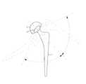
Translated fromKorean도 1은 인체의 고관절 구조를 나타낸 사시도.1 is a perspective view showing the structure of the hip joint of the human body.
도 2는 일반적인 인공 고관절을 나타낸 분리사시도.Figure 2 is an exploded perspective view showing a typical artificial hip joint.
도 3a 내지 도 3c는 인공 고관절의 운동을 나타낸 사시도.3a to 3c are perspective views showing the motion of the artificial hip joint.
도 4는 도 3a의 굴곡 및 신전 상태를 나타낸 측면도.Figure 4 is a side view showing the flexion and extension state of Figure 3a.
도 5는 종래의 인공 고관절용 대퇴스템의 경부 단면 구조의 일 례를 나타낸 단면도.5 is a cross-sectional view showing an example of a neck cross-sectional structure of a conventional artificial hip joint femoral stem.
도 6은 도 5에 의한 대퇴스템의 굴곡 및 신전 상태를 나타낸 측면도.Figure 6 is a side view showing the flexion and extension state of the femoral stem according to FIG.
도 7은 굴곡시 실제 대퇴스템이 삽입물에 간섭되는 상태를 나타낸 단면도.Figure 7 is a cross-sectional view showing a state in which the actual femoral stem interfere with the insert during bending.
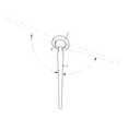
도 8은 본 발명에 의한 대퇴스템의 구조를 나타낸 정면도.8 is a front view showing the structure of the femoral stem according to the present invention.
도 9는 본 발명에 의한 대퇴스템의 경부 단면 구조를 나타낸 단면도.Figure 9 is a cross-sectional view showing the neck cross-sectional structure of the femoral stem according to the present invention.
도 10은 본 발명의 굴곡 상태를 나타낸 단면도.10 is a cross-sectional view showing a curved state of the present invention.
*도면의 주요부분에 대한 부호의 설명* Explanation of symbols for main parts of the drawings
1:대퇴스템1: thigh stem
11:대퇴스템 몸체 11: femoral stem body
12,12a,12b:경부 12,12a, 12b: Cervical
121:원형봉 122:외경 121: Round rod 122: Outer diameter
123,123a:절삭면 124:라운딩부 123,123a: cutting surface 124: rounding part
125:내경 125: inner diameter
13:절두 원추부 14:절단면 13: Frustrated cone 14: Cross section
2:삽입물 3:인공골두2: Insert 3: Artificial Head
4:비구컵4: acetabular cup
본 발명은 인공 고관절용 대퇴스템에 관한 것으로, 보다 상세하게는 관절운동시 실제로 삽입물에 간섭 및 접촉되는 부위를 대퇴스템에서 제거하여 단면적은 최대로 유지하면서 운동범위를 극대화시킬 수 있도록 한 인공 고관절용 대퇴스템 및 상기 대퇴스템의 경부 가공방법에 관한 것이다.The present invention relates to a femoral stem for artificial hips, and more specifically, for artificial hip joints to maximize the range of motion while maintaining the maximum cross-sectional area by removing the portion of the interfering and contacting the insert during the joint movement. It relates to a femoral stem and a neck processing method of the femoral stem.
일반적으로 고관절은 도 1에 도시된 바와 같이 인체의 대퇴골(200)과 골반(100)의 사이를 연결하는 관절로서, 사람이 앉거나 서는데 있어서 가장 중요한 작용을 하는 관절이고, 여러가지의 병적원인과 외상 등에 의해서 손상될 수 있으며, 이를 치유하기 위하여 외과 수술을 통하여 인공 고관절이 적용될 수 있다.In general, the hip joint is a joint connecting the
상기 인공 고관절은 도 2에 도시된 바와 같이 통상 골반의 비구(300)에 고정되는 비구컵(4)과 대퇴골에 삽입 고정되는 대퇴골두(3) 및 대퇴스템(1)으로 구성된다.As shown in FIG. 2, the artificial hip joint is composed of an
상기 비구컵(4)은 세라믹 또는 고분자 폴리에틸렌의 재질로 형성된 반구형의 삽입물(2)이 내부에 고정되고, 상기 대퇴스템(1)은 세라믹 또는 금속재질의 구체로 형성된 인공골두(3)가 단부측에 구비되어 서로 결합되며, 대퇴골 및 대퇴스템(1)의 움직임에 따라 인공골두(3)가 삽입물(2)에 대한 회전운동을 할 수 있도록 되어 있다.The
한편, 상기한 바와 같은 인공 고관절에 있어서 가장 관건이 되는 것은, 어떻게 하면 인체의 고관절에 가장 근접한 관절 운동범위를 갖는 회전운동을 행할 수 있도록 하는데 있다.On the other hand, the most important thing in the artificial hip joint as described above is to be able to perform a rotary motion having a range of motion of the joint closest to the hip joint of the human body.
이러한 관절운동은 도 3a에 도시된 바와 같이 크게 골반에 대해서 대퇴골이 전방향으로 움직이는 굴곡(flexion) 및 그 반대방향으로 움직이는 신전(extension)과, 도 3b에 도시된 바와 같이 골반에 대해서 대퇴골을 안쪽으로 움직이는 내전(adduction) 및 그 반대방향으로 움직이는 외전(abduction)과, 도 3c에 도시된 바와 같이 골반에 대해서 대퇴골을 안쪽으로 회전시키는 내회전(internal rotaion) 및 그 반대방향으로 회전시키는 외회전(external rotation) 등으로 나뉘어진다.This joint motion is largely flexed in the forward movement of the femur with respect to the pelvis and extension in the opposite direction, as shown in FIG. 3A, and in the femur with respect to the pelvis as shown in FIG. 3B. Abduction, which rotates in the opposite direction, and internal rotation that rotates the femur inward with respect to the pelvis, and external rotation that rotates in the opposite direction, as shown in FIG. 3C. ) And so on.
즉, 굴곡 및 신전은 도 4에 도시된 바와 같이 대퇴스템(1)이 삽입물(2)에 대하여 전.후 방향으로 운동하는 것이고, 내전 및 외전은 대퇴스템(1)이 삽입물(2)에 대하여 내.외측으로 운동하는 것이며, 내회전 및 외회전은 대퇴스템(1)이 삽입물(2)에 대하여 내.외측으로 회전운동하는 것이다.That is, the flexion and extension are the
따라서, 인공 고관절의 회전범위는 대퇴스템(1)의 회전 운동범위, 즉 회전각에 의해서 결정되므로 상기 대퇴스템(1)을 제작할 때, 삽입물(2)에 대한 대퇴스템(1)의 간섭을 최소화하기 위해 대퇴스템(1)의 목부분 직경을 줄이게 된다.Therefore, since the range of rotation of the artificial hip joint is determined by the range of rotational motion of the
상기 대퇴스템(1)은 도 2에 도시된 바와 같이 대퇴골에 직접 삽입 고정되는 대퇴스템 몸체(11)와, 인공골두(3)가 끼워져 조립될 수 있게 상기 대퇴스템 몸체(11)의 단부측에 형성되는 절두 원추부(13)와, 상기 절두 원추부(13)와 대퇴스템 몸체(11)의 사이에 형성되는 경부(12), 즉 목부분으로 나뉘어 형성된다.The
여기서, 대퇴스템(1)의 관절운동에 의해서 삽입물(2)에 접촉되는 부분은 대퇴스템의 목 부분, 즉 경부(12)가 되므로 상기 경부(12)의 직경이 작을수록 대퇴스템의 운동범위는 커지게 되나, 그 직경이 너무 작게 되면 부러지게 되므로 한계를 갖게 된다.Here, the part contacting the insert (2) by the joint movement of the femoral stem (1) becomes the neck of the femoral stem, that is, the
이에 따라, 근래에는 이러한 한계를 극복하기 위하여 상기 경부(12)의 한계 직경은 유지하면서 대퇴스템(1)의 관절운동, 특히 굴곡에 대한 운동범위를 크게 할 수 있는 것이 제안된 바 있으며, 이는 도 5에 도시된 바와 같은 종래의 대퇴스템의 경부 단면구조의 일 례가 제안된 바 있다.Accordingly, recently, in order to overcome such limitations, it has been proposed to increase the range of motion of the
상기한 바와 같이 인공 고관절용 대퇴스템은 대퇴스템 몸체(11)와 절두원추부(13) 및 경부(12a)로 구성되고, 상기 경부(12a)는 한계 직경을 갖고 원형으로 형성되는 경부(12)의 단면적에 있어, 도 5에 도시된 바와 같이 대퇴스템의 관절운동시 삽입물(2)과 직접적으로 접촉되는 경부(12a)의 양측면에 절단면(14)을 대칭 형성한 것이다.As described above, the artificial femoral stem is composed of a
즉, 경부(12a)의 한계 직경은 그대로 유지하면서 삽입물에 접촉되는 부분만 면처리하여 경부(12a)의 살을 깍아 내게 됨으로써 그 깍아 낸 살에 대한 보상으로 삽입물에 대한 대퇴스템의 운동범위 확대가 이루어진다는 이론으로 도 6에 도시된 바와 같이 굴곡운동시 대략 10도 가량의 운동범위를 크게 할 수 있다고 했다.In other words, while the limit diameter of the
그러나, 실제로 인공관절 삽입시 상기 비구컵을 40도 내지 50도의 각도로 삽입하기 때문에 관절운동시 경부의 전후면 절단면에 간섭되지 않고, 도 7에 도시된 바와 같이 내측으로 40도 내지 50도의 각도로 틀어진 모서리 부분이 간섭됨으로써 실제로 대략 5도 내외 밖에 인공 고관절의 운동범위가 증가되지 않았던 것이다.However, since the acetabular cup is inserted at an angle of 40 degrees to 50 degrees when the artificial joint is inserted, it does not interfere with the front and rear cut surfaces of the neck during joint movement, and as shown in FIG. 7, the inner cup is twisted at an angle of 40 degrees to 50 degrees. Interference of the corners did not actually increase the range of motion of the hip joint around 5 degrees.
이같이 상기 인공 고관절은, 굴곡이 약 130도 내지 135도 정도로 나타나는 인체 고관절 운동각도에 비하여, 기계상 실제 운동각도가 110도 이상 나타나기 어렵기 때문에 이러한 불일치로 인하여 인공 고관절의 관절 굴곡시 간섭 현상이 발생하게 되는 문제점이 있었던 것이다.As described above, the artificial hip joint has an interference phenomenon when bending the artificial hip joint due to such inconsistency because the actual motion angle of the mechanical joint is less than 110 degrees compared to that of the human hip joint movement in which the flexion is about 130 degrees to 135 degrees. There was a problem.
그리고, 이 간섭현상은 비구컵의 내측 폴리에틸렌 삽입물의 마모 또는 세라믹 삽입물의 파손, 인공 관절의 탈구, 더나아가 인공 관절의 해리 현상을 일으키는 절대적인 요소로 작용하므로 인공 고관절의 관절 운동범위를 증가시키는 것은 필수적이며, 특히 좌식 생활이 필요한 동양권에서는 더 중요한 의미를 갖는다.In addition, it is essential to increase the range of motion of the hip joint because this interference acts as an absolute factor causing wear of the inner polyethylene insert of the acetabular cup or breakage of the ceramic insert, dislocation of the artificial joint, and furthermore, dissociation of the artificial joint. This is especially important in Asian countries where sedentary life is necessary.
이에 본 발명은 상기한 바와 같은 종래의 제반 문제점을 해소하기 위해 창안된 것으로서, 그 목적은 관절운동시 실제로 삽입물에 간섭 및 접촉되는 부위를 대퇴스템에서 제거하여 단면적은 최대로 유지하면서 운동범위를 극대화시킬 수 있도록 하는데 있다.Therefore, the present invention was devised to solve the conventional problems as described above, the object of which is to maximize the range of motion while maintaining the maximum cross-sectional area by removing the portion that actually interferes and contacts the insert during joint movement To make it possible.
이러한 본 발명의 목적을 달성하기 위하여 외경의 전후에서 내측을 향하여 경사지게 절삭하고, 그 대칭되는 절삭면은 상기 외경과 동일 중심을 이루는 가상의 내경에 접하도록 절삭되며, 이 절삭면의 사이를 상기 내경을 따라 라운딩 처리하여 외경의 내측이 외측보다 짧게 형성되도록 가공한 것을 특징으로 한 인공 고관절용 대퇴스템의 경부 가공방법이 제공된다.In order to achieve the object of the present invention to cut inclined toward the inside of the front and rear of the outer diameter, the symmetrical cutting surface is cut in contact with the virtual inner diameter forming the same center as the outer diameter, between the cutting surface between the inner diameter According to the rounding process is provided a neck processing method of the artificial hip joint femoral stem, characterized in that the processing so that the inner side is formed shorter than the outer diameter.
또한, 상기 절삭면의 경사각은 40도 내지 50도 임을 특징으로 한다.In addition, the inclination angle of the cutting surface is characterized in that 40 to 50 degrees.
또한, 상기 외경은 13mm 내지 14mm이고, 내경은 9mm 내지 10mm이며, 절삭면은 1mm 내지 2mm의 깊이로 절삭하여서 된 것을 특징으로 한다.In addition, the outer diameter is 13mm to 14mm, the inner diameter is 9mm to 10mm, the cutting surface is characterized in that the cut to a depth of 1mm to 2mm.
또한, 상기의 방법에 의해서 경부가 가공된 것을 특징으로 한 인공 고관절용 대퇴스템.In addition, the femoral stem for artificial hips, characterized in that the neck portion is processed by the above method.
또한, 대퇴스템 몸체와 절두원추부 및 경부로 구성되는 인공 고관절용 대퇴스템에 있어서, 상기 경부에 해당되는 원형봉의 전후에서 내측으로 경사지고 서로 대칭되는 절삭면이 형성되고, 상기 절삭면의 사이에 상기 원형봉과 동일 중심을 이루는 작은 직경의 원의 반경을 따라 라운딩부가 형성되어 경부의 단면 구조를 이루도록 한 것을 특징으로 한 인공 고관절용 대퇴스템이 제공된다.In addition, in the femoral stem for an artificial hip joint composed of the femoral stem body, the truncated cone portion and the neck, a cutting surface inclined inward and symmetrical with each other in front and rear of the circular rod corresponding to the neck portion is formed between the cutting surfaces. A rounding part is formed along a radius of a circle of a small diameter forming the same center as the circular bar, so that a femoral stem for an artificial hip joint is provided to form a cross-sectional structure of the neck.
또한, 상기 절삭면은 40 내지 50도의 경사각을 이루도록 형성한 것을 특징으로 한다.In addition, the cutting surface is characterized in that formed to form an inclination angle of 40 to 50 degrees.
이하, 첨부된 도면을 참조로 하여 본 발명에 의한 인공 고관절용 대퇴스템의 경부 가공방법에 대하여 상세히 설명한다.Hereinafter, with reference to the accompanying drawings will be described in detail the neck processing method of the artificial hip joint femoral stem according to the present invention.
도 8은 본 발명에 의하여 가공된 대퇴스템을 나타낸 것으로서, 이 인공 고관 절용 대퇴스템은 통상에서와 같이 대퇴골에 직접 삽입 고정되는 대퇴스템 몸체(11)와, 상기 대퇴스템 몸체(11)의 단부측에 형성되어 인공골두(3)가 끼워져 조립되는 절두 원추부(미도시됨)와, 상기 절두 원추부(13)와 대퇴스템 몸체(11)의 사이에 형성되는 경부(12b)로 구성되고, 상기 인공골두(3)는 삽입물(2)에 미끄럼 접촉하면서 회전운동을 하게 된다.Figure 8 shows the femoral stem processed according to the present invention, the artificial femoral femoral stem is a
이러한 인공 고관절용 대퇴스템에 있어, 본 발명은 관절운동시 실제로 삽입물에 간섭 및 접촉되는 부위를 대퇴스템에서 제거하여 관절운동의 범위를 극대화시킬 수 있도록 하면서 단면적은 최대로 유지할 수 있도록 한 것을 특징으로 한 것으로서, 이를 좀더 구체적으로 설명하면 후술한 바와 같다.In the artificial hip joint femoral stem, the present invention is to remove the portion that actually interferes with the insert during the joint movement in the femoral stem to maximize the range of joint movement while maintaining the maximum cross-sectional area As one, it will be described later in more detail.
도 9는 본 발명에 의한 대퇴스템의 경부 단면 구조를 나타낸 단면도이다.9 is a cross-sectional view showing the neck cross-sectional structure of the femoral stem according to the present invention.
이에 도시된 바와 같이 본 발명에 의한 경부(12b)는 원형봉(121)의 전.후에 절삭면(123)(123a)이 서로 대칭을 이루며 내측으로 경사지게 형성되고, 상기 절삭면(123)(123a)의 사이에 라운딩부(124)가 형성된 단면 구조를 갖는 것으로서, 이러한 단면 구조를 형성하기 위한 가공방법은 다음과 같다.As shown therein, the
우선, 원형봉(121)에 해당되는 동일 직경의 외경(122)의 전후에서 내측을 향하여 경사지게 절삭하여 절삭면(123)(123a)을 형성하는데, 이때 상기 절삭면(123)(123a)은 상기 외경(122)과 동일 중심을 이루는 작은 직경의 내경(125)에 접하게 절삭하게 되는 것이며, 상기 내경(125)의 직경 변화에 따른 절삭면(123)(123a)의 이동에 의해서 그 절삭깊이가 변경된다.First, the cutting surfaces 123 and 123a are formed by cutting inclined inward from the front and rear of the
상기 절삭면(123)(123a)의 경사각은 40도 내지 50도를 이루게 되는 것으로서, 상기 경사각은 인공 고관절의 삽입시 대략 45도의 경사각을 이루는 삽입물(2)에 대하여 실제로 경부(12b)가 관절 운동시 상기 삽입물(2)에 간섭 및 접촉되는 부위에 대한 보상각도이고, 40도 내지 50도의 범위는 대퇴스템의 설계시 경부에 대한 강도 변경이 가능한 범위이다.The inclination angle of the cutting surfaces 123 and 123a is 40 degrees to 50 degrees, and the inclination angle is actually the
그리고, 상기 라운딩부(124)는 외경(122)의 내측에 위치하는 절삭면(123)(123a) 사이의 내경(125)의 반경을 따라 절삭함으로써 형성되는 것이며, 이로인하여 정면도 상에서 외경(122)의 내측이 외측보다 짧게 형성되어 서로 비대칭을 이루게 되는 것이다.In addition, the rounding
이와같이 가공되는 본 발명의 바람직한 실시예로서, 본 발명의 외경(122)은 13mm 내지 14mm로 하고, 내경(125)은 9mm 내지 10mm하며, 절삭면(123)(123a)은 1mm 내지 2mm의 깊이로 절삭된다.As a preferred embodiment of the present invention processed as described above, the
이와같이 가공할 때, 본 발명의 단면적은 약 99mm2로서, 대략 원형을 이루는 직경 11mm의 단면적 95.0mm2보다 크고, 굴곡시 회전각 또한 28mm 인공골두를 일 례로 하였을 때, 구형은 112°, 본 발명에 의한 신형은 125°로써 13°의 운동범위의 확대를 가져왔다.When processing in this way, the cross-sectional area of the present invention is about 99mm2 , which is larger than the cross-sectional area of 95.0mm2 with a diameter of about 11mm, which is approximately circular, and the rotation angle during bending is also an example of a 28mm artificial head, the sphere is 112 °, the present invention The new model with 125 ° extended the range of motion to 13 °.
이는 통상 대퇴스템에서 경부가 가질 수 있는 한계 직경은 대개 10mm 정도이나, 최소 9mm의 직경으로도 11mm 직경의 경부보다 큰 단면적을 가지면서 굴곡시 운동범위를 13°증대시킨 결과로 나타난 것으로서, 이를 하기표를 참조로하여 보다 상세히 설명하면 다음과 같다.This is a result of increasing the range of motion by 13 ° with bending, with a cross-sectional area larger than the 11mm diameter neck, which is usually about 10mm in diameter at the femoral stem. Referring to the table in more detail as follows.
상기 표1에 의하면, 통상 13mm의 직경을 갖는 대략 원형의 경부 단면적은 132.7mm2이고, 11mm의 직경을 갖는 경부의 단면적은 95.0mm2이며, 10mm의 직경을 갖는 경부의 단면적은 78.5mm2이고, 9mm의 직경을 갖는 경부의 단면적은 63.6mm2로서 상기 9mm 직경의 경부는 강도면에서 떨어져 실제 적용하지 않는다.According to the above Table 1, the diameter of the substantially circular cross-section having a diameter of typically 13mm is 132.7mm2, the cross-sectional area of the neck has a diameter of 11mm is 95.0mm2, the cross-sectional area of the neck has a diameter of 10mm is 78.5mm2 and The cross-sectional area of the neck having a diameter of 9 mm is 63.6 mm2 , and the neck diameter of 9 mm is separated from the strength and does not actually apply.
따라서, 본 발명은 한계 직경인 10mm보다 작은 9mm의 직경으로 경부를 구성하면서도 11mm의 직경을 갖는 경부의 단면적 95.0mm2보다 큰 대략 99.0mm2의 단면적을 가지므로 단면적은 최대로 유지하면서 후술한 바와 같이 운동범위는 극대화시킬 수 있게 되는 것이다.Accordingly, the present invention has a cross-sectional area of about 99.0 mm2 which is larger than 95.0 mm2 of cross section of the neck having a diameter of 11 mm while constituting the neck with a diameter of 9 mm smaller than the limit diameter of 10 mm. Likewise, the range of motion can be maximized.
상기 표2는 본 발명에 의한 신형 대퇴스템과 구형 대퇴스템의 회전각도를 비교한 표로서, 인공 고관절을 시술할 때, 실제로 삽입하는 각도이다.Table 2 is a table comparing the rotation angles of the new femoral stem and the old femoral stem according to the present invention.
즉, 56mm의 비구컵을 45°하부측 방향으로 경사지게 하면서 다시 15°전방향으로 경사지게 하여 비구에 삽입하는 것과, 대퇴스템을 6°내측방향으로 경사지게 하면서 10°전방향으로 틀어 삽입하는 것을 전제하여 나타난 결과이다.In other words, the 56mm acetabular cup is inclined in the 45 ° lower side and is inclined 15 ° in the forward direction again and inserted into the acetabular, and the femoral stem is inclined in the 6 ° inward direction and twisted in 10 ° forward direction. The result is.
상기 표2에 의하면, 28mm 직경의 인공골두를 갖는 대퇴스템의 경우, 굴곡(flexion) 운동시 구형은 112°인 반면에, 본 발명은 125°로 나타나 13°증가되었고, 32mm 직경의 인공골두를 갖는 대퇴스템의 경우, 구형은 118°인 반면에, 본 발명은 129°로 나타나 11°증가되었음을 알 수 있었으며, 이러한 본 발명의 굴곡 회전각도는 실제 인체 고관절의 굴곡시 나타나는 회전각도인 130도 내지 135도와 거의 차이가 없었다.According to Table 2, in the case of a femoral stem having a 28 mm diameter artificial head, the spherical shape during flexion movement was 112 °, while the present invention was shown to be 125 ° increased 13 °, and a 32 mm diameter artificial head was used. In the case of having a femoral stem, while the spherical shape is 118 °, the present invention was found to be 129 ° and increased by 11 °, and the flexion rotation angle of the present invention is 130 ° to the rotational angle that appears when the actual hip joint is bent. There was little difference in 135 degrees.
상술한 바와 같이 본 발명은 관절운동시 실제로 삽입물에 간섭 및 접촉되는 부위를 대퇴스템에서 제거하여 단면적은 최대로 유지하면서 운동범위를 극대화시킬 수 있도록 함으로써 기존에 인공 고관절의 운동범위가 작아 발생되는 간섭 현상으로 인한 여러 가지 문제점, 예컨대 삽입물의 내측 폴리에틸렌 삽입물의 마모 또는 세라믹 삽입물의 파손, 인공 관절의 탈구, 더나아가 인공 관절의 해리 현상 등을 줄일 수 있는 효과를 갖게 된다.As described above, the present invention removes the site of interference and contact with the insert from the femoral stem during joint movement to maximize the range of motion while maintaining the maximum cross-sectional area, thereby reducing the existing range of motion of the artificial hip joint. Various problems due to the phenomenon, for example, wear of the inner polyethylene insert of the insert or breakage of the ceramic insert, dislocation of the artificial joint, furthermore have the effect of reducing the phenomenon of artificial joint.
Claims (6)
Translated fromKoreanPriority Applications (3)
| Application Number | Priority Date | Filing Date | Title |
|---|---|---|---|
| KR1020040038359AKR100566584B1 (en) | 2004-05-28 | 2004-05-28 | Artificial hip joint femoral stem and neck processing method of the femoral stem |
| US11/119,622US7311735B2 (en) | 2004-05-28 | 2005-05-02 | Femoral stem for artificial coxal articulation and method for processing neck portion thereof |
| CNB2005100710904ACN100413480C (en) | 2004-05-28 | 2005-05-24 | Femoral shaft of artificial hip joint and method of processing neck thereof |
Applications Claiming Priority (1)
| Application Number | Priority Date | Filing Date | Title |
|---|---|---|---|
| KR1020040038359AKR100566584B1 (en) | 2004-05-28 | 2004-05-28 | Artificial hip joint femoral stem and neck processing method of the femoral stem |
Publications (2)
| Publication Number | Publication Date |
|---|---|
| KR20050112919A KR20050112919A (en) | 2005-12-01 |
| KR100566584B1true KR100566584B1 (en) | 2006-03-30 |
Family
ID=35426446
Family Applications (1)
| Application Number | Title | Priority Date | Filing Date |
|---|---|---|---|
| KR1020040038359AExpired - LifetimeKR100566584B1 (en) | 2004-05-28 | 2004-05-28 | Artificial hip joint femoral stem and neck processing method of the femoral stem |
Country Status (3)
| Country | Link |
|---|---|
| US (1) | US7311735B2 (en) |
| KR (1) | KR100566584B1 (en) |
| CN (1) | CN100413480C (en) |
Cited By (1)
| Publication number | Priority date | Publication date | Assignee | Title |
|---|---|---|---|---|
| KR100904088B1 (en) | 2009-01-09 | 2009-06-23 | 주식회사 코렌텍 | Femoral stem for artificial hip |
Families Citing this family (26)
| Publication number | Priority date | Publication date | Assignee | Title |
|---|---|---|---|---|
| US7497874B1 (en) | 2001-02-23 | 2009-03-03 | Biomet Manufacturing Corp. | Knee joint prosthesis |
| US20020120340A1 (en) | 2001-02-23 | 2002-08-29 | Metzger Robert G. | Knee joint prosthesis |
| US7887544B2 (en) | 2003-03-10 | 2011-02-15 | Tornier Sas | Ancillary tool for positioning a glenoid implant |
| FR2863865B1 (en) | 2003-12-19 | 2006-10-06 | Tornier Sa | SHOULDER OR HIP PROSTHESIS AND METHOD OF MOUNTING |
| US8303665B2 (en) | 2004-06-15 | 2012-11-06 | Tornier Sas | Glenoidal component, set of such components and shoulder prosthesis incorporating such a glenoidal component |
| FR2871371B1 (en) | 2004-06-15 | 2007-04-06 | Tornier Sas | GLENOIDAL COMPONENT OF SHOULDER PROSTHESIS, SET OF COMPONENT ELEMENTS OF SUCH COMPONENT AND TOTAL SHOULDER PROSTHESIS INCORPORATING SUCH COMPONENT |
| FR2872025B1 (en) | 2004-06-28 | 2006-08-25 | Tornier Sas | PROSTHESIS OF SHOULDER OR HIP |
| WO2007109319A2 (en) | 2006-03-21 | 2007-09-27 | Axiom Orthopaedics, Inc. | Glenoid component with improved fixation stability |
| EP1996123B1 (en) | 2006-03-21 | 2019-08-28 | Tornier, Inc. | Non-spherical articulating surfaces in shoulder and hip prosthesis |
| WO2007109340A2 (en)* | 2006-03-21 | 2007-09-27 | Axiom Orthopaedics, Inc. | Femoral and humeral stem geometry and implantation method for orthopedic joint reconstruction |
| FR2899790B1 (en) | 2006-04-13 | 2008-06-13 | Tornier Sas | GLENOIDAL COMPONENT FOR TOTAL SHOULDER PROSTHESIS, SET OF SUCH COMPONENTS, AND TOTAL SHOULDER PROSTHESIS COMPRISING SUCH A COMPONENT |
| FR2900045B1 (en) | 2006-04-21 | 2009-01-16 | Tornier Sas | PROSTHESIS OF SHOULDER OR HIP |
| KR100666085B1 (en)* | 2006-05-19 | 2007-01-10 | (주) 코리아나메디칼 | Artificial hip |
| US8163028B2 (en) | 2007-01-10 | 2012-04-24 | Biomet Manufacturing Corp. | Knee joint prosthesis system and method for implantation |
| US8328873B2 (en) | 2007-01-10 | 2012-12-11 | Biomet Manufacturing Corp. | Knee joint prosthesis system and method for implantation |
| US8187280B2 (en) | 2007-10-10 | 2012-05-29 | Biomet Manufacturing Corp. | Knee joint prosthesis system and method for implantation |
| JP5448842B2 (en) | 2007-01-10 | 2014-03-19 | バイオメト マニファクチャリング コーポレイション | Knee joint prosthesis system and implantation method |
| US8562616B2 (en) | 2007-10-10 | 2013-10-22 | Biomet Manufacturing, Llc | Knee joint prosthesis system and method for implantation |
| FR2911773B1 (en) | 2007-01-30 | 2009-03-27 | Tornier Sas | METHOD AND ASSEMBLY OF SURGICAL INSTRUMENTATION FOR POSITIONING A TOTAL REVERSE SHOULDER PROSTHESIS, AND CORRESPONDING PROSTHESIS |
| US20090287309A1 (en) | 2007-01-30 | 2009-11-19 | Tornier Sas | Intra-articular joint replacement |
| US9649194B2 (en) | 2009-07-10 | 2017-05-16 | Peter Forsell | Hip joint device |
| EP3087955B1 (en)* | 2009-07-10 | 2020-12-30 | Implantica Patent Ltd. | Hip joint device |
| US9408652B2 (en) | 2010-04-27 | 2016-08-09 | Tornier Sas | Intra-articular joint replacement and method |
| FR2966343B1 (en) | 2010-10-22 | 2012-12-07 | Tornier Sa | SET OF GLENOIDIAN COMPONENTS OF SHOULDER PROSTHESIS |
| KR101951227B1 (en)* | 2017-03-24 | 2019-04-30 | 주식회사 코렌텍 | Apparatus for Holding Baseplate Trial and Knee Joint Implant Surgical Instrument Set |
| KR102350091B1 (en) | 2019-10-23 | 2022-01-12 | 주식회사 비트러스트메디텍 | Femoral Implant for Animals |
Family Cites Families (6)
| Publication number | Priority date | Publication date | Assignee | Title |
|---|---|---|---|---|
| US5358534A (en)* | 1993-04-29 | 1994-10-25 | Howmedica Inc. | Femoral component for a hip prosthesis |
| CN2167689Y (en)* | 1993-08-23 | 1994-06-08 | 拜奥美特有限公司 | Artificial hipbone component |
| US5776204A (en)* | 1996-05-24 | 1998-07-07 | Howmedica Inc. | Asymmetric hip stem |
| JP2001037792A (en)* | 1999-07-30 | 2001-02-13 | Yasushi Kumazawa | Hip prosthesis |
| CH696418A5 (en)* | 2003-06-20 | 2007-06-15 | Mariasal Invest Nv | hip replacement. |
| US7060102B2 (en)* | 2004-01-21 | 2006-06-13 | Thompson Matthew T | Femoral implant for hip arthroplasty |
- 2004
- 2004-05-28KRKR1020040038359Apatent/KR100566584B1/ennot_activeExpired - Lifetime
- 2005
- 2005-05-02USUS11/119,622patent/US7311735B2/enactiveActive
- 2005-05-24CNCNB2005100710904Apatent/CN100413480C/ennot_activeExpired - Fee Related
Cited By (1)
| Publication number | Priority date | Publication date | Assignee | Title |
|---|---|---|---|---|
| KR100904088B1 (en) | 2009-01-09 | 2009-06-23 | 주식회사 코렌텍 | Femoral stem for artificial hip |
Also Published As
| Publication number | Publication date |
|---|---|
| KR20050112919A (en) | 2005-12-01 |
| US7311735B2 (en) | 2007-12-25 |
| CN1701771A (en) | 2005-11-30 |
| CN100413480C (en) | 2008-08-27 |
| US20050267590A1 (en) | 2005-12-01 |
Similar Documents
| Publication | Publication Date | Title |
|---|---|---|
| KR100566584B1 (en) | Artificial hip joint femoral stem and neck processing method of the femoral stem | |
| EP1413266B1 (en) | Orthopaedic implant having an articulating surface with a conforming area surrounded by a translational area | |
| US4813963A (en) | Femoral component for a hip prosthesis | |
| US6869449B2 (en) | Prosthetic joint component having multiple arcuate bending portions | |
| US5916270A (en) | Hip replacement | |
| US4242759A (en) | M.C.P. Joint replacement | |
| JP4435832B2 (en) | Ball-type triple joint implant system for upper or lower limbs | |
| JP5688281B2 (en) | Artificial knee joint | |
| US20100262254A1 (en) | Metatarsal bone implant | |
| HU219516B (en) | Elbow prothesis | |
| CA2269942A1 (en) | Metacarpal-phalangeal joint replacement | |
| JP2003319956A (en) | Wrist prosthesis | |
| US6413280B1 (en) | Hip joint prosthesis | |
| US4657552A (en) | Prosthesis of the hip | |
| ES3031236T3 (en) | Interphalangeal joint implant | |
| KR100904088B1 (en) | Femoral stem for artificial hip | |
| US9358115B2 (en) | Artificial hip joint stem and artificial hip joint including the same | |
| EP4523663A1 (en) | Apparatus for separating acetabular cup for artificial hip joint | |
| KR100707942B1 (en) | Artificial Hip Ball | |
| EP4400082B1 (en) | Inverse shoulder prosthesis with improved glenosphere | |
| JP4349628B2 (en) | Artificial finger joint | |
| JP4679789B2 (en) | Artificial joint component and method with multiple arcuate bends | |
| JP2003284731A (en) | Hip prosthesis | |
| PL72582Y1 (en) | Endoprosthesis with a sleeve protecting against dislocation | |
| JPH0838525A (en) | Artificial hip joint |
Legal Events
| Date | Code | Title | Description |
|---|---|---|---|
| A201 | Request for examination | ||
| PA0109 | Patent application | Patent event code:PA01091R01D Comment text:Patent Application Patent event date:20040528 | |
| PA0201 | Request for examination | ||
| PG1501 | Laying open of application | ||
| E701 | Decision to grant or registration of patent right | ||
| PE0701 | Decision of registration | Patent event code:PE07011S01D Comment text:Decision to Grant Registration Patent event date:20051226 | |
| GRNT | Written decision to grant | ||
| PR0701 | Registration of establishment | Comment text:Registration of Establishment Patent event date:20060324 Patent event code:PR07011E01D | |
| PR1002 | Payment of registration fee | Payment date:20060327 End annual number:3 Start annual number:1 | |
| PG1601 | Publication of registration | ||
| PR1001 | Payment of annual fee | Payment date:20090114 Start annual number:4 End annual number:4 | |
| PR1001 | Payment of annual fee | Payment date:20100120 Start annual number:5 End annual number:5 | |
| PR1001 | Payment of annual fee | Payment date:20110322 Start annual number:6 End annual number:6 | |
| PR1001 | Payment of annual fee | Payment date:20120320 Start annual number:7 End annual number:7 | |
| FPAY | Annual fee payment | Payment date:20130313 Year of fee payment:8 | |
| PR1001 | Payment of annual fee | Payment date:20130313 Start annual number:8 End annual number:8 | |
| FPAY | Annual fee payment | Payment date:20140305 Year of fee payment:9 | |
| PR1001 | Payment of annual fee | Payment date:20140305 Start annual number:9 End annual number:9 | |
| FPAY | Annual fee payment | Payment date:20150310 Year of fee payment:10 | |
| PR1001 | Payment of annual fee | Payment date:20150310 Start annual number:10 End annual number:10 | |
| FPAY | Annual fee payment | Payment date:20160325 Year of fee payment:11 | |
| PR1001 | Payment of annual fee | Payment date:20160325 Start annual number:11 End annual number:11 | |
| FPAY | Annual fee payment | Payment date:20170324 Year of fee payment:12 | |
| PR1001 | Payment of annual fee | Payment date:20170324 Start annual number:12 End annual number:12 | |
| FPAY | Annual fee payment | Payment date:20180327 Year of fee payment:13 | |
| PR1001 | Payment of annual fee | Payment date:20180327 Start annual number:13 End annual number:13 | |
| FPAY | Annual fee payment | Payment date:20190325 Year of fee payment:14 | |
| PR1001 | Payment of annual fee | Payment date:20190325 Start annual number:14 End annual number:14 | |
| PR1001 | Payment of annual fee | Payment date:20200325 Start annual number:15 End annual number:15 | |
| PR1001 | Payment of annual fee | Payment date:20220210 Start annual number:17 End annual number:17 | |
| PC1801 | Expiration of term | Termination date:20241128 Termination category:Expiration of duration |