KR100566290B1 - Image Scanning Method Using Scan Table and Discrete Cosine Converter - Google Patents
Image Scanning Method Using Scan Table and Discrete Cosine ConverterDownload PDFInfo
- Publication number
- KR100566290B1 KR100566290B1KR1020030064779AKR20030064779AKR100566290B1KR 100566290 B1KR100566290 B1KR 100566290B1KR 1020030064779 AKR1020030064779 AKR 1020030064779AKR 20030064779 AKR20030064779 AKR 20030064779AKR 100566290 B1KR100566290 B1KR 100566290B1
- Authority
- KR
- South Korea
- Prior art keywords
- scan table
- scan
- image
- discrete cosine
- unit
- Prior art date
- Legal status (The legal status is an assumption and is not a legal conclusion. Google has not performed a legal analysis and makes no representation as to the accuracy of the status listed.)
- Expired - Fee Related
Links
Images


Classifications
- H—ELECTRICITY
- H04—ELECTRIC COMMUNICATION TECHNIQUE
- H04N—PICTORIAL COMMUNICATION, e.g. TELEVISION
- H04N19/00—Methods or arrangements for coding, decoding, compressing or decompressing digital video signals
- H04N19/10—Methods or arrangements for coding, decoding, compressing or decompressing digital video signals using adaptive coding
- H04N19/134—Methods or arrangements for coding, decoding, compressing or decompressing digital video signals using adaptive coding characterised by the element, parameter or criterion affecting or controlling the adaptive coding
- H04N19/146—Data rate or code amount at the encoder output
- H04N19/152—Data rate or code amount at the encoder output by measuring the fullness of the transmission buffer
- H—ELECTRICITY
- H04—ELECTRIC COMMUNICATION TECHNIQUE
- H04N—PICTORIAL COMMUNICATION, e.g. TELEVISION
- H04N19/00—Methods or arrangements for coding, decoding, compressing or decompressing digital video signals
- H04N19/10—Methods or arrangements for coding, decoding, compressing or decompressing digital video signals using adaptive coding
- H04N19/102—Methods or arrangements for coding, decoding, compressing or decompressing digital video signals using adaptive coding characterised by the element, parameter or selection affected or controlled by the adaptive coding
- H04N19/129—Scanning of coding units, e.g. zig-zag scan of transform coefficients or flexible macroblock ordering [FMO]
- H—ELECTRICITY
- H04—ELECTRIC COMMUNICATION TECHNIQUE
- H04N—PICTORIAL COMMUNICATION, e.g. TELEVISION
- H04N19/00—Methods or arrangements for coding, decoding, compressing or decompressing digital video signals
- H04N19/60—Methods or arrangements for coding, decoding, compressing or decompressing digital video signals using transform coding
- H04N19/61—Methods or arrangements for coding, decoding, compressing or decompressing digital video signals using transform coding in combination with predictive coding
Landscapes
- Engineering & Computer Science (AREA)
- Multimedia (AREA)
- Signal Processing (AREA)
- Compression Or Coding Systems Of Tv Signals (AREA)
Abstract
Translated fromKoreanDescription
Translated fromKorean도 1 은 2차원 8x8 DCT의 신호 분포 예시도.1 is an exemplary signal distribution diagram of a two-dimensional 8x8 DCT.
도 2(a)~도 2(c) 는 종래의 2차원 8 x 8 DCT 신호의 주사 방식에 대한 예시도.2 (a) to 2 (c) are exemplification diagrams of a conventional scanning method of a two-dimensional 8 × 8 DCT signal.
도 3 은 일반적인 H.263/MPEG 비디오 인코더의 일실시예 구성도.3 is a diagram illustrating an embodiment of a general H.263 / MPEG video encoder.
도 4 는 본 발명에 따른 주사방식을 결정하여 영상을 압축 전송하는 H.263/MPEG 비디오 인코더의 일실시예 구성도.4 is a configuration diagram of an H.263 / MPEG video encoder for compressing and transmitting an image by determining a scanning method according to the present invention.
도 5 는 본 발명에 따른 스캔 테이블의 생성 방법의 일실시예 동작 흐름도.5 is a flowchart illustrating an embodiment of a method of generating a scan table according to the present invention;
도 6 은 도 5의 스캔 테이블의 생성 방법을 8x8 영상에 적용하여 처리하는 상세 동작 흐름도.FIG. 6 is a flowchart illustrating a detailed operation of applying the method of generating the scan table of FIG. 5 to an 8x8 image.
도 7(a)~(f) 는 본 발명에 따른 영상 주사 방법과 종래의 지그재그 방법에 따른 영상 주사 방법의 압축률 비교를 위한 예시도.7 (a) to 7 (f) are exemplary views for comparing compression ratios of an image scanning method according to the present invention and a conventional zigzag method.
본 발명은 영상 정보의 송수신을 위한 것으로 특히, 이산 코사인 변환에 관한 것이다.The present invention relates to the transmission and reception of video information, and more particularly, to discrete cosine transform.
일반적인 영상 전송에 있어서 영상 송신 장치는 영상 데이터를 압축하여 전송하는데, 이와 같이 영상을 압축하기 위하여 공간영역에서 주파수영역으로 변환을 시도한다. 이 과정에서 가장 널리 쓰이는 변환 방법이 이산코사인변환(DCT : Discrete Cosine Transform) 방법이다. 이 변환 방법은 영상 에너지 컴팩션(energy compaction), 빠른 처리속도 등의 장점 때문에 현재 표준 정지영상/동영상 압축에 사용되고 있다.In general video transmission, the image transmission apparatus compresses and transmits image data. In order to compress the image, the image transmission apparatus attempts to convert from the spatial domain to the frequency domain. The most widely used transformation method in this process is the Discrete Cosine Transform (DCT) method. This conversion method is currently used for standard still / movie compression because of its advantages such as image energy compaction and fast processing speed.
이렇게 주파수 영역으로 변환된 영상(정사각형 모양)은 주된 에너지가 좌측 상단에 몰리게 되고, 고주파 성분이 우측 하단으로 몰리게 되는데, 이를 도 1에서 도시하고 있다.In the image (square shape) converted into the frequency domain, the main energy is concentrated at the upper left and the high frequency component is concentrated at the lower right, which is illustrated in FIG. 1.
도 1 은 2차원 8x8 DCT의 신호 분포 예시도이다.1 is an exemplary signal distribution of a two-dimensional 8x8 DCT.
도 1에 도시된 바에 따르면, DCT에 의해서 영상 신호의 주파수 변환은 가로방향 및 세로방향으로 각각 1차원씩 순차적으로 처리하여 2차원의 주파수 신호로 구현된다. 일반적으로 왼쪽 상단 블럭의 계수인 DC(Direct Current)값은 8x8 크기 영상 전체의 평균 에너지를 나타내는 직류성분으로 값이 가장 크다.As shown in FIG. 1, frequency conversion of an image signal by DCT is sequentially performed by one dimension in the horizontal direction and one in the vertical direction, thereby implementing a two-dimensional frequency signal. In general, the direct current (DC) value, which is the coefficient of the upper left block, is the direct current component representing the average energy of the entire 8x8 size image.
그리고, 나머지 63개 블럭의 계수는 AC(Alternative Current)이며, 직류에서 멀어질 수록 고주파 성분을 표현하는 계수이며, 고주파 영역으로 갈 수록 값이 작 아진다.And, the coefficients of the remaining 63 blocks are AC (Alternative Current), which is a coefficient representing a high frequency component as it moves away from a DC, and the value decreases toward a high frequency region.
도 1 에 도시된 예시도의 경우, 64개의 DCT 계수가 각각 어떤 역할을 하는 지 보여주고 있다.In the example diagram shown in FIG. 1, the role of 64 DCT coefficients is shown.
이와 같이 주파수 성분의 계수값으로 표현된 상태에서 양자화를 통하여, 값이 상대적으로 작은 고주파 성분들의 값을 0 또는 0에 가까운 작은 값으로 수렴시키며, 그 값의 검색을 위해 좌측상단부터 우측하단으로 지그재그 모양으로 스캐닝을 한다.Through the quantization in the state expressed as the coefficient value of the frequency component, the values of the high frequency components whose values are relatively small are converged to 0 or a small value close to 0, and zigzag from the upper left to the lower right to retrieve the value. Scan in shape.
이 지그재그 스캐닝을 하게 되면, 이산코사인변환의 특성을 가장 잘 살릴 수 있는 것으로 알려져 있고, 고주파 성분인 0 또는 0에 가까운 작은 값과 저주파 성분인 큰 값을 효율적으로 분리하여 가변길이부호화(VLC, Variable Length Coding)를 하게 된다.This zigzag scanning is known to make the best use of the discrete cosine transform, and it is possible to efficiently separate small values of 0 or 0, which are high frequency components, and large values, which are low frequency components. Length Coding).
이러한 과정은 MPEG(Moving Picture Experts Group)1, 2, 4, H.261, 263, 264, JPEG(Joint Photographic Experts Group) 등의 공통적으로 채택하고 있다.This process is commonly adopted by Moving Picture Experts Group (MPEG) 1, 2, 4, H.261, 263, 264, and Joint Photographic Experts Group (JPEG).
DCT와 양자화를 실행한 상태에서 데이터는 윗쪽 상단 왼쪽에서 오른쪽으로 저장되어 있고, 아래로 내려가는 방향으로 위치하게 된다. 이는 주파수 변환하는 단위를 8 x 8 크기의 정사각형으로 지정하였기 때문이다. 그러나, DCT 변환 후 계수는 블럭 내에서 왼쪽 상단에서부터 우측 하단으로 방사형으로 진행하면서 값이 현저하게 작아지게 된다. 특히 양자화 과정을 거치게 되면, 고주파 성분의 대부분은 0로 수렴하게 된다. 이를 저장된 형태인 윗쪽 상단 왼쪽에서 오른쪽으로, 또한 아래로 내려가는 방향으로 가변길이부호화를 시도하게 될 경우, DCT를 통해 얻어진 압축하기 쉬운 형태가 주는 이점을 제대로 살리지 못하게 된다. 따라서, 고주파 성분과 저주파 성분을 따로 분리할 수 있도록 주사하는 기술이 필요하게 된다.In the DCT and quantization, the data is stored from the upper left to the right, and is positioned in the downward direction. This is because the frequency conversion unit is set to a square of 8 × 8 size. However, after the DCT transform, the coefficients become radially smaller from the upper left to the lower right in the block. In particular, when the quantization process is performed, most of the high frequency components converge to zero. If the variable length encoding is attempted from the upper left to the right and the downward direction, which is a stored form, the advantage of the compressible form obtained through the DCT may be lost. Therefore, there is a need for a technique for scanning so that high frequency components and low frequency components can be separated separately.
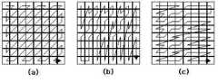
도 2(a)~도 2(c) 는 종래의 2차원 8 x 8 DCT 신호의 주사 방식에 대한 예시도이다.2 (a) to 2 (c) are exemplary diagrams of a conventional scanning method of a two-dimensional 8 × 8 DCT signal.
주사 방식의 목표는 계수의 값이 큰 값부터 작은 값으로 차례로 정렬이 되도록 주사하는 것이다. 그 이유는 계수의 값이 차례로 정렬이 될 때, 가변길이부호화를 통해 압축의 효과가 커지기 때문이다.The goal of the scanning method is to scan so that the values of the coefficients are arranged in order from large to small. The reason for this is that the variable length coding increases the effect of compression when the coefficient values are arranged in order.
도 2(a)는 일반적인 영상의 경우에 사용하는 방법으로 지그재그(zigzag) 스캔 방법이다. 도 2(b)는 수직성분이 강한 경우에 사용하는 방법으로 수직 스캔 방법이다. 도 2(c)는 수평성분이 강한 경우에 사용하는 방법으로 수평 스캔 방법이다.FIG. 2 (a) illustrates a zigzag scanning method used in a general image. Figure 2 (b) is a method used when the vertical component is strong is a vertical scan method. 2 (c) is a horizontal scan method used when the horizontal component is strong.
이상의 도 2(a)~도 2(c)는 현재 MPEG4 표준에서 채택된 주사방식이다. 이 주사방식으로 인하여 DCT 변환의 특성이 극대화 되면서, 가변길이부호화(VLC : Variable Length Cording)가 진행된다.2 (a) to 2 (c) are scan methods adopted by the MPEG-4 standard. This scanning method maximizes the characteristics of the DCT transform and proceeds with variable length coding (VLC).
도 3 은 일반적인 H.263/MPEG 비디오 인코더의 일실시예 구성도이다.3 is a diagram illustrating an embodiment of a general H.263 / MPEG video encoder.
도 3 에 도시된 바와 같이, 일반적인 H.263/MPEG 비디오 인코더는 프레임 단위의 영상 정보를 입력받아 이를 저장하는 원본 저장부(301), 입력된 원본 영상 정보를 엠시디 저장부(311)에 저장된 움직임 보상된 정보와 연산하여 DCT부(303)로 전달하는 제 1 연산부(302), 이산 코사인 변환을 수행하는 DCT부(303), DCT부(303)의 출력을 양자화하는 양자화부(Q)(304), 양자화된 데이터를 역양자화하는 역양자 화부(IQ)(305), 역양자화부(305)의 출력을 역 이산 코사인 변환하는 IDCT부(306), 엠시디 저장부(311)에 저장된 이전 프레임(n-1)의 움직임 보상된 정보와 IDCT부(306)를 통한 디코딩된 당 프레임(n)의 디코딩 정보를 결합하는 결합기(307), 다음 프레임(n)을 위한 디코딩 정보를 저장하는 리콘 저장부(Recon Memory)(308), 리콘 저장부(308)에 저장된 이전 프레임(n-1)의 디코딩 정보와 당 프레임(n)의 원본 영상을 입력받아 움직임 예측을 위한 움직임 벡터와 디퍼렌셜 이미지를 출력하는 움직임 예측부(310), 리콘 저장부(308)에 저장된 이전 프레임(n-1)의 디코딩 정보에 움직임 예측부(310)의 출력을 받아 움직임을 보상하는 움직임 보상부(309), 움직임 보상된 이전 프레임(n-1)을 저장하는 엠시디 저장부(Mced Memory)(311), 양자화된 신호에 대해 주사방식에 따라 주사하여 그 순서를 저장하는 스캔(SCAN)부(312) 및 자주 나오는 값을 작은 비트로 할당하고 가끔 나오는 값일수록 큰 비트로 할당하도록 하는 엔트로피 코딩을 위한 VLC부(109)를 포함한다.As shown in FIG. 3, a general H.263 / MPEG video encoder receives an image information in units of frames and stores the original
도 3 에 도시된 스캔부(312)에 의해 그 주사방식을 결정하고 처리하게 되는데, 도 2 와 같은 주사방식에 의하는 경우 영상블럭마다 그 DCT에 의한 계수값의 분포가 틀려지게 되어 도 2와 같은 일률적인 주사 방식을 취할 경우 최적의 주사 조건을 만족시킬 수 없게 된다.The scanning method is determined and processed by the
따라서, 각각의 영상 블럭마다 그 주사방식을 결정하는 방안에 대한 연구가 이루어져 왔다.Therefore, researches have been made on the method of determining the scanning method for each image block.
그 대표적인 예로 미국 특허 제 5,500,678호의 "Optimized Scanning of Transform Coefficients in Video Coding"(US Pat. 5,500,678), 미국 특허 제 6,263,026 호의 "Signal Compressing System"(US Pat. 6,263,026), 대한민국 특허 출원 제 2002-00709호의 "정지영상 및 동영상 부호화에서 변환 계수의 예측 주사 방법"이 있다.Examples thereof include "Optimized Scanning of Transform Coefficients in Video Coding" of US Pat. No. 5,500,678 (US Pat. 5,500,678), "Signal Compressing System" (US Pat. No. 6,263,026) of US Pat. There is a "predictive scanning method of transform coefficients in still image and moving picture coding".
그 내용을 살펴보면, 미국 특허 제 5,500,678호의 "Optimized Scanning of Transform Coefficients in Video Coding"(US Pat. 5,500,678)는 두 개의 주사방식을 미리 정의해 놓고, 이를 선택적으로 적용하도록 하는 방법으로, 현재 MPEG-4 인트라 코딩 방식의 주사방식으로 채택되어 있으나, 그 목적 영상에 따라 지그재그 주사방식 만을 사용한 것에 비하여 오히려 비트량이 많이 발생할 때도 있다.As for the contents, US Patent No. 5,500, 678, "Optimized Scanning of Transform Coefficients in Video Coding" (US Pat. 5,500, 678) defines two scanning methods in advance and selectively applies them. Although it is adopted as the scanning method of the intra coding method, there are times when a large amount of bits occurs rather than using only the zigzag scanning method depending on the target image.
그리고, 미국 특허 제 6,263,026 호의 "Signal Compressing System"(US Pat. 6,263,026)는 미국 특허 제 5,500,678호가 두 개의 주사 방식을 선택적으로 적용하는 것에 비하여, 보다 많은 다수의 주사 방식을 미리 설정하여 여기에서 가장 알맞은 주사 방식을 선택하고 이를 DCT 계수들에 적용하는 방식이다. 미국 특허 제 5,500,678호의 특허내용의 단점을 보완하기 위하여 보다 많은 주사 방식을 준비해 놓도록 하는 기술이다. 이 방법에서는 주사방식을 준비하고 있기 위해서 별도의 저장공간이 필요하게 되는 단점이 있으며, 미리 준비된 주사방식이 목적영상에 맞지 않으면, 그 부분이 압축률 저하의 요인이 된다.In addition, US Pat. No. 6,263,026, "Signal Compressing System" (US Pat. 6,263,026), compares US Pat. The scanning scheme is selected and applied to the DCT coefficients. In order to make up for the shortcomings of the patent of US Pat. No. 5,500,678, more scanning methods are prepared. In this method, there is a disadvantage in that a separate storage space is required to prepare a scanning method, and if a scanning method prepared in advance does not match the target image, the portion becomes a factor of decompression ratio.
그리고, 대한민국 특허 출원 제 2002-00709호의 "정지영상 및 동영상 부호화에서 변환 계수의 예측 주사 방법"은 미국 특허 제 5,500,678호에 기초하여 동적으로 해당 영상에 대한 주사방식이 미국 특허 제 5,500,678호에서 벗어나는 부분만 변경해 나가도록 하는 기술이다. 또한, 블럭 내에 각 계수들이 "non-zero"가 아닐 확률을 구하여 이 확률 순서대로 주사순서를 정하도록 하는 것이다. 이는 앞서 두 가지 특허기술이 가지는 단점을 보완하지만, DCT 계수의 "zero" 여부만을 체크하여 주사순서를 정하는 방법은 영상이 밝지도, 어둡지도, 색차신호가 짙거나 옅지 않은 이상적인(ideal) 상황에서만 좋은 효율을 보여주게 되는 문제점이 있다.Also, the "predictive scanning method of transform coefficients in still image and video encoding" of Korean Patent Application No. 2002-00709 is based on the US Patent No. 5,500,678 and the scanning method for the corresponding image is dynamically separated from US Patent No. 5,500,678. It's a technique that only changes. In addition, the probability that each coefficient in the block is not "non-zero" is determined to determine the scanning order in this probability order. This compensates for the drawbacks of the two patented technologies, but the method of determining the scanning order by checking only the "zero" of the DCT coefficients is possible only in an ideal situation where the image is not bright, dark, or the color difference signal is dark or light. There is a problem that shows good efficiency.
즉, 이상의 기존 주사방식은 가장 확률적으로 압축효율이 좋을 것같은 방식을 표준으로 정해 놓고, 이를 아무런 연산없이 적용하는 것이다. 이는 영상의 특성이 저주파성분과 고주파 성분이 고르게 나오고, 8 x 8 블럭 내에서 영상 신호가 어느 한쪽으로 치우치거나 특이한 형태(예를 들면 영상의 경계면)를 띠지 않고 평이한 상태를 가정한 것이라 볼 수 있다. 실제 통계적으로 영상을 분석해 보면, 이 표준 지그재그 주사방식을 따르지 않는 DCT 블럭들이 많이 존재함이 확인된다.In other words, the conventional scanning method is to set the standard that is most likely to have a good compression efficiency as a standard, and apply it without any operation. It is assumed that the characteristics of the image are low and high frequency components evenly, and it is assumed that the image signal is flat within 8 x 8 blocks without any bias or unusual shape (for example, the boundary of the image). have. In fact, statistical analysis of the images reveals that there are many DCT blocks that do not follow this standard zigzag scan.
따라서, 영상압축의 효과를 높이기 위해 좀더 정확한 주사방식에 대한 연구가 요구된다.Therefore, more accurate scanning method is required to increase the effect of image compression.
본 발명은, 상기와 같은 문제점을 해결하기 위하여 제안된 것으로, DCT에 있어서 특수한 상황에서도 블럭별로 정확한 주사방식을 결정하는 것이 가능한 스캔 테이블을 이용한 영상 주사방법과 그를 적용한 이산 코사인 변환 장치를 제공하는데 그 목적이 있다.SUMMARY OF THE INVENTION The present invention has been proposed to solve the above problems, and provides an image scanning method using a scan table and a discrete cosine transform apparatus employing the scan table capable of determining an accurate scanning method for each block even in a special situation in DCT. There is a purpose.
또한, 본 발명은 기존의 지그재그 주사방식 및 그에 유사한 기술을 쓰지 않고도 기존의 방식에 비해 연산량의 추가가 크지 않으면서 기존의 지그재그 주사방 식 및 그에 유사한 기술의 단점을 극복하고, 특수한 상황에서 더 나은 압축률을 얻을 수 있는 영상 주사방법을 제공하는데 그 목적이 있다.
In addition, the present invention overcomes the disadvantages of the conventional zigzag scanning method and the similar technology without adding a large amount of calculation compared to the conventional method without using the conventional zigzag scanning method and similar techniques, and in a special situation is better It is an object of the present invention to provide an image scanning method capable of obtaining a compression rate.
상기의 목적을 달성하기 위한 본 발명은, 입력 영상을 이산 코사인 변환(DCT)하고 이를 양자화(Q)하여 주사방식에 따라 주사하여 가변길이 부호화를 통한 압축 비디오 스트림으로 출력하는 이산 코사인 변환 장치에 있어서, 입력된 영상에 대해 소정의 영상 블럭군 단위로 상기 영상 블럭군 내의 각각의 단위 영상 블럭의 동일 위치의 픽셀에 대한 상기 DCT 연산에 따른 계수의 절대값을 누적합한 뒤, 그 누적합의 값에 따른 스캔 테이블을 생성하는 스캔 테이블 생성부; 상기 스캔 테이블 생성부에서 생성된 상기 스캔 테이블에 따라 정렬된 값들을 가변길이 부호화 테이블(VLC table)상의 비트 길이만 누적합하여 비트량을 계산하는 비트율 계산부; 및 상기 이산 코사인 변환된 입력 영상을 입력받아 상기 스캔 테이블 생성부로 입력하여 상기 소정의 블럭군 단위로 스캔 테이블을 생성하도록 제어하고 이에 따른 상기 비트율 계산부의 비트율 값을 입력받아, 상기 스캔 테이블의 용량 증가와 상기 비트율을 이용해 상기 주사방식에 따른 주사를 위한 스캔 테이블을 제공하도록 상기 스캔 테이블 생성부를 제어하는 스캔 제어부를 포함한다.Disclosure of Invention To achieve the above object, the present invention provides a discrete cosine transform apparatus for outputting a compressed video stream through a variable length coding by scanning a scan according to a scanning method by performing a discrete cosine transform (DCT) and quantization (Q) on an input image. And accumulate an absolute value of coefficients according to the DCT operation for pixels at the same position of each unit image block in the image block group with respect to the input image in units of a predetermined image block group, and then, according to the accumulated sum value. A scan table generator for generating a scan table; A bit rate calculation unit for accumulating the bit lengths by accumulating only the bit lengths on the variable length coding table (VLC table) of values arranged according to the scan table generated by the scan table generation unit; And receiving the discrete cosine-converted input image and inputting the input image to the scan table generator to generate a scan table in units of the predetermined block group, and receiving a bit rate value of the bit rate calculator accordingly to increase the capacity of the scan table. And a scan controller configured to control the scan table generator to provide a scan table for scanning according to the scanning method using the bit rate.
또한, 본 발명은, 압축 영상 전송을 위한 영상 주사 방법에 있어서, 상기 압축 영상 전송을 위한 이산 코사인 변환된 영상을 입력받는 제 1 단계; 상기 입력된 이산 코사인 변환된 영상에 대해 소정의 단위의 블럭군을 설정하는 제 2 단계; 상 기 설정된 소정의 블럭군 내의 각각의 단위 블럭에서 동일한 위치의 픽셀에 대한 DCT 처리에 따른 계수의 절대값을 누적합하여 저장하는 제 3 단계; 상기 저장된 단위 블럭 내의 픽셀 위치에 따른 절대값의 누적합의 순서대로 픽셀을 재정렬하고 그에 따른 스캔 테이블을 생성하는 제 4 단계; 및 상기 스캔 테이블에 따라 영상 주사하는 제 5 단계를 포함한다.In addition, the present invention provides a method for scanning a compressed image, comprising: a first step of receiving a discrete cosine transformed image for transmitting the compressed image; Setting a block group of a predetermined unit with respect to the input discrete cosine transformed image; A third step of accumulating and storing an absolute value of coefficients according to DCT processing for pixels at the same position in each unit block in the predetermined block group; A fourth step of rearranging the pixels in order of the cumulative sum of absolute values according to pixel positions in the stored unit block and generating a scan table accordingly; And a fifth step of scanning an image according to the scan table.
이하, 첨부된 도면을 참조하여 본 발명에 따른 바람직한 일실시예를 상세히 설명한다. 도면에서 동일한 구성요소들에 대해서는 비록 다른 도면에 표시되더라도 가능한 한 동일한 참조번호 및 부호로 나타내고 있음에 유의해야 한다. 또한, 본 발명을 설명함에 있어서, 관련된 공지기능 혹은 구성에 대한 구체적인 설명이 본 발명의 요지를 불필요하게 흐릴 수 있다고 판단되는 경우 그 상세한 설명은 생략한다.Hereinafter, exemplary embodiments of the present invention will be described in detail with reference to the accompanying drawings. Note that the same components in the drawings are represented by the same reference numerals and symbols as much as possible even though they are shown in different drawings. In addition, in describing the present invention, when it is determined that a detailed description of a related known function or configuration may unnecessarily obscure the subject matter of the present invention, the detailed description thereof will be omitted.
도 4 는 본 발명에 따른 주사방식을 결정하여 영상을 압축 전송하는 H.263/MPEG 비디오 인코더의 일실시예 구성도이다.4 is a configuration diagram of an H.263 / MPEG video encoder for compressing and transmitting an image by determining a scanning method according to the present invention.
도 4 에 도시된 바와 같이, 본 발명에 따른 H.263/MPEG 비디오 인코더는 도 3 의 일반적인 H.263/MPEG 비디오 인코더와 유사한 구성을 가진다. 그 내용을 상세히 살펴보면, 프레임 단위의 영상 정보를 입력받아 이를 저장하는 원본 저장부(301), 입력된 원본 영상 정보를 엠시디 저장부(311)에 저장된 움직임 보상된 정보와 연산하여 DCT부(303)로 전달하는 제 1 연산부(302), 이산 코사인 변환을 수행하는 DCT부(303), DCT부(303)의 출력을 양자화하는 양자화부(Q)(304), 양자화된 데이터를 역양자화하는 역양자화부(IQ)(305), 역양자화부(305)의 출력을 역 이 산 코사인 변환하는 IDCT부(306), 엠시디 저장부(311)에 저장된 이전 프레임(n-1)의 움직임 보상된 정보와 IDCT부(306)를 통한 디코딩된 당 프레임(n)의 디코딩 정보를 결합하는 결합기(307), 다음 프레임(n)을 위한 디코딩 정보를 저장하는 리콘 저장부(Recon Memory)(308), 리콘 저장부(308)에 저장된 이전 프레임(n-1)의 디코딩 정보와 당 프레임(n)의 원본 영상을 입력받아 움직임 예측을 위한 움직임 벡터와 디퍼렌셜 이미지를 출력하는 움직임 예측부(310), 리콘 저장부(308)에 저장된 이전 프레임(n-1)의 디코딩 정보에 움직임 예측부(310)의 출력을 받아 움직임을 보상하는 움직임 보상부(309), 움직임 보상된 이전 프레임(n-1)을 저장하는 엠시디 저장부(Mced Memory)(311), 양자화된 신호에 대해 주사방식에 따라 주사하여 그 순서를 저장하는 스캔(SCAN)부(312) 및 자주 나오는 값을 작은 비트로 할당하고 가끔 나오는 값일수록 큰 비트로 할당하도록 하는 엔트로피 코딩을 위한 VLC부(109)를 포함하는 일반적인 H.263/MPEG 비디오 인코더의 구성에 본 발명을 적용하기 위한 스캔(Scan) 제어부(401), 스캔 테이블 생성부(402) 및 비트량 계산부(403)을 포함한다.As shown in FIG. 4, the H.263 / MPEG video encoder according to the present invention has a configuration similar to that of the general H.263 / MPEG video encoder of FIG. 3. Looking at the contents in detail, the
본 발명에 따른 H.263/MPEG 비디오 인코더에서 스캔(Scan) 제어부(401), 스캔 테이블 생성부(402) 및 비트량 계산부(403)의 구성 및 그 동작을 좀 더 상세히 살펴보면 다음과 같다.The structure and operation of the
각각의 기능을 먼저 살펴보면, 스캔 테이블 생성부(402)는 입력된 영상 블럭군 내의 각각의 단위 영상 블럭의 동일 위치의 픽셀에 대한 상기 DCT 연산에 따른 계수의 절대값을 누적합 한 뒤, 그 누적합의 값이 큰 순서에 따라 주사 순서를 저 장하는 스캔 테이블을 생성한다.Looking at each function first, the scan
그리고, 비트량 계산부(403)는 지정된 블럭에 할당된 스캔 테이블 생성부(402)에서 생성된 스캔 테이블을 적용하여 정렬된 값들을 가변길이부호화테이블(VLC table) 상의 비트 길이만 누적합하여 비트량을 계산한다.The
그리고, 스캔 제어부(401)는 스캔 테이블에 따른 비트량 계산부(403)의 비트율을 이용하여, 스캔 테이블의 용량 증가와 영상분할에 따른 압축률을 비교하여 최적의 스캔 테이블을 제공하도록 제어한다.In addition, the
DCT(303)부를 통해 이산 코사인 변환된 영상 정보는 양자화(Q)부(304)로 전달됨과 동시에 스캔 제어부(401)로 전달된다. 스캔 제어부(401)는 전달된 이산 코사인 변환된 영상 정보를 스캔 테이블 생성부(402)로 전달하여 스캔 테이블을 생성하도록 제어하고, 해당 스캔 테이블에 따른 비트량을 계산하는 비트량 계산부(403)의 계산 결과에 따라 해당 스캔 테이블을 스캔부(312)의 주사방식으로 사용할 것인지를 결정한다.The discrete cosine transformed image information through the
여기서, 스캔 제어부(401) 및 스캔 테이블 생성부(402)는 영상 정보의 블럭을 소정의 단위로 나누어 그 주사방식을 결정하게 되는데, 비트량 계산부(403)의 계산 결과에 따라 최적화된 영상 정보의 블럭 단위를 결정할 수 있게 된다.Here, the
즉, 스캔 제어부(401) 및 스캔 테이블 생성부(402)는 8x8 영상 프레임의 1개 블럭 단위로 계산을 하고(DCT와 같은 영상변환장치의 크기에 맞게 임의의 크기로 적용하는 것이 가능하다.), 소정의 블럭군에 대하여 8x8 영상 블럭 단위로 블럭내 각각의 좌표에 해당하는 화소들에 대하여 계산을 하여 그 각각의 비트량 계산 결과 에 따라 최적의 스캔 테이블을 스캔부(312)로 전달하여 그 스캔 테이블에 따라 주사하도록 한다. 즉, 본 발명에서는 전송부와 수신부가 정해진 주사 방식을 약속에 의해 선택하는 표준에서와는 달리, 스캔 테이블을 인코딩시에 포함하여 인코딩하고 이를 같이 전송하여 디코딩시에 이를 이용하여 디코딩이 되도록 하는데, 스캔 테이블의 용량이 커지면 압축율이 좋아진다고 하더라도 그 효과가 충분히 반영되지 못한다. 따라서, 스캔 테이블의 용량과 비트율을 이용한 압축율을 트레이드 오프(trade off)하여 최적화된 스캔 테이블을 제공하여야 한다. 이러한 제어 동작을 스캔 제어부(401)를 통해 수행한다. 특히, 각각 블럭군이 생성될 때마다 그 스캔 테이블의 크기는 일정하기때문에 그 크기 값은 스캔 제어부(401)에 저장을 하고 비트율 계산부(403)에서 비트율을 입력받아 그 값을 제어한다.That is, the
예를 들면, 10키로비트(Kbits)의 프레임에 대해 A블럭군의 압축율이 50%이고 그 스캔 테이블의 용량이 1키로비트(Kbits)이면 그 전송 데이터의 용량은 6키로비트가 된다. 반면, 10키로비트(Kbits)의 프레임에 대해 B블럭군의 압축율이 55%이고 그 스캔 테이블의 용량이 0.3키로비트(Kbits)이면 그 전송 데이터의 용량은 5.8키로비트가 된다. 따라서, 비트율로만 따지면 A블럭군의 스캔 테이블이 낫지만, 결과적으로는 B블럭군의 스캔 테이블의 최적의 값이 된다.For example, if the compression rate of the A block group is 50% for a frame of 10 kilobits (Kbits) and the capacity of the scan table is 1 kilobit (Kbits), the capacity of the transmission data is 6 kilobits. On the other hand, if the compression rate of the B-block group is 55% for a frame of 10 kilobits (Kbits) and the capacity of the scan table is 0.3 kilobits (Kbits), the transmission data has a capacity of 5.8 kilobits. Therefore, the scan table of the A block group is preferable in terms of the bit rate, but as a result, the optimum value of the scan table of the B block group is obtained.
도 5 는 본 발명에 따른 스캔 테이블의 생성 방법의 일실시예 동작 흐름도이다. 5 is a flowchart illustrating an embodiment of a method of generating a scan table according to the present invention.
우선, 본 발명에 따른 스캔 테이블의 생성 방법은 우선 주사순서를 정하는 스캔 테이블을 결정하기 위한 블럭군을 설정한다(401). 즉, 어떤 블럭 단위로 스캔 테이블을 결정할 것인지를 정한다.First, in the method of generating a scan table according to the present invention, first, a block group for determining a scan table for determining a scanning order is set (401). That is, it determines which block unit determines the scan table.
그리고, 설정된 블럭군 내의 각각의 단위 블럭에서 동일한 위치의 픽셀에 대한 DCT 처리에 따른 계수의 절대값을 합하여 저장한다(402). 즉, 설정된 블럭군 내에서 동일한 위치의 절대값의 크기에 따른 배열이 가능하게 된다.In
그리고, 저장된 단위 블럭 내의 픽셀 위치에 따른 절대값의 합의 순서대로 픽셀을 재정렬하여 이에 따른 스캔 테이블을 생성한다(403). 즉, 402 과정에서 저장된 절대값의 합을 크기의 순서대로 배열한다.In
그리고, 생성된 스캔 테이블, 즉 재정렬된 픽셀의 순서에 따라 스캔한다(404).The scan is performed according to the generated scan table, that is, the order of the rearranged pixels (404).
이와 같은 도 5의 스캔 테이블의 생성 방법을 8x8 영상에 적용하여 처리하는 상세 동작 흐름도를 도 6 에서 도시하고 있다.FIG. 6 is a flowchart illustrating a detailed operation of applying the method of generating the scan table of FIG. 5 to an 8x8 image.
도 6에 도시된 바에 따르면, 8x8 영상에 적용한 스캔 테이블의 생성 방법은 픽셀의 계수값의 합을 위한 함수 Sum[], 스캔의 순서를 정하기 위한 함수 Scan[], 스캔 테이블 생성을 위한 처리가 수행되었는지를 확인하기 위한 함수 flag[], 영상 블럭을 표시하는 y, 영상 블럭(y)내의 픽셀의 위치를 표시하는 x, 스캔의 순서를 표시하기 위한 인덱스 a, 영상 블럭내의 픽셀의 계수의 합에 따른 순서를 표시하기 위한 인덱스값인 b를 초기화한다(601).As shown in FIG. 6, in the method of generating a scan table applied to an 8x8 image, a function Sum [] for sum of pixel count values, a function Scan [] for sequencing scans, and a process for generating a scan table are performed. A function flag [] to determine whether the image block is shown, y to indicate the image block, x to indicate the position of the pixel in the image block y, an index a to indicate the order of the scan, and a sum of the coefficients of the pixels in the image block. Initializing b, which is an index value for displaying a corresponding sequence, is initialized (601).
그리고, DCT블럭의 인덱스 시작(M)과 종료(N)를 결정한다(602). 즉, 스캔 테이블을 결정하기 위한 블럭군을 설정(401)하는 과정이다.The index start M and the end N of the DCT block are determined (602). That is, a process of setting a block group for determining a scan table (401).
Sum[]을 모두 '0'으로 하고, 영상 블럭을 표시하는 y를 M으로 한다(603). 즉, 영상 블럭 M으로부터 동작을 수행한다.Sum [] is all set to '0', and y representing the video block is set to M (603). That is, the operation is performed from the image block M.
그리고, 영상블럭(y)이 종료값인 N에 이를 때까지 각각의 픽셀의 DCT에 따른 계수의 절대값을 더한다(604, 605, 606, 607, 608, 609). 여기서, 607 과정의 "Sum[x] = Sum[x] + ABS(DCT[y][x])"라는 계산식의 의미는 다음과 같다.The absolute value of the coefficient according to the DCT of each pixel is added until the image block y reaches the end value N (604, 605, 606, 607, 608, 609). Here, the meaning of the calculation formula "Sum [x] = Sum [x] + ABS (DCT [y] [x])" of
설정된 영상 블럭(M~N)군 내의 각각의 단위 영상 블럭은 같은 수의 픽셀들로 구성되며, 그 위치는 모두 동일하다. 따라서, 각각의 단위 영상 블록의 같은 위치에 해당하는 픽셀(x)을 DCT[y][x]라고 표시한다. 즉, DCT[y][x]는 단위 영상 블럭 y의 x번째 픽셀을 의미한다. 따라서, x번째 픽셀의 계수값의 절대값의 합(Sum[x])은 "이전 블럭까지의 x번째 픽셀의 계수값의 절대값의 합(Sum[x]) + 현 블럭의 x번째 픽셀의 계수의 절대값(ABS(DCT[y][x])"로 표시된다.Each unit image block in the set image blocks M to N is composed of the same number of pixels, and the positions thereof are all the same. Therefore, the pixel x corresponding to the same position of each unit image block is denoted as DCT [y] [x]. That is, DCT [y] [x] means the x-th pixel of the unit image block y. Therefore, the sum (Sum [x]) of the absolute value of the count value of the x-th pixel is " Sum [x]) of the count value of the x-th pixel to the previous block + the x-th pixel of the current block. The absolute value of the coefficient (ABS (DCT [y] [x]) ").
이와 같이, 각각의 단위 블럭내의 픽셀의 절대값의 합을 계산하면, flag[]를 초기화한다(610). 그리고, 스캔의 순서를 표시하기 위한 인덱스 a를 "0"으로 초기화한다(611).In this way, when the sum of the absolute values of the pixels in each unit block is calculated, flag [] is initialized (610). The index a for displaying the scanning order is initialized to "0" (611).
그리고, a의 값이 64가 될 때까지(즉, 단위 영상 블럭의 전체 픽셀 : 8x8 영상이므로 픽셀의 수는 64이다.)(612) 최초 인덱스(index)와 최초의 최대값(max)를 "-1"로 설정하고 영상 블럭내의 픽셀의 계수의 합에 따른 순서를 표시하기 위한 인덱스값인 b를 "0"으로 설정한다(613).Then, until the value of a becomes 64 (ie, the total number of pixels of the unit image block: 8x8 image, the number of pixels is 64). (612) The initial index and the initial maximum value "max" are set to ". &Quot; -1 " and b, which is an index value for indicating the order according to the sum of the coefficients of the pixels in the image block, are set to " 0 " (613).
그리고, b가 64가 될 때까지(614) flag[b]가 "1"이면서 Sum[b]가 최대값(max)보다 큰 지를 확인한다(615).Then, it is checked whether flag [b] is "1" and Sum [b] is larger than the maximum value (max) until b becomes 64 (614).
그리고, 확인결과, flag[b]가 "1"이면서 Sum[b]가 최대값(max)보다 크면 최 대값을 Sum[b]로 바꾸고 인덱스를 b로 한다(616).As a result, when flag [b] is "1" and Sum [b] is larger than the maximum value (max), the maximum value is changed to Sum [b] and the index is b (616).
이상의 615, 616의 과정을 b가 64가 될 때까지(614) 반복한다(614, 617).The
이에 따라 최대값을 가지는 픽셀의 위치(b)가 결정된다. 따라서, 최초의 Scan[a]를 인덱스-즉, 절대값 합의 최대값을 갖는 픽셀의 위치-로 결정하고, 해당 픽셀의 위치의 flag[인덱스]값을 "0"으로 함으로써, 해당 픽셀에 대해서는 이미 처리가 되었음을 표시한다(618).Accordingly, the position b of the pixel having the maximum value is determined. Thus, by determining the first Scan [a] as the index-that is, the position of the pixel with the maximum value of the absolute sum-and setting the flag [index] value of the position of the pixel to " 0 " Indicated that the processing has been completed (618).
그리고, 그 순서가 64에 이를때 까지 612 내지 619의 과정을 반복한다.Then, the process of 612 to 619 is repeated until the order reaches 64.
이상의 동작에 따라 블럭군내의 단위 블럭의 픽셀의 위치를 절대값 합의 최대값을 갖는 순서에 따라 차례로 배열한다.According to the above operation, the position of the pixel of the unit block in the block group is arranged in order in order of the maximum value of the absolute sum.
도 7(a)~(f) 는 본 발명에 따른 영상 주사 방법과 종래의 지그재그 방법에 따른 영상 주사 방법의 압축률 비교를 위한 예시도이다.7 (a) to 7 (f) are exemplary views for comparing the compression ratios of the image scanning method according to the present invention and the image scanning method according to the conventional zigzag method.
도 7(a)~(f)에 도시된 바와 같은 각각의 영상에 대한 본 발명에 따른 영상 주사 방법과 종래의 지그재그 방법에 따른 영상 주사 방법의 압축률 비교를 하면 <표 1> 내지 <표 3>과 같다.When comparing the compression ratio of the image scanning method according to the present invention with respect to each image as shown in Figure 7 (a) to (f) and the conventional image scanning method according to the conventional zigzag method <Table 1> to <Table 3> Same as
<표 1>은 각각의 도면에 대한 종래의 지그재그 방법에 따른 영상 주사 방법의 압축률을 표시한 것이다. 각각의 값은 원본(Raw) 데이터 대비 비트량의 비율을 %로 표시한 것이다.Table 1 shows the compression ratios of the image scanning method according to the conventional zigzag method for each figure. Each value represents the ratio of the bit amount to the raw data in%.
<표 2>는 각각의 도면에 대한 본 발명에 따른 영상 주사 방법의 압축률을 표시한 것이다. 각각의 값은 원본(Raw) 데이터 대비 비트량의 비율을 %로 표시한 것이다. <표 2>는 프레임당 1개의 스캔 테이블을 이용하는 경우의 예이다.<Table 2> shows the compression ratio of the image scanning method according to the present invention for each figure. Each value represents the ratio of the bit amount to the raw data in%. Table 2 shows an example of using one scan table per frame.
<표 3>는 각각의 도면에 대한 본 발명에 따른 영상 주사 방법의 압축률을 표시한 것이다. 각각의 값은 원본(Raw) 데이터 대비 비트량의 비율을 %로 표시한 것이다. <표 3>는 프레임당 1024개의 스캔 테이블을 이용하는 경우의 예이다.<Table 3> shows the compression ratio of the image scanning method according to the present invention for each figure. Each value represents the ratio of the bit amount to the raw data in%. Table 3 shows an example of using 1024 scan tables per frame.
상술한 바와 같은 본 발명의 방법은 프로그램으로 구현되어 컴퓨터로 읽을 수 있는 형태로 기록매체(씨디롬, 램, 플로피 디스크, 하드 디스크, 광자기 디스크 등)에 저장될 수 있다.As described above, the method of the present invention may be implemented as a program and stored in a recording medium (CD-ROM, RAM, floppy disk, hard disk, magneto-optical disk, etc.) in a computer-readable form.
이상에서 설명한 본 발명은, 본 발명이 속하는 기술분야에서 통상의 지식을 가진 자에 있어 본 발명의 기술적 사상을 벗어나지 않는 범위내에서 여러 가지 치 환, 변형 및 변경이 가능하므로 전술한 실시예 및 첨부된 도면에 의해 한정되는 것이 아니다.The present invention described above is capable of various substitutions, modifications, and changes without departing from the technical spirit of the present invention for those skilled in the art to which the present invention pertains. It is not limited by the drawings.
상기와 같은 본 발명은, DCT에 있어서 특수한 상황에서도 블럭별로 정확한 주사방식을 결정하는 것이 가능하도록 하는 효과가 있다.The present invention as described above has the effect that it is possible to determine the correct scanning method for each block even in a special situation in the DCT.
또한, 본 발명은 기존의 지그재그 주사방식 및 그에 유사한 기술을 쓰지 않고도 기존의 방식에 비해 더 나은 압축률을 얻을 수 있는 효과가 있다.In addition, the present invention has an effect that can obtain a better compression ratio than the conventional method without using the conventional zigzag scanning method and similar techniques.
Claims (6)
Translated fromKoreanPriority Applications (2)
| Application Number | Priority Date | Filing Date | Title |
|---|---|---|---|
| KR1020030064779AKR100566290B1 (en) | 2003-09-18 | 2003-09-18 | Image Scanning Method Using Scan Table and Discrete Cosine Converter |
| US10/928,395US20050063462A1 (en) | 2003-09-18 | 2004-08-27 | Visual scan method using scan table and discrete cosine transform device employing the same method |
Applications Claiming Priority (1)
| Application Number | Priority Date | Filing Date | Title |
|---|---|---|---|
| KR1020030064779AKR100566290B1 (en) | 2003-09-18 | 2003-09-18 | Image Scanning Method Using Scan Table and Discrete Cosine Converter |
Publications (2)
| Publication Number | Publication Date |
|---|---|
| KR20050028499A KR20050028499A (en) | 2005-03-23 |
| KR100566290B1true KR100566290B1 (en) | 2006-03-30 |
Family
ID=34309437
Family Applications (1)
| Application Number | Title | Priority Date | Filing Date |
|---|---|---|---|
| KR1020030064779AExpired - Fee RelatedKR100566290B1 (en) | 2003-09-18 | 2003-09-18 | Image Scanning Method Using Scan Table and Discrete Cosine Converter |
Country Status (2)
| Country | Link |
|---|---|
| US (1) | US20050063462A1 (en) |
| KR (1) | KR100566290B1 (en) |
Families Citing this family (7)
| Publication number | Priority date | Publication date | Assignee | Title |
|---|---|---|---|---|
| US20060222247A1 (en)* | 2005-04-01 | 2006-10-05 | Bhaskar Sherigar | Hardware implementation of inverse scan for a plurality of standards |
| DE102006017293A1 (en)* | 2005-12-30 | 2007-07-05 | Osram Opto Semiconductors Gmbh | Method for production of optically pumpable semiconductor device, involves providing connection carrier assembly comprising plurality of connection carriers, which are mechanically and fixedly connected to one another |
| KR100882949B1 (en)* | 2006-08-17 | 2009-02-10 | 한국전자통신연구원 | Coding / Decoding Apparatus and Method Using Adaptive Discrete Cosine Transform Coefficient Scanning According to Pixel Similarity |
| US8437391B2 (en)* | 2009-06-26 | 2013-05-07 | Intel Corporation | Transmitting video between two stations in a wireless network |
| US10992958B2 (en) | 2010-12-29 | 2021-04-27 | Qualcomm Incorporated | Video coding using mapped transforms and scanning modes |
| US20130021512A1 (en)* | 2011-07-20 | 2013-01-24 | Broadcom Corporation | Framing of Images in an Image Capture Device |
| GB2519070A (en)* | 2013-10-01 | 2015-04-15 | Sony Corp | Data encoding and decoding |
Family Cites Families (8)
| Publication number | Priority date | Publication date | Assignee | Title |
|---|---|---|---|---|
| JPH02226886A (en)* | 1989-02-28 | 1990-09-10 | Sony Corp | Data transmitter |
| KR960006762B1 (en)* | 1992-02-29 | 1996-05-23 | 삼성전자주식회사 | Efficient 2D Scan Selection Circuit for Image Coding |
| US5367629A (en)* | 1992-12-18 | 1994-11-22 | Sharevision Technology, Inc. | Digital video compression system utilizing vector adaptive transform |
| US5500678A (en)* | 1994-03-18 | 1996-03-19 | At&T Corp. | Optimized scanning of transform coefficients in video coding |
| KR0178198B1 (en)* | 1995-03-28 | 1999-05-01 | 배순훈 | Apparatus for encoding an image signal |
| US6252905B1 (en)* | 1998-02-05 | 2001-06-26 | International Business Machines Corporation | Real-time evaluation of compressed picture quality within a digital video encoder |
| US6956899B2 (en)* | 1998-03-23 | 2005-10-18 | International Business Machines Corporation | Precise bit control apparatus with look-ahead for MPEG encoding |
| JP2001145113A (en)* | 1999-11-17 | 2001-05-25 | Sony Corp | Device and method for image information conversion |
- 2003
- 2003-09-18KRKR1020030064779Apatent/KR100566290B1/ennot_activeExpired - Fee Related
- 2004
- 2004-08-27USUS10/928,395patent/US20050063462A1/ennot_activeAbandoned
Also Published As
| Publication number | Publication date |
|---|---|
| KR20050028499A (en) | 2005-03-23 |
| US20050063462A1 (en) | 2005-03-24 |
Similar Documents
| Publication | Publication Date | Title |
|---|---|---|
| US9420279B2 (en) | Rate control method for multi-layered video coding, and video encoding apparatus and video signal processing apparatus using the rate control method | |
| KR100527690B1 (en) | Signal encoding method and apparatus and decoding method and apparatus | |
| EP1529401B1 (en) | System and method for rate-distortion optimized data partitioning for video coding using backward adaptation | |
| KR100324608B1 (en) | Device and method for predicting and encoding image, device and method for predicting and decoding image, and recording medium | |
| KR0168458B1 (en) | Distorting deminishing method and apparatus | |
| US5848195A (en) | Selection of huffman tables for signal encoding | |
| US6956899B2 (en) | Precise bit control apparatus with look-ahead for MPEG encoding | |
| US20050036549A1 (en) | Method and apparatus for selection of scanning mode in dual pass encoding | |
| US20100172593A1 (en) | Image encoding apparatus, image encoding method, and image encoding program | |
| JP2003250157A (en) | Optimal scanning method of transform coefficients for encoding / decoding still and moving images | |
| KR100961760B1 (en) | Motion estimation method and apparatus referencing discrete cosine transform coefficients | |
| JP4560694B2 (en) | Encoding apparatus and method thereof | |
| JP2005110083A (en) | Data processing apparatus and method, and coding apparatus | |
| JP2007143176A (en) | Motion vector compression method | |
| KR20010078393A (en) | Scalable coding | |
| KR100566290B1 (en) | Image Scanning Method Using Scan Table and Discrete Cosine Converter | |
| KR101086724B1 (en) | Quantization Parameter Determination Method of H.264 / ACC Coder Using Image Complexity and H.264 / ABC Coder Implementing It | |
| JP2000023195A (en) | Image encoding device and method, image decoding device and method and encoded data providing medium | |
| EP1841235A1 (en) | Video compression by adaptive 2D transformation in spatial and temporal direction | |
| CN100493200C (en) | Encoding method, decoding method, encoding device, and decoding device of moving image | |
| JP2005252609A (en) | Data processor, its method and coder | |
| KR20160145181A (en) | System and method for coding in pattern mode for display stream compression (dsc) | |
| KR100832872B1 (en) | Method and apparatus for improving image coding efficiency using geometric transformation | |
| KR100586103B1 (en) | Video encoding method | |
| KR20010104058A (en) | Adaptive quantizer according to DCT mode in MPEG2 encoder |
Legal Events
| Date | Code | Title | Description |
|---|---|---|---|
| A201 | Request for examination | ||
| PA0109 | Patent application | St.27 status event code:A-0-1-A10-A12-nap-PA0109 | |
| PA0201 | Request for examination | St.27 status event code:A-1-2-D10-D11-exm-PA0201 | |
| R18-X000 | Changes to party contact information recorded | St.27 status event code:A-3-3-R10-R18-oth-X000 | |
| PG1501 | Laying open of application | St.27 status event code:A-1-1-Q10-Q12-nap-PG1501 | |
| PN2301 | Change of applicant | St.27 status event code:A-3-3-R10-R13-asn-PN2301 St.27 status event code:A-3-3-R10-R11-asn-PN2301 | |
| PN2301 | Change of applicant | St.27 status event code:A-3-3-R10-R13-asn-PN2301 St.27 status event code:A-3-3-R10-R11-asn-PN2301 | |
| E902 | Notification of reason for refusal | ||
| PE0902 | Notice of grounds for rejection | St.27 status event code:A-1-2-D10-D21-exm-PE0902 | |
| P11-X000 | Amendment of application requested | St.27 status event code:A-2-2-P10-P11-nap-X000 | |
| P13-X000 | Application amended | St.27 status event code:A-2-2-P10-P13-nap-X000 | |
| E701 | Decision to grant or registration of patent right | ||
| PE0701 | Decision of registration | St.27 status event code:A-1-2-D10-D22-exm-PE0701 | |
| GRNT | Written decision to grant | ||
| PR0701 | Registration of establishment | St.27 status event code:A-2-4-F10-F11-exm-PR0701 | |
| PR1002 | Payment of registration fee | St.27 status event code:A-2-2-U10-U11-oth-PR1002 Fee payment year number:1 | |
| PG1601 | Publication of registration | St.27 status event code:A-4-4-Q10-Q13-nap-PG1601 | |
| PR1001 | Payment of annual fee | St.27 status event code:A-4-4-U10-U11-oth-PR1001 Fee payment year number:4 | |
| PR1001 | Payment of annual fee | St.27 status event code:A-4-4-U10-U11-oth-PR1001 Fee payment year number:5 | |
| PR1001 | Payment of annual fee | St.27 status event code:A-4-4-U10-U11-oth-PR1001 Fee payment year number:6 | |
| PR1001 | Payment of annual fee | St.27 status event code:A-4-4-U10-U11-oth-PR1001 Fee payment year number:7 | |
| R18-X000 | Changes to party contact information recorded | St.27 status event code:A-5-5-R10-R18-oth-X000 | |
| FPAY | Annual fee payment | Payment date:20130227 Year of fee payment:8 | |
| PR1001 | Payment of annual fee | St.27 status event code:A-4-4-U10-U11-oth-PR1001 Fee payment year number:8 | |
| P22-X000 | Classification modified | St.27 status event code:A-4-4-P10-P22-nap-X000 | |
| FPAY | Annual fee payment | Payment date:20140227 Year of fee payment:9 | |
| PR1001 | Payment of annual fee | St.27 status event code:A-4-4-U10-U11-oth-PR1001 Fee payment year number:9 | |
| LAPS | Lapse due to unpaid annual fee | ||
| PC1903 | Unpaid annual fee | St.27 status event code:A-4-4-U10-U13-oth-PC1903 Not in force date:20150324 Payment event data comment text:Termination Category : DEFAULT_OF_REGISTRATION_FEE | |
| PC1903 | Unpaid annual fee | St.27 status event code:N-4-6-H10-H13-oth-PC1903 Ip right cessation event data comment text:Termination Category : DEFAULT_OF_REGISTRATION_FEE Not in force date:20150324 | |
| P22-X000 | Classification modified | St.27 status event code:A-4-4-P10-P22-nap-X000 |